Embed Size (px)
Citation preview

Topic No. 850-010-035 January 2018
-1-
FLORIDA DEPARTMENT OF TRANSPORTATION
BRIDGE LOAD RATING MANUAL, 2018
Hal W. Adams Bridge, State Road 51 over Suwannee River

Bridge Load Rating Manual Topic No. 850-010-035
Chapter 1 – Introduction January 2018
-2-
Chapter 1: Introduction
PURPOSE
This Manual provides guidance on bridge load rating in Florida. Load rating analysis
approximates safe carrying capacity for bridges, establishes posting restrictions, and
estimates strength for permit routing. Such analysis directly supports the Department’s
Mission, to “… provide a safe transportation system that ensures the mobility of people
and goods, enhances economic prosperity, and preserves the quality of our environment
and communities.”
AUTHORITY
Sections 20.23(3)(a), and 334.048(3), Florida Statutes, (F.S.)
REFERENCE
The Manual of Uniform Minimum Standards for Design, Construction, and Maintenance
for Streets and Highways (commonly known as the "Florida Greenbook") requires load
rating for all bridges in Florida. This Manual establishes “…uniform minimum standards
and criteria for the design, construction, maintenance, and operation of public roads…,”
for bridge load rating, as part of the Departmental powers and duties described by Florida
Statutes 334.044.
SCOPE
The principal users of this Manual will be all persons involved in bridge load rating in
Florida.
DISTRIBUTION
Submit suggestions, and requests for clarification, to the State Load Rating Engineer at
[email protected]. This Manual, and associated materials (archives,
references, Excel Load Rating Summary Form, and examples), are available for
download at: http://www.fdot.gov/maintenance/LoadRating.shtm

Bridge Load Rating Manual Topic No. 850-010-035
Chapter 1 – Introduction January 2018
-3-
PROCEDURE FOR REVISIONS AND UPDATES
Permanent Technical Revisions to this Manual are made annually, or “as-needed.”
Proposed Revisions are discussed at each Department Load Rating Meeting, held
quarterly. Meetings are attended by the District Structures Maintenance Engineers
(DSME’s), their designated staff specializing in load rating, and a representative of the
State Structures Design Office, who constitute the Load Rating Manual Committee. The
Committee builds consensus, and uses the Online Review System to comment on Draft
Revisions.
Adoption of a Revision is accomplished by responding to all comments submitted by the
Committee, and issuing a Memorandum of Adoption endorsed by the State Structures
Maintenance Engineer. The Memorandum outlines revisions, provides rationale, and
issues directives for implementation. All Load Rating Revisions to this Manual will be
published by the Office of Maintenance. The Forms and Procedures Office will update
the effective date of the revised Manual.
DEFINITIONS AND TERMINOLOGY
Design Load—standard live loading for which the structure was designed or appraised.
Design Loads are collections of fictitious trucks and point-and-lane loads, which describe
or “envelope” real trucks. A Design Load is assessed at two Rating Levels, Inventory and
Operating, defined below.
Load Rating—live load carrying capacity of a bridge.
Load Rating Method, Allowable Stress Rating (ASR)—limits capacity to an allowable
stress. Dead loads are unfactored, and live loads are factored with impact. In Florida,
ASR load ratings use the HS20 Design Load. ASR follows AASHTO Standard
Specifications for Highway Bridges, and MBE Part B.
Load Rating Method, Load Factor Rating (LFR)—uses ultimate strength capacity and
factored loading. LFR also incorporates ASR, for some bridge types. In Florida, LFR
load ratings use the HS20 Design Load. LFR follows AASHTO Standard Specifications
for Highway Bridges, and MBE Part B.
Load Rating Method, Load and Resistance Factor Rating (LRFR)—load rating method
similar to LFR, using more complex factors informed by reliability statistics and refined
analysis. LRFR uses the HL93 Design Load. LRFR follows AASHTO LRFD Bridge
Design Specifications, and MBE Part A.
Bridge Load Rating Manual Topic No. 850-010-035
Chapter 1 – Introduction January 2018
-4-
Rating Level—safety level of the live load capacity for a highway bridge.
Rating Level, Inventory—unlimited application of live loads at this level will not damage
the bridge. This is the lowest rating. Permissible stressing is minimized.
Rating Level, Operating—unlimited application of live loads at this level may shorten the
life of the bridge. This is the highest rating. Permissible stressing is maximized.
Rating Level, Legal—in Florida, excepting LRFR Steel Service, the Legal Level is
equivalent to the Operating Level. Florida has 7 Legal Loads, described in the Appendix
to this Manual, which envelope the truck configurations permitted by Florida law.
Rating Level, Routine Permit—in Florida, excepting certain LRFR Service tests, the
Routine Permit Level is equivalent to the Operating Level. Florida uses the FL120
Routine Permit Vehicle as a reference vehicle, to infer ratings for other permit trucks.
National Bridge Inventory (NBI)—data required to fulfill the National Bridge Inspection
Standards. For a description of the NBI data fields, see the FDOT Bridge Management
System Coding Guide, referenced below.
Pontis/BrM—bridge data management software.
Rating—rated capacity in tons, equivalent to (Gross Vehicle Weight)∙(Rating Factor).
Rating Factor (RF)—(Capacity – Dead Load) / (Live Load). Each component of the RF
equation is factored.

Bridge Load Rating Manual Topic No. 850-010-035
Chapter 1 – Introduction January 2018
-5-
REFERENCES
Links for the following references are at:
http://www.fdot.gov/maintenance/LoadRating.shtm
AASHTO LRFD Bridge Design Specifications (LRFD), 8th Ed.
AASHTO Manual for Bridge Evaluation (MBE), 2nd Ed. with 11’ 13’ 14’ 15’ & 16’ Interims.
AASHTO Standard Spec. for Highway Bridges (Std.Spec.), 17th Ed. with 2005 Interims.
FDOT Bridge and Other Structures Inspection and Reporting Manual, 2016.
FDOT Bridge Management System Coding Guide (BMS).
FDOT Construction Project Administration Manual (CPAM).
FDOT Design Manual (FDM), 2018.
FDOT Plans Preparation Manual (PPM), 2017.
FDOT Standard Specifications for Road and Bridge Construction, 2018.
FDOT Structures Manual Volume 1, Structures Design Guidelines (SDG), 2018.
Manual of Uniform Minimum Standards for Design, Construction and Maintenance for
Streets and Highways (GREENBOOK), 2016.

Bridge Load Rating Manual Topic No. 850-010-035
Chapter 2 – Process January 2018
-6-
Chapter 2: Load Rating Process and Procedure
CONCEPTS
Utilizing engineering judgment, identify components that may control the load rating, and
analyze those components for all applicable limit states and vehicles until the governing
member(s) are found. Before confining the analysis to the superstructure, consider the
substructure. For example rotted timber piles, settlement, excessive scour, or distressed
pile caps would all warrant additional consideration.
Accurate load ratings are essential to permit routing. Operating and FL120 results are
used to route permit overloads on State highways in Florida. Overloads include blanket
permits, like cranes, and special trip permits, such as bridge girder deliveries.
Use an appropriate level of analysis to establish a safe load carrying capacity that does
not unduly restrict legal and permit traffic. Begin with a simplified level of analysis. Refine
the analysis as necessary to provide a more accurate load rating. “As necessary” means:
1. Appropriately consider posting avoidance.
2. Apply additional scrutiny to results that markedly differ from the Design Load.
3. Apply refinements to results that obviously mischaracterize the safe carrying
capacity of the bridge.
Adopt one method of analysis, and do not report a mixed-method summary. For example,
if the HL93 Inventory rating uses refined distribution, then the HL93 Operating and FL120
Permit ratings also require refined distribution. Be consistent. The governing
methodology and distribution shall apply to the entire structure. While the contents of an
analysis may explore several methods, clearly and consistently state which method was
ultimately adopted, and which results govern.
Bridge Load Rating Manual Topic No. 850-010-035
Chapter 2 – Process January 2018
-7-
DEFINITION, COMPLETE LOAD RATING
A complete load rating is a high-quality PDF report, wherein any scans are 300dpi+ and
75%+ quality compression. Seal digital deliveries unlocked; this retains the original
document ("view sealed version"), but permits subsequent comments. Contents include:
1. SUMMARY. Load rating summary form (Excel), sealed by a Florida P.E.
2. NARRATIVE. Brief description of inspection findings, methodology, and assumptions.
3. PLANS. Plan sheets required to perform the analysis (not the entire plan set).
4. CALCULATIONS. Inputs, intermediate calculations, and summarized outputs.
5. QUICK CHECK. At a minimum, confirmation of the governing Design Operating
Rating; show the factored components of the rating factor equation. A more
comprehensive check is recommended, especially when results significantly differ
from the original Design Load increased to the Operating Level.
Additionally, submit all inputs in native ready-to-run format. Exceptions include hand
calculations, and proprietary worksheets that are sufficiently transparent.
DEFINITION, AS-BUILT LOAD RATING
Typically, an As-Built Load Rating confirms that the Design Load Rating (As-Bid Load
Rating) remains valid, and a sealed summary form indicating it is reflective of the As-Built
conditions will suffice. However, if the Engineer of Record (EOR) finds that the As-Built
condition substantively differs from Design, then an As-Built load rating constitutes a
complete revision of the Design Load Rating.
DEFINITION, AS-BUILT DOCUMENTS PACKAGE
The As-Built Structure Documents Package contains select bridge records that the
District Structures Maintenance Office (DSMO) is required to store for the life of the bridge
(MBE Section 2). For FDOT projects, follow the CPAM. For other projects, the package
is a ZIP archive containing one bridge; PDF contents are either direct-to-pdf, or scanned
at 300dpi+ and 75%+ quality compression. The package contains:
1. Foundation records: pile driving records, shaft tip elevations, and boring logs.
2. Structure plans: shop drawings, and As-Built plans (alternatively sealed design plans,
with a summary of construction changes).
3. For bridges traversing water, a sealed Hydraulic analysis plan sheet.
4. Sealed As-Built load rating.

Bridge Load Rating Manual Topic No. 850-010-035
Chapter 2 – Process January 2018
-8-
TABLE 2-1—EXISTING BRIDGES
PHASE ACTION
NBI
Inspection
In Pontis/BrM Inspection Notes, state whether the current load rating is
complete and applicable. The note should indicate who made the
determination, and when.
“Complete” means that the rating complies with the rules1 that were in
effect when the rating was performed. Historic ratings shall, at a
minimum, include a summary and calculations. “Applicable” means that
the configuration and condition of the bridge has not substantially
changed, since the calculations were performed.
If the analysis is incomplete or inapplicable, notify the DSME and begin
revisions.
Load Rating
Revision
Within 90 days of the date that the NBI Inspection Report was sealed, or
earlier as the DSME determines for emergencies, (1) Revisions are to be
completed and input into Pontis/BrM, and (2) If the analysis recommends
posting for weight, a notification shall be sent to the bridge Owner. For
load rating revisions, follow FDOT Figure 2-1.
Posting Posting deficiencies shall be addressed within 30 days of receipt of
notification to the bridge Owner; see Chapter 7 of this Manual.
1. From time-to-time, interim revisions are required. For example, all structures with
transverse floorbeams are required to report transverse data.

Bridge Load Rating Manual Topic No. 850-010-035
Chapter 2 – Process January 2018
-9-
TABLE 2-2—WIDENINGS, REHABILITATIONS, AND NEW BRIDGES
PHASE ACTION RESPONSE, LOAD RATING SPECIALIST
90%
Superstructure
Plans
EOR –
Submit1 Draft
Load Rating
Within 30 days, review and return comments to the
designer or analyst.
Final Plans
(Design-Bid-
Build), or
Released for
Construction
(Design-Build)
EOR –
Submit1
sealed Design
Load Rating
Within 14 days:
• Confirm that review comments were
addressed, and respond with a receipt to the
EOR. If the rating is acceptable, archive it to
EDMS. Otherwise request revisions.
• Determine whether the new load rating
applies. At a strengthening project, for
example, the new rating will not apply until
that strengthening has occurred.
• Document the determination in Pontis/BrM
Structures Notes, and accordingly update or
retain the Pontis/BrM load rating data.
Superstructure
Nearing
Completion
CEI – Submit1
the As-Built
Documents
Package
Determine whether the As-Built Documents Package
is complete. If so, confirm the schedule for the final
inspection. Otherwise, specify insufficiencies within
the As-Built Documents Package, schedule a safety
inspection, and establish a timeline for completion.
Superstructure
Complete
LEAD
BRIDGE
INSPECTOR
– Submit1 draft
inspection
When the initial NBI inspection occurs, or before,
apply the As-Built load rating to Pontis/BrM, and
archive the data to EDMS. If a load rating is not
available, the Engineer responsible for the inspection
will use engineering judgment, assign a sealed
temporary load rating, and notify the State Load
Rating Engineer; complete an analysis and input the
results within 90 days of the date that the NBI report
was sealed.
1. Submit deliverables to [email protected], where “X” is the District No.
For example, District 1 is [email protected].
For widenings and rehabilitations, follow FDOT Figure 2-2, and FDOT Structures Design
Guidelines, Chapter 7. For new bridges, provide Strength for the FL120 (RFFL120 ≥ 1.00),
and comply with FDOT Structures Design Guidelines. New (non-widening) precast
culvert projects must provide a load rating, or contract language that requires the
Contractor to provide a load rating in accordance with this Manual.

Bridge Load Rating Manual Topic No. 850-010-035
Chapter 2 – Process January 2018
-10-
FDOT Figure 2-1— Existing Bridges FDOT Fig.2-2—Widening & Rehab.
1. LFR and ASR are not permitted among spans exceeding 200 feet.
2. ASR is not permitted for bridges on the National Highway System.
3. At existing bridges, if RFHL93 Operating < 1.30, or if LFR/ASR, assess the Legal Loads.
4. Widenings and rehabilitations need not assess the Florida Legal Loads; the HL93,
FL120, and HS20 Rating Factor requirements are sufficient.
5. FDOT Additional Methods can be found at SDG 7.1.1 C.
NO
YES
Choose a method, in order of Department preference:
(1) Load & Resistance Factor Rating (LRFR)
(2) Load Factor Rating (LFR)1
(3) Allowable Stress Rating (ASR)1,2
YES
Load rate the Florida Legal Loads.
NO
YES
END: POST THE BRIDGE FOR LOAD
START START
Choose one, and obtain Department approval: (1) Strengthen. (2) Replace. (3) Apply for a Variation. Include calculations. Explain why strengthening is not practicable, why replacement is not warranted.
NO
YES4
YES4
NO NO
YES4
END
LRFR Approximate Distribution:
RFHL93 Inventory ≥ 1.00
& RFFL120 ≥ 1.00?
END
LRFR, FDOT Additional Methods5:
RFHL93 Inventory ≥ 1.00
& RFFL120 ≥ 1.00?
END
LFR1 Approximate Distribution:
RFHS20 Inventory ≥ 1.00
& RFHS20 Operating ≥1.67
?
Posting Avoidance. See Chapter 7.
END HL93 Operating3
RF ≥ 1.30?
END All Legal Load RFs ≥ 1.00?
END All Legal Load RFs ≥ 1.00?

Bridge Load Rating Manual Topic No. 850-010-035
Chapter 2 – Process January 2018
-11-
COMMENTARY, DX-LOADRATING EMAIL
The delivery email [email protected], where “X” is the District Number,
reliably specifies the address of the reviewer and end-user of the documents that this
chapter requires. Submissions may also be accomplished by alternative means
established by contract documents, provided that the delivery mechanism is effective and
efficient. For example, the CPAM process of notifying the DSME is also acceptable.
CITATIONS, EXTERNAL MANUALS
Load rating involves Design, Construction, and Maintenance. Participants include State,
Toll, and Local authorities. To accommodate a variety of participants, and to develop a
coherent and practicable load rating policy and process, this Manual draws from other
manuals.
SDG. Structures Design Guidelines (SDG), from 2018 FDOT Structures Manual
Volume 1, governs all Department structures design, and informs all bridge structures
design in Florida. At 90% plans, perform a load rating (1.7). For bridge-size culverts, see
3.15.14. For bascule bridges, see 8.4. Widen and rehabilitate bridges in accordance with
Chapter 7. This Manual adopts the SDG, and the SDG refers to this Manual for load
rating. However note these differences:
1. In addition to the standard Load Rating Summary Form (Excel), the Design of new
bridges and widenings also requires a Load Rating Plan Sheet. See:
http://www.fdot.gov/structures/CADD/standards/CurrentStandards/LRFRsummaryTables.pdf
2. The design of bascule bridges requires an unpinned span lock assumption, as a part
of the load rating analysis. For the appraisal of existing bascule bridges, this Manual
defers to the local District Structures Maintenance Engineer for specific instructions.
GREENBOOK. Locally-owned bridges conform to the Manual of Uniform Minimum
Standard for Design, Construction and Maintenance for Streets and Highways (commonly
referred to as the Florida “Greenbook”). Design per LRFD (Ch.17 C). Perform a
hydraulic analysis (Ch.17 C.4a). Provide certain As-Built structure documents (Ch.17 D).
For load rating, refer to this Manual (Ch.17 H).

Bridge Load Rating Manual Topic No. 850-010-035
Chapter 2 – Process January 2018
-12-
PPM/FDM. All State-owned bridges, and many others, abide by the FDOT Plans
Preparation Manual (PPM), or the new FDOT Design Manual (FDM). The FDM replaces
the PPM for Design-Bid-Build projects that start in 2018, and Design-Build projects that
start in 2019 (http://www.fdot.gov/design/Bulletins/RDB17-12.pdf). For Design Variations
allowing deficient strength, seek a recommendation from the Office of Maintenance, and
approval from the State Structures Design Engineer, by providing calculations and a
“Detailed explanation of why the criteria or standard cannot be complied with or is not
applicable” (PPM Vol. 1 Ch. 23, or FDM 122.4). For all projects, see the load rating
sections (PPM Vol. 1 at 26.17, or FDM 121.17).
CPAM. The FDOT Construction Project Administration Manual (CPAM) specifies
procedures for the construction of State projects. Non-State projects may also utilize the
CPAM, or concepts within the CPAM. Submit As-Built bridge documents (5.12.8).
Provide As-Built load ratings and inspections notice to the DSME (10.11.3, 10.11.4).
Archive certain As-Built documents to Construction Documents Management System
(CDMS), and attribute those documents with the Structure Number (10.11.5).
Incidentally, the maximum retention time for CDMS documents is 15 years; Structures
Maintenance reviews and archives As-Built documents more durably, for 99 years.

Bridge Load Rating Manual Topic No. 850-010-035
Chapter 3 – Responsibilities January 2018
-13-
Chapter 3: Responsibilities
DISTRICT STRUCTURES MAINTENANCE OFFICE
1. Ensure that every bridge within the jurisdiction of the District is properly load rated,
timely updated, and accurately reported to the Bridge Management Database, in
accordance with this Manual.
2. Perform and review load ratings. Review all new load ratings cursorily, and at least
10% of new load ratings thoroughly, with separate and unique review calculations for
the governing elements.
3. Review NBI inspections, and determine whether the present load rating remains
complete and applicable.
4. Administer and verify bridge load posting with the District Local Bridge Coordinator.
5. Provide information to the Overweight/Over-Dimensional Permit Office to facilitate
safe routing.
6. Assist the Office of Maintenance, other branches of the Department, and local
authorities.
7. Write and maintain a Quality Control (QC) Plan that explains how these tasks are
accomplished. The QC Plan need not reiterate the contents of this Manual; instead,
the QC Plan should emphasize day-to-day tracking and documentation.
DISTRICT MAINTENANCE ENGINEER
Designate staff to inform the Overweight/Over-Dimensional Permit Office of temporary
clearance restrictions due to construction activity. Additionally, advise upon the best time
to move permitted cargo, with respect to special events and local traffic conditions.
OFFICE OF MAINTENANCE
1. Annually perform a Quality Assurance Review (QAR) of the load rating performance
of each District. The current schedule, monitoring plans, critical requirements and
compliance indicators are included in the Quality Assurance Plan available at the
internal Office of Maintenance SharePoint site:
http://cosharepoint.dot.state.fl.us/sites/maintenance/
2. Assist Districts, other branches of the Department, and local authorities.
3. Maintain this Manual.
4. Resolve inconsistencies arising from FDOT guidance.
5. Provide training, share new procedures, and respond to questions.

Bridge Load Rating Manual Topic No. 850-010-035
Chapter 3 – Responsibilities January 2018
-14-
6. Provide load rating examples.
7. Review load posting requests for State-maintained bridges.
8. Provide courtesy reviews, for Districts and local agencies.
9. Perform evaluations and load ratings for State-owned bridges to improve commercial
truck mobility.
STATE STRUCTURES DESIGN OFFICE
1. Review this Manual.
2. Review new and proposed design methods.
3. Assist the Office of Maintenance with load testing and complex analysis.
CONSULTANTS
1. Assist the Department in accordance with contract documents.
2. Perform and review load ratings in accordance with this Manual.
3. Write and maintain a Quality Control (QC) Plan that explains how load rating reviews
are performed and documented. Within the QC Plan, include a Quality Assurance
Review (QAR) component, which investigates and reports upon the quality of the work
product, annually or more frequently. The QC plan will state where the QAR records
are kept.
CHAPTER SEQUENCE
This Manual retains a legacy numbering sequence; chapter numbers 4 and 5 are omitted.

Bridge Load Rating Manual Topic No. 850-010-035
Chapter 4 January 2018
-15-
Chapter 4
This Chapter is reserved for future use. MBE Section 4—Inspection is unmodified.

Bridge Load Rating Manual Topic No. 850-010-035
Chapter 5 January 2018
-16-
Chapter 5
This Chapter is reserved for future use. MBE Section 5—Materials is unmodified.

Bridge Load Rating Manual Topic No. 850-010-035
Chapter 6 – Load Rating Analysis January 2018
-17-
Chapter 6: Load Rating Analysis
Chapter 6 of this Manual modifies the current AASHTO Manual for Bridge Evaluation
(MBE). The MBE governs on all relevant topics not directly addressed in this Manual.
6.1—SCOPE
Remove: “No preference is placed on any rating method. Any of these three methods
identified above may be used to establish live load capacities and load limits for the
purposes of load posting.”
Add: “The load rating of all bridges shall be in accordance with Chapter 2 of this Manual.
The Department prefers LRFR.”
C6.1
Add: For segmental bridges, since ASR and LFR are inadequate, use LRFR. For spans
exceeding 200 feet, since MBE Part B legal loading is excessive, use LRFR.
Regarding ASR, in 1993 the FHWA requested that all ASR ratings on the National
Highway System (NHS) be rerated with LFR. FDOT and FHWA agreed that only
structurally deficient or functionally obsolete NHS ratings required re-rating. These, and
all subsequent revisions to NHS ratings, shall use either LFR or LRFR.
6.1.4—Bridges with Unknown Structural Components
Replace subsection with: For bridges that lack plans, perform field measurements. At a
minimum, the field kit should include a measuring tape, a caliper, and a pachometer. Use
plans from a similar bridge or era-appropriate code to conservatively approximate the
reinforcement, and analyze the bridge. If the reinforcement cannot be estimated, and the
bridge shows no distress, an assigned load rating is acceptable. Otherwise perform
additional non-destructive testing as necessary, and analyze or proof-test the bridge.
6.1.5.2—Substructures
Add: Analyze all straddle bents.

Bridge Load Rating Manual Topic No. 850-010-035
Chapter 6 – Load Rating Analysis January 2018
-18-
Part A: LRFR
6A.1.5—Load and Resistance Factor Rating
Remove: “A detailed rating flow chart is included in Appendix A6A.”
Add: The routine FDOT rating process is described in Chapter 2 of this Manual.
6A.1.5.2—Legal Load Rating
Remove: “Live load factors are selected based on the truck traffic conditions at the site.”
Add: Legal live load factors are consistently applied for all traffic conditions.
6A.1.5.3—Permit Load Rating
Remove: “Calibrated load factors by permit type and traffic conditions at the site are
specified for checking the load effects induced by the passage of the overweight truck.”
Add: FL120 Routine Permit live load factors are consistently applied for all traffic
conditions. Special Permits shall follow the MBE requirements, unless otherwise
specified in writing by the Office of Maintenance.
6A.2—LOADS FOR EVALUATION
6A.2.3.1—Vehicular Live Loads (Gravity Loads): LL
Replace subsection with: Live load models include: (1) HL93 Design Load, (2) Florida
Legal Loads, and (3) FL120 Routine Permit. For Design, Legal, and Routine Permits,
apply consistent live load factors for all traffic conditions, as specified in FDOT Table
6A.4.2.2-1. For Special Permits, use the Actual Permit Truck, and live load factors as
specified by the MBE.
Bridge Load Rating Manual Topic No. 850-010-035
Chapter 6 – Load Rating Analysis January 2018
-19-
6A.3.2—Approximate Methods of Structural Analysis
Add: Extend the range of applicability for approximate distribution as described at SDG
2.9. Also, if concrete parapets or barriers are continuous near midspan (without open
joints), neglect the exterior beam rigid section assumption at LRFD Eq. C4.6.2.2.2d-1.
C6A.3.2
Add: Continuous parapets and barriers stiffen the exterior section. While parapets and
barriers are susceptible to vehicular impacts, the same is true for beams (over-height
vehicular impacts). Load testing has shown that, while the parapet-beam stiffness does
attract load, the stresses are lower than the rigid section assumption surmises. The
modification only applies to continuous parapets; the rigid section assumption may apply
to bridges with parapets containing open joints near midspan.
6A.3.3—Refined Methods of Analysis
Add: Refined methods include two or three dimensional models using grid or finite-
element analysis. Excepting parapet self-weight, and posting avoidance, refined
analyses may not benefit from edge stiffening effects from barriers or other
appurtenances. On the load rating summary form, state the name and the version of the
software that was used. Within the load rating narrative, explain why refined analysis was
used.

Bridge Load Rating Manual Topic No. 850-010-035
Chapter 6 – Load Rating Analysis January 2018
-20-
6A.4—LOAD RATING PROCEDURES
6A.4.1—Introduction
Replace subsection with: Use 6A.4.2—General Load-Rating Equation with FDOT Table
6A.4.2.2-1—LRFR Limit States and Load Factors. Evaluate FL120 Permit, HL93
Inventory, and HL93 Operating. For existing bridges, if the HL93 Operating Rating Factor
is less than 1.30, then additionally evaluate the Florida Legal Loads.
6A.4.2—General Load Rating Equation
6A.4.2.1—General
Add:
RATING = RF∙GVW = Permissible weight in tons
RF = Rating factor
GVW = Gross vehicle weight (axle loading of the heaviest truck that the vehicle considers)
For example, the rating for the HL93 is (36 tons)∙(HL93 Rating Factor), irrespective of
whether the tandem or another combination governs. Likewise, for a long-span bridge,
the rating for an SU4 is (35 tons)∙(SU4 Rating Factor), even if the lane-and-truck
combination governs.
C6A.4.2.1
Add: While permit routing uses rating factors, the Bridge Management System retains
ratings in terms of tons. The RATING = RF∙GVW standard forms a reliable way to
reconstruct rating factors from ratings in tons.

Bridge Load Rating Manual Topic No. 850-010-035
Chapter 6 – Load Rating Analysis January 2018
-21-
6A.4.2.2—Limit States
Replace Table 6A.4.2.2-1 with:
FDOT Table 6A.4.2.2-1—LRFR Limit States and Load Factors
1. "Strength" includes flexure, shear, and compression. Typically appraise both flexure
and shear. Determine whether compression and axial effects need be assessed, also.
2. "Service" means the allowable tension limit for the beam material.
3. Steel Service II need only be checked for compact girders.
4. For reinforced concrete box culverts, see 6A.5.12.
5. Prestressed girders in good condition shall only apply Service III to the Inventory
Level; assess Operating Legal and Permit Levels with Strength. However, for
prestressed girders exhibiting distress or corrosion:
• include Service III for the Operating Legal and Permit Levels
• limit stresses to FDOT Table 6A.5.4
• use the Service III live load factors in the table above.
6. For segmental post-tension box girders, see 6A.5.11.
7. Field-measure wearing surfaces; γDC = γDW.
LL LL LL LL
Inventory Operating Legal FL120
Strength1 1.25/0.90 1.75 1.35 1.35 1.35
Service2 II 1.00 1.30 1.00 1.30 0.90
Strength1 1.25/0.90 1.75 1.35 1.35 1.35
Service2 I NA NA NA NA NA
Strength1 1.25/0.90 1.75 1.35 1.35 1.35
Service2 III 1.00 0.80 NA, 0.805 NA, 0.805 NA, 0.705
Strength1 1.25/0.90 1.75 1.35 1.35 1.35
Service2 III 1.00 0.80 0.80 0.80 0.70
Strength1 1.25/0.90 1.75 1.35 1.35 1.35
Service2 NA NA NA NA NA
Reinforced
Concrete4
Prestressed
Concrete5
Bridge Type Limit DC7
Steel3
Post
Tension
I-Girder6
Timber

Bridge Load Rating Manual Topic No. 850-010-035
Chapter 6 – Load Rating Analysis January 2018
-22-
6A.4.2.4—System Factor, φs
Add: System factors, in FDOT Tables 6A.4.2.4-1 (General), 6A.4.2.4-2 (Steel), and
6A.5.11.6-1 (Post-Tension), shall apply for flexural and axial effects at the Strength Limit
States. Higher values than those tabulated may be considered on a case-by-case basis
with the approval of the Department. System factors shall not be less than 0.85, nor
greater than 1.3.
Replace Table 6A.4.2.4-1 with:
FDOT Table 6A.4.2.4-1—General System Factors (φs)
Add: FDOT Table 6A.4.2.4-2—System Factors (φs) for Steel Girder Bridges
1. “With Diaphragms” means that there are at least three evenly spaced intermediate
diaphragms (excluding end diaphragms) in each span. The above tabulated values
may be increased by 0.05 for riveted members.
φs
Rolled/Welded Members in Two-Girder/Truss/Arch Bridges1 0.85
Riveted Members in Two-Girder/Truss/Arch Bridges 0.90
Multiple Eyebar Members in Truss Bridges 0.90
Floor beam spacing > 12 feet, discontinuous deck 0.85
Floor beam spacing >12 feet, continuous deck 0.90
Redundant Stringer subsystems between Floor beams 1.00
All beams in non-spliced concrete girder bridges 1.00
Steel Straddle Bents 0.85
Superstructure Type
1.00
φs With Diaphragms1 φs Without Diaphragms
1.004 or more
0.902
3
0.85
0.90
No. Girder Webs
1.00

Bridge Load Rating Manual Topic No. 850-010-035
Chapter 6 – Load Rating Analysis January 2018
-23-
6A.4.4—Legal Load Rating
Replace subsection with: When RFHL93.Operating < 1.30, analyze the Florida Legal Loads
with the applicable limit states and load factors provided in FDOT Table 6A.4.2.2-1. Legal
loads are described in the Appendix to this Manual. Apply the same Florida Legal Loads
to each loaded lane; do not mix trucks. Excepting box culverts and segmental bridges,
use multiple presence factors per LRFD 3.6.1.1.2.
C6A.4.4—Legal Load Rating (add this subsection)
Districts may request that the legal loads be assessed irrespective of the HL93 Operating
rating. Florida applies uniform live load factors, for all Average Daily Truck Traffic. Florida
legal vehicles sufficiently envelope AASHTO SHVs.
6A.4.5—Permit Load Rating
Add: For the FL120, only use the insertion 6A.4.5.A below, and its references. For special
single-trip permits, perform the analysis in accordance with MBE requirements, unless
otherwise specified in writing by the Office of Maintenance.
6A.4.5.A—FL120 Permit (add this subsection)
For all LRFR analyses, assess the FL120 with the applicable limit states and load factors
provided in FDOT Table 6A.4.2.2-1. The FL120 is depicted in the Appendix to this
Manual. The FL120 is present in all loaded lanes; do not mix the FL120 with other truck
types. Excepting new box culverts, use a multiple presence factor of 1.00 for single-lane
FL120 distribution, and multiple presence factors per LRFD 3.6.1.1.2 for multi-lane FL120
distribution.
C6A.4.5.A
Add: The FL120 permit load is conceived to be a benchmark to past HS20 Load Factor
Design. LFR Strength live load factors were γInventory = 2.17 and γOperating = 1.30. Since
γInventory/γOperating = 1.67, if RFHS20.LFR.Inventory > 1.00, then RFHS20.LFR.Operating > 1.67 and
RATINGHS20.LFR.Operating > 60 tons. Hence, the FL120 truck is 1.67∙HS20 truck, or 60 tons.

Bridge Load Rating Manual Topic No. 850-010-035
Chapter 6 – Load Rating Analysis January 2018
-24-
6A.5—CONCRETE STRUCTURES
Add: When assessing prestress condition among corroded or cracked beams,
recommended reading includes:
1. Naito, Clay et al. “Forensic Examination of a Noncomposite Adjacent Precast
Prestressed Concrete Box Beam Bridge.” Journal of Bridge Engineering July/August
2010, Figure 13.
2. Hartle, Raymond. “I-70 Overpass Beam Failure at Lakeview Drive Bridge.”
https://www.nhi.fhwa.dot.gov/downloads/other/real_solutions_presentations/real_sol
utions_presentation_2008_07.pdf#page=22#page=22.
Replace Table 6A.5.2.1-1 with:
FDOT Table 6A.5.2.1-1—Minimum Strength of Concrete by Year of Construction
Replace Table 6A.5.2.2-1 with:
FDOT Table 6A.5.2.2-1—Yield Strength of Reinforcing Steel
Year of Construction
Before 1959
1959 to 1973
Compressive Strength, fc (ksi)
3.0 - Reinforced Concrete
3.0 - Reinforced Concrete
5.0 - Prestressed Beam
3.4 - Reinforced Concrete
5.0 - Prestressed BeamAfter 1973
Yield, fy (ksi)
Rail or hard grade
Unknown, constructed after 1972
33
Reinforcing Type
Unknown, constructed prior to 1954
60
36
50
40
Structural grade
Unknown, constructed between 1954 and
1972: billet or intermediate grade

Bridge Load Rating Manual Topic No. 850-010-035
Chapter 6 – Load Rating Analysis January 2018
-25-
6A.5.2.3—Prestressing Steel
Add: For prestressing losses, use LRFD 5.9.3.3—Approximate Estimate of Time-
Dependent Losses.
6A.5.4—Limit States
Replace “Table 6A.4.2.2-1” with “FDOT Table 6A.4.2.2-1.”
Add: FDOT Table 6A.5.4—Stress Limits for Concrete Bridges
Add: For prestressed beams in good condition, do not apply Service III to the Operating
and Permit Levels; see notes at FDOT Table 6A.4.2.2-1. For segmental post-tension
bridges, see stress limits at FDOT Tables 6A.5.11-1 & 6A.5.11-2.
6A.5.4.2.2a—Legal Load Rating
Remove subsection (for Service III, see FDOT Table 6A.4.2.2-1).
6A.5.4.2.2b—Permit Load Rating
Replace subsection with: For special single-trip permit loads having Flexure Strength load
factors less than 1.30, consider a lower tendon limit at 90% yield. Otherwise neglect this
check.
0.60f'c 0.60f'c
3√f'c psi 7.5√f'c psi
6√f'c psi 7.5√f'c psi
Design
Inventory
Operating &
Permit
Compressive Stress – All Bridges (Longitudinal or Transverse) Compressive stress under effective
prestress, permanent loads, and transient loads. When web or flange slenderness exceeds 15, apply a
reduction (LRFD 5.6.4.7 and 5.9.2.3.2).
All environments
Longitudinal Tensile Stress for Concrete with Bonded/Unbonded Prestressing, Non-Segmental
Extremely aggressive corrosion environment
Slightly or moderately aggressive corrosion environments
Condition

Bridge Load Rating Manual Topic No. 850-010-035
Chapter 6 – Load Rating Analysis January 2018
-26-
C6A.5.4.2.2b
Add: When the 90% yield lower tendon limit is rigorously analyzed under typical load
factors, it does not meaningfully govern. Since the check is not helpful, difficult to properly
execute, and confused with other flavors of “Service I,” it is no longer specified for normal
load rating.
6A.5.7—Evaluation for Flexural and Axial Force Effects
Add: Flat slab longitudinal edge beams (LRFD 4.6.2.1.4b) and exterior flat slab beams
(types “f” and “g” in LRFD Tables 4.6.2.2.2d-1 and 4.6.2.2.3b-1) may be neglected,
provided:
1. Curbs or barriers are present, concrete, and continuous (no open joints).
2. The exterior strength per foot meets or exceeds the interior strength per foot.
Flat slab beams (cross sections “f” and “g” in LRFD Table 4.6.2.2.1-1) may use the
simplification provided in LRFD Table 4.6.2.2.1-3, where I/J = 0.54(d/b) + 0.16, for LRFD
distribution factor Tables 4.6.2.2.2b-1 and 4.6.2.2.3a-1.
C6A.5.7
Add: For additional discussion on edge beams, see C6A.3.2.

Bridge Load Rating Manual Topic No. 850-010-035
Chapter 6 – Load Rating Analysis January 2018
-27-
6A.5.8—Evaluation for Shear
Replace subsection with: When using Modified Compression Field Theory (MCFT) at
LRFD 5.7.3.4.2—General Procedure, (1) Follow MBE Figure 6A.5.8-1, and count the
stirrup area intersected by the failure plane 0.5∙dv∙cot(θ) on each side of the section under
consideration, (2) Apply the appropriate load factor. An HL93 Operating rating, for
example, would use γLL.Strength.I.Operating = 1.35 in its capacity calculations. See
“Prestressed concrete shear capacity is load-dependent,” at MBE Example A3, page
A-115.
For prestressed members governed by shear where RFLRFR.FL120 < 1.00, use refined
distribution under LRFD 8th Ed., or LRFD 7th Ed. 5.8.3.4.3—Simplified Procedure with
approximate distribution. Alternatively, narrate why those procedures should not apply to
the bridge or element under consideration (excessive debonding under the web at the
governing location, relevant research or load testing, girder condition, etc.).
Reinforced and prestressed slab-type bridges may omit the shear check, provided good
condition near the bearing areas. Other concrete bridge types will include a shear check
for all vehicles and rating levels assessed.
C6A.5.8
Add: Shear cracking has occurred among beams that were heavily debonded under the
web. Scrutinize original plans for this defect; where it is found, consider strengthening.
Additionally, for shear, an independent check of the governing section is recommended.

Bridge Load Rating Manual Topic No. 850-010-035
Chapter 6 – Load Rating Analysis January 2018
-28-
6A.5.10—Temperature, Creep, and Shrinkage Effects
Add: For segmental post-tension elements, apply FDOT Tables 6A.5.11-1 & 6A.5.11-2.
6A.5.11—Rating of Segmental Concrete Bridges
Add: The evaluation of segmental post-tension structures is unusually complex. Before
performing a load rating analysis, as part of the scope development, peruse bridge
inspection reports, gather As-Built data (construction methods, construction sequences
with dates, concrete cylinder strength test data), and review this section. Identify any
local details (i.e. diaphragms, anchorage zones, blisters, deviation saddles, etc.)
exhibiting distress, and add their evaluation to the scope. Component dead load is
obtained through the process of segment erection following the planned construction
sequences, changing boundary conditions from stage to stage taking into account long
term loss of prestress at Day 4000, including secondary forces post-tensioning. For
expanded guidance on segmental post-tension bridge evaluation, see:
http://www.fdot.gov/structures/posttensioning/NewDirectionsPostTensioningVol10A.pdf

Bridge Load Rating Manual Topic No. 850-010-035
Chapter 6 – Load Rating Analysis January 2018
-29-
6A.5.11.2—General Rating Requirements
Add: Apply FDOT Tables 6A.5.11-1, 6A.5.11-2, and 6A.5.11.6-1. Load rate HL93-
Inventory, HL93-Operating, and FL120-Permit, for all six tests in FDOT Table 6A.5.11-1.
For limit states where RFHL93Operating < 1.30, also load rate the Florida Legal Loads; confine
Legal Load assessments to marginal limit states where RFHL93Operating < 1.30.
Use MBE Equation 6A.4.2.1-1 as expanded below, to determine the rating factor. The
variance of sign, ±, is implicit for all variables.
RF Rating factor
C Factored capacity.
γ Load factor
DC Component dead load
DW Wearing dead load
EL Permanent locked-in erection forces
FR Bearing friction, or frame action
TU Uniform temperature
CR Creep
SH Shrinkage
LL Live load
IM Dynamic impact
RF
C DC DC DW DW EL EL FR FR CR TU CR SH( )
LL LL IM( )=

Bridge Load Rating Manual Topic No. 850-010-035
Chapter 6 – Load Rating Analysis January 2018
-30-
Add: FDOT Table 6A.5.11-1—LRFR Live Load Factors for Segmental Bridges
1. Apply the multiple presence factor (mpf) to all loaded lanes, per LRFD 3.6.1.1.2,
except make the single-lane mpf 1.00 for Operating and FL120 Permit Levels.
2. “SL” means the number of striped lanes; consider 1 ≤ lanes loaded ≤ SL.
3. For transverse limits, omit the lane load; neglect the 0.64klf HL93 lane load, and do
not consider the 0.20klf legal and FL120 lane loads.
InventoryOperating1
and FL1201
Strength,
Flexure1.75 1.35
Strength,
Shear1.75 1.35
Service III,
flanges1.00 0.90 SL2
Service III,
web1.00 0.90 SL2
Strength,
Flexure1.75 1.35
Service I 1.00 1.00
Longitudinal
Transverse3
Direction & Limit

Bridge Load Rating Manual Topic No. 850-010-035
Chapter 6 – Load Rating Analysis January 2018
-31-
Add: FDOT Table 6A.5.11-2—Stress Limits for Segmental Bridges
1. Type A Joint: Cast-in-place concrete joint, wet concrete or epoxy match cast joint
between precast units.
2. Type B Joint (Dry joint): Match-cast joint between precast units without epoxy. Note
that Type B Joints are not allowed in new segmental bridge design.
3. Auxiliary bonded reinforcement: Areas of bonded reinforcement sufficient to resist
the tensile force in concrete computed based on an uncracked section, where
reinforcement is proportioned using a stress of 0.5 fyield, not to exceed 30 ksi.
4. Legal and Permit vehicles use Operating stress levels.
Inventory Operating4
3√f'c (psi) 3√f'c (psi)
6√f'c (psi) 6√f'c (psi)
3√f'c (psi) 6√f'c (psi)
6√f'c (psi) 6√f'c (psi)
Zero tension Zero tension
Zero tension 3√f'c (psi)
100 psi
(comp.)Zero tension
Inventory Operating4
Zero tension Zero tension
6√f'c (psi) 6√f'c (psi)
Inventory Operating4
3.5√f'c (psi) 3.5√f'c (psi)
Inventory Operating4
3√f'c (psi) 6√f'c (psi)
Longitudinal Tensile Stress in Precompressed Tensile Zone
Components w ith bonded or combined w ith unbonded prestressing w ith no
reinforcement across the joint (Type A Joint1), extremely aggressive environment
Components w ith bonded or combined w ith unbonded prestressing w ith no reinf. across
the joint (Type A Joint1), slightly or moderately aggressive environment
Components w ith bonded or combined w ith unbonded prestressing w ith auxiliary
bonded reinforcement across the joint (Type A Joint1), extremely aggressive environment
Components w ith bonded or combined w ith unbonded prestressing w ith auxiliary bonded
reinf. across the joint (Type A Joint1), slightly/moderately aggressive environment
Components w ith unbonded prestressing only (Type A Joint1) w ithout auxiliary bonded
reinforcement across the joint, extremely aggressive environment
Components w ith unbonded prestressing only (Type A Joint1) w ithout auxiliary bonded
reinforcement across the joint, slightly or moderately aggressive environment
Components w ith unbonded prestressing (Type B Joint2), all environments
Longitudinal Tensile Stress in other areas
Area w ithout auxiliary bonded reinforcement3
In areas w ith auxiliary bonded reinforcement3
Principal Tensile Stress at Neutral Axis in Web
All types of segmental bridges
Transverse Stresses
Components w ith bonded prestressing and auxiliary bonded reinforcement, all
environments
Bridge Load Rating Manual Topic No. 850-010-035
Chapter 6 – Load Rating Analysis January 2018
-32-
6A.5.11.4—Design-Load Rating
Add: The capacity of a section is determined by using any of the relevant formulae or
methods in the LRFD Specifications, including more rigorous analysis techniques
involving strain compatibility. When capacity depends upon a combination of both internal
(bonded) and external (unbonded) tendons, use a more rigorous technique.
Determine capacity with actual strengths, rather than specified or assumed material
strengths and characteristics. Concrete strength is to be found from records, or verified
by suitable tests. If no data is available, the specified design strength is to be assumed
and appropriately increased for time dependent maturity. All new designs assume the
plan-specified concrete properties. Post-construction records will include updated
concrete properties.
6A.5.11.5—Service Limit State
Add: Allowable Service Limit stresses, given in FDOT Tables 6A.5.11-1 and 6A.5.11-2,
are intended to ensure a minimum level of durability for FDOT bridges that avoids the
development or propagation of cracks or the potential breach of corrosion protection
afforded to post-tensioning tendons.
C6A.5.11.5C (add this subsection commentary)
Type “A” Joints, with minimum bonded longitudinal reinforcement across cast-in-place
joints, are limited to a tensile stress of 3√f'c or 6√f'c (psi) for the Inventory level.
Type “A” Epoxy Joints with discontinuous reinforcement are limited to a tensile stress of
zero tension for Inventory (AASHTO Guide Specification for Segmental Bridges and
LRFD Table 5.9.4.2.2-1). Operating stress is similarly limited to zero tension, or 200psi
for joints in good condition (the tension strength of properly prepared epoxy joints exceeds
concrete tension strength).
Type “B” Dry Joints with external tendons were designed to a longitudinal tensile stress
limit of zero. In 1989, a requirement for 200 psi residual compression was introduced with
the first edition of the AASHTO Guide Specification for Segmental Bridges. This was
subsequently revised in 1998 to 100 psi compression. Service level design inventory
ratings shall be based on a residual compression of 100 psi for dry joints. For design
operating, legal, and permit ratings, the limit is zero tension. (Reference: AASHTO Guide
Specification for Segmental Bridges and LRFD Table 5.9.4.2.2-1).

Bridge Load Rating Manual Topic No. 850-010-035
Chapter 6 – Load Rating Analysis January 2018
-33-
For all joint types, longitudinal Inventory stress limits are similar to Operating stress limits;
reduced reliability is attained by using the number of striped lanes.
A check of the principal tensile stress has been introduced to verify the adequacy of webs
for longitudinal shear at service. The Service limit state principal stress rating factor is the
ratio between the live load shear stress required to induce the maximum principal tensile
stress to that induced by the live load factor shown in FDOT Table 6A.5.11-1. The check
is made at the neutral axis, or at the critical elevation, and it includes torsion effects.
Sections should be considered only at locations greater than “H/2” from the edge of the
bearing surface or face of diaphragm, where classical beam theory applies: i.e. away from
discontinuity regions. In general, verification at the elevation of the neutral axis may be
made without regard to any local transverse flexural stress in the web itself given that in
most large, well-proportioned boxes the maximum web shear force and local web flexure
are mutually exclusive load cases. This is a convenient simplification. However, should
the neutral axis lie in a part of the web locally thickened by fillets, then the check should
be made at the most critical elevation, taking into account any coexistent longitudinal
flexural stress. Also, if the neutral axis (or critical elevation) lies within 1 duct diameter of
the top or bottom of an internal, grouted duct, the web width for calculating stresses
should be reduced by half the duct diameter.

Bridge Load Rating Manual Topic No. 850-010-035
Chapter 6 – Load Rating Analysis January 2018
-34-
6A.5.11.6—System Factors: φs
Replace subsection with: For longitudinal flexure, apply FDOT Table 6A.5.11.6-1.
Replace Table 6A.5.11.6-1 with:
FDOT Table 6A.5.11.6-1, System Factors (φs) for Post-Tensioned Concrete Girders
1 2 3 4
Interior 3 0.85 0.90 0.95 1.00
End 2 0.85 0.85 0.90 0.95
Simple 1 0.85 0.85 0.85 0.90
Interior 3 1.00 1.05 1.10 1.15
End 2 0.95 1.00 1.05 1.10
Simple 1 0.90 0.95 1.00 1.05
Interior 3 1.05 1.10 1.15 1.20
End 2 1.00 1.05 1.10 1.15
Simple 1 0.95 1.00 1.05 1.10
Girders Span Type
Hinges
Required for
Mechanism
3 or 4
5 or more
φs
Number of Tendons per Web
2

Bridge Load Rating Manual Topic No. 850-010-035
Chapter 6 – Load Rating Analysis January 2018
-35-
6A.5.12—Rating of Reinforced Concrete Box Culverts
Replace Table 6A.5.12.5-1 with:
FDOT Table 6A.5.12.5-1—Limit States and Load Factors for Culvert Load Rating
1. Simplify the assessment by assuming that the pavement and road base is 120pcf soil;
avoid separate computations for DW and ES (wearing surface and earth surcharge).
2. Where “h” is the height of soil, use
• Fe∙(120 pcf)∙(h) = max & min vertical earth load (Fe from LRFD 12.11.2.2.1-2)
• (60 pcf)∙(h) = maximum horizontal earth load
• (60 pcf)∙(h) = maximum horizontal live load, equivalent surcharge height
• (30 pcf)∙(h) = minimum horizontal earth load
3. Only consider one lane loaded, and apply the appropriate single-lane live load multiple
presence factor (mpf) to the distribution factor lateral to the effective span length.
CFDOT Table 6A.5.12.5-1 (add this table commentary)
While mpfFL120 Permit, Existing = 1.00 for existing culverts and existing sections of culverts,
mpfFL120 Permit = 1.20 for new culverts and new portions of a culvert extension in design.
The inconsistency is intended. Historically, Florida constructed culverts under Allowable
Stress Design with more than adequate capacity. With the 2013 Interim Revisions and
mpfFL120 Permit, Existing = 1.00, the State can (1) continue with the capabilities of its existing
structures, (2) avoid needless replacement, and (3) fully adopt LRFR. For new culverts,
mpfFL120 Permit, Existing = 1.20 will help to ensure that new culverts will accommodate future
fill depths, live loads, and methodologies.
For additional guidance, see SDG 3.15, and the culvert example at:
http://www.fdot.gov/maintenance/LoadRating.shtm
Minimum Maximum LL mpf
DCComponent Dead Load 0.90 1.25 NA
EVVertical Earth 0.90 (η=1.05)∙(1.30) NA
EHHorizontal Earth 1.00 (η=1.05)∙(1.35) NA
LL,LSHL93 Inv entory 0 1.75 1.20
LL,LSHL93 Operating 0 1.35 1.20
LL,LSLegal Operating 0 1.35 1.00
LL.LSFL120 Permit, Existing 0 1.35 1.00
LL,LSFL120 Permit, New Section 0 1.35 1.20
Description

Bridge Load Rating Manual Topic No. 850-010-035
Chapter 6 – Load Rating Analysis January 2018
-36-
6A.6—STEEL STRUCTURES
6A.6.4.1—Limit States, Design Load Rating
Replace the second paragraph with: Bridges shall not be rated for fatigue. If fatigue crack
growth is anticipated, use Section 7 of the MBE to develop an estimate of the remaining
fatigue life. Thoroughly document and explain all assumptions and interpretations.
6A.6.13—Moveable Bridges (add this subsection)
For new bascule bridges, see SDG 8.4, and show that the Strength I Design Operating
rating exceeds 1.0 when span locks are disengaged; however report the Strength I
Operating Rating with the span locks engaged. For existing bridges, contact the District
Structures Maintenance Engineer for specific instructions.

Bridge Load Rating Manual Topic No. 850-010-035
Chapter 6 – Load Rating Analysis January 2018
-37-
6A.8—POSTING OF BRIDGES
Add: Posting of weight restrictions on bridges shall follow the procedures given in Chapter
7 of this Manual.
6A.8.2—Posting Loads
Strike any reference to AASHTO legal loads, and replace with the Florida Legal Loads as
defined in the Appendix to this Manual.
6A.8.3—Posting Analysis
Replace subsection with: The safe posting load shall be taken as the weight in tons for
each Florida legal load truck multiplied by the corresponding rating factor. A Bridge
Owner may close a structure at any posting threshold, however bridges with an operating
rating less than 3 tons for any Florida legal load must be closed.
Appendix A6A—Load and Resistance Factor Rating Flow Chart
Remove entire subsection (use FDOT Figures 2-1 and 2-2)
Appendix B6A—Limit States and Load Factors for Load Rating
Remove entire subsection (use FDOT Table 6A.4.2.2-1)
Appendix D6A—AASHTO Legal Loads
Remove entire subsection (use the Appendix to this Manual).

Bridge Load Rating Manual Topic No. 850-010-035
Chapter 6 – Load Rating Analysis January 2018
-38-
Part B: LFR & ASR
6B.1—GENERAL
Add: All Load Rating Analyses must comply with Chapter 2 of this Manual.
6B.1.1—Application of Standard Design Specifications
Replace subsection with: Except as specifically modified in this Manual, or upon direct
approval from the Department, explicitly follow the most recent editions of:
• AASHTO Std. Spec. for Highway Bridges
• AASHTO Guide Spec. for Horizontally Curved Steel Girder Highway Bridges
• AASHTO Std. Spec. for Movable Highway Bridges
6B.5—NOMINAL CAPACITY: C
Add: FDOT Table 6B.5.3—LFR Limit States and Load Factors
Notes on following page.
LL LL
Inventory Operating
Strength1 1.30 2.17 1.30
Service2 1.00 1.67 1.00
Strength1 1.30 2.17 1.30
Service2 NA NA NA
Strength1 1.30 2.17 1.30
Service2 1.00 1.00 NA
Strength1 1.30 2.17 1.30
Service2 1.00 1.00 NA
Strength1 NA NA NA
Service2 NA NA NA
Bridge Type
Post-Tension
I-Girder3
Timber4
DLmaxLimit
Steel
Reinforced
Concrete
Prestressed
Concrete
Bridge Load Rating Manual Topic No. 850-010-035
Chapter 6 – Load Rating Analysis January 2018
-39-
Notes, FDOT Table 6B.5.3:
1. “Strength” includes flexure and shear; consider axial effects where warranted.
2. “Service” means the allowable tension limit for the beam material.
3. For segmental box girders, use LRFR.
4. LFR excludes timber; use LRFR or ASR.
6B.5.2.4—Concrete
Replace subsection with: Unknown concrete strengths may be estimated with FDOT
Table 6A.5.2.1-1—Minimum Strength of Concrete by Year of Construction.
6B.5.3.2—Reinforced Concrete
Replace subsection with: Unknown concrete reinforcement strength may be estimated
with FDOT Table 6A.5.2.2-1—Yield Strength of Reinforcing Steel.
6B.5.3.3—Prestressed Concrete
Remove the Prestressing Steel Tension check (see C6A.5.4.2.2b, this Manual).
Add: For prestressed girders exhibiting distress or corrosion, consider using LRFR. For
prestressed members governed by shear where RFLFR.HS20.Operating < 1.67, use LRFR and
6A.5.8, or narrate why the LRFR method should not apply.

Bridge Load Rating Manual Topic No. 850-010-035
Chapter 6 – Load Rating Analysis January 2018
-40-
6B.6—LOADINGS
Add: Live load tables are given in the Appendix of this Manual.
6B.6.2—Rating Live Load
Add: Omit the 24-kip military tandem at Std.Spec. 3.7.4.
C6B.6.2 (add this subsection commentary)
This coheres with past policy, and preserves a stable live loading model for permit routing.
HS20 Design has considered the tandem for all Interstate bridges since 1976 Std.Spec.
Interims. Meanwhile HS20 Evaluation has traditionally excluded the tandem (see MBE at
Page A-72, MBE at Table C6B-1, 1982 FDOT Load Rating Manual at Plate I, 1995 Load
Rating Manual at Table VII-2, FDOT BARS customization file "BigJohn.std," the Pontis
load rating dataset, and the 2013 load rating calculations for Bridge No. 750004).
6B.6.2.3—Lane Loads
Replace subsection with: The HS20 vehicle considers point-and-lane loading.
6B.6.2.4—Sidewalk Loadings
Replace subsection with: Unless site-specifics suggest otherwise, do not apply pedestrian
loading.
C6B.6.2.4
Replace subsection with: While load capacity evaluation typically omits pedestrian load
(MBE 6A.2.3.4), design explicitly includes pedestrian loading (Std.Spec 3.14 and LRFD
3.6.1.6).
6B.6.4—Impact.
Replace subsection with: Typically apply full impact per Std. Spec. See Chapter 7 for
impact reductions. Add to Std.Spec. 3.8.2.2: When utilizing Eq. 3-1 for shear impact due
to truck loads, the length L may be interpreted as the distance from the point under
consideration to the nearest reaction; alternatively, shear impact for axle loading may be
taken as 30%.

Bridge Load Rating Manual Topic No. 850-010-035
Chapter 6 – Load Rating Analysis January 2018
-41-

Bridge Load Rating Manual Topic No. 850-010-035
Chapter 6 – Load Rating Analysis January 2018
-42-
6B.7—POSTING OF BRIDGES
6B.7.1—General
Replace the third paragraph with: If a concrete culvert with depths of fill 2.0 ft or greater
with known details or with unknown components (such as culverts without plans) has
been carrying normal traffic for an appreciable period and is in fair or better condition, as
determined by a physical inspection of the culvert by a qualified inspector and
documented in the inspection report, the culvert may be assigned an inventory load rating
factor of 0.90 and an operating load rating factor of 1.50 for the HS-20 design load and
need not be posted for restricted loading; these rating factor levels are less than those
required by FDOT Fig.2-2, which precludes extension or widening without analytical proof
of adequate capacity. The load rating shall be documented in accordance with this
Manual.
6B.7.2—Posting Loads
Replace subsection with: For LFR ratings, evaluate the Florida Legal Loads as depicted
within the Appendix. LFR is limited to bridges whose maximum span is less than 200 feet
(FDOT Figure 2-1). Simply use one truck, for LFR/ASR; omit truck trains, and partial-
weight combinations. Assume the same legal loads are in each loaded lane; do not mix
trucks. Replace the AASHTO legal loads with the Florida Legal Loads shown in the
Appendix to this Manual.

Bridge Load Rating Manual Topic No. 850-010-035
Chapter 7 – Posting of Bridges and Posting Avoidance January 2018
-43-
Chapter 7: Posting of Bridges and Posting Avoidance
7.1—GENERAL
For bona-fide emergencies, immediately do all things necessary to protect public safety.
For non-emergency posting, follow the provisions within this Chapter.
If load rating calculations conclude that any of the Florida Legal Loads, as defined in the
Appendix to this Manual, have an operating rating factor less than 1.0, then the bridge
must be posted for weight within 30 days after receipt of official posting notification from
the Department.
Post bridges in accordance with FDOT Standard Plans Index 700-107 (formerly Standard
No. 17357). A blanket weight restriction sign (MUTCD Sign No. R12-1) may substitute
the three-silhouette sign (MUTCD Sign No. R12-5). The three silhouettes represent:
• Single Unit (SU Class) trucks: SU2, SU3, and SU4.
• Combination (C Class) trucks with a single trailer: C3, C4, and C5.
• Combination truck with two trailers or a single unit truck with one trailer: ST5.
For each silhouette/class, post the lowest sub-legal rating, and truncate. For example:
RFSU2 = 1.12 GVWSU2 = 17 tons RATINGSU2 = 19.0 tons
RFSU3 = 0.89 GVWSU3 = 33 tons RATINGSU3 = 29.5 tons
RFSU4 = 0.99 GVWSU4 = 35 tons RATINGSU4 = 34.6 tons
Here, the SU posting is 29 tons. 29.5 is truncated, or rounded down. The SU2 is
neglected, because the SU2 rating is greater than the SU2 gross vehicle weight (GVW).
In order to satisfy federal requirements regarding AASHTO SHV vehicles, for the
circumstance where the analysis does recommend posting for C-Class combination
trucks, but does not recommend posting for the SU-Class, post the SU-Class for 35 tons.
This provides a safe posting for AASHTO SU trucks. For example:
RFSU2 = 2.09 GVWSU2 = 17 tons RATINGSU2 = 35.9 tons
RFSU3 = 1.08 GVWSU3 = 33 tons RATINGSU3 = 36.1 tons
RFSU4 = 1.02 GVWSU4 = 35 tons RATINGSU4 = 36.1 tons
RFC5 = 0.97 GVWC5 = 40 tons RATINGC5 = 38.6 tons
Here, the C posting is 38 tons and the SU posting is 35 tons. For rationale, see:
Florida SU Load Posting Signs for AASHTO SHV-SU Trucks (2017 11-14).
Bridge Load Rating Manual Topic No. 850-010-035
Chapter 7 – Posting of Bridges and Posting Avoidance January 2018
-44-
7.2—WEIGHT POSTING PROCEDURES, STATE-MAINTAINED BRIDGES
When weight restrictions are required on a Department-maintained bridge, the District
Structures Maintenance Engineer (DSME) will consult with the State Load Rating
Engineer, consider posting-avoidance techniques, and recommend posting levels.
Within the load rating narrative, explain the cause of the low load rating, characterize
impacts to traffic, and include a detour map. Develop a remedy (repair, strengthening, or
replacement). Estimate costs and provide a timeline for execution of the remedy. Solicit
recommendations from the District Traffic Operations Engineer, and order weight
restriction signs from the Lake City Sign Shop.
Send the completed load rating as official notification to the District Maintenance Engineer
and State Structures Maintenance Engineer. Then post the structure within 30 days.
7.3—WEIGHT POSTING PROCEDURE,
BRIDGES NOT MAINTAINED BY THE DEPARTMENT
When weight restrictions are required on a bridge that is not maintained by the
Department, users of this Manual will follow this procedure. The Department or its
consultant will analyze the bridge, and the Department’s District Local Bridge Coordinator
will forward weight posting recommendations to the local agency bridge owner.
The local agency bridge owner shall post the bridge, and notify the Department’s District
Local Bridge Coordinator that the posting recommendation has been put into effect. If
the required weight posting recommendation is not acted upon by the local agency bridge
owner within 30 days of the initial notification by the District Local Bridge Coordinator, the
Department shall post the bridge immediately, and all posting costs incurred by the
Department shall be assessed to the local agency bridge owner.
The local agency bridge owner may subsequently perform its own analysis. However,
such analysis does not exempt the local agency bridge owner from taking the mandatory
steps to post the bridge within the 30 days, and any conclusions reached in the
subsequent analysis finding that the posting restriction is not required must be accepted
by the Department before load restrictions are removed.
Bridge Load Rating Manual Topic No. 850-010-035
Chapter 7 – Posting of Bridges and Posting Avoidance January 2018
-45-
7.4—POSTING AVOIDANCE
Posting avoidance modifies AASHTO design specifications to mitigate weight limit and
permit mobility restrictions at existing bridges. Posting avoidance techniques are not
applicable to new bridges, rehabilitation projects, or widening projects. However several
techniques are available for existing bridges; select the ones that apply. Within the load
rating narrative, explain and justify the selection.
ROUND-UP. Rating factor results from the approximate AASHTO distribution equations
may be rounded-up by up to 5%. SDG 7.1.1.C.1 also permits rounding for widenings, but
confines the provision to approximately-distributed LRFR results.
REFINED ANALYSIS. Analytical refinements may be used to improve load distribution.
Permissible methods include finite element analysis, and moment redistribution (LRFD
4.6.4, and Std.Spec. 10.48.1.3).
DYNAMIC ALLOWANCE FOR IMPROVED SURFACE CONDITIONS. Where the
transitions from the bridge approaches to the bridge deck across the expansion joints are
smooth and where there are minor surface imperfections or depressions on the bridge
deck, the dynamic load allowance may be reduced to 20%.
BARRIER STIFFNESS. An analysis may reasonably consider stiffening effects from
parapets and barriers. Additionally consider the adverse effects.
STRIPED LANES. Striped lanes may be used for Service limits.
STEEL SERVICE. An analysis may neglect Steel Service if these factors are considered:
fatigue, Average Daily Truck Traffic (ADTT), and the replacement schedule. For example,
bridges with exceptionally low traffic, like certain water management structures, may
neglect Steel Service with no additional analytical consideration. However steel
structures on more typical throughways must consider ADTT and fatigue before
neglecting the Steel Service limit.

Bridge Load Rating Manual Topic No. 850-010-035
Chapter 8 – Load Rating of Bridges Through Load Testing January 2018
-46-
Chapter 8: Load Rating of Bridges through Load Testing
GENERAL
To more accurately approximate load carrying capacity, the Department uses
nondestructive load testing as described by MBE Section 8. Testing typically seeks an
enhanced rating, and load testing can show that a bridge has additional capacity well
beyond a traditional analysis. However testing can also discover stress spiking, or
unforeseen deflections, which diminish the rating. In either case, whether the results are
stronger or weaker than an approximate analysis would conclude, those load test results
will better inform design and maintenance policy.
LOAD TEST CANDIDATES
Load test candidates either restrict the flow of trucks, or cannot be satisfactorily analyzed
by traditional means. Annually, the State Load Rating Engineer will confer with District
Structures Maintenance Engineers, the Permitting Office, and the Structures Research
Center, to develop and refine a load test list. The State Load Rating Engineer will
establish priorities, and the Structures Research Center will schedule the load tests in
conjunction with the Districts.
It is anticipated that the Structures Research Center will perform a minimum of three (3)
load tests each fiscal year. Within 60 days of completion of the load test, The Structures
Research Center will send the load test report to the District Structures Maintenance
Engineer and the State Load Rating Engineer. Within 14 days of receipt, the District
Structures Maintenance Engineer will update the BrM/Pontis database with the results of
the load test report.
LOAD TEST REPORTS
In addition to the “Complete Load Rating” requirements, specified in Chapter 2 of this
Manual, load test reports also feature an expanded narrative that discusses test
procedure and analytical interpretation.

Bridge Load Rating Manual Topic No. 850-010-035
Appendix January 2018
-47-
APPENDIX
The Appendix defines live loads, and offers example Load Rating Summary Forms.
For the Load Rating Summary Form Excel worksheet, and additional materials, see:
http://www.fdot.gov/maintenance/LoadRating.shtm

Bridge Load Rating Manual Topic No. 850-010-035
Appendix January 2018
-48-
LRFR HL93 & FL120 PERMIT
Axles in kip. Gage widths are 6 feet. Apply patch lane loads for maximum effects.

Bridge Load Rating Manual Topic No. 850-010-035
Appendix January 2018
-49-
FLORIDA LEGAL LOADS
Axle Loading is in kip. Gage widths are 6 feet.

Bridge Load Rating Manual Topic No. 850-010-035
Appendix January 2018
-50-
LRFR LEGAL LOAD COMBINATIONS
For all spans and effects, consider a single legal truck.
For spans exceeding 200 feet, or for bridge units with one span that exceeds 200 feet,
consider one truck at 75% axle weights with full impact, combined with 100% 0.2klf lane
loading at 0% impact. Use patch lane loading (continuous or discontinuous) to obtain the
maximum effects. The figure below depicts maximum positive moment in Span 1.
For continuous structures of any length, negative moments and reactions at interior
supports shall consider two legal trucks at 75% axle weights with full impact, combined
with 100% 0.2klf lane loading at 0% impact. Separate the two trucks with 30 feet clear
spacing, and point the trucks in the same direction. The figure below depicts the SU4
negative moment combination for Pier 2.
LFR LEGAL LOAD COMBINATIONS
For all spans and effects, consider a single legal truck. This Manual prohibits LFR for
spans exceeding 200 feet, so analysts need not apply the MBE 6B.7.2 100% weight
truck train.

Bridge Load Rating Manual Topic No. 850-010-035
Appendix January 2018
-51-
LFR HS20, EVALUATION DESIGN LOADING
Axles in kip. Gage widths are 6 feet. Apply patch lane loads for maximum effects.

Bridge Load Rating Manual Topic No. 850-010-035
Appendix January 2018
-52-
LRFR LIVE LOAD WITH IMPACT, PER LANE Span IMAXL IMLANE HL93 FL120 SU2 SU3 SU4 C3 C4 C5 ST5
(ft) (%) (%) (k-ft) (k-ft) (k-ft) (k-ft) (k-ft) (k-ft) (k-ft) (k-ft) (k-ft)
5 33% 0% 55.2 88.7 36.6 36.6 31.1 36.6 36.6 33.3 29.9
10 33% 0% 114.4 177.3 73.2 91.7 82.9 73.2 91.7 83.4 76.6
15 33% 0% 205.0 266.0 109.7 162.7 176.2 109.7 162.7 147.9 134.9
20 33% 0% 301.0 354.7 146.3 234.8 269.4 153.3 234.8 213.5 193.9
30 33% 0% 506.2 625.4 243.3 440.3 476.8 264.0 380.1 376.9 351.4
40 33% 0% 727.9 997.0 354.4 658.8 708.2 387.6 525.8 543.1 529.9
60 33% 0% 1359.2 1787.8 578.5 1096.7 1172.3 754.9 956.6 1061.7 887.9
80 33% 0% 2059.9 2582.2 803.6 1535.1 1637.1 1124.8 1436.7 1591.4 1356.0
100 33% 0% 2825.5 3378.0 1029.1 1973.7 2102.2 1495.7 1919.8 2122.0 1884.9
150 33% 0% 5020.9 5370.1 1593.6 3070.6 3265.4 2424.7 3132.6 3450.1 3210.8
200 33% 0% 7617.2 7363.6 2158.4 4167.7 4428.9 3354.6 4348.3 4779.2 4538.8
200.1 33% 0% 7622.8 8368.1 2620.4 4169.9 4431.3 3517.8 4350.7 4781.8 4541.4
250 33% 0% 10614 10920 3605 5511 5757 4776 5735 6144 5962
300 33% 0% 14010 13602 4716 7021 7317 6161 7336 7828 7647
Span IMAXL IMLANE HL93 FL120 SU2 SU3 SU4 C3 C4 C5 ST5
(ft) (%) (%) (kip) (kip) (kip) (kip) (kip) (kip) (kip) (kip) (kip)
5 33% 0% 44.2 70.9 29.3 34.1 29.0 29.3 34.1 31.0 28.7
10 33% 0% 56.4 70.9 29.3 46.3 43.5 29.3 46.3 42.1 38.3
15 33% 0% 62.4 75.7 31.4 50.4 53.9 34.6 50.4 46.5 41.5
20 33% 0% 66.3 92.2 34.8 59.5 61.4 37.2 52.4 51.5 47.9
30 33% 0% 75.6 109.9 38.3 68.9 72.0 39.9 58.4 57.6 55.9
40 33% 0% 86.2 122.4 40.0 73.6 77.2 47.9 66.7 66.5 59.9
60 33% 0% 100.1 134.8 41.8 78.4 82.5 56.7 77.0 75.8 71.8
80 33% 0% 110.2 141.0 42.6 80.7 85.2 61.2 82.1 83.5 77.8
100 33% 0% 118.8 144.7 43.1 82.1 86.8 63.8 85.2 88.1 81.4
150 33% 0% 137.8 149.7 43.8 84.0 88.9 67.4 89.3 94.2 86.2
200 33% 0% 155.3 152.2 44.2 85.0 89.9 69.2 91.3 97.2 90.9
200.1 33% 0% 155.3 172.2 53.1 85.0 89.9 71.9 91.3 97.2 90.9
250 33% 0% 172.2 178.6 58.3 89.1 92.9 77.7 94.4 99.3 95.5
300 33% 0% 188.8 184.6 63.4 94.4 98.2 83.2 100.0 105.2 102.0
Replace MBE Tables E6A-1 and E6A-2 with the one above, noting corrections to the MBE
for the HL93. The live load for some Legal vehicles may increase step-wise, at 200 feet,
when the 75% axle and 100% 0.20klf dual-car train begins to apply; the combination may
be conservatively considered for shorter span lengths, also. See the Load Rating
Summary (Excel) at sheet “LL,” for additional span lengths.

Bridge Load Rating Manual Topic No. 850-010-035
Appendix January 2018
-53-
LFR LIVE LOAD WITH NO IMPACT, PER LANE Span IMAXL IMLANE HS20 SU2 SU3 SU4 C3 C4 C5 ST5
(ft) (%) (%) (k-ft) (k-ft) (k-ft) (k-ft) (k-ft) (k-ft) (k-ft) (k-ft)
5 0% 0% 40.0 27.5 27.5 23.4 27.5 27.5 25.0 22.5
10 0% 0% 80.0 55.0 68.9 62.3 55.0 68.9 62.7 57.6
15 0% 0% 120.0 82.5 122.3 132.5 82.5 122.3 111.2 101.4
20 0% 0% 160.0 110.0 176.6 202.6 115.3 176.6 160.5 145.8
30 0% 0% 282.1 183.0 331.0 358.5 198.5 285.8 283.4 264.2
40 0% 0% 449.8 266.5 495.3 532.5 291.4 395.4 408.4 398.4
60 0% 0% 806.5 435.0 824.6 881.5 567.6 719.2 798.3 667.6
80 0% 0% 1164.9 604.2 1154.2 1230.9 845.7 1080.3 1196.5 1019.6
100 0% 0% 1523.9 773.8 1484.0 1580.6 1124.6 1443.5 1595.5 1417.2
150 0% 0% 2475.0 1198.2 2308.7 2455.2 1823.0 2355.3 2594.1 2414.2
200 0% 0% 4100 1623 3134 3330 2522 3269 3593 3413
200.1 0% 0% 4104 3439 6349 6407 4210 5153 5641 4020
250 0% 0% 6125 5180 9638 9850 6306 7616 8304 6152
300 0% 0% 8550 7371 13645 13773 8966 10775 11741 8596
Span IMAXL IMLANE HS20 SU2 SU3 SU4 C3 C4 C5 ST5
(ft) (%) (%) (kip) (kip) (kip) (kip) (kip) (kip) (kip) (kip)
5 0% 0% 32.0 22.0 25.7 21.8 22.0 25.7 23.3 21.6
10 0% 0% 32.0 22.0 34.8 32.7 22.0 34.8 31.7 28.8
15 0% 0% 34.1 23.6 37.9 40.5 26.0 37.9 35.0 31.2
20 0% 0% 41.6 26.2 44.7 46.1 28.0 39.4 38.7 36.0
30 0% 0% 49.6 28.8 51.8 54.1 30.0 43.9 43.3 42.0
40 0% 0% 55.2 30.1 55.4 58.1 36.0 50.1 50.0 45.0
60 0% 0% 60.8 31.4 58.9 62.0 42.7 57.9 57.0 54.0
80 0% 0% 63.6 32.1 60.7 64.0 46.0 61.7 62.8 58.5
100 0% 0% 65.3 32.4 61.7 65.2 48.0 64.0 66.2 61.2
150 0% 0% 74.0 33.0 63.2 66.8 50.7 67.1 70.8 64.8
200 0% 0% 90.0 33.2 63.9 67.6 52.0 68.7 73.1 68.3
200.1 0% 0% 90.0 76.3 140.6 145.0 92.2 117.3 123.4 94.3
250 0% 0% 106.0 91.3 168.3 169.3 111.1 139.1 147.0 112.7
300 0% 0% 122.0 104.9 193.7 197.5 126.5 155.9 166.5 125.9
Replace MBE Tables C6B-1 and C6B-2 with the one above. For LFR, the MBE reports
live load in wheel-lines (half-axle, or half-lane); this table uses 1 lane. For spans over
200 feet, the LFR truck train applies to one lane; use LRFR methodology for spans over
200 feet. See the Load Rating Summary (Excel) at sheet “LL,” for additional span lengths.

Bridge Load Rating Manual Topic No. 850-010-035
Appendix January 2018
-54-
RATING FACTORS (RFs) FOR PERMITS
Permits are typically routed by comparing the available capacity (RF∙LLReference Vehicle) to
the permit live load, for the spans under consideration. The table below illustrates the
minimum single-span simply-supported longitudinal Operating Rating Factors needed to
pass all blanket permit trucks in Florida, considering both moment and shear. For
example, say the span length is 100 feet; to pass all routine Florida blanket permits,
RFHL93.Operating ≥ 1.24, or RFFL120.Permit ≥ 1.04, or RFHS20.Operating ≥ 1.73.
An FL120 example for a span length of 100
feet follows. FL120 column three (3) is:
max
max LLPermits.Moment Lspan max LLFL120.Moment Lspan
max LLPermits.Shear Lspan max LLFL120.Shear Lspan
If the span length is 100 feet, and
RFFL120 = 1.04, then RFCRANE 3 is inferred as:
LLFL120 = 3378 kip∙ft
LLCRANE 3 = 3500 kip∙ft
RFCRANE 3 = 1.04∙3378/3500 = 1.00
Crane 3 governs the 100ft. span in flexure,
over all other blanket permit vehicles.
Therefore, RFFL120 ≥ 1.04 is sufficient for all
blanket permits.
SPAN LRFR LRFR LFR
Length HL93 FL120 HS20
(ft) (RFneeded) (RFneeded) (RFneeded)
5 1.09 0.68 1.13
10 1.21 0.96 1.60
15 1.20 0.99 1.64
20 1.24 0.97 1.62
30 1.29 0.99 1.65
40 1.32 0.96 1.61
60 1.22 0.93 1.55
80 1.23 0.98 1.63
100 1.24 1.04 1.73
150 1.32 1.22 1.85
200 1.30 1.33 1.72
200.1 1.30 1.18 1.72
250 1.24 1.20 1.55
300 1.18 1.20 1.40

Bridge Load Rating Manual Topic No. 850-010-035
Appendix January 2018
-55-
EXAMPLE LOAD RATING SUMMARY 1
Bridge No.
Location
Description
Level Vehicle Weight Member Type Limit DC LL LLDF RF RATING
Inventory HS20 36 Service 1.00 1.00 0.351 0.551 19.8
Operating HS20 36 Service 1.00 1.00 0.351 0.751 27.1
Permit FL120 60 NA NA NA -1
Operating
Max SpanHS20 36 Service 1.00 1.00 0.351 0.751 27.1
SU2 17 Service 1.00 1.00 0.351 1.391 23.7
SU3 33 Service 1.00 1.00 0.351 0.730 24.1
SU4 35 Service 1.00 1.00 0.351 0.684 23.9
C3 28 Service 1.00 1.00 0.351 1.073 30.1
C4 36.7 Service 1.00 1.00 0.351 0.854 31.3
C5 40 Service 1.00 1.00 0.351 0.760 30.4
ST5 40 Service 1.00 1.00 0.351 0.903 36.1
Date: 12/11/14
Date: 12/11/14
Date: 12/15/14
This 12-01-2017 summary fo llows the FDOT Bridge Load Rating M anual (BLRM ), and the FDOT BM S Coding Guide.
Rating TypeRating
Type
Allowable Stress (AS)
Recommended Posting
Recommended SU Posting*
Recommended C Posting
Recommended ST5 Posting
Floor Beam Present?
FDOT, Office of Maintenance
850-410-5531, [email protected] to 39.9% below (0.601-0.700)
(Required)
No
30 (tons)
Beam 2-5, Interior, 50%L
Beam 2-5, Interior, 50%L
Unknown (original plans NA) Performed by:
Sealed By:
(tons)
ASR - Allowable StressAnalysis Method:991957
Rating
Factor
RF∙Weight
(tons)
Span No. - Girder No.,
Interior/Exterior, %Span∙L
FDOT Bridge Load Rating Summary
Form (Page 1 of 1)
Gross Axle
Weight
(tons)
Dead Load
Factor
Live Load
Factor
Live Load
Distrib.
Factor
(axles)
M oment/Shear/Service
Tamarkan over Kwai
3 Simply-supported spans, 26-60-26 feet. 60ft. T-Beam Governs.
Reinf. Concrete
Reinf. Concrete
Reinf. Concrete
Reinf. Concrete
Reinf. Concrete
Beam 2-5, Interior, 50%L
Beam 2-5, Interior, 50%L
Reinf. Concrete
Reinf. Concrete
Beam 2-5, Interior, 50%L
Beam 2-5, Interior, 50%L
Beam 2-5, Interior, 50%L
Reinf. Concrete Beam 2-5, Interior, 50%L
Governing Location
Beam 2-5, Interior, 50%L
Impact Factor 27.0% (axle loading)
(feet)
#75796
State Agency
FL P.E. No.:
Cert. Auth. No.:HS20 Gov. Span Length 60.0
Legal
Reinf. Concrete
Beam 2-5, Interior, 50%LReinf. Concrete
Reinf. Concrete
Roger Liu
Original Design Load
Rating Type, Analysis
Distribution Method Others
Address: 2740 Centerview Dr. #1B, Tallahassee FL 32399
P.E. Seal
NA Update
Segmental Bridge?
Plans Status
Project No. & Reason
36 (tons)
No
Page 1/23. Contents: summary, narrative, plans, calcs, check.
NA (use field measurements)
Unknown plans. Fair condition.
Company: 23
Andrew DeVault
Andrew DeVault
Checked by:
fdot.gov/maintenance/LoadRating.shtm*Recommended SU Posting levels for Florida SU trucks adequately restricts AASHTO SU trucks; see BLRM Chapter 7.
Phone & email:
MathCADSoftware Name, Version
COMMENTS BY THE ENGINEER
Posting avoidance/mitigation applied.
Unsealed example; the Bridge No. and name is ficticious.

Bridge Load Rating Manual Topic No. 850-010-035
Appendix January 2018
-56-
EXAMPLE LOAD RATING SUMMARY 2
Bridge No.
Location
Description
Level Vehicle Weight Member Type Limit DC LL LLDF RF RATING
Inventory HL93 36 Service 1.00 1.30 0.698 0.907 32.6
Operating HL93 36 Service 1.00 1.00 0.698 1.179 42.4
Permit FL120 60Strength,
Shear1.25/0.90 1.35 0.814 0.937 56.2
Permit
Max SpanFL120 60
Strength,
Moment1.25/0.90 1.35 0.698 0.965 57.9
SU2 17 Service 1.00 1.30 0.698 2.030 34.5
SU3 33 Service 1.00 1.30 0.698 1.092 36.0
SU4 35 Service 1.00 1.30 0.698 1.023 35.8
C3 28 Service 1.00 1.30 0.698 1.634 45.8
C4 36.7 Service 1.00 1.30 0.698 1.295 47.5
C5 40 Service 1.00 1.30 0.698 1.164 46.6
ST5 40 Service 1.00 1.30 0.698 1.362 54.5
Date: 11/11/14
Date: 12/11/14
Date: 12/15/14
This 12-01-2017 summary fo llows the FDOT Bridge Load Rating M anual (BLRM ), and the FDOT BM S Coding Guide.
Rating TypeRating
Type
Load Testing
Recommended Posting
Recommended SU Posting*
Recommended C Posting
Recommended ST5 Posting
Floor Beam Present?
FDOT, Office of Maintenance
850-414-5200, [email protected]/Above legal loads. Posting Not
Required.
No
99 (tons)
Beam 3-3, Interior, 50%L
Beam 3-3, Interior, 50%L
HS15 or H-15-S12 Performed by:
Sealed By:
(tons)
LRFR-LRFDAnalysis Method:180021
Rating
Factor
RF∙Weight
(tons)
Span No. - Girder No.,
Interior/Exterior, %Span∙L
FDOT Bridge Load Rating Summary
Form (Page 1 of 1)
Gross Axle
Weight
(tons)
Dead Load
Factor
Live Load
Factor
Live Load
Distrib.
Factor
(axles)
M oment/Shear/Service
SR50 over Abandoned RR at Mabel
Four simple spans, 35 - 35 - 56 - 56 feet. Composite steel girder.
Steel
Steel
Steel
Steel
Steel
Beam 3-3, Interior, 50%L
Beam 2-3, Interior, 0%L
Beam 3-3, Interior, 50%L
Steel
Steel
Beam 3-3, Interior, 50%L
Beam 3-3, Interior, 50%L
Beam 3-3, Interior, 50%L
Steel Beam 3-3, Interior, 50%L
Governing Location
Beam 3-3, Interior, 50%L
Impact Factor 33.0% (axle loading)
(feet)
#2804119
State Agency
FL P.E. No.:
Cert. Auth. No.:FL120 Gov. Span Length 35.0
Legal
Steel
Beam 3-3, Interior, 50%LSteel
Steel
Charlie Parker
Original Design Load
Rating Type, Analysis
Distribution Method AASHTO Formula
Address: 2007 E Paul Dirac Drive, Tallahassee FL 32310
P.E. Seal
NA Update
Segmental Bridge?
Plans Status
Project No. & Reason
99 (tons)
No
Page 1/40. Contents: summary, narrative, plans, calcs, check.
Built
Fair condition.
Company: 99
Will Po
Mario Bauza
Checked by:
fdot.gov/maintenance/LoadRating.shtm*Recommended SU Posting levels for Florida SU trucks adequately restricts AASHTO SU trucks; see BLRM Chapter 7.
Phone & email:
Hand Calcs - MathCADSoftware Name, Version
COMMENTS BY THE ENGINEER
AASHTO-distributed results adjusted by diagnostic load test.
Unsealed example summary; numbers & names are ficticious.
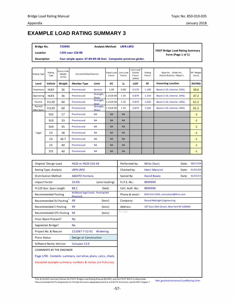
Bridge Load Rating Manual Topic No. 850-010-035
Appendix January 2018
-57-
EXAMPLE LOAD RATING SUMMARY 3
Bridge No.
Location
Description
Level Vehicle Weight Member Type Limit DC LL LLDF RF RATING
Inventory HL93 36 Service 1.00 0.80 0.570 1.100 39.6
Operating HL93 36Strength,
Shear1.25/0.90 1.35 0.870 1.310 47.2
Permit FL120 60Strength,
Axial1.25/0.90 1.35 0.870 1.020 61.2
Permit
Max SpanFL120 60
Strength,
Shear1.25/0.90 1.35 0.870 1.020 61.2
SU2 17 NA NA NA -1
SU3 33 NA NA NA -1
SU4 35 NA NA NA -1
C3 28 NA NA NA -1
C4 36.7 NA NA NA -1
C5 40 NA NA NA -1
ST5 40 NA NA NA -1
Date: 08/17/59
Date: 01/01/64
Date: 02/23/15
This 12-01-2017 summary fo llows the FDOT Bridge Load Rating M anual (BLRM ), and the FDOT BM S Coding Guide.
Unsealed example summary; numbers & names are ficticious.
Company: 99
Miles Davis
David Bowie
Checked by:
fdot.gov/maintenance/LoadRating.shtm*Recommended SU Posting levels for Florida SU trucks adequately restricts AASHTO SU trucks; see BLRM Chapter 7.
Phone & email:
Conspan 13.0Software Name, Version
COMMENTS BY THE ENGINEER
Address: 207 East 30th Street, New York NY 100000
P.E. Seal
213387-7-52-01 Widening
Segmental Bridge?
Plans Status
Project No. & Reason
99 (tons)
No
Page 1/90. Contents: summary, narrative, plans, calcs, check.
Design or Construction
Impact Factor 33.0% (axle loading)
(feet)
#999999
#999999
FL P.E. No.:
Cert. Auth. No.:FL120 Gov. Span Length 88.2
Legal
Prestressed
Prestressed
Prestressed
Henri Mancini
Original Design Load
Rating Type, Analysis
Distribution Method AASHTO Formula
Prestressed
Prestressed
Prestressed
Prestressed
Prestressed
Beam 2-10, Interior, 30%L
Beam 2-10, Interior, 30%L
Prestressed
Prestressed
Prestressed Beam 2-10, Interior, 50%L
Governing Location
Beam 2-10, Interior, 30%L
LRFR-LRFDAnalysis Method:729999
Rating
Factor
RF∙Weight
(tons)
Span No. - Girder No.,
Interior/Exterior, %Span∙L
FDOT Bridge Load Rating Summary
Form (Page 1 of 1)
Gross Axle
Weight
(tons)
Dead Load
Factor
Live Load
Factor
Live Load
Distrib.
Factor
(axles)
M oment/Shear/Service
I-295 over CSX RR
Four simple spans: 47-89-89-48 feet. Composite prestress girder.
Rating TypeRating
Type
LRFR-LRFD
Recommended Posting
Recommended SU Posting*
Recommended C Posting
Recommended ST5 Posting
Floor Beam Present?
Round Midnight Engineering
850-414-5200, [email protected]/Above legal loads. Posting Not
Required.
No
99 (tons)
HS20 or HS20-S16-44 Performed by:
Sealed By:
(tons)

Bridge Load Rating Manual Topic No. 850-010-035
Appendix January 2018
-58-
SYNOPSIS OF SIGNIFICANT REVISIONS, 2015
The 2015 FDOT Bridge Load Rating Manual rewrote the 2014 Manual. The organization
and intent was largely retained. However the word count was reduced significantly, and
the following changes were significant:
1. Add an updating procedure, for Technical Revisions.
2. Revise prestress Operating and Permit ratings to Strength, not Service. However
retain Service for prestress exhibiting distress or corrosion.
3. Remove the prestress Service I Lower Tendon Limit for LFR and LRFR-FL120.
See commentary at C6A.5.4.2.2b.
4. Clarify LRFD prestress shear capacity. Either use the General Method per LRFD,
or the “Simplified” method (ACI as modified by LRFD).
5. Narrow LFR and ASR. Exclude LFR and ASR from spans exceeding 200ft.
6. Require Legal Load assessments for LFR and ASR, regardless of the Design
Operating Rating.
7. Simplify system factors for steel bridges; do not apply different system factors to
different spans on the same bridge unit.
8. Simplify culvert analysis by providing criteria for wall assessments.
9. Remove requirements that older culverts be appraised by LFR. The 2013 LRFD
Interims broadened the effective strip width, and LRFR is now similar to LFR.
10. Describe load rating deliverables, and specify the mechanics of their submission
and adoption (Chapter 2—Process).
11. Specify what a load rating is, its minimum contents.
12. Simplify segmental analysis. First, for all Design Operating, Legal Operating, and
Routine Permit ratings, use γLL.Service = "0.90 SL," and a single-lane multiple
presence factor of 1.0 (consistent). Second, use Inventory Service I transverse
3∙√fc∙psi, for all environments, which coheres with LRFD 5.9.4.1.2-1, and redacts
slightly aggressive 6∙√fc∙psi (conservative, and consistent). Third, redact step-by-
step instructions (see Volume 10 A: Load Rating Post-Tensioned Concrete
Segmental Bridges, now somewhat outdated). Finally, redact specific instructions
for shear in segmentals (defer to the latest LRFD).

Bridge Load Rating Manual Topic No. 850-010-035
Appendix January 2018
-59-
SYNOPSIS OF SIGNIFICANT REVISIONS, 2016
The 2016 FDOT Bridge Load Rating Manual largely retains the 2015 Manual. The
following changes are notable:
1. Chapter 2—Process: Definition, Complete Load Rating. Add a provision for digital
delivery. Specify “unlocked,” and say why.
2. Chapter 2—Process: Table 2-1—Existing Bridges. For load rating reviews
coincident to bridge inspections, change the location of the note documenting the
review from “Structure Notes” to “Inspection Notes.” Additionally, remove “the
results are, by inspection, reasonable” as vague.
3. Chapter 6—Load Rating Analysis: 6A.5.12—Rating of Reinforced Concrete Box
Culverts. Rewrite the subsection, provide guidance, and link to an example.
SYNOPSIS OF SIGNIFICANT REVISIONS, 2017
1. 6A.5.7—allow simplified distribution for flat slab beams.
2. 6.1.5.2—explicitly require that straddle bents be analyzed.
SYNOPSIS OF SIGNIFICANT REVISIONS, 2018
1. 7.1—Posting, General. Add provisions to restrict AASHTO SHV-SU trucks.
2. 7.2—Posting, State-Maintained Bridges. Simplify.
3. 6B.5.3.3—Prestressed Concrete. Where RFLFR.HS20.Operating < 1.67, use LRFR.
4. 6A.5.11—Rating of Segmental Bridges. Revise load factor and stress tables.
5. Update and correct code references throughout.