Embed Size (px)
Citation preview

DRAFT FOR COMMENT
Flood Penetration Seal Performance
at
Nuclear Power Plants
Draft Methodology for Testing and
Evaluating the Performance of Flood
Penetration Seals
Task 1.2
of
Contract No.: NRC-HQ-60-15-C-0010
Provided To:
U.S. Nuclear Regulatory CommissionOne White Flint North
11555 Rockville Pike
Mailstop 03-E17A
Rockville, MD 20852-2738
Provided By:
Fire Risk Management, Inc. 1 Front Street
Bath, ME 04530
207/442-7200
13 February, 2018

DRAFT FOR COMMENT
Development of Draft Test Methodology for Flood Penetration Seal Performance i
Table of Contents
INTRODUCTION ....................................................................................................................................... 3
DISCUSSION .............................................................................................................................................. 3
Research of Flood Penetration Seal Testing .......................................................................................... 4
Flood Penetration Seal Performance Criteria ...................................................................................... 5
Flood Seal Testing Methodology Development ..................................................................................... 5
SUMMARY ........................................................................................................................................................ 6
ENCLOSURE 1 – Draft Test Methodology for Flood Penetration Seal Performance................E-1
DRAFT FOR COMMENT
Development of Draft Test Methodology for Flood Penetration Seal Performance 3
INTRODUCTION
The March 2011 accident that occurred at the Fukushima Daiichi nuclear plant in Japan
highlighted the potential damage that can be caused as the result of a significant flooding event.
Many of the commercial nuclear power plants (NPPs) in the U.S. are known to be located in
areas that are subject to potential flooding events of varying degrees of severity. Equally,
flooding damage is not restricted to an external event. Due to the high volume of water that is
used inside NPPs for cooling, fire suppression, and other auxiliary systems, the potential exists
for flooding to occur within a plant resulting from damage to internal piping. Areas within NPPs
that may contain equipment/systems that are important to safety and that have been identified as
being susceptible to flooding damage must be properly protected, which may include the need for
the walls and/or floor/ceiling assemblies that bound these areas to be designated as “flood
barriers.” As such, any penetration(s) through a barrier that is designated to be flood-resistant
must also be designed and installed to mitigate the potential for water intrusion through the
penetration opening.
Commercial NPPs throughout the country have identified barriers within their facilities that must
be designed to mitigate the potential spread of flooding. Although penetration seal assemblies
and materials are being installed by the NPPs to prevent or limit the passage of water through any
penetration openings in these flood barriers, no standard means for testing and rating the flood-
mitigation performance of these assemblies/materials currently exists.
As part of an overall effort to evaluate and quantify the expected performance of flood
penetration seal assemblies, including types and configurations that are currently being credited
by NPPs as part of their flood mitigation strategies, the NRC commissioned a research task to
develop a flood penetration seal testing methodology that could provide background knowledge
and testing insights into how to physically test and measure the performance of those seals that
are used (credited) at NPPs. The initial sub-task of this research effort, Task 1.1, included a
review of the various types of flood penetration seals that are currently being credited by NPPs in
the U.S. to support their flood mitigation strategies. The results of that sub-task will be used
when developing the Test Plan that will support flood testing of candidate penetration seal
assemblies/materials during Task 2 of the research program. The second sub-task, Task 1.2, of
the research program is to develop a draft test methodology for conducting the flood mitigation
testing during Task 2. This report summarizes the process used in supporting the development of
the draft test methodology for evaluating flood penetration seal assemblies and materials.
DISCUSSION
The overall objective for Task 1.2 is to develop a draft test methodology that can be potentially
used to evaluate the flood mitigation performance of the different types of penetration seal
assemblies that are, or will be, installed in barriers within commercial NPPs and are designed to
prevent the intrusion of water into specific areas of the plants. This report outlines the general
process used to develop a draft test methodology that will then be used during Task 2 of the NRC
research project. The primary intent for the Task 2 testing is not to assess the actual performance

DRAFT FOR COMMENT
Development of Draft Test Methodology for Flood Penetration Seal Performance 4
of the candidate seal assemblies, but to “test the test methodology” and ensure that it provides the
necessary methods to adequately evaluate the flood mitigation performance of all types of seal
assemblies and materials. However, based on the results of Task 1.1, a number of candidate seal
assemblies/materials that were noted as being prevalent within existing flood barriers in NPPs
will be selected for inclusion in the testing phase, which will provide some insight as to the
performance characteristics of those assemblies/materials.
Research of Flood Penetration Seal Testing
Included within the original tasking from the NRC to develop a draft test methodology for
evaluating flood mitigation performance, was a desire to generally follow similar methodology
used in performing the fire-resistance testing of penetration seal assemblies. The initial literature
search for existing test methods/protocols/procedures focused on researching any documents that
were related to testing for the performance of flood barrier systems. However, a review of a
number of standard fire test methods for penetration seal assembles was also conducted to
evaluate potential candidates for use as a “template” in formatting and configuring the flood
testing document; with the general premise being to follow a generally accepted format that
would be familiar to industry.
The research for existing, applicable flood testing methodologies yielded very little pertinent
information. Although UL 1479, Fire Tests of Through-Penetration Firestops, does include a
section (6A) for evaluating water leakage, this test does not provide adequate flexibility or data to
effectively evaluate the flood mitigation performance of a wide range of penetration seal
assembly/material types, nor would it support performance evaluation over a wide range of
applications to which the assemblies would be exposed when installed in NPPs. The UL test
requires seal assemblies to be exposed to three (3) feet of water (head) pressure for a set period of
time, typically 1 to 3 hours, to obtain a “W” rating. Factory Mutual (FM) has published an
Approval Standard for Flood Abatement Equipment, but this document primarily addresses the
barriers themselves, with no testing specific to penetration seals. The main focus for this
document is earthen dikes used to contain flood waters.
Nuvia Corporation, a manufacturer of flood penetration seal assemblies/materials and a member
of the NRC flood testing research team, has been performing flood-resistance testing of their
specific devices/materials for a number of years. Although the general configuration of the test
apparatus used by Nuvia formed the basis for the template included in the draft test methodology
for the NRC, their test procedure was evaluated as not having sufficient flexibility to support the
flood mitigation performance testing needs of the NRC. Additionally, the Nuvia pass/fail criteria
for their components are based on “no-leakage” through the penetration.
In addition to UL 1479, ASTM E814, the Standard Test Method for Fire Tests of Penetration
Firestop Systems, was also reviewed for potential applicability as a template for the draft flood
test methodology. Subsequent to the evaluation of the various documents reviewed, ASTM E814
was judged as having a format that would best lend itself in supporting the draft flood test
methodology. Additionally, given the wide use and acceptance of this standard throughout the
testing industry, it represents a format that would be familiar to most testing facilities that might
be used to perform the testing of flood penetration seal assemblies in the future. The use of

DRAFT FOR COMMENT
Development of Draft Test Methodology for Flood Penetration Seal Performance 5
ASTM E814 was as a template only. This draft test methodology is not intended to be an
approved industry-consensus standard.
Flood Penetration Seal Performance Criteria
Initial drafts of the test methodology included the potential for specific pass/fail criteria; similar
to the fire testing standards used to quantify the fire resistance performance of penetration seal
assemblies. A primary function for the data resulting from the testing of flood penetration seals
will be to support input to probabilistic risk assessments (PRAs) for flooding being performed at
NPPs. It has been noted that a successful flood risk mitigation strategy for many plants will not
necessarily be dependent upon “no leakage” through the penetration seals in their designated
flood barriers. The main goal for this draft test methodology is to provide the ability to quantify
the expected flood mitigation performance of the different types of seal assemblies and materials
that are being, or could be, used in flood barriers. For this reason, no specific pass/fail criteria are
included for the draft test methodology. The results of testing performed using this methodology
may be used as a starting point for developing a performance-based approach toward flood
damage risk assessment associated with systems/equipment protected by flood barriers. However,
manufacturers of penetration seal assemblies may also gain insights from this test methodology
as to how to quantify the specific performance, including limitations, associated with their
specific design/materials. Future test development beyond this research project could be used to
develop a performance “rating” for their product(s) that allows potential users to determine what
device/product can best support the specific flood-mitigation characteristics needed to maintain
adequate flood protection of their facility(ies); e.g.; a seal assembly is rated as having “X”
leakage rate, when exposed to “X” water (head) pressure, for “X” duration. When used in this
manner, it would be up to the Manufacturer to specify the flood exposure parameters/limits.
Flood Seal Testing Methodology Development
Using a basic format and approach that is similar to that of ASTM E814, a draft test methodology
has been developed that provides a potential testing approach for performing flood testing of
penetration seal assemblies. The draft methodology provides defined terminology and basic
testing methods that can be utilized when performing flood testing. The intent for the test
methodology is to provide a level of confidence that the results obtained at different testing
facilities could potentially be comparable and consistent with one another. The test methodology
provides information for both the design of the test apparatus and the environment within the
facility where the apparatus is housed. Equally, information regarding the conduct of the test,
including any potential conditioning or curing of the sample assembly(ies), and the data that must
be recorded during the test are also provided by this methodology.
A draft of the test methodology is provided as Attachment 1 to this report. This draft (edition) of
the test methodology will be used during the Task 2 testing phase of the NRC research program.
The primary function of the testing phase is to “test the test methodology” and assess its
flexibility in adequately supporting the testing of all types of seal assemblies/materials. Any
weaknesses, limitations, or other areas of improvement with the draft test methodology that are
identified during the Task 2 testing will be incorporated into the final edition of the test
methodology that will be submitted at the end of the research program.

DRAFT FOR COMMENT
Development of Draft Test Methodology for Flood Penetration Seal Performance 6
SUMMARY
The development of the draft test methodology for flood mitigation by penetration seal
assemblies represents the completion of Task 1 of the NRC Flood Penetration Seal Performance
research project. Specifically, this draft methodology is the primary deliverable for Task 1.2 and
will be used to perform the actual, limited flood penetration seal testing during the second phase
(Task 2) of this research program. Based on the results and observations made during Task 2, the
draft test methodology may be modified to incorporate specific changes to improve or correct
any deficiencies identified. The final test methodology will be incorporated as part of the
deliverable for Task 3.

DRAFT FOR COMMENT
Draft Test Methodology for Flood Penetration Seal Performance E-1
ENCLOSURE 1
Draft Test Methodology for Flood Penetration Seal Performance

DRAFT FOR COMMENT
Draft Test Methodology
* Indicates additional, related explanatory material can be found in Appendix B. 1
INTRODUCTION
This test methodology describes procedures for testing and quantifying the flood mitigation
performance of penetration seal assemblies intended for installation in flood barriers. The
proposed approaches and procedures described by this test methodology are not official NRC
guidelines, but rather serve as a starting point for this performance-based research effort. The
results from this research effort, including the final test methodology, may potentially be used as
a framework for the development of an industry consensus standard.
Resulting from the events and subsequent lessons learned associated with the accident that
occurred in March 2011 at the Fukushima Daiichi nuclear power plant, the NRC implemented a
program to assess and evaluate the flooding exposures at all nuclear power plants (NPPs) within
the U.S. The Fukushima event demonstrated the severe damage that can result during a flooding
event if NPPs are not properly protected. Unlike the requirements needed to qualify penetration
seal assemblies that are to be installed in fire-rated barriers, no standardized test method currently
exists within the U.S. industry to test and qualify penetration seal assemblies for flood resistance.
Although some evaluations have been performed by a few NPPs to evaluate the capabilities of
specific seal assemblies to withstand the effects of flooding, including the use of some
rudimentary testing, most penetration seal assemblies in use at NPPs have not been specifically
tested, including the use of a standardized methodology, to evaluate their ability to withstand
flood effects.
The spread of flood water into a building or between compartments of a building, either resulting
from an external environmental event or from the damage to an internal water distribution
system, typically occurs due to the structural failure of a barrier or through openings installed
within a barrier. It is common to support the distribution of services throughout a facility for
openings to be made in barriers that are required to restrict the potential spread of flood water to
allow the passage of penetrating items, such as piping, cables, conduit, duct banks, etc. from one
building compartment to the next. This draft test methodology is describes a performance-based
approach for evaluating the penetration assemblies designed to be installed in flood barriers to
prevent or restrict the passage of water through the barrier.
1. Scope of Test Methodology
1.1* The requirements of this test methodology are applicable to through-penetration seal
assemblies of various materials and construction that are intended for use in flood barriers, such
as walls and floor/ceiling assemblies, installed in NPPs.
1.2 Although the test methodology is a demonstration product of the NRC flooding research
program, it was drafted as if for use by at least two (2) sets of distinct end users and functions:
1.2.1 Manufacturers; to develop performance-based parameters and/or limitations
associated with a specific type of seal assembly/material, and

DRAFT FOR COMMENT
Draft Test Methodology
* Indicates additional, related explanatory material can be found in Appendix B. 2
1.2.2 NPPs and/or Regulators; to develop performance-based data for specific flood
penetration seal assemblies/materials used in specific configurations, with specific flood
exposure parameters, for use in supporting flood probabilistic risk assessments (PRAs).
1.3* It is not the specific intent of this test methodology to establish “pass/fail” criteria. The
methodology outlines a performance-based approach to evaluate flood mitigation properties
associated with specific penetration seal assemblies/materials when exposed to specified flood
event parameters; including water pressure(s) and duration.
1.4 The testing methodology of through-penetration seal assemblies consists of direct exposure
of test samples to a specified water pressure. The magnitude of the water (head) pressure to
which the individual seal assemblies are tested will be specified by its Manufacturer or end user.
The evaluation of each through-penetration flood seal assembly will be based on:
1.4.1 Restriction of water transmission (leakage) through the assembly,
1.4.2 Performance over the required exposure duration, and
1.4.3 Compatibility of assembly to the proposed environment, which can include aging
characteristics of assembly materials.
1.5 This method of testing will include exposure to water (head) pressure for a specified
duration to mimic flooding conditions to which the assembly(ies) may be exposed during an
anticipated flood event. This flood testing is to determine the ability of the seal configuration,
material, and or device to resist the passage of water under the designated pressures and duration.
1.6* This test methodology is used to quantify the performance of flood seals when exposed to
water pressure. The test methodology is not intended to quantify the performance of flood seals
when subjected to other forces, such as the failure of cable or pipe support systems or impact
from falling or floating debris.
1.7 The intent for this test methodology is to develop data to determine the flood mitigation
performance of penetration seal assemblies; of all types (materials, configurations, etc.) that are
appropriate for use in flood barriers having specific, analyzed flood-resistance performance
parameters.
1.8 The (head) pressure values stated in pounds per square inch (psi) and volumetric flow
(leakage) rates stated in gallons per minute (gpm) are to be considered as the standard units.
Values used in expressing test pressure, represent the increased pressure difference above
standard, ambient atmospheric pressure, to which a candidate seal assembly is exposed during a
test cycle. Any values given in parentheses are mathematical conversions to international (SI)
units.
1.9 This test methodology is developed to quantify and describe the response of penetration
seal assemblies, products, and/or materials that are exposed to water pressure under controlled
conditions, but does not by itself incorporate all variables and or factors that could influence with
ultimate performance of a seal assembly when exposed to actual flood conditions.

DRAFT FOR COMMENT
Draft Test Methodology
* Indicates additional, related explanatory material can be found in Appendix B. 3
1.10 It is not the intent of this test methodology to determine the performance capabilities of a
flood seal subsequent to being exposed to a flooding event. It is the responsibility of the user of
this test methodology, or the data resulting from testing performed in accordance with this test
methodology, to evaluate the condition of any flood seal, including the potential for degradation,
whether visible or not, after exposure to an actual flooding event.
1.11 All penetration seal assemblies and penetrants are to be installed in the test apparatus in the
specific configuration(s) that is reflective of their intended as-built (or planned) configuration(s)
in NPPs.
1.12 It is the intent for this test methodology that all testing will be performed using fresh water.
If the penetrations being tested are to be qualified for exposure to seawater environments, a
conversion (reduction) factor of 0.975 shall be applied to the recorded test (head) pressures to
account for the difference in the average density (weight) of seawater as compared to fresh water
[0.445 psi per foot of seawater versus 0.433 psi per foot of fresh water]. Any potential
compatibility limitations associated with exposure of the seal assembly/materials to seawater
must be specified by the Manufacturer.
2 General
2.1 Units of Measurement
2.1.1 Values listed without the use of parentheses are the requirements of this test
methodology. Values in parentheses are for use when the metric (SI) system of units is desired.
2.2 Glossary
2.2.1 Ambient Temperature: The average air temperature surrounding the test apparatus.
2.2.2 Fire Penetration Seal: A fire-resistant seal assembly or material designed to maintain the
fire-resistive integrity of the barrier in which it is installed.
2.2.3 Flood Penetration Seal (FPS): A flood-resistant seal assembly or material designed to
maintain the flood rating of the barrier in which it is installed. Barrier penetrations to be
protected may consist of either through-penetrations or membrane penetrations.
2.2.3.1 Through-barrier penetration: A penetration that extends completely through the
flood barrier.
2.2.3.2 Membrane penetration: A penetration that passes through part of the barrier, but
not the entire barrier. Some examples are outlet boxes, drains, or conduit that leads
from a back-box to the space above the ceiling. Flood seal assemblies for membrane
penetrations will be tested in the same manner as that used for through-penetrations.
2.2.4 Flood Penetration Seal Configuration: The physical arrangement of both the penetration
itself and the materials and/or components within the barrier penetration; including both the
flood seal and penetrants.
2.2.5 Independent Testing Laboratory: A laboratory which has been determined to have the
capabilities and qualifications to properly perform the testing outlined in this test methodology

DRAFT FOR COMMENT
Draft Test Methodology
* Indicates additional, related explanatory material can be found in Appendix B. 4
and that has no financial or technical conflict of interest associated with any of the sample flood
penetration seal assemblies/materials being tested.
2.2.6 Internal Conduit Seal (ICS): A material, combination of materials, or pre-manufactured
device installed inside of a conduit. Internal conduit seals are typically installed at the first access
point in the conduit from the barrier being penetrated. Access points include pull boxes, junction
boxes, or an open-end if the conduit terminates in space.
2.2.7 Leakage: The passage of water through or between the flood seal assembly and the
surface interface with the penetrated barrier and/or penetrating item (pipe, conduit, etc.).
2.2.8 Leakage Rate: The volumetric rate at which water is measured as leaking through or
around the sample flood seal assembly/material; measured in units of gallons per minute (gpm)
or alternatively, liters per minute (lpm).
2.2.9 Sample Test Deck: The wall/floor test assembly with through-penetration flood seal
assembly(ies) or material(s) installed within the sample penetration(s); including penetrants for
which each seal assembly is designed to support. The size and configuration of the penetration(s)
in the test sample will be dependent upon the specific seal assembly to be tested and qualified; as
installed in accordance with their individual Manufacturer’s specifications.
2.2.9.1 Discussion: Penetrating items may include, but not be limited to; pipes, conduit,
cables, cable trays, etc.
2.2.10 Test Apparatus: The equipment unto which a sample test deck is mounted or installed.
The test apparatus is designed to subject a sample penetration seal assembly(ies) to water
pressure; at a specific pressure and duration. The tested pressure represents the difference in
pressure (Δp), as measured between the ambient environment and the exposed side of tested seal
assembly, which is to be expressed in pounds per square inch (psi) or alternatively in SI units of
kilopascals (kPa).
3. Test Equipment
3.1 The test apparatus will include a pressure chamber that will consist of a sealed vessel
capable of producing the simulated water pressures associated with an expected flooding event to
which the sample seal assembly(ies) is (are) expected to withstand. The pressure chamber shall
be open on the side to which the sample test deck is to be installed. The pressure chamber will be
provided with a mounting flange and gasket, or similar arrangement, to provide a watertight seal
with sample test deck.
3.2 The pressure chamber may be designed for operation with the sample test deck in either a
vertical or horizontal configuration. [Note: For consistency and ease of (head) pressure
measurement at the level of each penetration, the horizontal mounting is typically preferred.]
The area (size) of the open side of the pressure chamber shall, at a minimum, be sufficient to
accommodate the largest penetration for which a seal assembly is to be tested.
3.3 The pressure chamber is to be provided with a water fill connection that is designed to
ensure that all flood seal assemblies installed in the test sample are fully immersed in water
DRAFT FOR COMMENT
Draft Test Methodology
* Indicates additional, related explanatory material can be found in Appendix B. 5
throughout the test duration. This includes the capability for make-up water to be provided into
the chamber during testing to allow for water that may be lost due to leakage through or around a
seal assembly. If the pressure chamber is not designed to be completely flooded with water
throughout the test, a water level indicator must be included in the pressure chamber design.
3.4 The design of the test apparatus is to include the capability to deliver and maintain a
specified water pressure, whether static or variable, on the exposed side of the test sample. The
test apparatus shall have the capability to increase the water pressure within the pressure
chamber, on the exposed side of the sample test deck, from ambient (static head pressure from
the water in the chamber) to the maximum test pressure as required to mimic the expected flood
event for which the sample is being evaluated/qualified.
3.5 The pressure chamber is to be provided with an attached pressure gauge to indicate
internal water pressure, along with having an internal pressure sensing device that is connected
to a data acquisition system that will automatically record the internal pressure within the
pressure chamber throughout the test duration. Both the external pressure gauge and internal
sensor should be located as close to the level of the penetrations as possible.
3.6 If air pressure is used to produce the test pressures and will partially fill the pressure
chamber, two external pressure gauges are to be provided; one that is located within the water
space at (or near) the level of the penetrations and one that is located within the air space of the
chamber. This configuration will also require that a water level sensor be installed within the
pressure chamber to ensure an adequate water level is maintained.
3.7 The test apparatus must include the capability to capture and record any leakage through
the individual penetration seal assembly(ies) on the non-exposed side of the test sample. The data
acquisition system must have the capability to record the volumetric leakage rate through any
individual seal assembly throughout the duration of the test.
3.8 Given that the potential for leakage through the various seal assemblies being tested
exists, the test apparatus must have the capability to provide make-up water to the pressure
chamber.
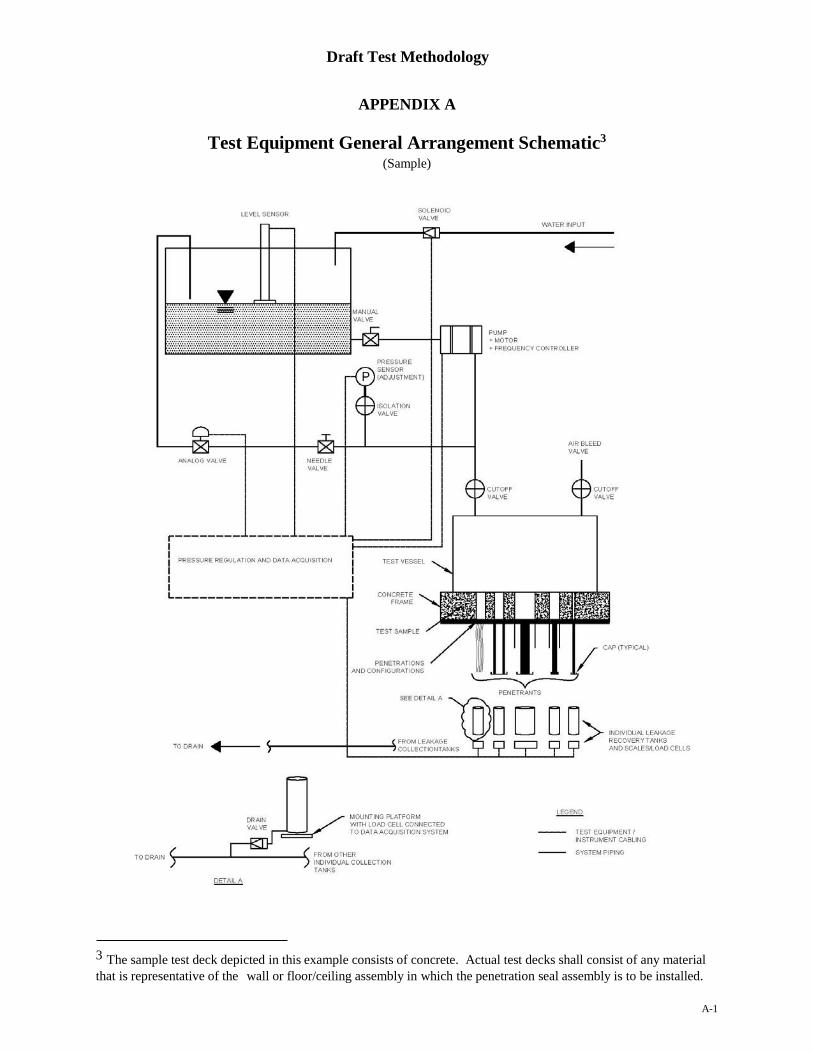
3.9 A diagrammatic sketch of a typical configuration for a test chamber and its associated test
and support equipment is included in Appendix A to this test methodology.
4 Test Sample
4.1 The individual penetration seal assembly(ies) is (are) to be installed in the sample test
deck, which is to be installed against, and affixed to, the pressure chamber. The sample test deck
must be designed to allow for a watertight seal to be maintained at the interface with the pressure
chamber.
4.2 The design of the sample test deck must ensure that all installed penetrations are located
within the opening of the pressure chamber, while allowing sufficient additional area around the
perimeter of the pressure chamber opening to facilitate attachment to the pressure chamber
mounting flange (or other attachment arrangement), along with ensuring proper strength of the
sample test deck to withstand the anticipated pressure load.

DRAFT FOR COMMENT
Draft Test Methodology
* Indicates additional, related explanatory material can be found in Appendix B. 6
4.3 The specific material design and specifications for the sample test deck should be based
on the design of the flood barrier, including its intended maximum flood resistance rating, for
which the seal assembly(ies) is (are) designed to support. If it is intended that penetrations
through a flood barrier are to be “sleeved”, then the design of the test sample must include the
installation of sleeves when being constructed. Proper monitoring and inspection during the
performance of the flood testing is necessary to ensure that an improperly constructed sample
test deck, which results in leakage between a sleeved penetration and the sample test deck
material or other leakage paths, such as cracks, doesn’t result in the inadvertent assignment of
additional leakage volume (rate) to a seal assembly.
4.4 Each penetrating item containing hollow spaces, such as pipes and conduit, through
which water can leave the chamber shall be sealed on both the exposed and unexposed sides to
prevent any water leakage through the penetrant. If a penetrant is designed to be installed in a
barrier credited for flood protection on one side only, the unexposed side of the penetration is not
to be sealed during testing.
4.5 Construction of the flood penetration seal assembly shall be representative of an “as-
built” configuration, including all pipes, conduits, cables (percent fill), required supports, etc.
and be in accordance with the applicable Manufacturer’s specifications and instructions.
4.6 Install through-penetrating items so that they extend a minimum of 12 inches (305 mm)
on both the exposed and unexposed sides of the test sample. If penetrating items are designed to
be provided with bracing during field installation, the penetrants will be extended to a sufficient
length on either side of the test sample to accommodate the required bracing. Install membrane
penetrating items to match field installation configuration.
4.7 Construct the sample test deck to mimic the field installation for both the wall/floor
materials and those of the penetration seal assembly. Ensure sufficient cure time is provided for
all materials to achieve their design strength prior to the commencement of testing in accordance
with standard construction practices, for the wall/floor materials if concrete, mortar, etc. is used,
and Manufacturer’s instructions for the seal materials.
4.8 Condition the test sample, including all installed penetration seal assemblies/materials, to
provide a moisture content that is representative of that which is anticipated for field
construction. For the purposes of standardization, this condition is considered to be achieved
when the seal assembly materials have a moisture content corresponding to drying to equilibrium
with air in the range of 50% to 75% relative humidity at 73 (+/- 5)°F (23 (+/- 3)°C). If, however,
due to the nature of the material(s) and/or their construction configuration, this cannot be
achieved, then these requirements may be waived, except as to the attainment of the required
strength as outlined in 4.7 above.
5 Conduct of Flood Testing
5.1 Flood tests should be performed within an environmentally controlled area to minimize
any variables associated with changes in ambient conditions that might impact the test results.
Ambient temperature and pressure within the test facility should be recorded at the start of each

DRAFT FOR COMMENT
Draft Test Methodology
* Indicates additional, related explanatory material can be found in Appendix B. 7
test cycle and monitored throughout the duration of the test. It is recommended that the ambient
temperatures surrounding the test equipment be maintained between 50°F (10°C) and 90°F
(32°C). If it is anticipated that a penetration seal assembly is to be exposed to freezing or
excessively warm temperatures, which the Manufacturer has indicated may have a detrimental
impact on seal performance, additional testing and/or evaluation may be necessary to quantify
any performance reduction.
5.2 Prior to test commencement, the specific design/configuration of the test sample,
including each seal assembly installed, is to be recorded; including, but not limited to, the
following information:
5.2.1 Sample Test Deck (material) description and dimensions
5.2.2 Seal Assembly/Material Manufacturer(s)
5.2.3 Seal assembly / material description(s)
5.2.4 Penetration size (dimensions or diameter)
5.2.5 Penetrant(s) description, including fill density1 as appropriate. For seals tested without
any penetrating items, the fill density should be recorded as “zero.”
5.3 Do not commence flood testing until the sample test deck has developed sufficient
strength, as appropriate for its construction material(s) and standard industry practice, to retain
securely in position the materials and/or devices that are used to seal the penetrations.
5.4 Unless the test apparatus is specifically designed to utilize air pressure within the test
chamber to regulate the test pressure; prior to commencing the flood testing, ensure all air is
vented from the pressure chamber.
5.5 Maximum test pressure within the pressure chamber, and the rate at which it is achieved,
shall be based on the parameters needed to mimic a specific flood event or that specified by the
Manufacturer.
5.6 Visual inspections of the sample test deck are to be performed throughout the test cycle,
including subsequent to reaching the maximum test pressure, to determine if any leakage is
visible at the interface between the pressure chamber and the sample test deck and/or from any
location other than “through” a sample seal assembly being tested.
5.7 The water pressure to which the sample seal assemblies are exposed, including the rate at
which the pressure may be applied over the duration of the test, is to be recorded by the installed
data acquisition system.
5.8 The volumetric leakage rate through any individual penetration seal assembly is to be
recorded by the data acquisition system throughout the duration of the test.
5.9 The duration of each test is to be specified by the end user; whether by a Manufacturer to
qualify a specific penetration for exposure to a maximum pressure and/or duration, or to develop
performance data for specific assemblies/materials for use in supporting PRAs.
1 Fill density is the percentage of the available penetration opening area that is occupied by a penetrating item. For example, a
2-inch diameter pipe installed through a 4-inch diameter penetration would represent a fill density slightly in excess of 50%.
DRAFT FOR COMMENT
Draft Test Methodology
* Indicates additional, related explanatory material can be found in Appendix B. 8
6. Report
6.1 A detailed report of the performance of each flood penetration seal assembly installed in
the sample test deck shall be provided. At a minimum, the report shall include the following
information:
6.1.1 A description of the test apparatus, including photos or schematic diagrams, used in
performing the flood testing.
6.1.2 A detailed description of the sample test deck, including:
6.1.2.1 Materials of construction and a drawing that depicts geometry and dimensions,
along with locations of penetrations within the sample test deck, and
6.1.2.2 Installed seal assemblies; including manufacturer, type of assembly and/or
material, configuration (or link to specific penetration listed in 6.1.2.1 above),
penetrating items and any applicable fill density. Include drawings or pictures
depicting installed configuration of each seal assembly, along with photographs
during and following each test, as appropriate.
6.1.3 The relative humidity of the ambient environment during curing and testing of the test
sample and installed seal assemblies/materials, if applicable.
6.1.4 A summary of test results or print out from the data acquisition system. At a
minimum, this shall include pressure and leakage data as a function of test time
(duration) for each seal assembly.
6.1.5 Any observations and/or significant details regarding the test, including any issues
associated with the sample test deck and each penetration seal assembly tested;
documenting any leakage from either the pressure chamber/deck interface or
penetration assembly, any test apparatus faults or failures, etc.
6.1.6 A general summary that, as a minimum, outlines the following;
6.1.6.1 The rationale for the maximum test pressure used
6.1.6.2 The final test duration recorded for all seal assemblies. The overall test duration
may vary for each test, since the time of commencement of the actual test period
for individual seal assemblies may vary due the time needed for leakage rates to
stabilize.
6.1.6.3 The final performance of all seal assemblies for the test period. This should also
include an assessment of any leakage recorded through a seal assembly and any
changes in the rate of leakage observed throughout the test duration.
6.1.6.4 A statement regarding the flood resistance performance of each seal assembly,
inclusive of any leakage rate(s) associated with the assembly.2
2 Where flood penetration seals are to be exposed to seawater, the maximum pressure rating developed during the
testing using this methodology should be reduced by a factor of 0.975 to account for the difference in densities (weight)
between seawater and fresh water.
DRAFT FOR COMMENT
Draft Test Methodology
A-1
APPENDIX A
Test Equipment General Arrangement Schematic3
(Sample)
3 The sample test deck depicted in this example consists of concrete. Actual test decks shall consist of any material
that is representative of the wall or floor/ceiling assembly in which the penetration seal assembly is to be installed.
DRAFT FOR COMMENT
Draft Test Methodology
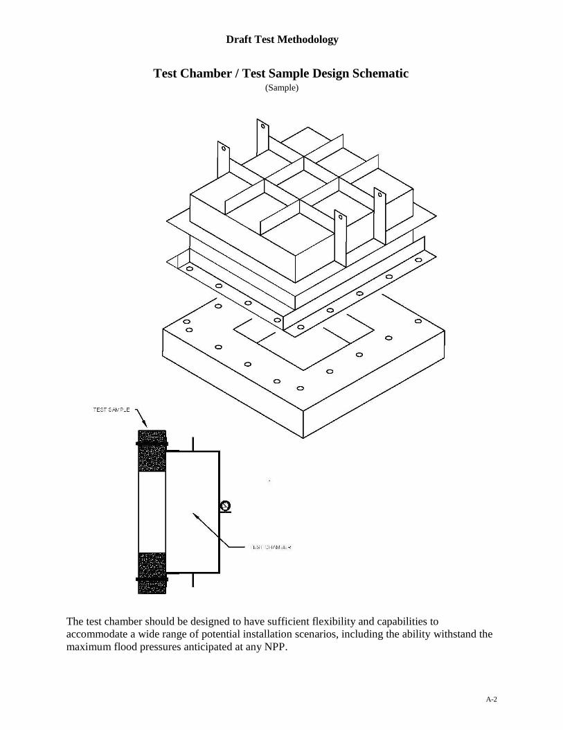
A-2
Test Chamber / Test Sample Design Schematic (Sample)
The test chamber should be designed to have sufficient flexibility and capabilities to
accommodate a wide range of potential installation scenarios, including the ability withstand the
maximum flood pressures anticipated at any NPP.

DRAFT FOR COMMENT
Draft Test Methodology
B-1
APPENDIX B
General Discussion of the NRC Flood Penetration Seal Test Methodology
B-1. Introduction
The March 2011 tsunami event that occurred at the Fukushima Daiichi nuclear plant in Japan
highlighted the potential damage that can be caused as the result of a significant flooding event.
Many of the commercial nuclear power plants (NPPs) in the U.S. are known to be located in
areas that are subject to potential flooding events of varying degrees of severity. Subsequent to
the Fukushima nuclear incident, the Nuclear Regulatory Commission (NRC) issued a request to
all operating NPPs in the U.S. for information pursuant to Title 10 of the Code of Federal
Regulations (CFR), Section 50.54(f), regarding the design-basis flood estimates used at NPPs.
Additionally, NRC staff performed a number of site surveys at NPPs that focused on flood
mitigation.
The results of internal NRC research regarding flood protection at NPPs identified the lack of
standardized test procedures or methodologies used by the Licensees to verify or quantify the
level of performance associated with specific flood seal assemblies installed in the penetrations
through flood barriers. Without a standard set of procedures or protocols to test and evaluate the
performance of the various flood seal types and configurations being used by the NPPs, it was
not possible to verify whether or not a specific penetration seal assembly could adequately
support the flood mitigation requirements at the various NPPs.
In the fall of 2015, the NRC implemented a research program to not only identify the type of
penetration seal assemblies and materials being used by NPPs in maintaining the integrity of their
flood barriers, but to develop a testing methodology that could be used to quantify the actual
flood mitigation performance of these and any other penetration seal assemblies that might be
proposed for use in flood barriers. This test methodology is not intended to be an NRC approved
standard test method, although results from this research effort (including the final test
methodology) may be used as a starting point or initial framework for the future development of
an industry consensus standard.
B-2. Applicability
This test methodology is designed to be applicable to any type of penetration seal assembly
and/or material that is intended for installation in a flood barrier. These flood seal
assemblies/materials are intended for use in openings in flood walls and floors, whether these
openings represent through-penetrations of the entire barrier or are penetrations through only one
portion of a membrane type barrier.
This test methodology does not apply to termination devices that are intended to provide
electrical, communication, or other circuitry at the surface of an assembly, and which are
evaluated as being an integral part of the assembly itself.
B-3 Criteria

DRAFT FOR COMMENT
Draft Test Methodology
B-2
This flood test methodology is intended to support the evaluation of the flood mitigation
performance of penetration seals that are designed to protect openings in barriers (walls/floors)
that have been otherwise credited as having a flood resistance rating in support of a flood
mitigation program at a commercial NPP.
This test methodology does not specify minimum performance criteria, such as exposure pressure
or duration, to which the seal assemblies must be exposed. It is understood that different
assemblies and materials will have varying properties that may make them more or less
susceptible to leakage when exposed to varying levels of pressure exerted on one side of the
penetration assembly. Different assemblies and materials may have greater pressure resistance
when installed in penetrations involving specific types of penetrants or be limited in the size of a
penetration that they may be able to support. As such, it will be the responsibility of the
individual Manufacturer or end user to determine the expected performance parameters
associated with a particular seal assembly being evaluated.
It has been evaluated that a successful flood mitigation strategy is not necessarily contingent
upon a need for all flood barriers to be completely watertight. As long as it is possible to quantify
potential leakage through a flood barrier, which can then be evaluated against the potential for
water removal capabilities during a flood event, it may be acceptable for some credited flood
barriers to only minimize water passage; versus completely prevent all leakage through a barrier.
However, such an evaluation must be performed on a case-by-case basis as part of a formal flood
risk evaluation, which can then determine which, if any, flood barriers can have some level of
leakage. For any specific barrier, the total allowable leakage rate, as determined by a flood risk
evaluation, cannot be exceeded by the aggregate leakage rate through any/all penetrations within
that barrier. This test methodology is intended to provide the data necessary to support such an
evaluation.
This test methodology is not intended to address any other potential leakage mechanisms for
penetration seal assemblies beyond exposure to specified water pressures for a specified duration.
This includes mechanisms such as impact from float debris, vibration due to seismic activity or
attached machinery, or aging. Although it is anticipated that some seal assemblies could be
exposed to “impact” damage from floating debris and seismic activity, there are too many
variables associated with such an event to develop a realistic simulation for inclusion in a
“standardized” testing methodology. Where such events need to be evaluated, those evaluations
should be separate from this test methodology and the following are provided as
recommendations to support those evaluations:
Impact Damage; it will be necessary to either develop a “scenario-specific” test, including
the test apparatus, to obtain impact performance data or provide a protective barrier around
the installed penetration(s) to mitigate any potential impact damage.
Vibration; Similar to fire-rated penetration seals, if the Manufacturer does not indicate that
a seal assembly/material has the ability to accommodate vibration or other movement of a
penetrating item, within specified limits, the penetrating item should be braced to the
penetrated barrier such that no movement between the penetrating item and the barrier

DRAFT FOR COMMENT
Draft Test Methodology
B-3
occurs.
Aging; the potential impacts on seal assembly due to “aging” effects are not part of this
methodology. If this is an issue of concern, the candidate seal assembly should be
subjected to any artificial aging protocols/procedures/techniques separately, prior to testing
the assembly for flood resistance.
B-4. Test Sample
The piping, cables, conduit, and other penetrating items anticipated for flood barriers shall be
representative of the field configurations for which the seal assembly is intended and the flood
resistance rating is desired.
The focus for this test methodology is the flood resistance of penetration seal assemblies and
materials. Although it is intended that the test sample include penetrations and penetrants,
including any supporting structures, that are representative of actual field installations (current or
planned), the tested configurations may not be representative of “worst-case” field conditions due
to the constraints and limitations associated with performing tests of this nature. For example,
testing of penetration seal assemblies intended for installation in walls with a test sample that is
mounted in a horizontal configuration may not reflect all potential movement of, or stresses on,
the penetrants that might be expected during exposure to a flood event.