Embed Size (px)
Citation preview

USER MANUAL
FLIR MODEL DM285 Imaging Multimeter with IGMTM and Bluetooth®

FLIR DM285 USER MANUAL Document Identifier: DM285-en-GB_AB 2
Table of Contents
1. ADVISORIES 5 1.1 Copyright 5 1.2 Quality Assurance 5 1.3 Documentation 5 1.4 Disposal of Electronic Waste 5
2. SAFETY 5 3. INTRODUCTION 8
3.1 Key Features 8 4. METER DESCRIPTION AND REFERENCE GUIDE 9
4.1 Front and Back Meter Descriptions 9 4.2 Function Switch Positions 10 4.3 Function Buttons and Navigation Pad 11
4.3.1 MODE Button Operation 11 4.3.2 OK Button/Navigation Pad Operation 12
4.4 Status Bar Display Icons 12 4.5 Other Display Icons 13
5. METER POWER 14 5.1 Powering the Meter 14 5.2 Auto Power OFF (APO) 14 5.3 Battery Type Selection 14
6. MENU SYSTEM 15 6.1 Using the Menu System 15 6.2 Main Menu Options 15
6.2.1 Image Mode Menu 15 6.2.2 Thermal Settings Menu 15 6.2.3 Gallery Mode 16 6.2.4 Advanced Functions Menu 16 6.2.5 General Settings Menu 16
7. GENERAL SETTINGS 17 7.1 General Settings Navigation 17
7.1.1 Diode SMART/CLASSIC 17 7.1.2 APO (Auto Power OFF) 17 7.1.3 Temperature units select oC/oF 17 7.1.4 Datalogger Sample Rate 17 7.1.5 Real-time Clock 17 7.1.6 Auto Hold / Data Hold 18 7.1.7 Coarse Resolution 18 7.1.8 Bluetooth® ON/OFF 18
FLIR DM285 USER MANUAL Document Identifier: DM285-en-GB_AB 3
7.1.9 Button-press tone ON/OFF 18 7.1.10 Battery type selection 18 7.1.11 Language selection 18 7.1.12 Delete all Datalogger readings 18 7.1.13 Delete all Stored Thermal Images 18 7.1.14 View HELP Screen 18 7.1.15 Viewing firmware, Bluetooth®, and Laser data 18
8. THERMAL IMAGING 19 8.1 Thermal Imager Basics 19 8.2 Thermal Imager Operation 20 8.3 Thermal Settings Menu (Color Palette, Emissivity, Laser Pointer, Crosshairs) 21 8.4 Image Mode Menu 22 8.5 Thermal Image Capture 22 8.6 Thermal Image Freeze (Data Hold) 22 8.7 Using the Multimeter in the IGMTM mode 22
9. MULTIMETER OPERATION 23 9.1 Auto/Manual Range Mode 23 9.2 Probe Connection Alert 23 9.3 Test Lead Holder Accessory 23 9.4 Out of Range Warning (OL) 24 9.5 Data Hold and Auto Hold 24
9.5.1 Data Hold Mode 24 9.5.2 Auto Hold Mode 24
9.6 Status Bar and Menu Icons 25 9.7 VFD (Low Pass Filter) 25 9.8 MAX-MIN-AVG mode 26 9.9 Peak Mode (AC Current and Voltage Measurements only) 26 9.10 Relative mode 26 9.11 Voltage and Frequency Measurements 27 9.12 Non-Contact Voltage Detector 28 9.13 Resistance Measurements 28 9.14 Continuity Test 29 9.15 Classic Diode Test 30 9.16 Smart Diode Test 31 9.17 Capacitance Measurements 32 9.18 Type K Temperature Measurements 33 9.19 Current and Frequency Measurements (A, mA, µA) 33

FLIR DM285 USER MANUAL Document Identifier: DM285-en-GB_AB 4
9.19.1 Test Lead Current Measurements (A, mA, and µA) 34 9.19.2 FLEX Clamp Adaptor Current and Frequency Measurements 36
10. DATALOGGER 37 10.1 Start Datalogging 37 10.2 Stop Datalogging 37 10.3 View Datalogger Sets 37 10.4 Delete Datalogger Sets 37 10.5 Transmit Datalogger Sets via Bluetooth® 37
11. BLUETOOTH® TRANSMISSION 38 12. APPENDICES 39
12.1 Emissivity Factors for Common Materials 39 12.2 Non-Uniformity Correction 39 12.3 Infrared Energy and Thermal Imaging Overview 40
13. MAINTENANCE 41 13.1 Cleaning and Storage 41 13.2 Battery Replacement 41 13.3 Fuse Replacement 41 13.4 Disposal of Electronic Waste 41
14. SPECIFICATIONS 42 14.1 General specifications 42 14.2 Thermal Imaging Specifications 43 14.3 Electrical Specifications 43
15. TECHNICAL SUPPORT 48 16. WARRANTIES 48

FLIR DM285 USER MANUAL Document Identifier: DM285-en-GB_AB 5
1. Advisories 1.1 Copyright © 2020, FLIR Systems, Inc. All rights reserved worldwide. No parts of the software including source code may be reproduced, transmitted, transcribed or translated into any language or computer language in any form or by any means, electronic, magnetic, optical, manual or otherwise, without the prior written permission of FLIR Systems. The documentation must not, in whole or part, be copied, photocopied, reproduced, translated or transmitted to any electronic medium or machine-readable form without prior consent, in writing, from FLIR Systems. Names and marks appearing on the products herein are either registered trademarks or trademarks of FLIR Systems and/or its subsidiaries. All other trademarks, trade names or company names referenced herein are used for identification only and are the property of their respective owners.
1.2 Quality Assurance The Quality Management System under which these products are developed and manufactured has been certified in accordance with the ISO 9001 standard. FLIR Systems is committed to a policy of continuous development; therefore, we reserve the right to make changes and improvements on any of the products without prior notice.
1.3 Documentation To access the latest manuals and notifications, go to the Download tab at: https://support.flir.com. It only takes a few minutes to register online. In the download area you will also find the latest releases of manuals for our other products, as well as manuals for our historical and obsolete products.
1.4 Disposal of Electronic Waste As with most electronic products, this equipment must be disposed of in an environmentally friendly way, and in accordance with existing regulations for electronic waste. Please contact your FLIR Systems representative for more details.
2. Safety Safety Notes
• Before operating the device, you must read, understand, and follow all instructions, dangers, warnings, cautions, and notes.
• FLIR Systems reserves the right to discontinue models, parts or accessories, and other items, or to change specifications at any time without prior notice.
• Remove the batteries if the device is not to be used for an extended period.

FLIR DM285 USER MANUAL Document Identifier: DM285-en-GB_AB 6
Warning Statements
• Do not operate the device if you do not have the correct knowledge. Incorrect operation of the device can cause damage, shock, injury or death to persons.
• Do not start a measuring procedure before you have set the function switch to the correct position. Failure to do so can cause damage to the instrument and can cause injury to persons.
• Do not change to the resistance mode when measuring voltage. This can cause damage to the instrument and can cause injury to persons.
• Do not measure the current on a circuit when the voltage increases to more than 1000 V. This can cause damage to the instrument and can cause injury to persons.
• You must disconnect the test leads from the circuit under test before you change the range. Failure to observe this warning can damage the instrument and cause bodily injury.
• Do not replace the batteries before you remove the test leads. This can cause damage to the instrument and can cause injury to persons.
• Do not use the device if the test leads and/or the device show signs of damage. Injury to persons can occur.
• Be careful performing measurements if the voltages are > 25 VAC rms or 35 VDC. There is a risk of shock from these voltages. Injury to persons can occur.
• Do not do diode, resistance or continuity tests before you have removed the power from capacitors and other devices under test. Injury to persons can occur.
• Be careful when performing voltage checks on electrical outlets. These checks are difficult because of the uncertainty of the connection to the recessed electrical contacts. You must not rely solely on this device when determining if the terminals are not “live”. There is a risk of electrical shock. Injury to person can occur.
• Do not touch expired/damaged batteries without gloves. Injury to persons can occur. • Do not cause a short circuit of the batteries. This can cause damage to the instrument
and can cause injury to persons. • Do not put the batteries into a fire. Injury to persons can occur. • Use extreme caution when the laser pointer is on. • Do not point the beam toward anyone's eye or allow the beam to strike the eye from a
reflective surface. • Do not use the laser near explosive gases or in other potentially explosive areas. • Refer to the CAUTION statement label (shown below) for critical safety information.

FLIR DM285 USER MANUAL Document Identifier: DM285-en-GB_AB 7
Cautions Do not use the device in a manner not specified by the manufacturer. This can cause damage to the protection provided.
This symbol, adjacent to another symbol or terminal, indicates that the user must refer to the user manual for further information.
This symbol, adjacent to a terminal, indicates that, under normal use, hazardous voltages may be present.
Double insulation.
UL listing is not an indication or a verification of the accuracy of the meter

FLIR DM285 USER MANUAL Document Identifier: DM285-en-GB_AB 8
3. Introduction Thank you for selecting the FLIR DM285 True RMS Digital MultiMeter with IGMTM (Infrared Guide Measurement) and Bluetooth®. The DM285 can measure voltage up to 1000V AC/DC and includes Low-Z (low impedance), VFD (low pass filter), and Smart/Classic Diode modes. This device is shipped fully tested and calibrated and, with proper use, will provide years of reliable service.
3.1 Key Features • 6000 count 2.8” digital TFT display with bargraph
• Built-in IGMTM Infrared imager (120x160 pixel) with laser pointer and crosshair targeting
• Capture fully radiometric thermal images where a temperature measurement is saved for each display pixel
• Bluetooth® connectivity
• Measures Voltage, Current (A, mA, µA), Frequency, Resistance/Continuity, Diode (Classic and Smart modes), Capacitance, and Temperature
• Built-in non-contact voltage detector (NCV)
• Customizable via easy-to-use menu system
• Datalogger stores up to 40,000 readings in 10 sets
• Gallery mode for displaying stored screen shots and data log sets
• Automatic and Manual ranging
• Input over-voltage warning
• MIN-MAX-AVG memory
• PEAK MIN and PEAK MAX for ACA and ACV measurements
• Flex Clamp direct input
• On-screen programming menu navigation
• Variable-frequency drive VFD mode (low-pass filter)
• Low-Z (low impedance) mode
• Relative mode
• Data Hold and Auto Hold
• Auto Power OFF
• Safety Category Rating: CAT IV-600V, CAT III-1000V.
• Equipped with batteries, test leads, alligator clips, test lead storage/holder attachment, Type-K thermocouple, and Quick Start booklet.

FLIR DM285 USER MANUAL Document Identifier: DM285-en-GB_AB 9
4. Meter Description and Reference Guide
4.1 Front and Back Meter Descriptions Fig. 4-1 Front View
1. Work Light and NCV detector area
2. LCD Display
3. Navigation/OK Buttons
4. MODE Button
5. RANGE Button
6. Data Hold/Work Light Button
7. Rotary Function Switch
8. Positive (+) Probe Input Jack for A (Current)
9. Positive (+) Probe Input Jack for mA (Current)
10. COM (-) Probe Input Jack
11. Positive (+) Probe Input Jack for all inputs except A and mA
12. Display Save Button
13. Cancel/Return Button
14. IGMTM Button
15. Test Lead holder attachment mounts
16. Thermal Imaging lens
17. Tripod mount (test lead holder attaches here also)
18. Tilt Stand/Battery compartment
19. Laser pointer lens
20. Lens cover slide control
Fig. 4-2 Rear View

FLIR DM285 USER MANUAL Document Identifier: DM285-en-GB_AB 10
4.2 Function Switch Positions
Detect AC voltage through the non-contact sensor at the top of the meter
Measure voltage through the probe inputs with a low-impedance load positioned across the inputs that stabilizes the measurement.
Meter is switched OFF and in full power-saving mode.
FLEX Direct: Auxiliary channel for use with optional Flexible Current clamp or standard clamp adaptors when > 600A measurements are required. In this mode, the meter will display true rms ACA measurements from the connected device. Frequency (Hz) can be displayed by pressing the MODE button.
Measure AC voltage (V) through the probe inputs.
Measure DC voltage (V) through the probe inputs.
Measure low voltage (mV) through the probe inputs. Use the MODE button to select AC/DC voltage.
Measure temperature through the probe inputs using a thermocouple adaptor. Use the MODE button to select Temperature (see Section 6.2.2, Thermal Settings Menu, to select °C or °F unit of measure).
Measure resistance, continuity, capacitance, or diode through the probe inputs. Use the MODE button to select the desired function.
Measure µA current through the probe inputs. Use the MODE button to select AC or DC.
Measure current through the probe inputs (A or mA). Use the MODE button to select AC or DC.
Fig. 4-3 Function Switch

FLIR DM285 USER MANUAL Document Identifier: DM285-en-GB_AB 11
4.3 Function Buttons and Navigation Pad
Use to select a sub-function of the primary function. See Section 4.3.1, MODE Button Operation, for details
From Auto range mode, short press to select Manual range mode. From Manual range mode, short press to change the range (scale). Long press to return to the Auto range mode
Short press to open/close the Thermal Imager with IGMTM (Infrared Guided Measurement)
OK button with arrow keypad allows you to confirm settings, navigate the menu system, and otherwise control the DM285 features and functions
Press to exit modes or return from a menu screen (no function in normal mode)
Short press to enter the Hold mode (display hold or auto hold as selected in the General Settings Menu (see Section 6.2.5, General Settings Menu and Section 7, General Settings). Long press to enable/disable the work light
Display Save button. Short press to capture a fully radiometric thermal image or DMM screenshot. Images are saved to the device’s file system accessible in Gallery mode. The thermal imager must be fully initialized (indicated by display of IR temperature measurement) before radiometric data can be captured
4.3.1 MODE Button Operation
Rotary Switch Position and Description Sequence of operations
Non-contact voltage detector No operation
Low impedance ACV > DCV > Frequency
Clamp adaptor ACA < > Frequency
AC Voltage ACV < > Frequency
DC Voltage No operation
Milli-volts / Temperature ACmV > DCmV > Frequency > oC/oF
Resistance/Continuity/Capacitance/Diode Resistance > Continuity > Capacitance > Diode
AC/DC micro-amperes ACµA < > DCµA
AC/DC amps or milli-amps ACA > DCA > Frequency ACmA > DCmA > Frequency

FLIR DM285 USER MANUAL Document Identifier: DM285-en-GB_AB 12
4.3.2 OK Button/Navigation Pad Operation There are five (5) buttons arranged in a square that make up the Navigation pad, as shown in Figure 4-4.
Fig. 4-4 Navigation Pad
OK button (center) Access the main menu and select/change menu options
LEFT/RIGHT buttons: Navigate the menu system UP/DOWN buttons: Navigate the menu system
4.4 Status Bar Display Icons The Status Bar is located at the top of the display.
Fig. 4-5 Status Bar Display Icons
• L to R, row 1: Flex clamp icon/range, Laser, Relative, Continuity, Diode, VFD, LoZ, Work light, Bluetooth®, APO, Battery status
• L to R, row 2: Datalogger, Data Hold, Auto Hold, Auto Range. • Additional display symbols are shown in the next section.

FLIR DM285 USER MANUAL Document Identifier: DM285-en-GB_AB 13
4.5 Other Display Icons
Sensed voltage is > 30 V (AC or DC)
Left: Non-contact Voltage detector icon (high sensitivity 80~1000V range) Right: Non-contact Voltage detector icon (low sensitivity 160~1000V range)
Non-contact Voltage detector display alert when voltage is detected
MAX (maximum), MIN (minimum), AVG (average) reading value displayed
PEAK MAX and PEAK MIN value displayed
0000 Primary display (large digits)
0000 Secondary display (smaller digits)
Ԑ Emissivity setting
AC current or voltage
DC current or voltage
Bar Graph Measurement Indicator
Bar Graph OL (overload) Indicator
FLIR DM285 USER MANUAL Document Identifier: DM285-en-GB_AB 14
5. Meter Power 5.1 Powering the Meter
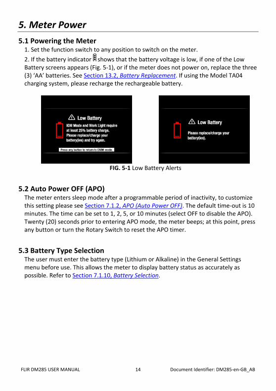
1. Set the function switch to any position to switch on the meter. 2. If the battery indicator shows that the battery voltage is low, if one of the Low Battery screens appears (Fig. 5-1), or if the meter does not power on, replace the three (3) ‘AA’ batteries. See Section 13.2, Battery Replacement. If using the Model TA04 charging system, please recharge the rechargeable battery.
FIG. 5-1 Low Battery Alerts
5.2 Auto Power OFF (APO) The meter enters sleep mode after a programmable period of inactivity, to customize this setting please see Section 7.1.2, APO (Auto Power OFF). The default time-out is 10 minutes. The time can be set to 1, 2, 5, or 10 minutes (select OFF to disable the APO). Twenty (20) seconds prior to entering APO mode, the meter beeps; at this point, press any button or turn the Rotary Switch to reset the APO timer.
5.3 Battery Type Selection The user must enter the battery type (Lithium or Alkaline) in the General Settings menu before use. This allows the meter to display battery status as accurately as possible. Refer to Section 7.1.10, Battery Selection.

FLIR DM285 USER MANUAL Document Identifier: DM285-en-GB_AB 15
6. Menu System 6.1 Using the Menu System
• Press OK to open the main menu, shown below:
Fig. 6-1 Main Menu
• Use the Navigation Pad left/right arrows to highlight an icon. From left to right the icons are Image Mode, Imager Settings, Gallery (for viewing thermal images and data logs), Advanced Menu, and General Settings.
• Press OK to open a menu or to set an option ON or OFF. When an option is ON a blue dot will appear next its icon. In some cases, use the navigation arrows to select an option.
• Use the Return button to exit menu levels and to return to the normal display mode.
• The mode of the meter dictates what icons are available for use.
6.2 Main Menu Options
6.2.1 Image Mode Menu This Image mode icon is only available in the thermal imaging mode. The Image mode has two options:
Image + DMM mode (default): Display will show DMM data on the thermal images while in the thermal imaging mode.
Image-only mode: Display shows thermal images only in the thermal imaging mode. Press OK on the Image mode icon to open the menu and use the arrow buttons to select the desired option.
6.2.2 Thermal Settings Menu Press OK at the Thermal Settings icon to access the following options: Color Palette, Emissivity, Laser pointer ON/OFF, and Cross hairs ON/OFF shown top to bottom in Fig. 6-2 below. Refer to Section 8.3, Thermal Settings Menu (Color Palette, Emissivity, Laser Pointer, and Crosshairs) for detailed information.
Fig. 6-2 Thermal Settings Menu

FLIR DM285 USER MANUAL Document Identifier: DM285-en-GB_AB 16
6.2.3 Gallery Mode In Gallery mode, view stored thermal images and logged readings. • Press OK at the Gallery icon. The display will show rows of stored thermal
images (100 max.)on the lower area of the display and data logs (up to 10 sets with 40,000 readings max.) on the upper area.
• Use the up/down arrows to step between image and reading log areas. • Use the left/right arrows to scroll through data logs or images. • Press OK to open a reading log or a thermal image. • Press OK again on a thermal image to bring up icons that will permit you to
delete the image, transmit the images via Bluetooth®, and to resize the image to full screen.
• Press OK again on a data log set to bring up icons that will permit you to delete the log or to transmit the log via Bluetooth®.
• For More detailed information, see Section 7.1.11, Delete all Datalogger Readings, Section 7.1.12, Delete all Stored Thermal Images, Section 8.5, Thermal Image Capture, and Section 10, Datalogger
6.2.4 Advanced Functions Menu Press OK at the Advanced Functions menu icon to access the functions listed below. Highlight a function using the arrow buttons and then press OK to activate it. Refer to the dedicated section for each as listed below for detailed information: • VFD (low pass filter), see Section 9.7, VFD (Low Pass Filter) • MAX-MIN-AVG Readings, see Section 9.8, MAX-MIN-AVG mode • (P) Peak mode, see Section 9.9, Peak mode • Relative mode, see Section 9.10, Relative mode • Datalogger, see Section 10, Datalogger
6.2.5 General Settings Menu 1. Press OK to open the main menu. 2. Press OK at the Settings icon to access the options. 3. See next section for detailed information on the General Settings mode.
FLIR DM285 USER MANUAL Document Identifier: DM285-en-GB_AB 17
7. General Settings 7.1 General Settings Navigation
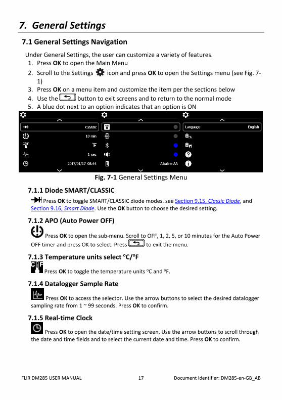
Under General Settings, the user can customize a variety of features. 1. Press OK to open the Main Menu 2. Scroll to the Settings icon and press OK to open the Settings menu (see Fig. 7-
1) 3. Press OK on a menu item and customize the item per the sections below 4. Use the button to exit screens and to return to the normal mode 5. A blue dot next to an option indicates that an option is ON
Fig. 7-1 General Settings Menu
7.1.1 Diode SMART/CLASSIC Press OK to toggle SMART/CLASSIC diode modes. see Section 9.15, Classic Diode, and
Section 9.16, Smart Diode. Use the OK button to choose the desired setting.
7.1.2 APO (Auto Power OFF)
Press OK to open the sub-menu. Scroll to OFF, 1, 2, 5, or 10 minutes for the Auto Power OFF timer and press OK to select. Press to exit the menu.
7.1.3 Temperature units select oC/oF
Press OK to toggle the temperature units oC and oF.
7.1.4 Datalogger Sample Rate
Press OK to access the selector. Use the arrow buttons to select the desired datalogger sampling rate from 1 ~ 99 seconds. Press OK to confirm.
7.1.5 Real-time Clock
Press OK to open the date/time setting screen. Use the arrow buttons to scroll through the date and time fields and to select the current date and time. Press OK to confirm.

FLIR DM285 USER MANUAL Document Identifier: DM285-en-GB_AB 18
7.1.6 Auto Hold / Data Hold
Auto hold: Use the OK button to toggle ON (blue dot) and OFF. For more information, see Section 9.5, Data Hold and Auto Hold.
7.1.7 Coarse Resolution Coarse Resolution (C.r. ON/OFF) allows the user to reduce the resolution to remove
distracting, quickly changing least significant digits. Use the OK button to toggle ON (blue dot) and OFF. This function is for Voltage function only. The range and resolution for the Voltage function will be adjusted as follows when Coarse Resolution is enabled:
o 600.0mV → 600mV o 6.000V → 6.00V o 60.00V → 60.0V o 600.0V → 600V o 1000V → 1000V o Default: OFF
7.1.8 Bluetooth® ON/OFF Press OK to toggle Bluetooth® ON/OFF (default is ON). See Section 11, Bluetooth®
7.1.9 Button-press tone ON/OFF Press OK to toggle the button-press tone ON/OFF
7.1.10 Battery type selection Press OK to select Alkaline or Lithium AA batteries in use.
7.1.11 Language selection Press OK to open the menu. Scroll to the desired language and press OK. Press to exit
7.1.12 Delete all Datalogger readings Press OK to delete all datalogger records. The meter will ask for confirmation.
7.1.13 Delete all Stored Thermal Images
Press OK to delete all saved thermal images. The meter will ask for confirmation.
7.1.14 View HELP Screen
Press OK to view FLIR support contact information.
7.1.15 Viewing meter component information
Press OK to view meter component firmware version information and Laser data: Meter firmware version
Lepton® camera interface firmware version Bluetooth® firmware version
Laser data

FLIR DM285 USER MANUAL Document Identifier: DM285-en-GB_AB 19
8. Thermal Imaging
8.1 Thermal Imager Basics In the Thermal Imaging mode, the user can measure a targeted surface’s temperature by detecting the energy emitted by the surface under test. Color variations reflect temperature variations. See Section 12.3, Infrared Energy and Thermal Imaging Overview for in-depth information. The laser pointer and display cross hairs assist in targeting. Press the IGM button to open the Thermal Imager. In Fig 8-1 the meter is set to color palette IRON. Select other palettes in the Thermal Settings Menu (refer to Section 8.3, Thermal Settings Menu).
Fig. 8-1 Thermal Image Example
1. IR Temperature measurement represents the temperature of the spot sensed.
Note that while the imager initializes, dashes will display. 2. MultiMeter Measurement 3. Cross hairs for targeting spots 4. Thermal image (120 x 160 pixels) 5. Main Menu (Press OK to open this menu) 6. Lowest reading measured in the current frame 7. Thermal scale shows the range of colors for the thermal image. The lighter the
color, the warmer the temperature; the darker the color, the cooler the temperature.
8. Highest reading measured in the current frame. 9. Status Icon Bar (see Section 4.4, Status Bar Display Icons for definitions)

FLIR DM285 USER MANUAL Document Identifier: DM285-en-GB_AB 20
8.2 Thermal Imager Operation To customize the Thermal Imager, refer to Section 8.3, Thermal Settings Menu. For basic operation, follow these steps: 1. Set the function switch to any position. 2. Press the IGM button to switch the Thermal Imager ON. Point the thermal
imaging lens (back of meter) toward an area to test. 3. The display will show the temperature in the upper left-hand corner of the
targeted area. 4. In the Thermal Imaging mode, use the laser pointer and display cross hairs for
targeting. These can be switched ON or OFF in the Thermal Settings Menu. 5. In the Thermal Imaging mode, the meter continues to operate normally as a
MultiMeter. In the Thermal Imaging mode, view electrical measurements and functions on the left side of the display. If desired, the meter can be set to image-only mode in the Image Mode menu, see Section 8.4, Image Mode Menu.
6. The Distance to Spot ratio for the imager is 30:1 meaning that the measurement spot is 30 times smaller than the distance from meter to spot (at 30”, the meter ‘sees’ a target spot of 1”). See Fig. 8-2.
7. The thermal imager’s resolution is 120 x 160 pixels and its FOV (Field of View) is 44 degrees (horizontal) by 57 degrees (vertical) see Fig. 8-3 (a) and (b).
Fig. 8-2 Distance-to-Spot ratio 30:1

FLIR DM285 USER MANUAL Document Identifier: DM285-en-GB_AB 21
Fig. 8-3 (a) Field of View – vertical Fig. 8-3 (b) Field of View - horizontal
8.3 Thermal Settings Menu (Color Palette, Emissivity, Laser Pointer, Crosshairs) 1. Press OK to open the main menu
2. Scroll to the Thermal Settings icon and press OK 3. Refer to the Thermal Settings screenshot and
details below
Fig. 8.4 Thermal Settings Menu
Icon Description Use
Color Palette Press OK to step through the display color palettes (Iron,
Rainbow, or Gray).
Emissivity Press OK and then use up/down arrows to scroll to a preset
(0.95, 0.85, 0.75, or 0.65) or to the fine-tuning icon Ԑ. To fine tune, press OK at the fine-tuning icon and use the arrow buttons to set the value, press OK to confirm. The range is 0.10 to 0.99 in 0.01 steps.
Laser pointer Press OK to toggle the laser pointer ON (blue circle) or OFF

FLIR DM285 USER MANUAL Document Identifier: DM285-en-GB_AB 22
Cross hairs Press OK to switch the cross hairs ON or OFF
8.4 Image Mode Menu
The Image Mode menu allows you to select:
Image + DMM mode where you can view DMM data superimposed on the thermal images or: Image-only mode where DMM measurements are removed from the thermal images
8.5 Thermal Image Capture Short press the Display Save button to store a displayed thermal image (or DMM screen) to the meter’s internal memory. Up to 100 images can be stored. Saved thermal images are fully radiometric (each pixel includes temperature measurement data). Note that the imager must be fully initialized (indicated by display of IR temperature measurement instead of dashes) before radiometric data can be captured. To view radiometric data within captured thermal images, copy the images to a PC and view using FLIR Tools. To view stored images:
1. Press OK to open the Main Menu 2. Press OK at the Gallery icon 3. Use the left/right arrow buttons to scroll through the images (note that the
datalogging records are located here also, on the upper display area) 4. Press OK to open a selected image 5. Press OK to open a menu permitting recycling of image, full-screen sizing,
and transmission of image via Bluetooth® 6. Use the RETURN button to exit screens and to return to the normal
operating mode
8.6 Thermal Image Freeze (Data Hold) In Data Hold mode, the displayed reading or thermal image is frozen. To enter/exit Data Hold mode, press the H (hold) button. In Hold mode, the indicator appears.
8.7 Using the Multimeter in the IGMTM mode The Multimeter can be used as described in Section 9, Multimeter Operation while the IGMTM mode is active. Multimeter readings, status bar icons, and operational modes such as PEAK, RELATIVE, and MIN-MAX-AVG can be viewed directly on top of the thermal image when IMAGE + DMM mode is selected in the Image Mode menu (see Section 6.2.1, Image Mode Menu).

FLIR DM285 USER MANUAL Document Identifier: DM285-en-GB_AB 23
9. MultiMeter Operation Caution: Before operating the device, you must read, understand, and follow all instructions, dangers, warnings, cautions, and notes. Caution: When the meter is not in use, the function switch should be set to the OFF position. Caution: When connecting the probe leads to the device under test, connect the COM (negative) lead before connecting the positive lead. When removing the probe leads, remove the positive lead before removing the COM (negative) lead.
9.1 Auto/Manual Range Mode In Auto range mode, the meter automatically selects the most appropriate measurement scale. In Manual range mode, the desired range (scale) can be adjusted by the user. Auto range mode is the default mode of operation. When a new function is selected with the function switch, the starting mode is Auto range and the indicator is displayed.
1. To enter Manual range mode, short press the button. To change the
range, press the button repeatedly until the desired range is displayed. 2. To return to the Auto range mode, long press the button until the Auto
Range indicator is again displayed.
9.2 Probe Connection Alert For voltage or current measurements (except µA), with the tests leads incorrectly connected to the meter (or not connected at all), one of the error displays shown below will appear:
9.3 Test Lead Holder Accessory If desired, connect the supplied Test Lead Holder to the rear of the meter. The Test Lead Holder connects to the back of the meter (to items 1 and 5 as shown in Fig. 4-2 in Section 4, Meter Description and Reference Guide).

FLIR DM285 USER MANUAL Document Identifier: DM285-en-GB_AB 24
9.4 Out of Range Warning (OL) If the input is over/under the full-scale range in Manual range mode, or if the signal has exceeded the maximum/minimum input in Auto range mode, ‘OL’ is displayed.
9.5 Data Hold and Auto Hold The meter has two HOLD modes: classic Data Hold and Auto Hold. To select Data Hold or Auto Hold as the default, please use the General Settings menu (see Section 6.2.5, General Settings Menu and Section 7, General Settings). Refer to the paragraphs below for instructions on using the Hold modes.
9.5.1 Data Hold Mode In Data Hold mode, the primary meter display freezes the last reading. To enter/exit Data
Hold mode, short press the (hold) button. In Hold mode, the indicator appears.
9.5.2 Auto Hold Mode In Auto hold mode, the secondary display freezes the last reading and the icon appears. The real-time reading appears on the primary display. The held reading will not change unless the difference between the held reading and any new reading is > 50 digits. The Auto hold function will capture a reading if the reading is > 1% full scale (trigger level) for Voltage, Current, and Capacitance. For Resistance, Diode, and Temperature the trigger is active as long as OL (over range).
To enter/exit Auto hold mode, short press the (hold) button.
FLIR DM285 USER MANUAL Document Identifier: DM285-en-GB_AB 25
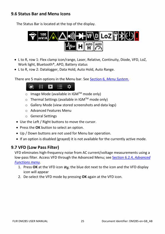
9.6 Status Bar and Menu Icons
The Status Bar is located at the top of the display.
• L to R, row 1: Flex clamp icon/range, Laser, Relative, Continuity, Diode, VFD, LoZ, Work light, Bluetooth®, APO, Battery status
• L to R, row 2: Datalogger, Data Hold, Auto Hold, Auto Range. There are 5 main options in the Menu bar. See Section 6, Menu System.
o Image Mode (available in IGMTM mode only) o Thermal Settings (available in IGMTM mode only) o Gallery Mode (view stored screenshots and data logs) o Advanced Features Menu o General Settings
• Use the Left / Right buttons to move the cursor. • Press the OK button to select an option. • Up / Down buttons are not used for Menu bar operation. • If an option is disabled (grayed) it is not available for the currently active mode.
9.7 VFD (Low Pass Filter) VFD eliminates high-frequency noise from AC current/voltage measurements using a low-pass filter. Access VFD through the Advanced Menu; see Section 6.2.4, Advanced Functions menu.
1. Press OK at the VFD icon ; the blue dot next to the icon and the VFD display icon will appear
2. De-select the VFD mode by pressing OK again at the VFD icon.

FLIR DM285 USER MANUAL Document Identifier: DM285-en-GB_AB 26
9.8 MAX-MIN-AVG mode Access MAX-MIN-AVG mode through the Advanced Menu; see Section 6.2.4, Advanced Functions menu. Press OK on this icon to begin recording and viewing the highest, lowest, and average readings.
1. A blue dot appears next to the icon when you select this mode. 2. The highest reading will be shown next to the MAX icon 3. The lowest reading will be shown next to the MIN icon 4. The average reading will be shown next to the AVG icon 5. Press OK at this icon in the Advanced Menu to exit this mode.
9.9 Peak Mode (AC Current and Voltage Measurements only) Access Peak mode (P) through the Advanced Menu; see Section 6.2.4, Advanced Functions menu. In Peak mode, the meter captures and displays the positive and negative ACA or ACV peak values. The Peak display values change only when higher/lower values are registered.
1. Press OK to show the Peak Max and Peak Min readings on the display. 2. Press OK to switch this mode OFF.
9.10 Relative mode Access Relative mode ( ) through the Advanced Menu; see Section 6.2.4, Advanced Functions menu. Press OK on this icon to capture a reference reading which to compare subsequent measurements.
1. A blue dot appears next to the icon when you select this mode. 2. The reference value will be displayed next to the Relative icon. 3. The primary display will show the difference between the measured value and
the stored reference. 4. Press OK at this icon to switch the Relative mode OFF.

FLIR DM285 USER MANUAL Document Identifier: DM285-en-GB_AB 27
9.11 Voltage and Frequency Measurements 1. Set the function switch to one of the following positions:
• (VDC) or (VAC) for high voltage measurements. • (milli-volts) for low voltage measurements (use MODE to select AC or DC).
• for voltage measurements using the meter’s low input impedance mode. The LoZ indicator will be displayed (use MODE to select AC or DC).
2. Insert the black probe lead into the negative COM terminal and the red probe lead into the positive terminal.
3. For mV and LoZ measurements use the button to select AC or DC measurement: • The indicator will be displayed for AC measurements. • The indicator will be displayed for DC measurements.
4. Connect the probe leads in parallel to the part under test. 5. Read the voltage value on the display. 6. The Frequency (Hz) of the measured voltage is shown on the smaller, secondary
display digits above the primary voltage reading. Press the button to view only the Frequency reading.
7. Refer to Section 6.2.4, Advanced Functions Menu, for details on VFD, MIN-MAX-AVG, Peak, and Relative modes of operation.
Fig. 9-1 Voltage and Frequency Measurements

FLIR DM285 USER MANUAL Document Identifier: DM285-en-GB_AB 28
9.12 Non-Contact Voltage Detector
1. Set the function switch to the NCV position. See Fig. 9-2. 2. Be sure to remove the test leads from the meter when doing NCV tests. 3. Use the button to choose High (80~1000V) or Low (160~1000V) Sensitivity
range (see the sensitivity icons in Fig. 9-2). 4. Position the top of the meter close to a source of voltage or electromagnetic field. 5. When the meter detects a voltage or electromagnetic field it emits a continuous
tone and the displayed NCV icon will turn red in color and blink.
Fig. 9-2 Non-Contact Voltage Detector
9.13 Resistance Measurements Warning: Do not perform diode, resistance or continuity tests before removing power from capacitors and other devices under test during a measurement. Injury to persons can occur.
1. Refer to Fig. 9-3. Set the function switch to the position. 2. Use to step to the Ω display if necessary. 3. Insert the black probe lead into the negative COM terminal and the red probe
lead into the positive Ω terminal. 4. Touch the tips of the probe across the circuit or component under test. 5. Read the resistance value on the display. 6. Refer to Section 6.2.4, Advanced Functions Menu, for details on MIN-MAX-AVG
and Relative modes of operation.
FLIR DM285 USER MANUAL Document Identifier: DM285-en-GB_AB 29
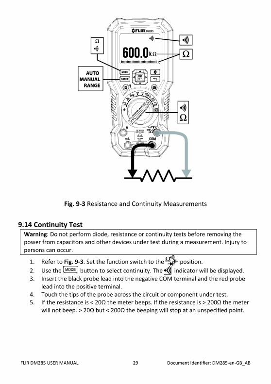
Fig. 9-3 Resistance and Continuity Measurements
9.14 Continuity Test Warning: Do not perform diode, resistance or continuity tests before removing the power from capacitors and other devices under test during a measurement. Injury to persons can occur.
1. Refer to Fig. 9-3. Set the function switch to the position. 2. Use the button to select continuity. The indicator will be displayed. 3. Insert the black probe lead into the negative COM terminal and the red probe
lead into the positive terminal. 4. Touch the tips of the probe across the circuit or component under test. 5. If the resistance is < 20Ω the meter beeps. If the resistance is > 200Ω the meter
will not beep. > 20Ω but < 200Ω the beeping will stop at an unspecified point.

FLIR DM285 USER MANUAL Document Identifier: DM285-en-GB_AB 30
9.15 Classic Diode Test Warning: Do not perform diode tests before removing the power to the diode or other devices under test during a measurement. Injury to persons can occur.
1. If not already selected, choose CLASSIC Diode test mode in the General Settings menu (see Section 6.2.5, General Settings Menu and Section 7, General Settings).
2. Set the function switch to the diode position. Use the MODE button to select the diode test function. The diode indicator will be displayed.
3. Insert the black probe lead into the negative COM terminal and the red probe lead into the positive terminal.
4. Touch the tips of the probe across the diode or semiconductor junction under test in one polarity (direction) and then in the opposite polarity as shown in Fig. 9-4.
5. If the reading is between 0.400 and 0.800V in one direction and OL (overload) in the opposite direction, the component is good. If the measurement is 0V in both directions (shorted) or OL in both directions (open), the component is bad.
Fig. 9-4 Classic Diode Test

FLIR DM285 USER MANUAL Document Identifier: DM285-en-GB_AB 31
9.16 Smart Diode Test Warning: Do not perform diode tests before removing the power from capacitors and other devices under test during a measurement. Injury to persons can occur.
1. If not already selected, choose SMART Diode test mode in the General Settings menu (see Section 6.2.5, General Settings Menu and Section 7, General Settings).
2. Set the function switch to the diode position. Use the MODE button to select the diode test function. The diode indicator will be displayed.
3. Insert the black probe lead into the negative COM terminal and the red probe lead into the positive Ω terminal.
4. Touch the tips of the probe across the diode or semiconductor junction under test.
5. If the reading is between ± 0.400 ~ 0.800V, the component is good; BAD or O.L displays indicate a defective component.
NOTES: In SMART Diode mode the meter checks diodes using an alternating test signal sent through the diode in both directions. This allows the user to check the diode without having to reverse polarity manually. The meter display will show ± 0.400 ~ 0.800V for a good diode, ‘BAD’ for a shorted diode, and ‘O.L’ for an opened diode. See Fig. 9-5 below:
Fig. 9-5 SMART Diode Test

FLIR DM285 USER MANUAL Document Identifier: DM285-en-GB_AB 32
9.17 Capacitance Measurements Warning: Do not perform capacitance tests before removing power to the capacitor or other devices under test during a measurement. Injury to persons can occur.
1. Set the function switch to the position. 2. Use the button to select the capacitance measurement. The F (Farad) unit
of measure will be displayed. 3. Insert the black probe lead into the negative COM terminal and the red probe
lead into the positive terminal. 4. Touch the tips of the probe across the part under test. 5. Read the capacitance value on the display. 6. Refer to Section 6.2.4, Advanced Functions Menu, for details on MIN-MAX-AVG
and Relative modes of operation. Note: For very large capacitance values, it may take several minutes for the measurement to settle and the final reading to stabilize.
Fig. 9-6 Capacitance Measurements

FLIR DM285 USER MANUAL Document Identifier: DM285-en-GB_AB 33
9.18 Type K Temperature Measurements 1. Set the function to the Temperature position. 2. Use the button to select temperature measurement. The °F or °C unit will
be displayed. To change from F to C or from C to F, please use the General Settings menu (see Section 6.2.5, General Settings Menu and Section 7, General Settings).
3. While observing the polarity, insert the thermocouple adapter into the negative COM terminal and the positive terminal.
4. Touch the tip of the thermocouple to the part under test. Keep the thermocouple tip on the part until the reading stabilizes.
5. Read the temperature value on the display. 6. To avoid electrical shock, disconnect the thermocouple adapter before turning
the function switch to another position.
Fig. 9-7 Temperature Measurements
9.19 Current and Frequency Measurements (A, mA, µA) For test lead current measurements, disconnect the part under test and connect the test leads in series with the part, see Fig. 9-8.
Fig. 9-8 Disconnected component

FLIR DM285 USER MANUAL Document Identifier: DM285-en-GB_AB 34
9.19.1 Test Lead Current Measurements (A, mA, and µA) 1. For test lead measurements (A, mA, and µA), set the function switch to the or
position. 2. Insert the black probe lead into the negative COM terminal and the red probe lead into
one of the following positive terminals: • A for high current measurements. • mA for lower current measurements. • µA for micro-amp measurements
3. Use the button to select AC or DC measurement. • The indicator will be displayed for AC measurements. • The indicator will be displayed for DC measurements.
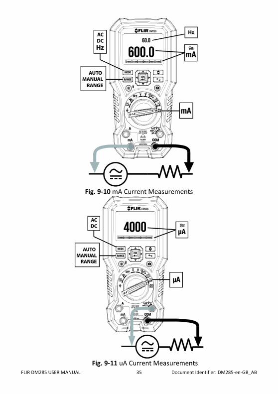
4. Connect the probe leads in series with the part in accordance with Fig. 9-8 and Fig. 9-9 for ‘A’ measurements, Fig. 9-10 for mA measurements, or Fig. 9-11 for µA measurements.
5. Read the current and frequency values on the display. Frequency (Hz) is available only in the A AC and mA AC modes. Use the to view the Frequency only.
6. Refer to Section 6.2.4, Advanced Functions Menu, for details on VFD, MIN-MAX-AVG, Peak, and Relative modes of operation.
Fig. 9-9 High Current ‘A’ Measurements
FLIR DM285 USER MANUAL Document Identifier: DM285-en-GB_AB 35
Fig. 9-10 mA Current Measurements
Fig. 9-11 uA Current Measurements

FLIR DM285 USER MANUAL Document Identifier: DM285-en-GB_AB 36
9.19.2 FLEX Clamp Adaptor Current and Frequency Measurements FLIR Flex Clamp Adaptors (Models TA72 and TA74, for example) and other clamp adaptors connect to the DM285 to display current measurements made by a clamp adaptor.
1. Turn the function dial to the position.
2. Connect a Clamp adaptor as shown in Fig. 9-12. 3. Set the Range of the Flex Clamp Adaptor to match the range of the DM285. 4. Use the RANGE button to select the range of the DM285 (1, 10, 100 mv/A). The
selected range appears on the upper left side of the DM285 display. 5. Operate the Flex Clamp per instructions provided with the Flex Clamp meter. 6. Read the current measured by the Flex Clamp on the DM285 LCD. The frequency also
appears on the DM285’s secondary display.
Fig. 9-12 FLEX Clamp Adaptor Application

FLIR DM285 USER MANUAL Document Identifier: DM285-en-GB_AB 37
10. Datalogger
Log up to 40,000 total readings over ten memory ‘sets’. Each time the datalogger is started a new memory set is opened and the previous one is archived.
10.1 Start Datalogging 1. Press OK to access the main menu 2. Press OK at the Advanced Menu icon 3. Press OK at the datalogger icon to begin storing readings at the sample rate
selected in the General Settings menu, see Section 7.1.4, Datalogger Sample Rate. The datalogger display icon will appear while the logger is running
10.2 Stop Datalogging 1. Press OK to access the main menu 2. Press OK at the Advanced Menu icon 3. Press OK at the datalogger icon to stop logging. The datalogger display icon
will switch off
10.3 View Datalogger Sets 1. Press OK to access the Main menu 2. Press OK at the Gallery icon 3. Use the up arrow to move the cursor up to the log area of the display (the lower
area is reserved for saved screenshot images). Scroll left/right to a data ‘set’ and press OK to open it. The list of recorded measurements for the set will appear.
10.4 Delete Datalogger Sets 1. With a datalog set open, press OK. Two icons will appear on the bottom of the
display, one for transmitting data and one for deleting. 2. Scroll to the Trash icon and press OK to delete all of the readings in the selected
set. 3. Delete data using the General Settings menu also, however using this method,
all readings are deleted, not individual sets. See Section 6.2.5, General Settings Menu and Section 7, General Settings.
10.5 Transmit Datalogger Sets via Bluetooth® Transmit data logs to a remote device running the FLIR Tools software suite. Refer to the next section (Bluetooth® Transmission) for more information. 1. With a datalog ‘set’ open, press OK. Two icons will appear on the bottom of the
display (one for transmitting and one for deleting). 2. Scroll to the transmission icon and press OK to begin transmitting all of the
readings in the selected set. 3. Note that a micro USB port is in the battery compartment. When connected to a
PC the DM285 operates in the same manner as an external storage medium where you can drag and drop data logs and images from the meter to a PC.

FLIR DM285 USER MANUAL Document Identifier: DM285-en-GB_AB 38
11. Bluetooth® Transmission
When connected to a remote device running the FLIR Tools software suite, the DM285 (using the METERLiNK® protocol) can: • Send readings for live display on the remote device • Send saved data log files to the remote device • Send saved screen images (thermal and DMM) to the remote device
When connected to a remote FLIR camera that supports Bluetooth® BLE (Bluetooth® Low Energy), the DM285 can: • Send meter readings for live display on the camera screen
Download the FLIR Tools software suite at the link below: http://www1.flir.com/l/5392/2011-06-08/IUUE
1. Any Bluetooth® BLE device running FLIR Tools can find and connect to the meter. 2. When successful communication between the meter and a remote device or FLIR
camera is established, the Bluetooth® icon appears on the meter display. 3. Open the Main menu (by pressing OK) and use the Gallery mode to locate the
stored images and data log sets. You can transmit Images and data log sets directly from the Gallery mode. For further information, refer to Section 6.2.3, Gallery mode. See additional information provided in Section 10, Datalogger.
4. Refer to the FLIR Tools help utility from within the software suite for detailed information and tutorials on using the FLIR Tools application.
Note: The Bluetooth® utility defaults to ON but can be disabled if desired in the General Settings menu (see Section 7, General Settings).

FLIR DM285 USER MANUAL Document Identifier: DM285-en-GB_AB 39
12. Appendices
12.1 Emissivity Factors for Common Materials
12.2 Non-Uniformity Correction
A non-uniformity correction (or NUC) is an image correction carried out by the camera software to compensate for different sensitivities of detector elements and other optical and geometrical disturbances1. The NUC is an automatic function that takes place periodically (approximately every 2-3 minutes) or whenever the inner core of the cameral detects a ±2oC temperature change.
1. Definition from the imminent international adoption of DIN 54190-3 (Non-destructive testing – Thermographic testing – Part 3: Terms and definitions).
Material Emissivity Material Emissivity
Asphalt 0.90 to 0.98 Cloth (black) 0.98
Concrete 0.94 Skin (human) 0.98
Cement 0.96 Leather 0.75 to 0.80
Sand 0.90 Charcoal (powder) 0.96
Soil 0.92 to 0.96 Lacquer 0.80 to 0.95
Water 0.92 to 0.96 Lacquer (matt) 0.97
Ice 0.96 to 0.98 Rubber (black) 0.94
Snow 0.83 Plastic 0.85 to 0.95
Glass 0.90 to 0.95 Timber 0.90
Ceramic 0.90 to 0.94 Paper 0.70 to 0.94
Marble 0.94 Chromium Oxides 0.81
Plaster 0.80 to 0.90 Copper Oxides 0.78
Mortar 0.89 to 0.91 Iron Oxides 0.78 to 0.82
Brick 0.93 to 0.96 Textiles 0.90

FLIR DM285 USER MANUAL Document Identifier: DM285-en-GB_AB 40
12.3 Infrared Energy and Thermal Imaging Overview A thermal imager generates an image based on temperature differences. In a thermal image, the hottest item in the scene appears as white and the coldest item as black. All other items are represented as a gray scale value between white and black. The DM285 also offers color images to simulate hot (lighter colors) and cold (darker colors) temperatures. It may take some time to get used to the thermal imagery. Having a basic understanding of the differences between thermal and daylight cameras can help with getting the best performance from the DM285. One difference between thermal and daylight cameras has to do with where the energy comes from to create an image. When viewing an image with an ordinary camera, there must be some source of visible light (something hot, such as the sun or other lighting) that reflects off the objects in the scene to the camera. The same is true with human eyesight; most what people see is based on reflected light energy. On the other hand, the thermal imager detects energy that is directly radiated from objects in the scene.
Therefore, hot objects such as parts on engines and exhaust pipes appear white, while the sky, puddles of water and other cold objects appear dark (or cool). Scenes with familiar objects will be easy to interpret with some experience. Infrared energy is part of a complete range of radiation called the electromagnetic spectrum. The electromagnetic spectrum includes gamma rays, X-rays, ultraviolet, visible, infrared, microwaves (RADAR), and radio waves. The only difference is their wavelength or frequency. All these forms of radiation travel at the speed of light. Infrared radiation lies between the visible and RADAR portions of the electromagnetic spectrum. The primary source of infrared radiation is heat or thermal radiation. Any object that has a temperature radiates in the infrared portion of the electromagnetic spectrum. Even objects that are very cold, such as an ice cube, emit infrared. When an object is not quite hot enough to radiate visible light, it will emit most of its energy in the infrared. For example, hot charcoal may not give off light, but it does emit infrared radiation, which we feel as heat. The warmer the object, the more infrared radiation it emits. Infrared imaging devices produce an image of invisible infrared or “heat” radiation that is unseen by the human eye. There are no colors or “shades” of gray in infrared, only varying intensities of radiated energy. The infrared imager converts this energy into an image that we can interpret.
The FLIR Infrared Training center offers training (including online training) and certification in all aspects of thermography: http://www.infraredtraining.com/.

FLIR DM285 USER MANUAL Document Identifier: DM285-en-GB_AB 41
13. Maintenance 13.1 Cleaning and Storage Wipe the housing with a damp cloth as needed. Use a high-quality lens wipe to remove dirt or smudges from the meter lenses and display window. Please do not use abrasives or solvents to clean the meter housing, lenses, or display window. If the meter is not to be used for an extended period, remove the batteries and store them separately.
13.2 Battery Replacement The Battery symbol flashes with no ‘bars’ when the batteries have reached a critical level. The meter displays readings within specifications while the low battery indicator is on. The meter powers off before it displays an out of tolerance reading. WARNING: To avoid electrical shock, disconnect the meter from any connected circuits, remove the test leads from the meter terminals, and set the function switch to the OFF position before attempting to replace the batteries.
1. Unscrew and remove the battery compartment cover. 2. Replace the four (4) standard AAA batteries, observing correct polarity. 3. If using the Model TA04 rechargeable lithium polymer battery system, please
recharge the rechargeable battery. 4. Secure the battery compartment cover.
Never dispose of used batteries or rechargeable batteries in household waste. As consumers, users are legally required to take used batteries to appropriate collection sites, the retail store where the batteries were purchased, or wherever batteries are sold.
13.3 Fuse Replacement The two fuses are accessed via the battery compartment. The fuses are rated:
• mA: 440 mA, 1000 V IR 10 kA fuse (Bussmann DMM-B-44/100). • A: 11 A, 1000 V IR 20 kA fuse (Bussmann DMM-B-11A). • Fuse kit PN: FS881, contains one of each fuse type.
13.4 Disposal of Electronic Waste As with most electronic products, this equipment must be disposed of in an environmentally friendly way, and in accordance with existing regulations for electronic waste. Please contact your FLIR Systems representative for more details.

FLIR DM285 USER MANUAL Document Identifier: DM285-en-GB_AB 42
14. Specifications 14.1 General specifications Maximum voltage: 1000 V DC or 1000 V AC RMS
Display Counts: 6000
Polarity Indication: Automatic, positive implied, negative indicated
Over-range Indication: OL
Measuring Rate: 3 samples per second
Power Requirements: 3 x 1.5 V AA alkaline/lithium batteries or optional Model TA04-KIT lithium polymer rechargeable battery system
Approximate battery life for thermal imager:
6 hours: Alkaline ‘AA’ Battery x 3
13 hours: Energizer L91 Lithium (Li/FeS2) ‘AA’ Battery x 3
13 hours: Optional Rechargeable Battery: Li-Polymer; FLIR PN: TA04-KIT
Auto Power Off: Default 10 minutes
Operating Temp/RH: -10°C to 30°C (14°F to 86°F), < 85% RH
30°C to 40°C (86°F to 104°F), < 75% RH
40°C to 50°C (104°F to 122°F), <45% RH
Storage Temperature/RH: -20°C to 60°C (-4°F to 140°F), 0-80% RH (without batteries)
Temperature Coefficient: 0.1 x (specified accuracy)/°C, < 18°C (64.4°F), >28°C (82.4°F)
Operating Altitude: 2000m (6560’)
Calibration Cycle: One year
Weight: 537g (18.9 oz.)
Dimensions: (L x W x H) 200 x 95 x 49mm (7.9 x 3.7 x 1.9 in.)
Safety: Complies with IEC 61010-1 CAT IV-600 V, CAT III-1000V
CAT Application Field
I Circuits not connected to mains.
II Circuits directly connected to a low-voltage installation.
III Building installation.
IV Source of the low-voltage installation.
EMC: EN 61326-1
Pollution degree: 2
Drop protection: 3m (9.8’)

FLIR DM285 USER MANUAL Document Identifier: DM285-en-GB_AB 43
14.2 Thermal Imaging Specifications IR Temperature Range -10 ~150°C (14 ~ 302°F) IR Temperature Resolution 0.1°C/F Image Sensitivity < or equal to 150mK (0.15°C) IR Temperature Accuracy 3°C or 3% whichever is greater (> 25°C [77°F]) or 5°C (-10 to 25°C
[14~77°F]) Emissivity 0.95 maximum (4 presets and a fine-tuning feature) Distance to Spot ratio 30:1 Response time 150ms Spectral Response 8~14um Scanning type Continuous Repeatability 0.5% Image Detector Lepton® Field of View (FOV) 120 x 160 pixels (44o x 57o) Color Palettes Iron, Rainbow, and Greyscale Stored thermal image radiometry Fully radiometric Laser type Class 1 Laser power < 0.4mW
14.3 Electrical Specifications Accuracy is given as ± (% of reading + counts of least significant digit) at 23°C ± 5°C, with relative humidity < 80% Temperature coefficient: 0.1 * (Specified accuracy) / °C, < 18°C, > 28°C AC Function notes:
ACV and ACA are ac coupled, true RMS. For all AC functions, LCD displays 0 counts when the reading < 10 counts. For square waves, accuracy is unspecified. For non-sinusoidal waveforms, additional accuracy for Crest Factor (C.F.):
Add 1.0% for C.F. 1.0 to 2.0 Add 2.5% for C.F. 2.0 to 2.5 Add 4.0% for C.F. 2.5 to 3.0
Max. Crest Factor of Input Signal: 3.0 @ 3000 counts 2.0 @ 4500 counts 1.5 @ 6000 counts
Frequency Response is specified for sine waveform.
DC Voltage
Range OL Reading Resolution Accuracy
6.000V 6.600V 0.001V
±(0.09% + 2D) 60.00V 66.00V 0.01V
600.0V 660.0V 0.1V
1000V 1100V 1V
Input Impedance: 10MΩ Overload Protection: AC/DC 1000V

FLIR DM285 USER MANUAL Document Identifier: DM285-en-GB_AB 44
AC Voltage
Range OL Reading Resolution Accuracy Freq. Response
6.000V 6.600V 0.001V ±(1.0% + 3D) 45Hz ~ 500Hz
60.00V 66.00V 0.01V
±(1.0% + 3D) 45Hz ~ 1kHz 600.0V 660.0V 0.1V
1000V 1100V 1V
Input Impedance: 10MΩ (< 100pF) Overload Protection: AC/DC 1000V
Lo-Z Voltage (Auto AC & DC Detection)
Range OL Reading Resolution Accuracy
600.0V DC & AC 660.0V 0.1V ±(2.0% + 3D)
1000V DC & AC 1100V 1V
Input Impedance: about 3kΩ Frequency Response: 45 ~ 1kHz (Sine Wave) Overload Protection: AC/DC 1000V
DC mV
Range OL Reading Resolution Accuracy
600.0mV 660.0mV 0.1mV ±(0.5% + 2D)
Input Impedance: 10MΩ Overload Protection: AC/DC 1000V
AC mV
Range OL Reading Resolution Accuracy
600.0mV 660.0mV 0.1mV ±(1.0% + 3D)
Frequency Response: 45 ~ 1kHz (Sine Wave) Input Impedance: 10MΩ Overload Protection: AC/DC 1000V
DC Current
Range OL Reading Resolution Accuracy
60.00mA 66.00mA 0.01mA ±(1.0% + 3D)
400.0mA 660.0mA 0.1mA
6.000A 6.600A 0.001A ±(1.0% + 3D)
FLIR DM285 USER MANUAL Document Identifier: DM285-en-GB_AB 45
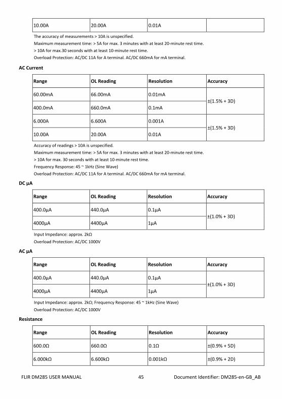
10.00A 20.00A 0.01A
The accuracy of measurements > 10A is unspecified. Maximum measurement time: > 5A for max. 3 minutes with at least 20-minute rest time. > 10A for max.30 seconds with at least 10-minute rest time. Overload Protection: AC/DC 11A for A terminal. AC/DC 660mA for mA terminal.
AC Current
Range OL Reading Resolution Accuracy
60.00mA 66.00mA 0.01mA ±(1.5% + 3D)
400.0mA 660.0mA 0.1mA
6.000A 6.600A 0.001A ±(1.5% + 3D)
10.00A 20.00A 0.01A
Accuracy of readings > 10A is unspecified. Maximum measurement time: > 5A for max. 3 minutes with at least 20-minute rest time. > 10A for max. 30 seconds with at least 10-minute rest time. Frequency Response: 45 ~ 1kHz (Sine Wave) Overload Protection: AC/DC 11A for A terminal. AC/DC 660mA for mA terminal.
DC μA
Range OL Reading Resolution Accuracy
400.0μA 440.0μA 0.1μA ±(1.0% + 3D)
4000μA 4400μA 1μA
Input Impedance: approx. 2kΩ Overload Protection: AC/DC 1000V
AC μA
Range OL Reading Resolution Accuracy
400.0μA 440.0μA 0.1μA ±(1.0% + 3D)
4000μA 4400μA 1μA
Input Impedance: approx. 2kΩ; Frequency Response: 45 ~ 1kHz (Sine Wave) Overload Protection: AC/DC 1000V
Resistance
Range OL Reading Resolution Accuracy
600.0Ω 660.0Ω 0.1Ω ±(0.9% + 5D)
6.000kΩ 6.600kΩ 0.001kΩ ±(0.9% + 2D)

FLIR DM285 USER MANUAL Document Identifier: DM285-en-GB_AB 46
60.00kΩ 66.00kΩ 0.00kΩ ±(0.9% + 2D)
600.0kΩ 660.0kΩ 0.1kΩ ±(0.9% + 2D)
6.000MΩ 6.600MΩ 0.001MΩ ±(0.9% + 2D)
50.00MΩ 55.00MΩ 0.01MΩ ±(3.0% + 5D)
Overload Protection: AC/DC 1000V
Continuity
Range OL Reading Resolution Accuracy
600.0Ω 660.0Ω 0.1Ω ±(0.9% + 5D)
Continuity: Built-in beeper sounds when measured resistance is less than 20Ω and is off when measured resistance is more than 200Ω. Between 20Ω and 200Ω the beeper will stop at an unspecified point. Continuity Indicator: 2KHz Tone Buzzer; Response Time of Buzzer: < 500μsec. Overload Protection: AC/DC 1000V
Diode
Range OL Reading Resolution Typical Reading
1.500V 1.550V 0.001V 0.400 ~ 0.800V
Open Circuit Voltage: Approx. 1.8V; Overload Protection: AC/DC 1000V
Frequency
Range OL Reading Resolution Accuracy
100.00Hz 100.00Hz 0.01Hz
±(0.1% + 2D) 1000.0Hz 1000.0Hz 0.1Hz
10.000kHz 10.000kHz 0.001kHz
100.00kHz 100.00kHz 0.01kHz
ACV - Minimum Sensitivity (including LoZ ACV):
Range 5Hz ~ 1kHz 1kHz ~ 10kHz >10kHz
600.0mV 60mV 100mV Unspecified
6.000V 0.6V 6V Unspecified
60.00V 6V 10V Unspecified
600.0V 60V 100V Unspecified
1000V 600V Unspecified Unspecified
FLIR DM285 USER MANUAL Document Identifier: DM285-en-GB_AB 47
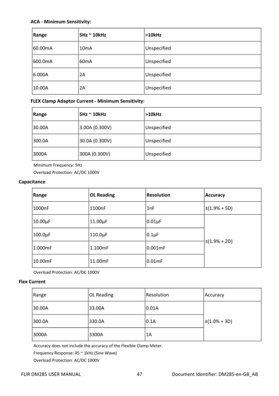
ACA - Minimum Sensitivity:
Range 5Hz ~ 10kHz >10kHz
60.00mA 10mA Unspecified
600.0mA 60mA Unspecified
6.000A 2A Unspecified
10.00A 2A Unspecified
FLEX Clamp Adaptor Current - Minimum Sensitivity:
Range 5Hz ~ 10kHz >10kHz
30.00A 3.00A (0.300V) Unspecified
300.0A 30.0A (0.300V) Unspecified
3000A 300A (0.300V) Unspecified
Minimum Frequency: 5Hz Overload Protection: AC/DC 1000V
Capacitance
Range OL Reading Resolution Accuracy
1000nF 1100nF 1nF ±(1.9% + 5D)
10.00µF 11.00µF 0.01µF
±(1.9% + 2D) 100.0µF 110.0µF 0.1µF
1.000mF 1.100mF 0.001mF
10.00mF 11.00mF 0.01mF
Overload Protection: AC/DC 1000V
Flex Current
Range OL Reading Resolution Accuracy
30.00A 33.00A 0.01A
±(1.0% + 3D) 300.0A 330.0A 0.1A
3000A 3300A 1A
Accuracy does not include the accuracy of the Flexible Clamp Meter. Frequency Response: 45 ~ 1kHz (Sine Wave) Overload Protection: AC/DC 1000V

FLIR DM285 USER MANUAL Document Identifier: DM285-en-GB_AB 48
Type-K Temperature
Range OL Reading Resolution Accuracy (DMM) Accuracy (IGM)
-40.0°C to 400.0°C ≤ -44.0°C, ≥ 440.0°C 0.1°C ± (1% + 3°C) ± (1% + 5°C)
-40.0°F to 752.0°F ≤ -44.0°F, ≥ 824.0°F 0.1°F ± (1% + 5.4°F) ± (1% + 9°F)
The accuracy applies with a 30-minute warmup time and is unspecified when the Work Light is ON. Accuracy does not include the accuracy of the thermocouple probe. Accuracy specification assumes surrounding temperature stable to ±1 °C. For surrounding temperature changes of ± 2 °C, rated accuracy applies after 2 hours. Overload Protection: AC/DC 1000V.
NCV (Non-Contact Voltage Detector)
Voltage Range (High Sensitivity): 80V to 1000V
Voltage Range (Low Sensitivity): 160V to 1000V
Peak Max and Peak Min Hold
For ACV, AC mV, ACA, ACmA, AC μA, and Flex Current modes (unavailable for LoZ mode)
Specified accuracy ± 150 digits for < 6000 counts
Specified accuracy ± 250 digits for >/= 6000 counts
VFD (Low Pass Filter)
For ACV, AC mV, ACA, ACmA, AC μA, and Flex Current modes (unavailable for LoZ mode)
Specified accuracy is for 45Hz ~ 65Hz
Specified accuracy ± 4% for 65Hz ~ 400Hz
Accuracy is unspecified for > 400Hz
Cut-off Frequency: 800Hz (± 100Hz)
Work Light
Color Temperature: 4000-5000°K
Beam Angle: ± 20°
Light Output: 70 lumens, minimum
Power: 0.5 Watt RMS
15. Technical Support
Technical Support Website https://support.flir.com
16. Warranty 16.1 Limited 10-year Warranty This product is protected by FLIR’s Limited 10-Year Warranty. Visit https://support.flir.com/prodreg to read the Limited 10-Year Warranty document.

FLIR DM285 USER MANUAL Document Identifier: DM285-en-GB_AB 49
Corporate Headquarters FLIR Systems, Inc. 27700 SW Parkway Avenue Wilsonville, OR 97070 USA Customer Support Technical Support Website https://support.flir.com Publication Identification No.: DM285-en-GB Release Version: AB Release Date: March 2020 Language: en-GB