Embed Size (px)
Citation preview
FLIR Systems Object Model version 1.21
©Real Time Automation, Inc. 09/15/2009 Page 1 of 74
FLIR Systems
EtherNet/IP and Modbus TCP Object Models
Object Model revision: 1.21
Real Time Automation, Inc. 150 S. Sunnyslope Rd. Suite 130 Brookfield, WI 53005 262.439.4999 (V) 262.439.4989 (F) www.rtaautomation.com
2014, FLIR Systems Publ. No.: T559874, rev. 1.21
FLIR Systems Object Model version 1.21
©Real Time Automation, Inc. 09/15/2009 Page 2 of 74
Chapter 1 Introduction to EtherNet/IP
Ethernet/IP™ (EIP) is a high-level industrial application layer protocol for industrial automation applications. Built on the standard TCP/IP protocol suite, EIP uses all the traditional Ethernet hardware and software to define an application layer protocol that structures the task of configuring, accessing and controlling industrial automation devices. Ethernet/IP classifies Ethernet nodes as predefined device types with specific behaviors. The set of device types and the EIP application layer protocol is based on the Control and Information Protocol (CIP) layer used in both Devicenet™ and Controlnet™. Building on these widely used protocol suites, Ethernet/IP for the first time provides a seamless integrated system from the sensor-actuator network to the controller and enterprise networks. EIP provides a wide-ranging, comprehensive, certifiable standard suitable to a wide variety of automation devices.
Ethernet/IP uses the tools and technologies of traditional Ethernet Ethernet/IP uses all the transport and control protocols used in traditional Ethernet, including the Transport Control Protocol (TCP), the Internet Protocol (IP), and the media access and signaling technologies found in off-the-shelf Ethernet interface cards. Building on these standard PC technologies means that EIP works transparently with all the standard off-the-shelf Ethernet devices found in today’s marketplace. It also means that EIP can be easily supported on standard PCs and all their derivatives. Even more importantly, basing EIP on a standard technology platform ensures that EIP will move forward as the base technologies evolve.
Ethernet/IP is a certifiable standard EtherNet/IP ensures a comprehensive, consistent standard by careful, multi-vendor attention to the specification and through certified test labs as is used for other well-known communication standards like DeviceNet and ControlNet. The EtherNet/IP Certification program ensures the consistency and quality of field devices.
EIP is built on a widely accepted protocol layer EIP is constructed from a very widely implemented standard used in DeviceNet and ControlNet called the Control and Information Protocol (CIP). This standard organizes networked devices as a collection of objects. It defines the access, object behavior and extensions which allow widely disparate devices to be accessed using a common mechanism. Over 500 vendors now support the CIP protocol in present day products. Using this technology in EIP means that EIP is based on a widely understood, widely implemented standard that does not require a new technology shakedown period.
2014, FLIR Systems Publ. No.: T559874, rev. 1.21

FLIR Systems Object Model version 1.21
©Real Time Automation, Inc. 09/15/2009 Page 3 of 74
CIP – The Core of EtherNet/IP The Communications and Information Protocol (CIP) is a communications protocol for transferring automation data between two devices. In the CIP Protocol, every network device represents itself as a series of objects. Each object is simply a grouping of the related data values in a device. For example, every CIP device is required to make an Identity object available to the network. The identity object contains related identity data values called attributes. Attributes for the identity object include the vendor ID, date of manufacture, device serial number, and other identity data. CIP does not specify at all how this object data is implemented, only what data values or attributes must be supported and that these attributes must be available to other CIP devices.
The Identity object is an example of a required object. There are three types of objects defined by the CIP protocol; Required Object, Application Objects and Vendor Specific Objects. The collection of specific object for a particular device is known as the device’s Object Model.
REQUIRED OBJECTS Required objects are required by the specification to be included in every CIP device. These objects include the Identity object, a Message Router object and a Network object.
The identity object contains related identity data values called attributes. Attributes for the identity object include the vendor ID, date of manufacturer, device serial number, and other identity data.
The Message Router object is an object which routes explicit request messages from object to object in a device.
A Network object contains the physical connection data for the object. For a CIP device on DeviceNet, the network object contains the MacID and other data describing the interface to the CAN network. For EIP devices, the network object contains the IP address and other data describing the interface to the Ethernet port on the device.
APPLICATION OBJECTS Application objects are the objects that define the data encapsulated by the device. These objects are specific to the device type and function. For example, a Motor object on a Drive System has attributes describing the frequency, current rating and motor size. An Analog Input object on an I/O device has attributes that define the type, resolution and current value for the analog input.
These application layer objects are predefined for a large number of common device types. All CIP devices with the same device type (Drive Systems, Motion Control, Valve Transducer…etc) must contain the identical series of application objects. The series of application objects for a particular device type is known as the device profile. A large number of profiles for many device types have been defined. Supporting a device profile allows a user to easily understand and switch from a vendor of one device type to another vendor with that same device type.
A device vendor can also group Application Layer Objects into assembly objects. These super objects contain attributes of one or more Application Layer Objects. Assembly objects form a convenient package for transporting data between devices. For example, a vendor of a
2014, FLIR Systems Publ. No.: T559874, rev. 1.21
FLIR Systems Object Model version 1.21
©Real Time Automation, Inc. 09/15/2009 Page 4 of 74
Temperature Controller with multiple temperature loops may define assemblies for each of the temperature loops and an assembly with data from all temperature loops. The user can then pick the assembly that is most suited for the application and how often to access each assembly. For example, one temperature assembly may be configured to report every time it changes state while the second may be configured to report every one-second regardless of a change in state.
Assemblies are usually predefined by the vendor, but CIP also defines a mechanism in which the user can dynamically create an assembly from application layer object attributes.
VENDOR SPECIFIC OBJECTS Objects not found in the profile for a device class are termed Vendor Specific. The vendor includes these objects as additional features of the device. The CIP protocol provides access to these vendor extension objects in exactly the same method as either application or required objects. This data is strictly of the vendor’s choosing and is organized in whatever method makes sense to the device vendor.
In addition to specifying how device data is represented to the network, the CIP protocol specifies a number of different ways in which that data can be accessed such as cyclic, polled and change-of-state.
ADVANTAGES TO EIP The advantages of the CIP protocol layer over EtherNet/IP are numerous. The consistent device access means that a single configuration tool can configure CIP devices on different networks from a single access point without using vendor specific software. The classification of all devices as objects decreases the training and startup required when new devices are brought online. EIP provides improved response time and greater data throughput than DeviceNet and ControlNet. EIP links devices from the sensor bus level to the control level to the enterprise level with a consistent application layer interface.
PLC COMMUNICATION OVER ETHERNET/IP Two types of devices communicate over EtherNet/IP. One type, Adapters, are the devices that move I/O between the physical world and the EtherNet/IP network. Adapter devices are “end” devices in a network. Valves, Drives, I/O Devices and Cameras are typically Adapter devices. The Flir camera is an Adapter device. The other device is a Scanners device. Scanners open connections and send outputs to one or more Adapter devices. A Programmable Controller is a typically a Scanner device in an EtherNet/IP network.
Scanner devices send outputs to one or more Adapter devices. Adapter devices send inputs to a Scanner. The Output Assembly Instances defined later in this document defines the outputs sent from the Scanner device to the FLIR Camera. The Input Assembly Instance defined later in this document defines the inputs sent from the Camera to the Scanner device.
2014, FLIR Systems Publ. No.: T559874, rev. 1.21
FLIR Systems Object Model version 1.21
©Real Time Automation, Inc. 09/15/2009 Page 5 of 74
EtherNet/IP Electronic Data Sheets Files Electronic Data Sheets (EDS) are simply ASCII files that describe how a device can be used on an EtherNet/IP network. It describes the objects, attributes and services available in the device.
At the minimum, an EDS file conveys the identity information required for a network tool to recognize the device. For EtherNet/IP Scanners, the EDS File conveys information on the EtherNet/IP Adapters I/O messages. It details the specifics of the Input Message produced by the EtherNet/IP Adapter and the Output message consumed by the Adapter.
The amount of information stored in an EDS file varies from device to device. Some manufacturers store the minimum amount of information in the EDS file while other devices store all the details of every object and attribute in the device.
EDS files are sometimes shipped with a device in some media format like a CD or made available on the device manufacturers website. Some devices with extended data storage contain the EDS file internally within the device.
EDS File Structure
File Section – Administers the EDS file. Sometimes the URL keyword provides a link to a website where the latest version of the EDS can be found.
Device Section – Provides keying information that matches the EDS to a particular revision of a device. The first three attributes of the Identity Object (Object #1) are used by network tools to verify that this EDS file (Vendor, Model,…etc) plus the device revision matches the information found in the device. The network tool will not connect to a device unless all four Identity Object Parameters match. Some people mistakenly believe that the Minor Revision number is included in this match but that is not true.
Device Classification Section – Classifies the EDS for an EtherNet/IP network. The Device Classification Section is required for all EtherNet/IP devices.
Connection Manager Section – Identifies the CIP connections that are available in the device. This section indicates to the EtherNet/IP Scanner the Triggers and Transports available in the device. If a device supports multiple connections then every connection must be detailed in this section. Only connections that are specified in this section can be used in an EDS-based configuration tool.
Assembly, Params and ParamClass section – These sections are filled in as needed. For values that are limited to a limited to a defined set of values, Enumeration can be used to specify those values. Value ranges can be specified here also for Configurable parameters.
Capacity Section – This section indicates the number of connections available in the device and the connection speeds
Port Section – This section describes the Ethernet port. It is only applicable to devices that perform CIP routing. It is unnecessary for devices containing a single CIP port.
2014, FLIR Systems Publ. No.: T559874, rev. 1.21
FLIR Systems Object Model version 1.21
©Real Time Automation, Inc. 09/15/2009 Page 6 of 74
EtherNet/IP Add-on Profiles The RSLogix5000 Programming Tool from Rockwell Automation uses EtherNet/IP EDS files to understand the Object Model of an EtherNet/IP device. The EDS file describes what data is contained in the messages received from the EtherNet/IP device and what data it should send to the EtherNet/IP device. The addition of an EDS file to the standard RSLogix5000 device library is called an Add-on Profile by Rockwell Automation.
EDS files can be loaded into the RSLogix5000 programming tool in one of two ways. EDS files from vendors which are not highly integrated with Rockwell Automation are loaded manually. EDS files from vendors which are highly integrated with Rockwell Automation, like Flir, are automatically loaded and available with the more recent versions of RSLogix5000.
2014, FLIR Systems Publ. No.: T559874, rev. 1.21
FLIR Systems Object Model version 1.21
©Real Time Automation, Inc. 09/15/2009 Page 7 of 74
Chapter 2 EtherNet/IP Object Model
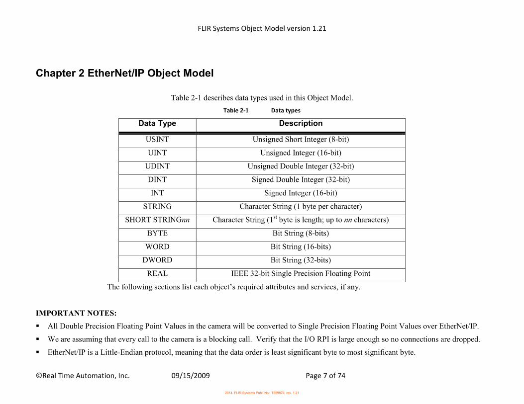
Table 2-1 describes data types used in this Object Model.
Table 2-1 Data types
Data Type Description
USINT Unsigned Short Integer (8-bit)
UINT Unsigned Integer (16-bit)
UDINT Unsigned Double Integer (32-bit)
DINT Signed Double Integer (32-bit)
INT Signed Integer (16-bit)
STRING Character String (1 byte per character)
SHORT STRINGnn Character String (1st byte is length; up to nn characters)
BYTE Bit String (8-bits)
WORD Bit String (16-bits)
DWORD Bit String (32-bits)
REAL IEEE 32-bit Single Precision Floating Point
The following sections list each object’s required attributes and services, if any.
IMPORTANT NOTES:
All Double Precision Floating Point Values in the camera will be converted to Single Precision Floating Point Values over EtherNet/IP.
We are assuming that every call to the camera is a blocking call. Verify that the I/O RPI is large enough so no connections are dropped.
EtherNet/IP is a Little-Endian protocol, meaning that the data order is least significant byte to most significant byte.
2014, FLIR Systems Publ. No.: T559874, rev. 1.21
FLIR Systems Object Model version 1.21
©Real Time Automation, Inc. 09/15/2009 Page 8 of 74
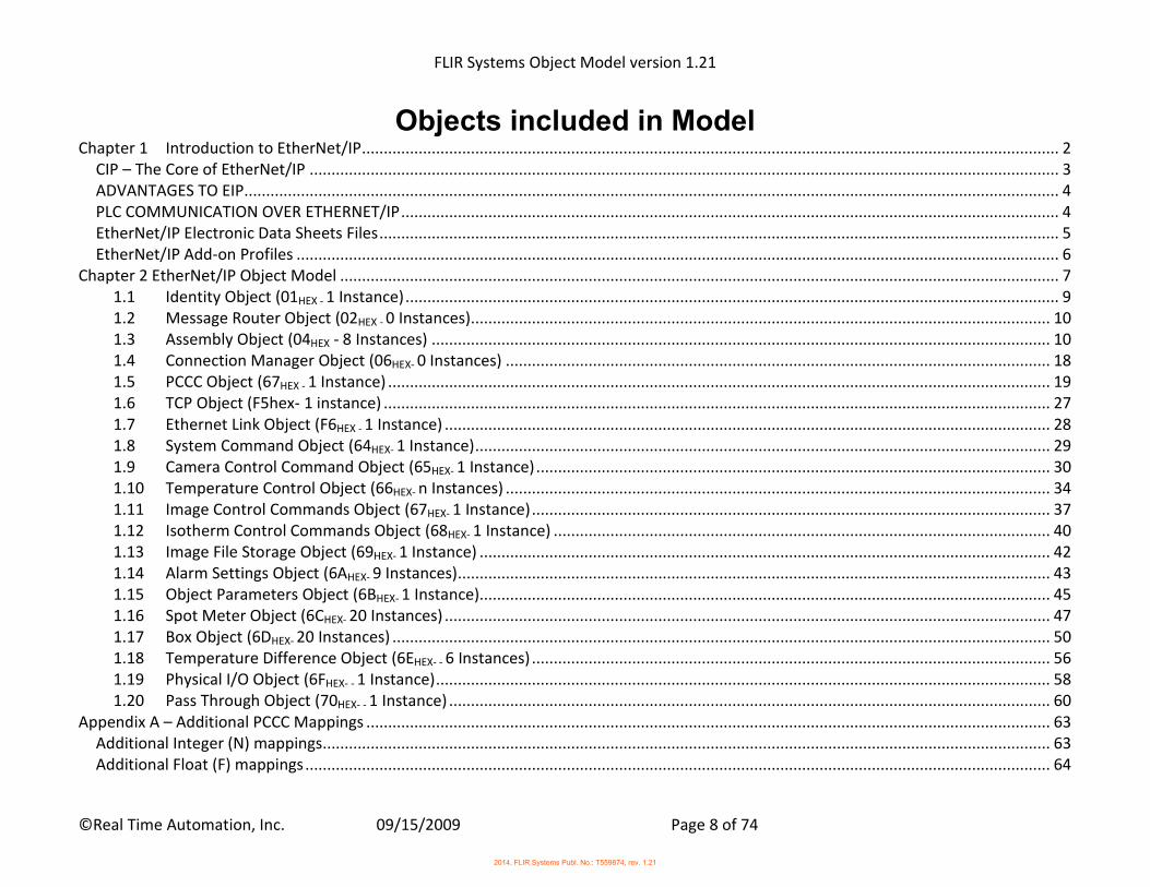
Objects included in Model Chapter 1 Introduction to EtherNet/IP ................................................................................................................................................................ 2
CIP – The Core of EtherNet/IP ............................................................................................................................................................................ 3
ADVANTAGES TO EIP ........................................................................................................................................................................................... 4
PLC COMMUNICATION OVER ETHERNET/IP ....................................................................................................................................................... 4
EtherNet/IP Electronic Data Sheets Files ............................................................................................................................................................ 5
EtherNet/IP Add-on Profiles ............................................................................................................................................................................... 6
Chapter 2 EtherNet/IP Object Model ..................................................................................................................................................................... 7
1.1 Identity Object (01HEX - 1 Instance) ...................................................................................................................................................... 9
1.2 Message Router Object (02HEX - 0 Instances) ..................................................................................................................................... 10
1.3 Assembly Object (04HEX - 8 Instances) .............................................................................................................................................. 10
1.4 Connection Manager Object (06HEX- 0 Instances) ............................................................................................................................. 18
1.5 PCCC Object (67HEX - 1 Instance) ........................................................................................................................................................ 19
1.6 TCP Object (F5hex- 1 instance) ......................................................................................................................................................... 27
1.7 Ethernet Link Object (F6HEX - 1 Instance) ........................................................................................................................................... 28
1.8 System Command Object (64HEX- 1 Instance) .................................................................................................................................... 29
1.9 Camera Control Command Object (65HEX- 1 Instance) ...................................................................................................................... 30
1.10 Temperature Control Object (66HEX- n Instances) ............................................................................................................................. 34
1.11 Image Control Commands Object (67HEX- 1 Instance) ....................................................................................................................... 37
1.12 Isotherm Control Commands Object (68HEX- 1 Instance) .................................................................................................................. 40
1.13 Image File Storage Object (69HEX- 1 Instance) ................................................................................................................................... 42
1.14 Alarm Settings Object (6AHEX- 9 Instances) ........................................................................................................................................ 43
1.15 Object Parameters Object (6BHEX- 1 Instance) ................................................................................................................................... 45
1.16 Spot Meter Object (6CHEX- 20 Instances) ........................................................................................................................................... 47
1.17 Box Object (6DHEX- 20 Instances) ....................................................................................................................................................... 50
1.18 Temperature Difference Object (6EHEX- - 6 Instances) ....................................................................................................................... 56
1.19 Physical I/O Object (6FHEX- - 1 Instance) ............................................................................................................................................. 58
1.20 Pass Through Object (70HEX- - 1 Instance) .......................................................................................................................................... 60
Appendix A – Additional PCCC Mappings ............................................................................................................................................................. 63
Additional Integer (N) mappings ....................................................................................................................................................................... 63
Additional Float (F) mappings ........................................................................................................................................................................... 64
2014, FLIR Systems Publ. No.: T559874, rev. 1.21
FLIR Systems Object Model version 1.21
©Real Time Automation, Inc. 09/15/2009 Page 9 of 74
Appendix B – Modbus TCP Assembly Mappings................................................................................................................................................... 65
Mapping 1 - Write Assembly Mapping ............................................................................................................................................................. 65
Mapping 2 - Read Assembly Values .................................................................................................................................................................. 66
Mapping 3 - Read Assembly Values .................................................................................................................................................................. 69
Appendix C – Additional Modbus TCP Mappings ................................................................................................................................................. 72
Additional Modbus mappings ........................................................................................................................................................................... 72
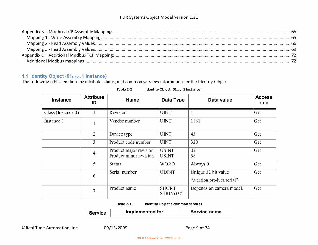
1.1 Identity Object (01HEX - 1 Instance) The following tables contain the attribute, status, and common services information for the Identity Object.
Table 2-2 Identity Object (01HEX - 1 Instance)
Instance Attribute
ID Name Data Type Data value
Access rule
Class (Instance 0) 1 Revision UINT 1 Get
Instance 1 1
Vendor number UINT 1161 Get
2 Device type UINT 43 Get
3 Product code number UINT 320 Get
4
Product major revision Product minor revision
USINT USINT
02 38
Get
5 Status WORD Always 0 Get
6
Serial number UDINT Unique 32 bit value
“.version.product.serial”
Get
7
Product name SHORT STRING32
Depends on camera model. Get
Table 2-3 Identity Object’s common services
Service Implemented for Service name
2014, FLIR Systems Publ. No.: T559874, rev. 1.21
FLIR Systems Object Model version 1.21
©Real Time Automation, Inc. 09/15/2009 Page 10 of 74
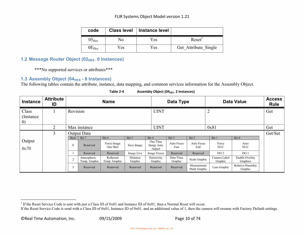
code Class level Instance level
05Hex No Yes Reset1
0EHex Yes Yes Get_Attribute_Single
1.2 Message Router Object (02HEX - 0 Instances)
***No supported services or attributes***
1.3 Assembly Object (04HEX - 8 Instances) The following tables contain the attribute, instance, data mapping, and common services information for the Assembly Object.
Table 2-4 Assembly Object (04HEX - 2 Instances)
Instance Attribute
ID Name Data Type Data Value
Access Rule
Class (Instance 0)
1 Revision UINT 2 Get
2 Max instance UINT 0x81 Get
Output
0x70
3 Output Data Byte Bit 7 Bit 6 Bit 5 Bit 4 Bit 3 Bit 2 Bit 1 Bit 0
0 Reserved Force Image
One Shot Save Image
One Time Image Auto
Adjust
Auto Focus Fast
Auto Focus Full
Force NUC
Auto NUC
1 Reserved Reserved Image Live Image Freeze Reserved Reserved DO 2 DO 1
2 Atmospheric Temp. Graphic
Reflected Temp. Graphic
Distance Graphic
Emissivity Graphic
Date/Time Graphic
Scale Graphic Camera Label
Graphic Enable Overlay
Graphics
3 Reserved Reserved Reserved Reserved Reserved Measurement Mark Graphic
Lens Graphic Relative Humidity
Graphic
Get/Set
1 If the Reset Service Code is sent with just a Class ID of 0x01 and Instance ID of 0x01, then a Normal Reset will occur. If the Reset Service Code is send with a Class ID of 0x01, Instance ID of 0x01, and an additional value of 1, then the camera will resume with Factory Default settings.
2014, FLIR Systems Publ. No.: T559874, rev. 1.21
FLIR Systems Object Model version 1.21
©Real Time Automation, Inc. 09/15/2009 Page 11 of 74
Instance Attribute
ID Name Data Type Data Value
Access Rule
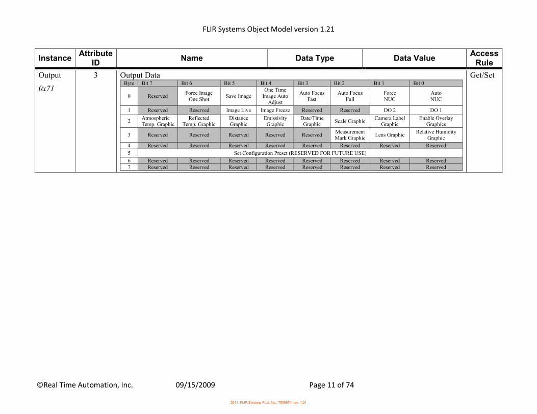
Output
0x71
3 Output Data Byte Bit 7 Bit 6 Bit 5 Bit 4 Bit 3 Bit 2 Bit 1 Bit 0
0 Reserved Force Image
One Shot Save Image
One Time Image Auto
Adjust
Auto Focus Fast
Auto Focus Full
Force NUC
Auto NUC
1 Reserved Reserved Image Live Image Freeze Reserved Reserved DO 2 DO 1
2 Atmospheric Temp. Graphic
Reflected Temp. Graphic
Distance Graphic
Emissivity Graphic
Date/Time Graphic
Scale Graphic Camera Label
Graphic Enable Overlay
Graphics
3 Reserved Reserved Reserved Reserved Reserved Measurement Mark Graphic
Lens Graphic Relative Humidity
Graphic
4 Reserved Reserved Reserved Reserved Reserved Reserved Reserved Reserved
5 Set Configuration Preset (RESERVED FOR FUTURE USE)
6 Reserved Reserved Reserved Reserved Reserved Reserved Reserved Reserved 7 Reserved Reserved Reserved Reserved Reserved Reserved Reserved Reserved
Get/Set
2014, FLIR Systems Publ. No.: T559874, rev. 1.21

FLIR Systems Object Model version 1.21
©Real Time Automation, Inc. 09/15/2009 Page 12 of 74
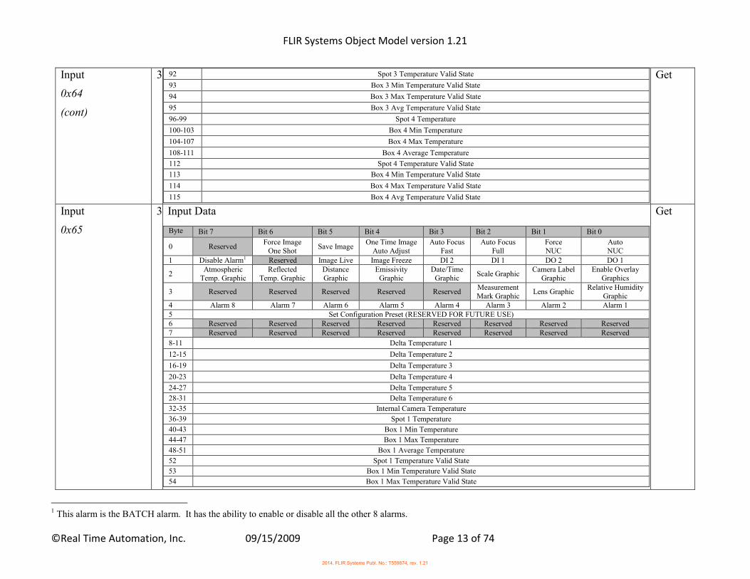
Input
0x64
3 Input Data
Byte Bit 7 Bit 6 Bit 5 Bit 4 Bit 3 Bit 2 Bit 1 Bit 0
0 Reserved Force Image
One Shot Save
Image One Time Image
Auto Adjust Auto Focus
Fast Auto Focus
Full Force NUC
Auto NUC
1 Disable Alarms1 Reserved Image Live
Image Freeze DI 2 DI 1 DO 2 DO 1
2 Atmospheric
Temp. Graphic Reflected
Temp. Graphic Distance Graphic
Emissivity Graphic
Date/Time Graphic
Scale Graphic Camera Label
Graphic Enable Overlay
Graphics
3 Reserved Reserved Reserved Reserved Reserved Measurement Mark Graphic
Lens Graphic Relative Humidity
Graphic 4 Alarm 8 Alarm 7 Alarm 6 Alarm 5 Alarm 4 Alarm 3 Alarm 2 Alarm 1 5 Set Configuration Preset (RESERVED FOR FUTURE USE) 6 Reserved Reserved Reserved Reserved Reserved Reserved Reserved Reserved 7 Reserved Reserved Reserved Reserved Reserved Reserved Reserved Reserved
8-11 Delta Temperature 1
12-15 Delta Temperature 2
16-19 Delta Temperature 3
20-23 Delta Temperature 4
24-27 Delta Temperature 5
28-31 Delta Temperature 6
32-35 Internal Camera Temperature
36-39 Spot 1 Temperature
40-43 Box 1 Min Temperature
44-47 Box 1 Max Temperature
48-51 Box 1 Average Temperature
52 Spot 1 Temperature Valid State
53 Box 1 Min Temperature Valid State
54 Box 1 Max Temperature Valid State
55 Box 1 Avg Temperature Valid State
56-59 Spot 2 Temperature
60-63 Box 2 Min Temperature
64-67 Box 2 Max Temperature
68-71 Box 2 Average Temperature
72 Spot 2 Temperature Valid State
73 Box 2 Min Temperature Valid State
74 Box 2 Max Temperature Valid State
75 Box 2 Avg Temperature Valid State
76-79 Spot 3 Temperature
80-83 Box 3 Min Temperature
84-87 Box 3 Max Temperature
88-91 Box 3 Average Temperature
Get
1 This alarm is the BATCH alarm. It has the ability to enable or disable all the other 8 alarms.
2014, FLIR Systems Publ. No.: T559874, rev. 1.21
FLIR Systems Object Model version 1.21
©Real Time Automation, Inc. 09/15/2009 Page 13 of 74
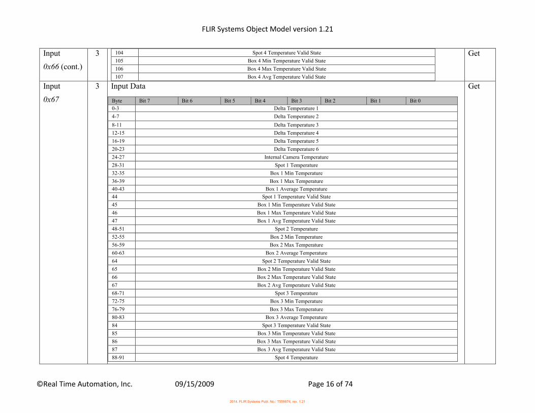
Input
0x64
(cont)
3
92 Spot 3 Temperature Valid State
93 Box 3 Min Temperature Valid State
94 Box 3 Max Temperature Valid State
95 Box 3 Avg Temperature Valid State
96-99 Spot 4 Temperature
100-103 Box 4 Min Temperature
104-107 Box 4 Max Temperature
108-111 Box 4 Average Temperature
112 Spot 4 Temperature Valid State
113 Box 4 Min Temperature Valid State
114 Box 4 Max Temperature Valid State
115 Box 4 Avg Temperature Valid State
Get
Input
0x65
3 Input Data
Byte Bit 7 Bit 6 Bit 5 Bit 4 Bit 3 Bit 2 Bit 1 Bit 0
0 Reserved Force Image
One Shot Save Image
One Time Image Auto Adjust
Auto Focus Fast
Auto Focus Full
Force NUC
Auto NUC
1 Disable Alarm1 Reserved Image Live Image Freeze DI 2 DI 1 DO 2 DO 1
2 Atmospheric
Temp. Graphic Reflected
Temp. Graphic Distance Graphic
Emissivity Graphic
Date/Time Graphic
Scale Graphic Camera Label
Graphic Enable Overlay
Graphics
3 Reserved Reserved Reserved Reserved Reserved Measurement Mark Graphic
Lens Graphic Relative Humidity
Graphic 4 Alarm 8 Alarm 7 Alarm 6 Alarm 5 Alarm 4 Alarm 3 Alarm 2 Alarm 1 5 Set Configuration Preset (RESERVED FOR FUTURE USE) 6 Reserved Reserved Reserved Reserved Reserved Reserved Reserved Reserved 7 Reserved Reserved Reserved Reserved Reserved Reserved Reserved Reserved
8-11 Delta Temperature 1
12-15 Delta Temperature 2
16-19 Delta Temperature 3
20-23 Delta Temperature 4
24-27 Delta Temperature 5
28-31 Delta Temperature 6
32-35 Internal Camera Temperature
36-39 Spot 1 Temperature
40-43 Box 1 Min Temperature
44-47 Box 1 Max Temperature
48-51 Box 1 Average Temperature
52 Spot 1 Temperature Valid State
53 Box 1 Min Temperature Valid State
54 Box 1 Max Temperature Valid State
Get
1 This alarm is the BATCH alarm. It has the ability to enable or disable all the other 8 alarms.
2014, FLIR Systems Publ. No.: T559874, rev. 1.21
FLIR Systems Object Model version 1.21
©Real Time Automation, Inc. 09/15/2009 Page 14 of 74
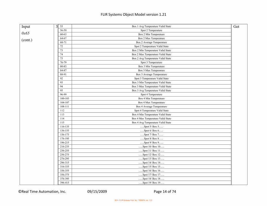
Input
0x65
(cont.)
3
55 Box 1 Avg Temperature Valid State
56-59 Spot 2 Temperature
60-63 Box 2 Min Temperature
64-67 Box 2 Max Temperature
68-71 Box 2 Average Temperature
72 Spot 2 Temperature Valid State
73 Box 2 Min Temperature Valid State
74 Box 2 Max Temperature Valid State
75 Box 2 Avg Temperature Valid State
76-79 Spot 3 Temperature
80-83 Box 3 Min Temperature
84-87 Box 3 Max Temperature
88-91 Box 3 Average Temperature
92 Spot 3 Temperature Valid State
93 Box 3 Min Temperature Valid State
94 Box 3 Max Temperature Valid State
95 Box 3 Avg Temperature Valid State
96-99 Spot 4 Temperature
100-103 Box 4 Min Temperature
104-107 Box 4 Max Temperature
108-111 Box 4 Average Temperature
112 Spot 4 Temperature Valid State
113 Box 4 Min Temperature Valid State
114 Box 4 Max Temperature Valid State
115 Box 4 Avg Temperature Valid State
116-135 …..Spot 5/ Box 5…..
136-155 …..Spot 6/ Box 6…..
156-175 …..Spot 7/ Box 7…..
176-195 …..Spot 8/ Box 8…..
196-215 …..Spot 9/ Box 9…..
216-235 …..Spot 10/ Box 10…..
236-255 …..Spot 11/ Box 11…..
256-275 …..Spot 12/ Box 12…..
276-295 …..Spot 13/ Box 13…..
296-315 …..Spot 14/ Box 14…..
316-335 …..Spot 15/ Box 15…..
336-355 …..Spot 16/ Box 16…..
356-375 …..Spot 17/ Box 17…..
376-395 …..Spot 18/ Box 18…..
396-415 …..Spot 19/ Box 19…..
Get
2014, FLIR Systems Publ. No.: T559874, rev. 1.21
FLIR Systems Object Model version 1.21
©Real Time Automation, Inc. 09/15/2009 Page 15 of 74
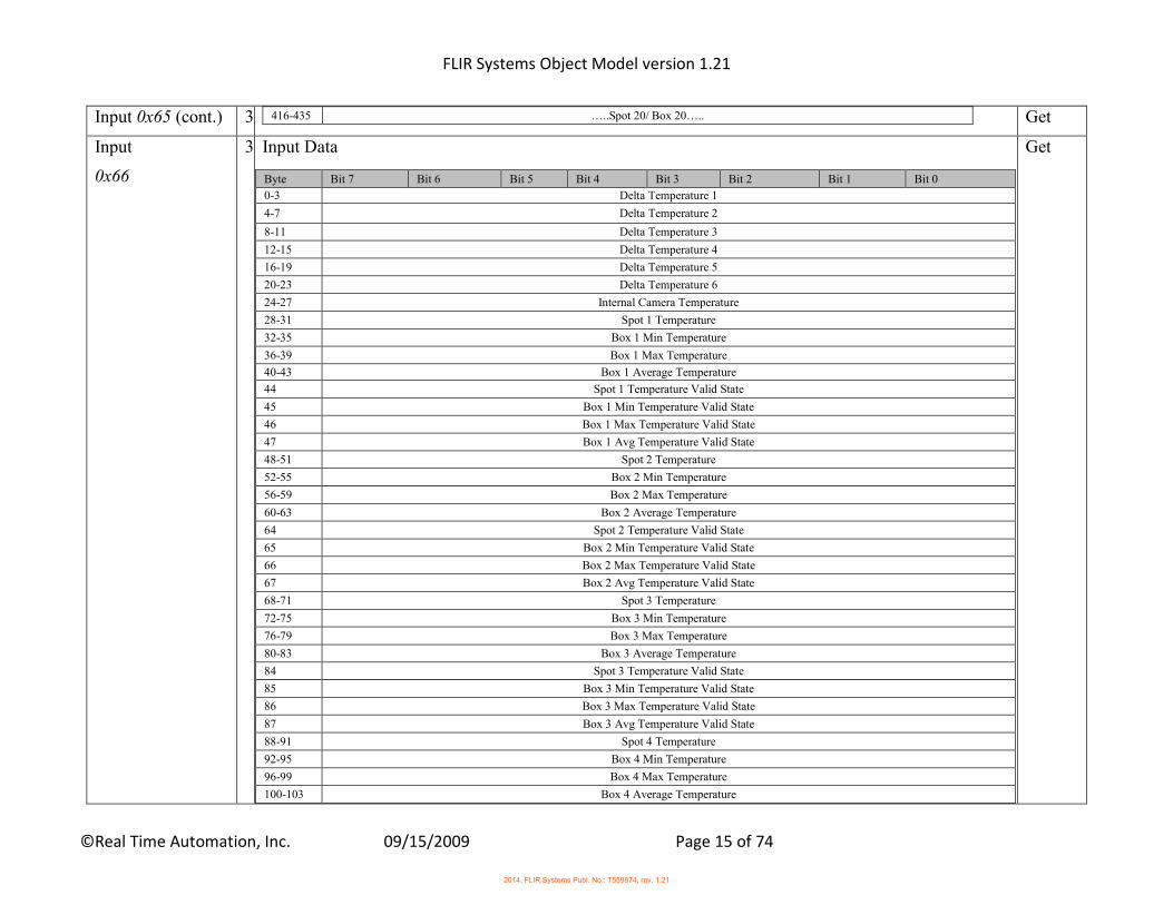
Input 0x65 (cont.) 3
416-435 …..Spot 20/ Box 20….. Get
Input
0x66
3 Input Data
Byte Bit 7 Bit 6 Bit 5 Bit 4 Bit 3 Bit 2 Bit 1 Bit 0
0-3 Delta Temperature 1
4-7 Delta Temperature 2
8-11 Delta Temperature 3
12-15 Delta Temperature 4
16-19 Delta Temperature 5
20-23 Delta Temperature 6
24-27 Internal Camera Temperature
28-31 Spot 1 Temperature
32-35 Box 1 Min Temperature
36-39 Box 1 Max Temperature
40-43 Box 1 Average Temperature
44 Spot 1 Temperature Valid State
45 Box 1 Min Temperature Valid State
46 Box 1 Max Temperature Valid State
47 Box 1 Avg Temperature Valid State
48-51 Spot 2 Temperature
52-55 Box 2 Min Temperature
56-59 Box 2 Max Temperature
60-63 Box 2 Average Temperature
64 Spot 2 Temperature Valid State
65 Box 2 Min Temperature Valid State
66 Box 2 Max Temperature Valid State
67 Box 2 Avg Temperature Valid State
68-71 Spot 3 Temperature
72-75 Box 3 Min Temperature
76-79 Box 3 Max Temperature
80-83 Box 3 Average Temperature
84 Spot 3 Temperature Valid State
85 Box 3 Min Temperature Valid State
86 Box 3 Max Temperature Valid State
87 Box 3 Avg Temperature Valid State
88-91 Spot 4 Temperature
92-95 Box 4 Min Temperature
96-99 Box 4 Max Temperature
100-103 Box 4 Average Temperature
Get
2014, FLIR Systems Publ. No.: T559874, rev. 1.21
FLIR Systems Object Model version 1.21
©Real Time Automation, Inc. 09/15/2009 Page 16 of 74
Input
0x66 (cont.)
3
104 Spot 4 Temperature Valid State
105 Box 4 Min Temperature Valid State
106 Box 4 Max Temperature Valid State
107 Box 4 Avg Temperature Valid State
Get
Input
0x67
3 Input Data
Byte Bit 7 Bit 6 Bit 5 Bit 4 Bit 3 Bit 2 Bit 1 Bit 0
0-3 Delta Temperature 1
4-7 Delta Temperature 2
8-11 Delta Temperature 3
12-15 Delta Temperature 4
16-19 Delta Temperature 5
20-23 Delta Temperature 6
24-27 Internal Camera Temperature
28-31 Spot 1 Temperature
32-35 Box 1 Min Temperature
36-39 Box 1 Max Temperature
40-43 Box 1 Average Temperature
44 Spot 1 Temperature Valid State
45 Box 1 Min Temperature Valid State
46 Box 1 Max Temperature Valid State
47 Box 1 Avg Temperature Valid State
48-51 Spot 2 Temperature
52-55 Box 2 Min Temperature
56-59 Box 2 Max Temperature
60-63 Box 2 Average Temperature
64 Spot 2 Temperature Valid State
65 Box 2 Min Temperature Valid State
66 Box 2 Max Temperature Valid State
67 Box 2 Avg Temperature Valid State
68-71 Spot 3 Temperature
72-75 Box 3 Min Temperature
76-79 Box 3 Max Temperature
80-83 Box 3 Average Temperature
84 Spot 3 Temperature Valid State
85 Box 3 Min Temperature Valid State
86 Box 3 Max Temperature Valid State
87 Box 3 Avg Temperature Valid State
88-91 Spot 4 Temperature
Get
2014, FLIR Systems Publ. No.: T559874, rev. 1.21
FLIR Systems Object Model version 1.21
©Real Time Automation, Inc. 09/15/2009 Page 17 of 74
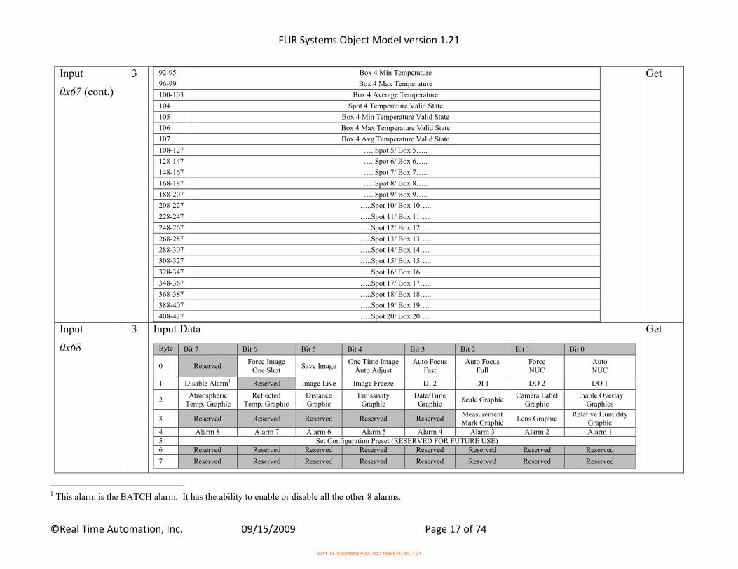
Input
0x67 (cont.)
3
92-95 Box 4 Min Temperature
96-99 Box 4 Max Temperature
100-103 Box 4 Average Temperature
104 Spot 4 Temperature Valid State
105 Box 4 Min Temperature Valid State
106 Box 4 Max Temperature Valid State
107 Box 4 Avg Temperature Valid State
108-127 …..Spot 5/ Box 5…..
128-147 …..Spot 6/ Box 6…..
148-167 …..Spot 7/ Box 7…..
168-187 …..Spot 8/ Box 8…..
188-207 …..Spot 9/ Box 9…..
208-227 …..Spot 10/ Box 10…..
228-247 …..Spot 11/ Box 11…..
248-267 …..Spot 12/ Box 12…..
268-287 …..Spot 13/ Box 13…..
288-307 …..Spot 14/ Box 14…..
308-327 …..Spot 15/ Box 15…..
328-347 …..Spot 16/ Box 16…..
348-367 …..Spot 17/ Box 17…..
368-387 …..Spot 18/ Box 18…..
388-407 …..Spot 19/ Box 19…..
408-427 …..Spot 20/ Box 20…..
Get
Input
0x68
3 Input Data
Byte Bit 7 Bit 6 Bit 5 Bit 4 Bit 3 Bit 2 Bit 1 Bit 0
0 Reserved Force Image
One Shot Save Image
One Time Image Auto Adjust
Auto Focus Fast
Auto Focus Full
Force NUC
Auto NUC
1 Disable Alarm1 Reserved Image Live Image Freeze DI 2 DI 1 DO 2 DO 1
2 Atmospheric
Temp. Graphic Reflected
Temp. Graphic Distance Graphic
Emissivity Graphic
Date/Time Graphic
Scale Graphic Camera Label
Graphic Enable Overlay
Graphics
3 Reserved Reserved Reserved Reserved Reserved Measurement Mark Graphic
Lens Graphic Relative Humidity
Graphic 4 Alarm 8 Alarm 7 Alarm 6 Alarm 5 Alarm 4 Alarm 3 Alarm 2 Alarm 1 5 Set Configuration Preset (RESERVED FOR FUTURE USE) 6 Reserved Reserved Reserved Reserved Reserved Reserved Reserved Reserved
7 Reserved Reserved Reserved Reserved Reserved Reserved Reserved Reserved
Get
1 This alarm is the BATCH alarm. It has the ability to enable or disable all the other 8 alarms.
2014, FLIR Systems Publ. No.: T559874, rev. 1.21
FLIR Systems Object Model version 1.21
©Real Time Automation, Inc. 09/15/2009 Page 18 of 74
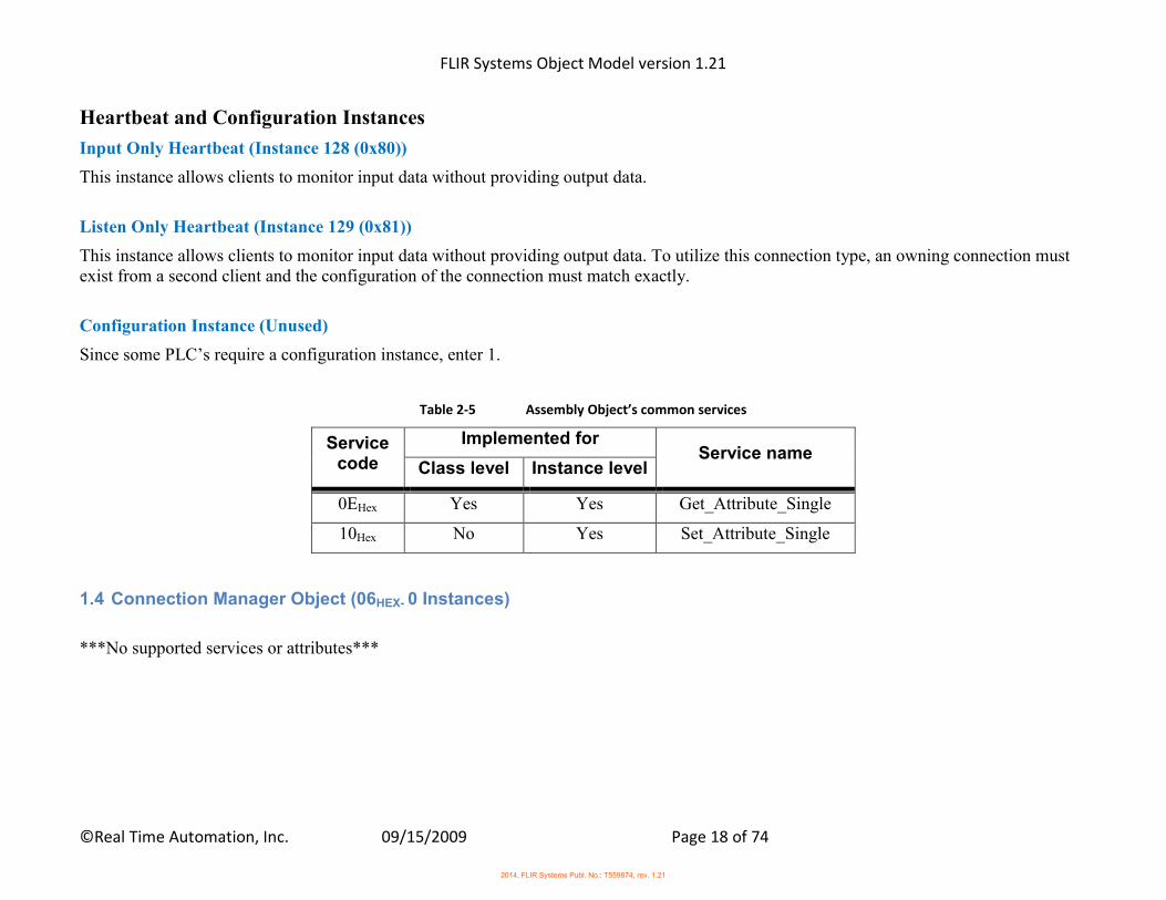
Heartbeat and Configuration Instances
Input Only Heartbeat (Instance 128 (0x80))
This instance allows clients to monitor input data without providing output data.
Listen Only Heartbeat (Instance 129 (0x81))
This instance allows clients to monitor input data without providing output data. To utilize this connection type, an owning connection must exist from a second client and the configuration of the connection must match exactly.
Configuration Instance (Unused)
Since some PLC’s require a configuration instance, enter 1.
Table 2-5 Assembly Object’s common services
Service code
Implemented for Service name
Class level Instance level
0EHex Yes Yes Get_Attribute_Single
10Hex No Yes Set_Attribute_Single
1.4 Connection Manager Object (06HEX- 0 Instances)
***No supported services or attributes***
2014, FLIR Systems Publ. No.: T559874, rev. 1.21

FLIR Systems Object Model version 1.21
©Real Time Automation, Inc. 09/15/2009 Page 19 of 74
1.5 PCCC Object (67HEX - 1 Instance) The PCCC Object has no class or instance attributes. The following tables contain common services information and PCCC Mapping parameters for the PCCC Object.
Table 1-6 PCCC Object’s common services
Service code
Implemented for Service name
Class level Instance level
4BHex* No Yes Execute PCCC Request
* EtherNet/IP devices use the “Execute PCCC Request” service code (4BHex) to communicate with older controllers like the PLC5E and the SLC 5/05.
Table 1-7 PCCC Object (67HEX) Output Integers– Read/Write
PCCC Register
Data Description
N10:0
Bit 7 Bit 6 Bit 5 Bit 4 Bit 3 Bit 2 Bit 1 Bit 0
Reserved Force Image One
Shot Save Image
One Time Image Auto Adjust
Auto Focus Fast
Auto Focus Full
Force NUC
Auto NUC
Bit 15 Bit 14 Bit 13 Bit 12 Bit 11 Bit 10 Bit 9 Bit 8
Reserved Reserved Image Live Image Freeze Reserved Reserved DO 2 DO 1
Output Integers
(Read/Write)
N10:1
Bit 7 Bit 6 Bit 5 Bit 4 Bit 3 Bit 2 Bit 1 Bit 0
Atmospheric Temp. Graphic
Reflected Temp. Graphic
Distance Graphic
Emissivity Graphic
Date/Time Graphic
Scale Graphic Camera Label
Graphic Enable Overlay
Graphics
Bit 15 Bit 14 Bit 13 Bit 12 Bit 11 Bit 10 Bit 9 Bit 8
Reserved Reserved Reserved Reserved Reserved Measurement Mark Graphic
Lens Graphic Relative Humidity
Graphic
N10:2 Bit 7 Bit 6 Bit 5 Bit 4 Bit 3 Bit 2 Bit 1 Bit 0 Reserved Reserved Reserved Reserved Reserved Reserved Reserved Reserved
Bit 15 Bit 14 Bit 13 Bit 12 Bit 11 Bit 10 Bit 9 Bit 8 Set Configuration Preset (RESERVED FOR FUTURE USE)
N10:3 Bit 7 Bit 6 Bit 5 Bit 4 Bit 3 Bit 2 Bit 1 Bit 0
Reserved Reserved Reserved Reserved Reserved Reserved Reserved Reserved
Bit 15 Bit 14 Bit 13 Bit 12 Bit 11 Bit 10 Bit 9 Bit 8 Reserved Reserved Reserved Reserved Reserved Reserved Reserved Reserved
2014, FLIR Systems Publ. No.: T559874, rev. 1.21
FLIR Systems Object Model version 1.21
©Real Time Automation, Inc. 09/15/2009 Page 20 of 74
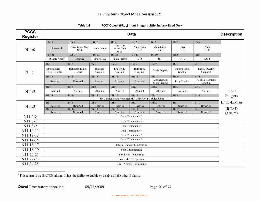
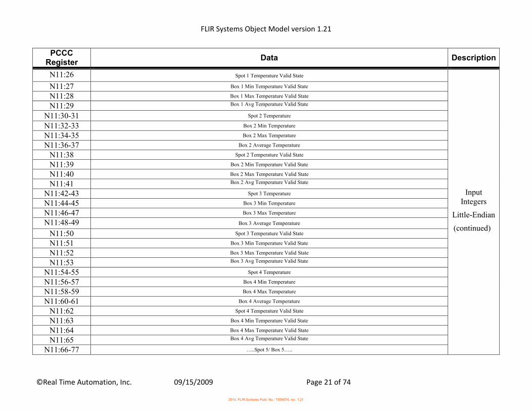
Table 1-8 PCCC Object (67HEX) Input Integers Little Endian– Read Only
PCCC Register
Data Description
N11:0
Bit 7 Bit 6 Bit 5 Bit 4 Bit 3 Bit 2 Bit 1 Bit 0
Reserved Force Image One
Shot Save Image
One Time Image Auto
Adjust
Auto Focus Fast
Auto Focus Full
Force NUC
Auto NUC
Bit 15 Bit 14 Bit 13 Bit 12 Bit 11 Bit 10 Bit 9 Bit 8
Disable Alarm1 Reserved Image Live Image Freeze DI 2 DI 1 DO 2 DO 1
Input Integers
Little-Endian
(READ ONLY)
N11:1
Bit 7 Bit 6 Bit 5 Bit 4 Bit 3 Bit 2 Bit 1 Bit 0
Atmospheric Temp. Graphic
Reflected Temp. Graphic
Distance Graphic
Emissivity Graphic
Date/Time Graphic
Scale Graphic Camera Label
Graphic Enable Overlay
Graphics
Bit 15 Bit 14 Bit 13 Bit 12 Bit 11 Bit 10 Bit 9 Bit 8
Reserved Reserved Reserved Reserved Reserved Measurement Mark Graphic
Lens Graphic Relative Humidity
Graphic
N11:2
Bit 7 Bit 6 Bit 5 Bit 4 Bit 3 Bit 2 Bit 1 Bit 0
Alarm 8 Alarm 7 Alarm 6 Alarm 5 Alarm 4 Alarm 3 Alarm 2 Alarm 1
Bit 15 Bit 14 Bit 13 Bit 12 Bit 11 Bit 10 Bit 9 Bit 8 Set Configuration Preset (RESERVED FOR FUTURE USE)
N11:3
Bit 7 Bit 6 Bit 5 Bit 4 Bit 3 Bit 2 Bit 1 Bit 0 Reserved Reserved Reserved Reserved Reserved Reserved Reserved Reserved
Bit 15 Bit 14 Bit 13 Bit 12 Bit 11 Bit 10 Bit 9 Bit 8 Reserved Reserved Reserved Reserved Reserved Reserved Reserved Reserved
N11:4-5 Delta Temperature 1
N11:6-7 Delta Temperature 2
N11:8-9 Delta Temperature 3
N11:10-11 Delta Temperature 4
N11:12-13 Delta Temperature 5
N11:14-15 Delta Temperature 6
N11:16-17 Internal Camera Temperature
N11:18-19 Spot 1 Temperature
N11:20-21 Box 1 Min Temperature
N11:22-23 Box 1 Max Temperature
N11:24-25 Box 1 Average Temperature
1 This alarm is the BATCH alarm. It has the ability to enable or disable all the other 8 alarms.
2014, FLIR Systems Publ. No.: T559874, rev. 1.21
FLIR Systems Object Model version 1.21
©Real Time Automation, Inc. 09/15/2009 Page 21 of 74
PCCC Register
Data Description
N11:26 Spot 1 Temperature Valid State
Input Integers
Little-Endian
(continued)
N11:27 Box 1 Min Temperature Valid State
N11:28 Box 1 Max Temperature Valid State
N11:29 Box 1 Avg Temperature Valid State
N11:30-31 Spot 2 Temperature
N11:32-33 Box 2 Min Temperature
N11:34-35 Box 2 Max Temperature
N11:36-37 Box 2 Average Temperature
N11:38 Spot 2 Temperature Valid State
N11:39 Box 2 Min Temperature Valid State
N11:40 Box 2 Max Temperature Valid State
N11:41 Box 2 Avg Temperature Valid State
N11:42-43 Spot 3 Temperature
N11:44-45 Box 3 Min Temperature
N11:46-47 Box 3 Max Temperature
N11:48-49 Box 3 Average Temperature
N11:50 Spot 3 Temperature Valid State
N11:51 Box 3 Min Temperature Valid State
N11:52 Box 3 Max Temperature Valid State
N11:53 Box 3 Avg Temperature Valid State
N11:54-55 Spot 4 Temperature
N11:56-57 Box 4 Min Temperature
N11:58-59 Box 4 Max Temperature
N11:60-61 Box 4 Average Temperature
N11:62 Spot 4 Temperature Valid State
N11:63 Box 4 Min Temperature Valid State
N11:64 Box 4 Max Temperature Valid State
N11:65 Box 4 Avg Temperature Valid State
N11:66-77 …..Spot 5/ Box 5…..
2014, FLIR Systems Publ. No.: T559874, rev. 1.21

FLIR Systems Object Model version 1.21
©Real Time Automation, Inc. 09/15/2009 Page 22 of 74
PCCC Register
Data Description
N11:78-89 …..Spot 6/ Box 6…..
Input
Integers
Little-Endian
(continued)
N11:90-101 …..Spot 7/ Box 7…..
N11:102-113 …..Spot 8/ Box 8…..
N11:114-125 …..Spot 9/ Box 9…..
N11:126-137 …..Spot 10/ Box 10…..
N11:138-149 …..Spot 11/ Box 11…..
N11:150-161 …..Spot 12/ Box 12…..
N11:162-173 …..Spot 13/ Box 13…..
N11:174-185 …..Spot 14/ Box 14…..
N11:186-197 …..Spot 15/ Box 15…..
N11:198-209 …..Spot 16/ Box 16…..
N11:210-221 …..Spot 17/ Box 17…..
N11:222-233 …..Spot 18/ Box 18…..
N11:234-245 …..Spot 19/ Box 19…..
N11:246-257 …..Spot 20/ Box 20…..
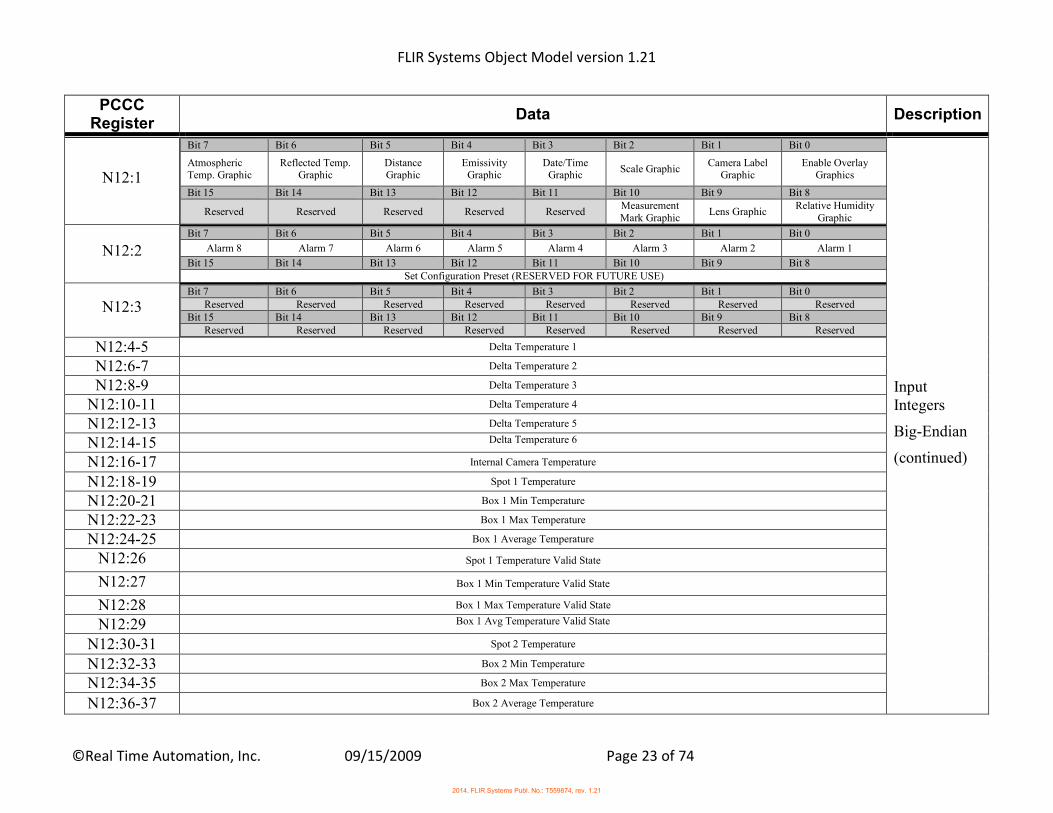
Table 1-9 PCCC Object (67HEX) Input Integers Big Endian– Read Only
PCCC Register
Data Description
N12:0
Bit 7 Bit 6 Bit 5 Bit 4 Bit 3 Bit 2 Bit 1 Bit 0
Reserved Force Image One
Shot Save Image
One Time Image Auto
Adjust
Auto Focus Fast
Auto Focus Full
Force NUC
Auto NUC
Bit 15 Bit 14 Bit 13 Bit 12 Bit 11 Bit 10 Bit 9 Bit 8
Disable Alarm1 Reserved Image Live Image Freeze DI 2 DI 1 DO 2 DO 1
Input Integers
Big-Endian
1 This alarm is the BATCH alarm. It has the ability to enable or disable all the other 8 alarms.
2014, FLIR Systems Publ. No.: T559874, rev. 1.21
FLIR Systems Object Model version 1.21
©Real Time Automation, Inc. 09/15/2009 Page 23 of 74
PCCC Register
Data Description
N12:1
Bit 7 Bit 6 Bit 5 Bit 4 Bit 3 Bit 2 Bit 1 Bit 0
Atmospheric Temp. Graphic
Reflected Temp. Graphic
Distance Graphic
Emissivity Graphic
Date/Time Graphic
Scale Graphic Camera Label
Graphic Enable Overlay
Graphics
Bit 15 Bit 14 Bit 13 Bit 12 Bit 11 Bit 10 Bit 9 Bit 8
Reserved Reserved Reserved Reserved Reserved Measurement Mark Graphic
Lens Graphic Relative Humidity
Graphic
Input Integers
Big-Endian
(continued)
N12:2
Bit 7 Bit 6 Bit 5 Bit 4 Bit 3 Bit 2 Bit 1 Bit 0
Alarm 8 Alarm 7 Alarm 6 Alarm 5 Alarm 4 Alarm 3 Alarm 2 Alarm 1
Bit 15 Bit 14 Bit 13 Bit 12 Bit 11 Bit 10 Bit 9 Bit 8 Set Configuration Preset (RESERVED FOR FUTURE USE)
N12:3
Bit 7 Bit 6 Bit 5 Bit 4 Bit 3 Bit 2 Bit 1 Bit 0 Reserved Reserved Reserved Reserved Reserved Reserved Reserved Reserved
Bit 15 Bit 14 Bit 13 Bit 12 Bit 11 Bit 10 Bit 9 Bit 8 Reserved Reserved Reserved Reserved Reserved Reserved Reserved Reserved
N12:4-5 Delta Temperature 1
N12:6-7 Delta Temperature 2
N12:8-9 Delta Temperature 3
N12:10-11 Delta Temperature 4
N12:12-13 Delta Temperature 5
N12:14-15 Delta Temperature 6
N12:16-17 Internal Camera Temperature
N12:18-19 Spot 1 Temperature
N12:20-21 Box 1 Min Temperature
N12:22-23 Box 1 Max Temperature
N12:24-25 Box 1 Average Temperature
N12:26 Spot 1 Temperature Valid State
N12:27 Box 1 Min Temperature Valid State
N12:28 Box 1 Max Temperature Valid State
N12:29 Box 1 Avg Temperature Valid State
N12:30-31 Spot 2 Temperature
N12:32-33 Box 2 Min Temperature
N12:34-35 Box 2 Max Temperature
N12:36-37 Box 2 Average Temperature
2014, FLIR Systems Publ. No.: T559874, rev. 1.21
FLIR Systems Object Model version 1.21
©Real Time Automation, Inc. 09/15/2009 Page 24 of 74
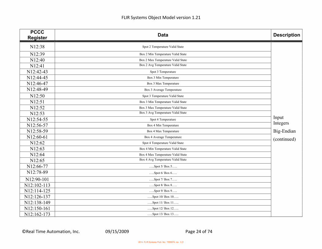
PCCC Register
Data Description
N12:38 Spot 2 Temperature Valid State
Input Integers
Big-Endian
(continued)
N12:39 Box 2 Min Temperature Valid State
N12:40 Box 2 Max Temperature Valid State
N12:41 Box 2 Avg Temperature Valid State
N12:42-43 Spot 3 Temperature
N12:44-45 Box 3 Min Temperature
N12:46-47 Box 3 Max Temperature
N12:48-49 Box 3 Average Temperature
N12:50 Spot 3 Temperature Valid State
N12:51 Box 3 Min Temperature Valid State
N12:52 Box 3 Max Temperature Valid State
N12:53 Box 3 Avg Temperature Valid State
N12:54-55 Spot 4 Temperature
N12:56-57 Box 4 Min Temperature
N12:58-59 Box 4 Max Temperature
N12:60-61 Box 4 Average Temperature
N12:62 Spot 4 Temperature Valid State
N12:63 Box 4 Min Temperature Valid State
N12:64 Box 4 Max Temperature Valid State
N12:65 Box 4 Avg Temperature Valid State
N12:66-77 …..Spot 5/ Box 5…..
N12:78-89 …..Spot 6/ Box 6…..
N12:90-101 …..Spot 7/ Box 7…..
N12:102-113 …..Spot 8/ Box 8…..
N12:114-125 …..Spot 9/ Box 9…..
N12:126-137 …..Spot 10/ Box 10…..
N12:138-149 …..Spot 11/ Box 11…..
N12:150-161 …..Spot 12/ Box 12…..
N12:162-173 …..Spot 13/ Box 13…..
2014, FLIR Systems Publ. No.: T559874, rev. 1.21
FLIR Systems Object Model version 1.21
©Real Time Automation, Inc. 09/15/2009 Page 25 of 74
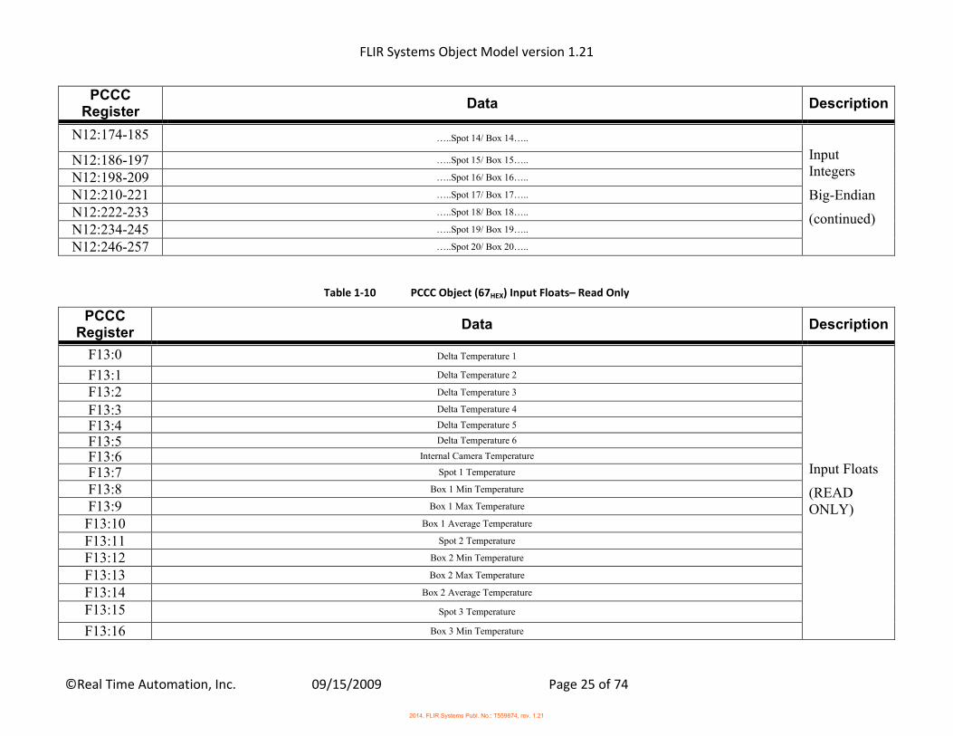
PCCC Register
Data Description
N12:174-185 …..Spot 14/ Box 14…..
Input Integers
Big-Endian
(continued)
N12:186-197 …..Spot 15/ Box 15…..
N12:198-209 …..Spot 16/ Box 16…..
N12:210-221 …..Spot 17/ Box 17…..
N12:222-233 …..Spot 18/ Box 18…..
N12:234-245 …..Spot 19/ Box 19…..
N12:246-257 …..Spot 20/ Box 20…..
Table 1-10 PCCC Object (67HEX) Input Floats– Read Only
PCCC Register
Data Description
F13:0 Delta Temperature 1
Input Floats
(READ ONLY)
F13:1 Delta Temperature 2
F13:2 Delta Temperature 3
F13:3 Delta Temperature 4
F13:4 Delta Temperature 5
F13:5 Delta Temperature 6
F13:6 Internal Camera Temperature
F13:7 Spot 1 Temperature
F13:8 Box 1 Min Temperature
F13:9 Box 1 Max Temperature
F13:10 Box 1 Average Temperature
F13:11 Spot 2 Temperature
F13:12 Box 2 Min Temperature
F13:13 Box 2 Max Temperature
F13:14 Box 2 Average Temperature
F13:15 Spot 3 Temperature
F13:16 Box 3 Min Temperature
2014, FLIR Systems Publ. No.: T559874, rev. 1.21
FLIR Systems Object Model version 1.21
©Real Time Automation, Inc. 09/15/2009 Page 26 of 74
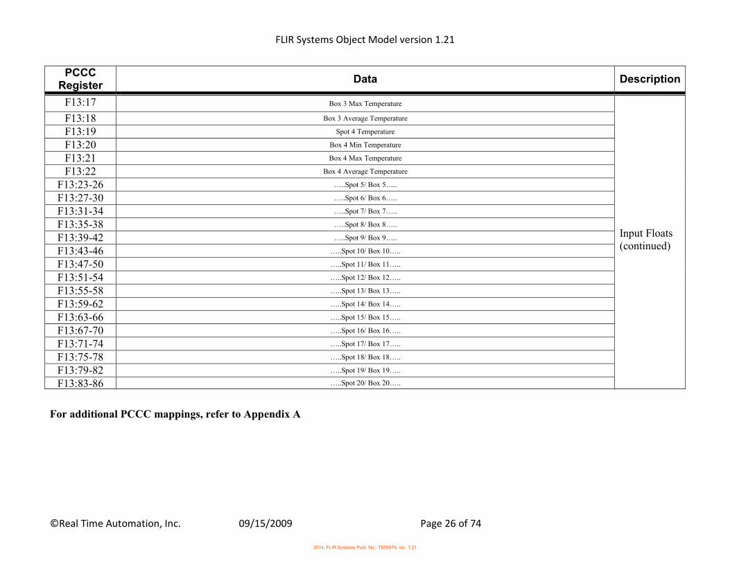
PCCC Register
Data Description
F13:17 Box 3 Max Temperature
Input Floats (continued)
F13:18 Box 3 Average Temperature
F13:19 Spot 4 Temperature
F13:20 Box 4 Min Temperature
F13:21 Box 4 Max Temperature
F13:22 Box 4 Average Temperature
F13:23-26 …..Spot 5/ Box 5…..
F13:27-30 …..Spot 6/ Box 6…..
F13:31-34 …..Spot 7/ Box 7…..
F13:35-38 …..Spot 8/ Box 8…..
F13:39-42 …..Spot 9/ Box 9…..
F13:43-46 …..Spot 10/ Box 10…..
F13:47-50 …..Spot 11/ Box 11…..
F13:51-54 …..Spot 12/ Box 12…..
F13:55-58 …..Spot 13/ Box 13…..
F13:59-62 …..Spot 14/ Box 14…..
F13:63-66 …..Spot 15/ Box 15…..
F13:67-70 …..Spot 16/ Box 16…..
F13:71-74 …..Spot 17/ Box 17…..
F13:75-78 …..Spot 18/ Box 18…..
F13:79-82 …..Spot 19/ Box 19…..
F13:83-86 …..Spot 20/ Box 20…..
For additional PCCC mappings, refer to Appendix A
2014, FLIR Systems Publ. No.: T559874, rev. 1.21
FLIR Systems Object Model version 1.21
©Real Time Automation, Inc. 09/15/2009 Page 27 of 74
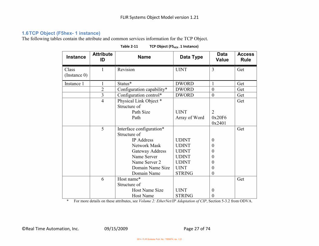
1.6 TCP Object (F5hex- 1 instance) The following tables contain the attribute and common services information for the TCP Object.
Table 2-11 TCP Object (F5HEX - 1 Instance)
Instance Attribute
ID Name Data Type
Data Value
Access Rule
Class (Instance 0)
1 Revision UINT 3 Get
Instance 1 1 Status* DWORD 1 Get 2 Configuration capability* DWORD 0 Get 3 Configuration control* DWORD 0 Get 4 Physical Link Object *
Structure of Path Size Path
UINT Array of Word
2 0x20F6 0x2401
Get
5 Interface configuration* Structure of IP Address Network Mask Gateway Address Name Server Name Server 2 Domain Name Size Domain Name
UDINT UDINT UDINT UDINT UDINT UINT STRING
0 0 0 0 0 0 0
Get
6 Host name* Structure of Host Name Size Host Name
UINT STRING
0 0
Get
* For more details on these attributes, see Volume 2: EtherNet/IP Adaptation of CIP, Section 5-3.2 from ODVA.
2014, FLIR Systems Publ. No.: T559874, rev. 1.21
FLIR Systems Object Model version 1.21
©Real Time Automation, Inc. 09/15/2009 Page 28 of 74
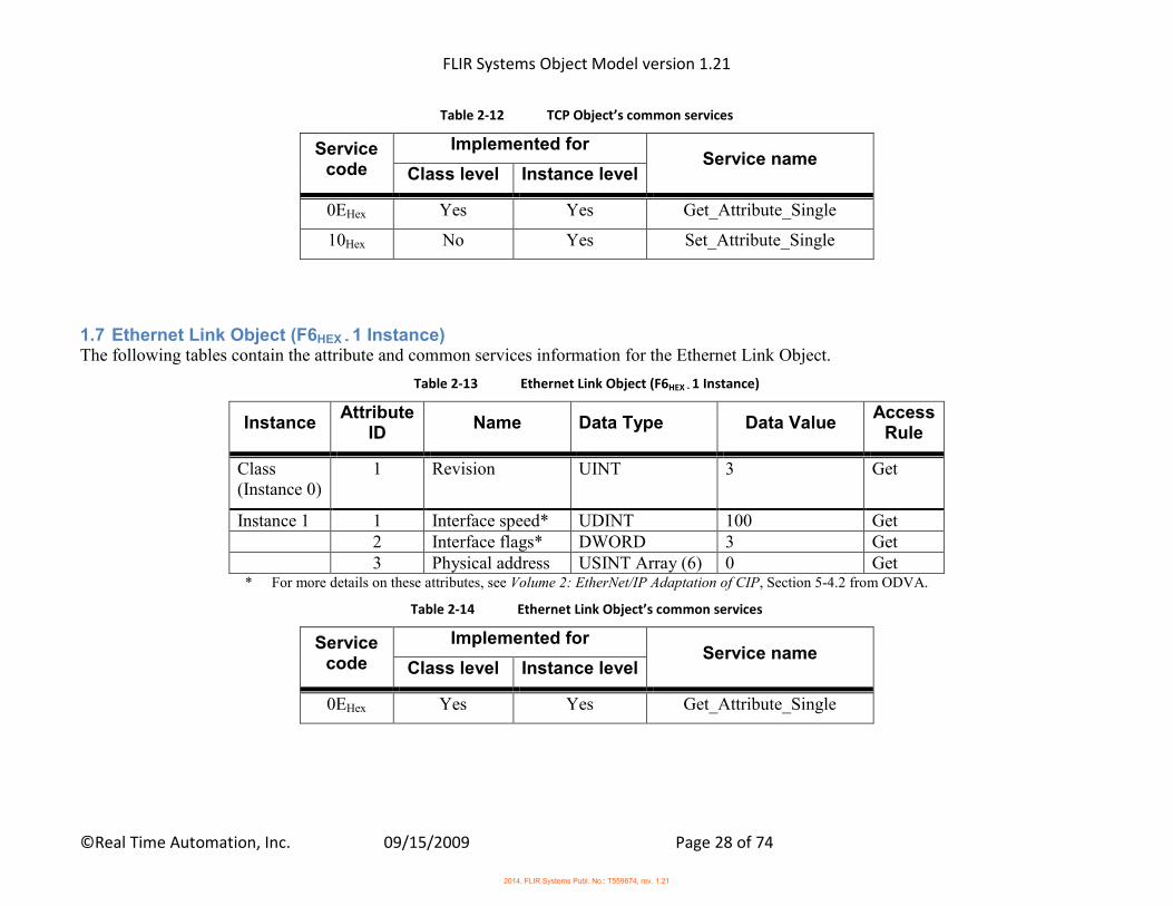
Table 2-12 TCP Object’s common services
Service code
Implemented for Service name
Class level Instance level
0EHex Yes Yes Get_Attribute_Single
10Hex No Yes Set_Attribute_Single
1.7 Ethernet Link Object (F6HEX - 1 Instance) The following tables contain the attribute and common services information for the Ethernet Link Object.
Table 2-13 Ethernet Link Object (F6HEX - 1 Instance)
Instance Attribute
ID Name Data Type Data Value
Access Rule
Class (Instance 0)
1 Revision UINT 3 Get
Instance 1 1 Interface speed* UDINT 100 Get 2 Interface flags* DWORD 3 Get 3 Physical address USINT Array (6) 0 Get
* For more details on these attributes, see Volume 2: EtherNet/IP Adaptation of CIP, Section 5-4.2 from ODVA.
Table 2-14 Ethernet Link Object’s common services
Service code
Implemented for Service name
Class level Instance level
0EHex Yes Yes Get_Attribute_Single
2014, FLIR Systems Publ. No.: T559874, rev. 1.21
FLIR Systems Object Model version 1.21
©Real Time Automation, Inc. 09/15/2009 Page 29 of 74
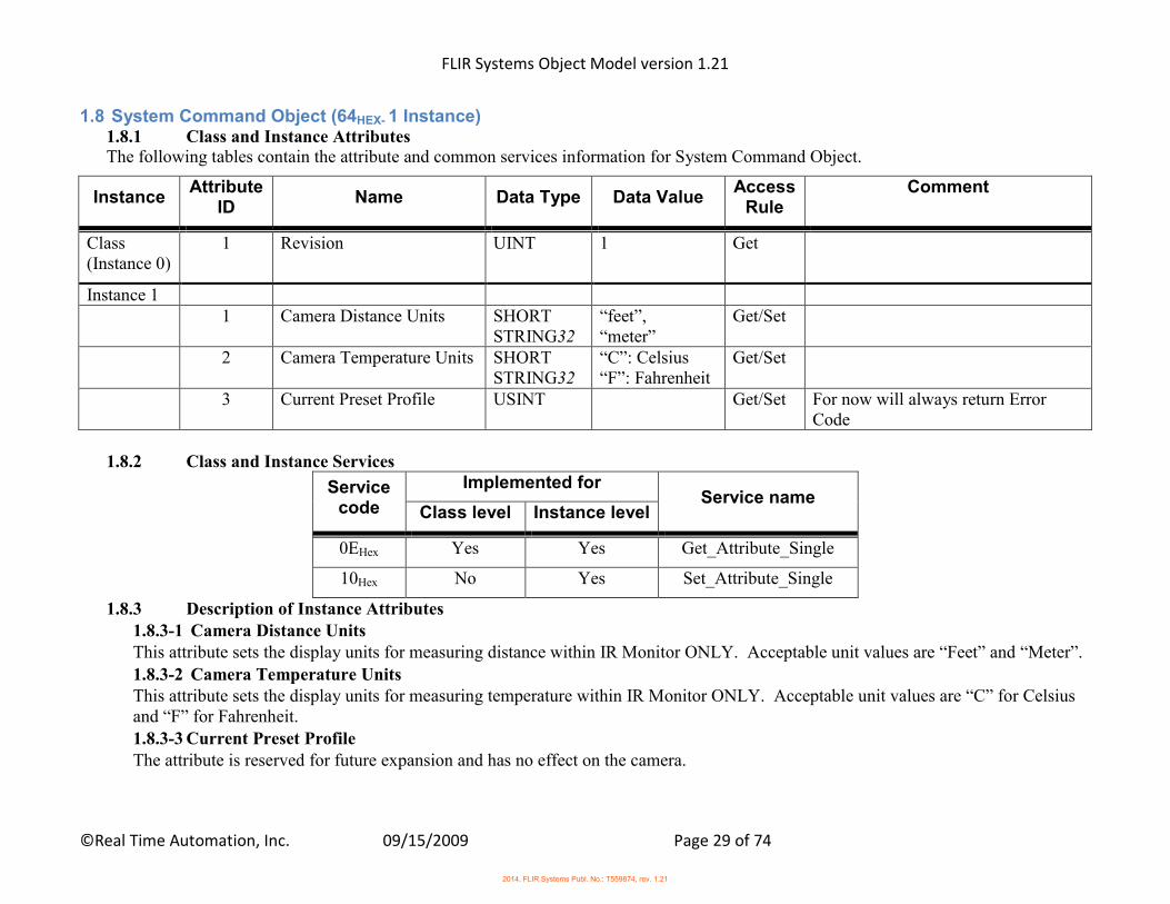
1.8 System Command Object (64HEX- 1 Instance) 1.8.1 Class and Instance Attributes The following tables contain the attribute and common services information for System Command Object.
Instance Attribute
ID Name Data Type Data Value
Access Rule
Comment
Class (Instance 0)
1 Revision UINT 1 Get
Instance 1 1 Camera Distance Units SHORT
STRING32 “feet”, “meter”
Get/Set
2 Camera Temperature Units SHORT STRING32
“C”: Celsius “F”: Fahrenheit
Get/Set
3 Current Preset Profile USINT Get/Set For now will always return Error Code
1.8.2 Class and Instance Services
Service code
Implemented for Service name
Class level Instance level
0EHex Yes Yes Get_Attribute_Single
10Hex No Yes Set_Attribute_Single
1.8.3 Description of Instance Attributes 1.8.3-1 Camera Distance Units This attribute sets the display units for measuring distance within IR Monitor ONLY. Acceptable unit values are “Feet” and “Meter”.
1.8.3-2 Camera Temperature Units This attribute sets the display units for measuring temperature within IR Monitor ONLY. Acceptable unit values are “C” for Celsius and “F” for Fahrenheit. 1.8.3-3 Current Preset Profile The attribute is reserved for future expansion and has no effect on the camera.
2014, FLIR Systems Publ. No.: T559874, rev. 1.21
FLIR Systems Object Model version 1.21
©Real Time Automation, Inc. 09/15/2009 Page 30 of 74
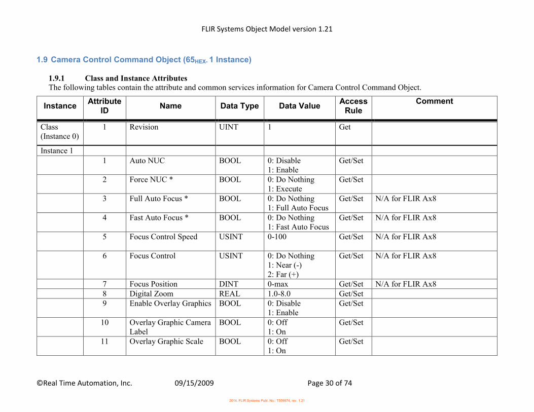
1.9 Camera Control Command Object (65HEX- 1 Instance)
1.9.1 Class and Instance Attributes The following tables contain the attribute and common services information for Camera Control Command Object.
Instance Attribute
ID Name Data Type Data Value
Access Rule
Comment
Class (Instance 0)
1 Revision UINT 1 Get
Instance 1 1 Auto NUC BOOL 0: Disable
1: Enable Get/Set
2 Force NUC * BOOL 0: Do Nothing 1: Execute
Get/Set
3 Full Auto Focus * BOOL 0: Do Nothing 1: Full Auto Focus
Get/Set N/A for FLIR Ax8
4 Fast Auto Focus * BOOL 0: Do Nothing 1: Fast Auto Focus
Get/Set N/A for FLIR Ax8
5 Focus Control Speed USINT 0-100 Get/Set N/A for FLIR Ax8
6 Focus Control USINT 0: Do Nothing 1: Near (-) 2: Far (+)
Get/Set N/A for FLIR Ax8
7 Focus Position DINT 0-max Get/Set N/A for FLIR Ax8 8 Digital Zoom REAL 1.0-8.0 Get/Set 9 Enable Overlay Graphics BOOL 0: Disable
1: Enable Get/Set
10 Overlay Graphic Camera Label
BOOL 0: Off 1: On
Get/Set
11 Overlay Graphic Scale BOOL 0: Off 1: On
Get/Set
2014, FLIR Systems Publ. No.: T559874, rev. 1.21
FLIR Systems Object Model version 1.21
©Real Time Automation, Inc. 09/15/2009 Page 31 of 74
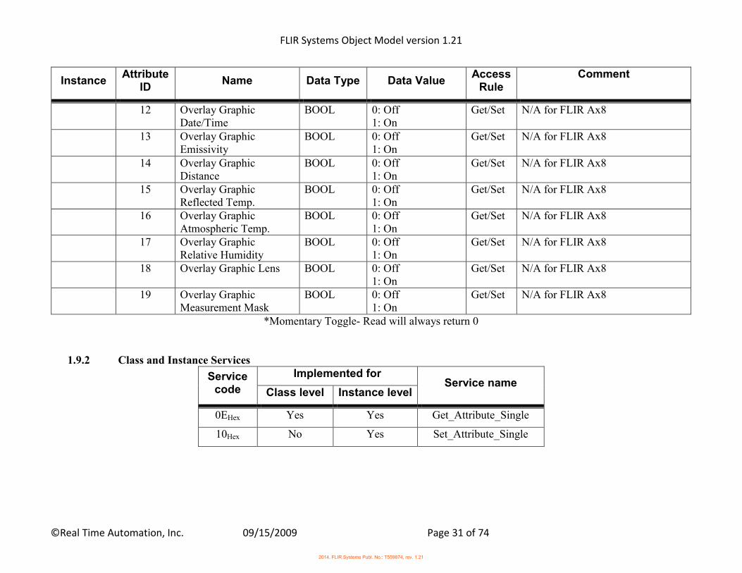
Instance Attribute
ID Name Data Type Data Value
Access Rule
Comment
12 Overlay Graphic Date/Time
BOOL 0: Off 1: On
Get/Set N/A for FLIR Ax8
13 Overlay Graphic Emissivity
BOOL 0: Off 1: On
Get/Set N/A for FLIR Ax8
14 Overlay Graphic Distance
BOOL 0: Off 1: On
Get/Set N/A for FLIR Ax8
15 Overlay Graphic Reflected Temp.
BOOL 0: Off 1: On
Get/Set N/A for FLIR Ax8
16 Overlay Graphic Atmospheric Temp.
BOOL 0: Off 1: On
Get/Set N/A for FLIR Ax8
17 Overlay Graphic Relative Humidity
BOOL 0: Off 1: On
Get/Set N/A for FLIR Ax8
18 Overlay Graphic Lens BOOL 0: Off 1: On
Get/Set N/A for FLIR Ax8
19 Overlay Graphic Measurement Mask
BOOL 0: Off 1: On
Get/Set N/A for FLIR Ax8
*Momentary Toggle- Read will always return 0
1.9.2 Class and Instance Services
Service code
Implemented for Service name
Class level Instance level
0EHex Yes Yes Get_Attribute_Single
10Hex No Yes Set_Attribute_Single
2014, FLIR Systems Publ. No.: T559874, rev. 1.21
FLIR Systems Object Model version 1.21
©Real Time Automation, Inc. 09/15/2009 Page 32 of 74
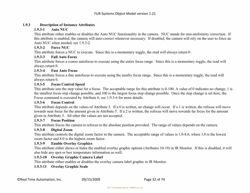
1.9.3 Description of Instance Attributes 1.9.3-1 Auto NUC This attribute either enables or disables the Auto NUC functionality in the camera. NUC stands for non-uniformity correction. If this attribute is enabled, the camera will auto-correct whenever necessary. If disabled, the camera will rely on the user to force an Auto NUC when needed, see 1.9.3-2. 1.9.3-2 Force NUC This attribute forces a NUC to execute. Since this is a momentary toggle, the read will always return 0.
1.9.3-3 Full Auto Focus This attribute forces a coarse autofocus to execute using the entire focus range. Since this is a momentary toggle, the read will always return 0. 1.9.3-4 Fast Auto Focus This attribute forces a fine autofocus to execute using the nearby focus range. Since this is a momentary toggle, the read will always return 0. 1.9.3-5 Focus Control Speed This attribute sets the step value for a focus. The acceptable range for this attribute is 0-100. A value of 0 indicates no change, 1 is the smallest focus step change possible, and 100 is the largest focus step change possible. Once the step change is set here, the Focus command is executed by Attribute 6, see 1.9.3-6 for more details.
1.9.3-6 Focus Control This attribute depends on the values of Attribute 5. If a 0 is written, no change will occur. If a 1 is written, the refocus will move towards near focus for the amount given in Attribute 5. If a 2 is written, the refocus will move towards far focus for the amount given in Attribute 5. All other the values are not accepted. 1.9.3-7 Focus Position This attribute forces the camera to refocus to the absolute position provided. The range of values depends on the camera.
1.9.3-8 Digital Zoom This attribute controls the digital zoom factor in the camera. The acceptable range of values is 1.0-8.0, where 1.0 is the lowest zoom factor and 8.0 is the highest zoom factor. 1.9.3-9 Enable Overlay Graphics This attribute either shows or hides the enabled overlay graphic options (Atributes 10-19) in IR Monitor. If this is disabled, it will also hide any spot or box temperature information as well. 1.9.3-10 Overlay Graphic Camera Label This attribute either enables or disables the overlay camera label graphic in IR Monitor.
1.9.3-11 Overlay Graphic Scale
2014, FLIR Systems Publ. No.: T559874, rev. 1.21

FLIR Systems Object Model version 1.21
©Real Time Automation, Inc. 09/15/2009 Page 33 of 74
This attribute either enables or disables the overlay camera scale graphic in IR Monitor. 1.9.3-12 Overlay Graphic Date/Time This attribute either enables or disables the overlay camera date and time graphic in IR Monitor. 1.9.3-13 Overlay Graphic Emissivity This attribute either enables or disables the overlay camera emissivity graphic in IR Monitor.
1.9.3-14 Overlay Graphic Distance This attribute either enables or disables the overlay camera distance graphic in IR Monitor. 1.9.3-15 Overlay Graphic Reflected Temp. This attribute either enables or disables the overlay camera reflected temperature graphic in IR Monitor. 1.9.3-16 Overlay Graphic Atmospheric Temp. This attribute either enables or disables the overlay camera atmospheric temperature graphic in IR Monitor.
1.9.3-17 Overlay Graphic Relative Humidity This attribute either enables or disables the overlay camera relative humidity graphic in IR Monitor. 1.9.3-18 Overlay Graphic Lens This attribute either enables or disables the overlay camera lens graphic in IR Monitor. 1.9.3-19 Overlay Graphic Measurement Mask This attribute either enables or disables the overlay camera measurement mask graphic in IR Monitor.
2014, FLIR Systems Publ. No.: T559874, rev. 1.21
FLIR Systems Object Model version 1.21
©Real Time Automation, Inc. 09/15/2009 Page 34 of 74
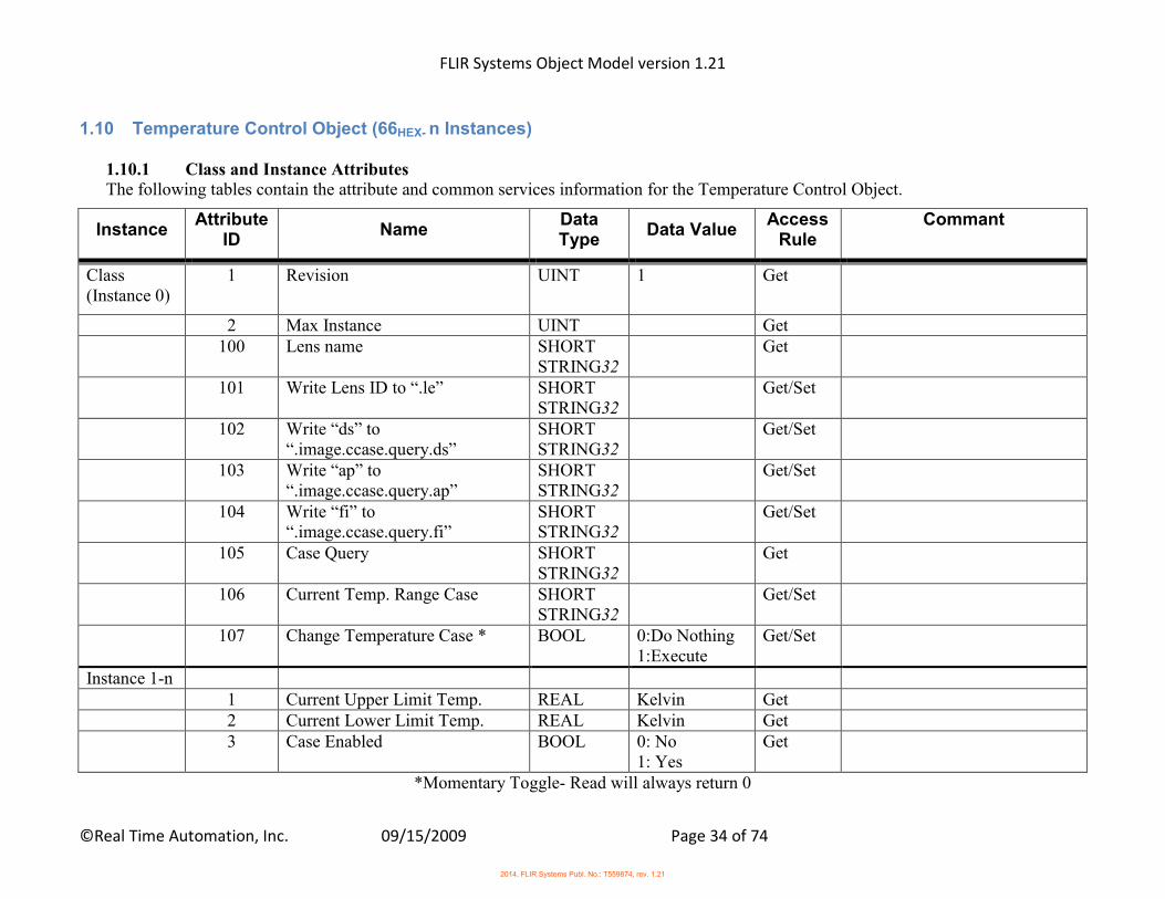
1.10 Temperature Control Object (66HEX- n Instances)
1.10.1 Class and Instance Attributes The following tables contain the attribute and common services information for the Temperature Control Object.
Instance Attribute
ID Name
Data Type
Data Value Access
Rule Commant
Class (Instance 0)
1 Revision UINT 1 Get
2 Max Instance UINT Get 100 Lens name SHORT
STRING32 Get
101 Write Lens ID to “.le” SHORT STRING32
Get/Set
102 Write “ds” to “.image.ccase.query.ds”
SHORT STRING32
Get/Set
103 Write “ap” to “.image.ccase.query.ap”
SHORT STRING32
Get/Set
104 Write “fi” to “.image.ccase.query.fi”
SHORT STRING32
Get/Set
105 Case Query SHORT STRING32
Get
106 Current Temp. Range Case SHORT STRING32
Get/Set
107 Change Temperature Case * BOOL 0:Do Nothing 1:Execute
Get/Set
Instance 1-n 1 Current Upper Limit Temp. REAL Kelvin Get 2 Current Lower Limit Temp. REAL Kelvin Get 3 Case Enabled BOOL 0: No
1: Yes Get
*Momentary Toggle- Read will always return 0
2014, FLIR Systems Publ. No.: T559874, rev. 1.21
FLIR Systems Object Model version 1.21
©Real Time Automation, Inc. 09/15/2009 Page 35 of 74
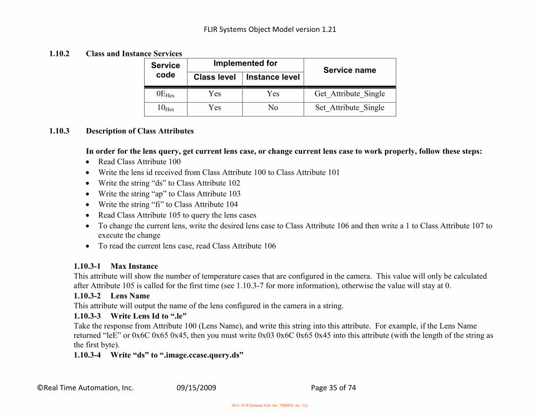
1.10.2 Class and Instance Services
Service code
Implemented for Service name
Class level Instance level
0EHex Yes Yes Get_Attribute_Single
10Hex Yes No Set_Attribute_Single
1.10.3 Description of Class Attributes
In order for the lens query, get current lens case, or change current lens case to work properly, follow these steps:
Read Class Attribute 100
Write the lens id received from Class Attribute 100 to Class Attribute 101
Write the string “ds” to Class Attribute 102
Write the string “ap” to Class Attribute 103
Write the string “fi” to Class Attribute 104
Read Class Attribute 105 to query the lens cases
To change the current lens, write the desired lens case to Class Attribute 106 and then write a 1 to Class Attribute 107 to execute the change
To read the current lens case, read Class Attribute 106
1.10.3-1 Max Instance This attribute will show the number of temperature cases that are configured in the camera. This value will only be calculated after Attribute 105 is called for the first time (see 1.10.3-7 for more information), otherwise the value will stay at 0. 1.10.3-2 Lens Name This attribute will output the name of the lens configured in the camera in a string.
1.10.3-3 Write Lens Id to “.le” Take the response from Attribute 100 (Lens Name), and write this string into this attribute. For example, if the Lens Name returned “leE” or 0x6C 0x65 0x45, then you must write 0x03 0x6C 0x65 0x45 into this attribute (with the length of the string as the first byte). 1.10.3-4 Write “ds” to “.image.ccase.query.ds”
2014, FLIR Systems Publ. No.: T559874, rev. 1.21
FLIR Systems Object Model version 1.21
©Real Time Automation, Inc. 09/15/2009 Page 36 of 74
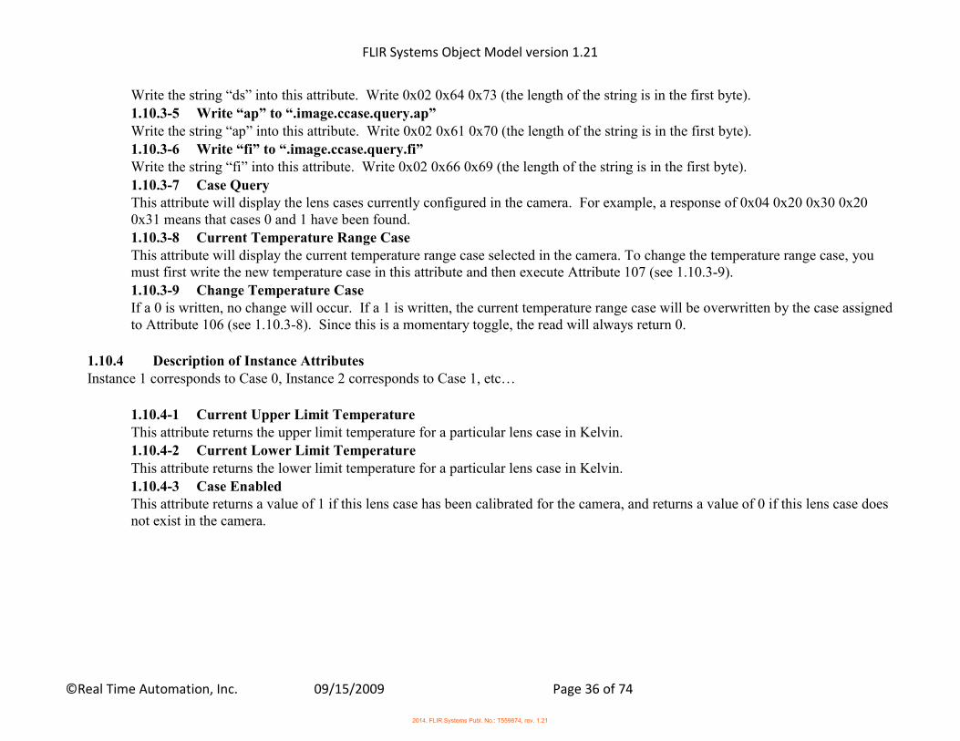
Write the string “ds” into this attribute. Write 0x02 0x64 0x73 (the length of the string is in the first byte). 1.10.3-5 Write “ap” to “.image.ccase.query.ap” Write the string “ap” into this attribute. Write 0x02 0x61 0x70 (the length of the string is in the first byte). 1.10.3-6 Write “fi” to “.image.ccase.query.fi” Write the string “fi” into this attribute. Write 0x02 0x66 0x69 (the length of the string is in the first byte).
1.10.3-7 Case Query This attribute will display the lens cases currently configured in the camera. For example, a response of 0x04 0x20 0x30 0x20 0x31 means that cases 0 and 1 have been found. 1.10.3-8 Current Temperature Range Case This attribute will display the current temperature range case selected in the camera. To change the temperature range case, you must first write the new temperature case in this attribute and then execute Attribute 107 (see 1.10.3-9). 1.10.3-9 Change Temperature Case If a 0 is written, no change will occur. If a 1 is written, the current temperature range case will be overwritten by the case assigned to Attribute 106 (see 1.10.3-8). Since this is a momentary toggle, the read will always return 0.
1.10.4 Description of Instance Attributes Instance 1 corresponds to Case 0, Instance 2 corresponds to Case 1, etc…
1.10.4-1 Current Upper Limit Temperature This attribute returns the upper limit temperature for a particular lens case in Kelvin. 1.10.4-2 Current Lower Limit Temperature This attribute returns the lower limit temperature for a particular lens case in Kelvin. 1.10.4-3 Case Enabled This attribute returns a value of 1 if this lens case has been calibrated for the camera, and returns a value of 0 if this lens case does not exist in the camera.
2014, FLIR Systems Publ. No.: T559874, rev. 1.21
FLIR Systems Object Model version 1.21
©Real Time Automation, Inc. 09/15/2009 Page 37 of 74
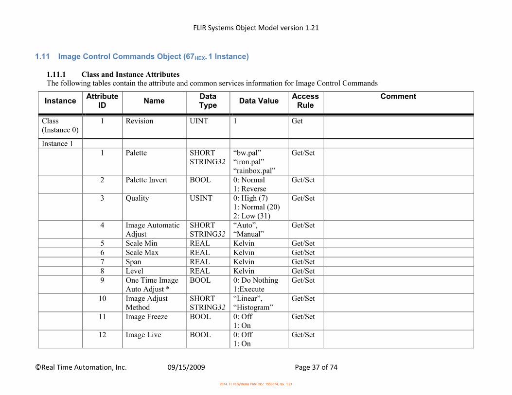
1.11 Image Control Commands Object (67HEX- 1 Instance)
1.11.1 Class and Instance Attributes The following tables contain the attribute and common services information for Image Control Commands
Instance Attribute
ID Name
Data Type
Data Value Access
Rule Comment
Class (Instance 0)
1 Revision UINT 1 Get
Instance 1 1 Palette SHORT
STRING32 “bw.pal” “iron.pal” “rainbox.pal”
Get/Set
2 Palette Invert BOOL 0: Normal 1: Reverse
Get/Set
3 Quality USINT 0: High (7) 1: Normal (20) 2: Low (31)
Get/Set
4 Image Automatic Adjust
SHORT STRING32
“Auto”, “Manual”
Get/Set
5 Scale Min REAL Kelvin Get/Set 6 Scale Max REAL Kelvin Get/Set 7 Span REAL Kelvin Get/Set 8 Level REAL Kelvin Get/Set 9 One Time Image
Auto Adjust * BOOL 0: Do Nothing
1:Execute Get/Set
10 Image Adjust Method
SHORT STRING32
“Linear”, “Histogram”
Get/Set
11 Image Freeze BOOL 0: Off 1: On
Get/Set
12 Image Live BOOL 0: Off 1: On
Get/Set
2014, FLIR Systems Publ. No.: T559874, rev. 1.21
FLIR Systems Object Model version 1.21
©Real Time Automation, Inc. 09/15/2009 Page 38 of 74
Instance Attribute
ID Name
Data Type
Data Value Access
Rule Comment
13 Image State SHORT STRING32
“LIVE”, “FREEZE”
Get
14 Image Measure Mode
BOOL 0:Normal 1:High Prio One Shot
Get/Set
15 Image Measurement One Shot *
BOOL 0: Do Nothing 1:Execute
Get/Set
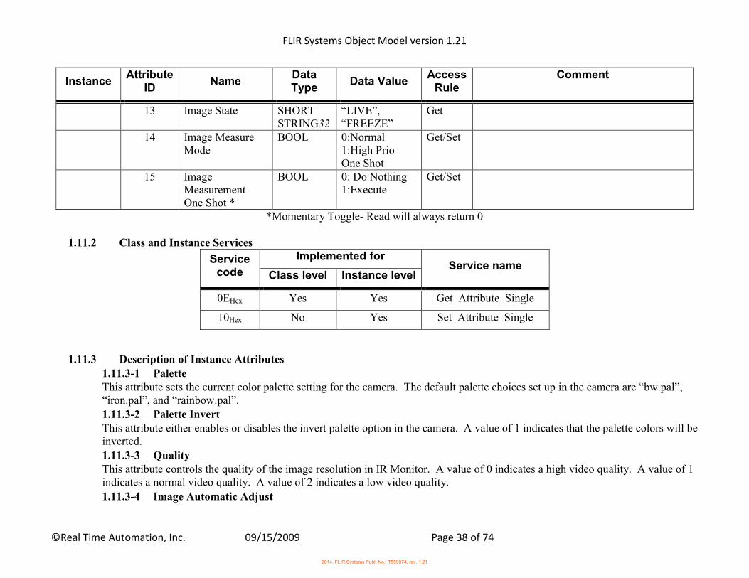
*Momentary Toggle- Read will always return 0
1.11.2 Class and Instance Services
Service code
Implemented for Service name
Class level Instance level
0EHex Yes Yes Get_Attribute_Single
10Hex No Yes Set_Attribute_Single
1.11.3 Description of Instance Attributes
1.11.3-1 Palette This attribute sets the current color palette setting for the camera. The default palette choices set up in the camera are “bw.pal”, “iron.pal”, and “rainbow.pal”. 1.11.3-2 Palette Invert This attribute either enables or disables the invert palette option in the camera. A value of 1 indicates that the palette colors will be inverted. 1.11.3-3 Quality This attribute controls the quality of the image resolution in IR Monitor. A value of 0 indicates a high video quality. A value of 1 indicates a normal video quality. A value of 2 indicates a low video quality.
1.11.3-4 Image Automatic Adjust
2014, FLIR Systems Publ. No.: T559874, rev. 1.21
FLIR Systems Object Model version 1.21
©Real Time Automation, Inc. 09/15/2009 Page 39 of 74
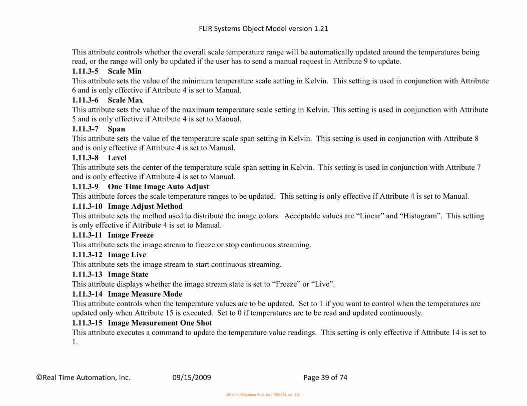
This attribute controls whether the overall scale temperature range will be automatically updated around the temperatures being read, or the range will only be updated if the user has to send a manual request in Attribute 9 to update. 1.11.3-5 Scale Min This attribute sets the value of the minimum temperature scale setting in Kelvin. This setting is used in conjunction with Attribute 6 and is only effective if Attribute 4 is set to Manual. 1.11.3-6 Scale Max This attribute sets the value of the maximum temperature scale setting in Kelvin. This setting is used in conjunction with Attribute 5 and is only effective if Attribute 4 is set to Manual.
1.11.3-7 Span This attribute sets the value of the temperature scale span setting in Kelvin. This setting is used in conjunction with Attribute 8 and is only effective if Attribute 4 is set to Manual. 1.11.3-8 Level This attribute sets the center of the temperature scale span setting in Kelvin. This setting is used in conjunction with Attribute 7 and is only effective if Attribute 4 is set to Manual. 1.11.3-9 One Time Image Auto Adjust This attribute forces the scale temperature ranges to be updated. This setting is only effective if Attribute 4 is set to Manual.
1.11.3-10 Image Adjust Method This attribute sets the method used to distribute the image colors. Acceptable values are “Linear” and “Histogram”. This setting is only effective if Attribute 4 is set to Manual. 1.11.3-11 Image Freeze This attribute sets the image stream to freeze or stop continuous streaming.
1.11.3-12 Image Live This attribute sets the image stream to start continuous streaming. 1.11.3-13 Image State This attribute displays whether the image stream state is set to “Freeze” or “Live”. 1.11.3-14 Image Measure Mode This attribute controls when the temperature values are to be updated. Set to 1 if you want to control when the temperatures are updated only when Attribute 15 is executed. Set to 0 if temperatures are to be read and updated continuously.
1.11.3-15 Image Measurement One Shot This attribute executes a command to update the temperature value readings. This setting is only effective if Attribute 14 is set to 1.
2014, FLIR Systems Publ. No.: T559874, rev. 1.21

FLIR Systems Object Model version 1.21
©Real Time Automation, Inc. 09/15/2009 Page 40 of 74
1.12 Isotherm Control Commands Object (68HEX- 1 Instance) 1.12.1 Class and Instance Attributes The following tables contain the attribute and common services information for Isotherm Control Commands
Instance Attribute
ID Name
Data Type
Data Value
Access Rule
Comment
Class (Instance 0)
1 Revision UINT 1 Get
2 Max Instance UINT Get
Instance 1 1 Isotherm Enable BOOL 0: Off
1: On Get/Set
2 Isotherm Type SHORT STRING32
“Above” “Below”
Get/Set
3 Isotherm Level REAL Kelvin Get/Set 4 Isotherm Color SHORT
STRING32 “palette1” “palette2” “red” “green” “blue” “yellow” “cyan” “magenta” “gray”
Get/Set
1.12.2 Class and Instance Services
2014, FLIR Systems Publ. No.: T559874, rev. 1.21
FLIR Systems Object Model version 1.21
©Real Time Automation, Inc. 09/15/2009 Page 41 of 74
Service code
Implemented for Service name
Class level Instance level
0EHex Yes Yes Get_Attribute_Single
10Hex No Yes Set_Attribute_Single
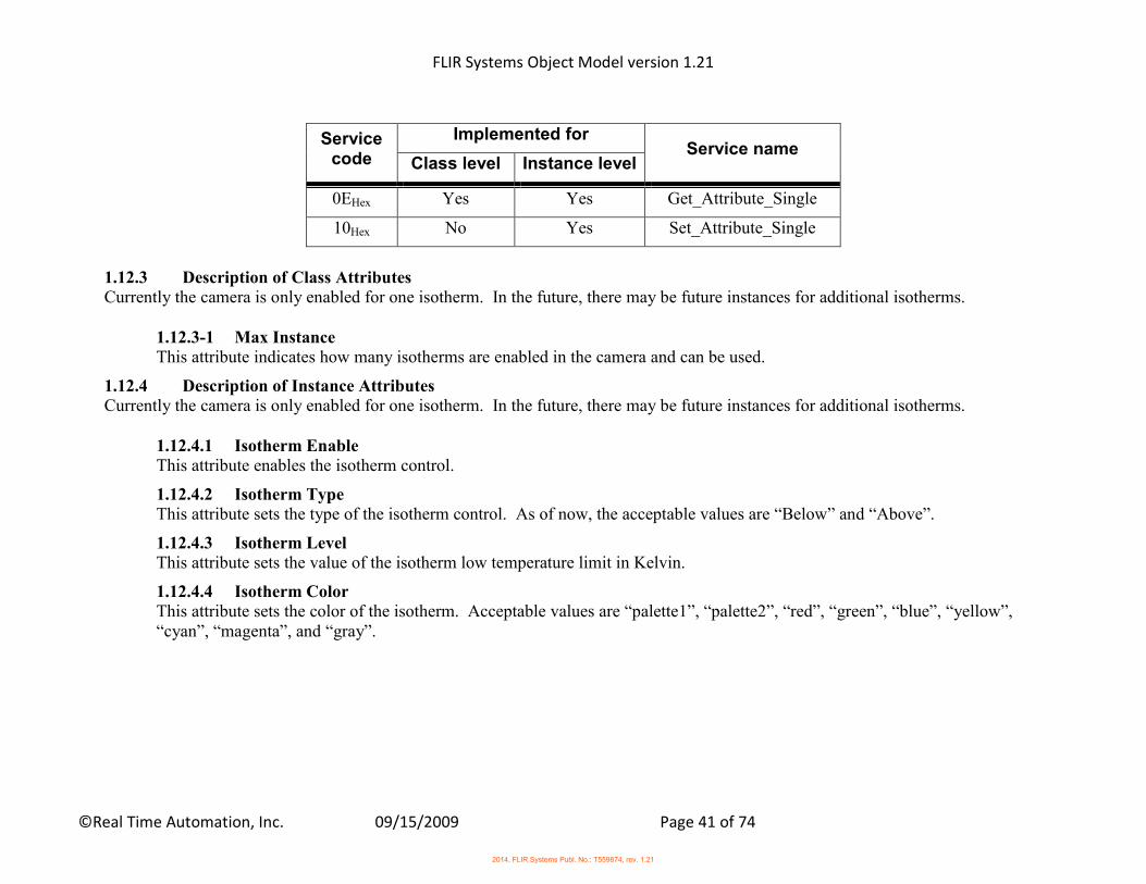
1.12.3 Description of Class Attributes Currently the camera is only enabled for one isotherm. In the future, there may be future instances for additional isotherms.
1.12.3-1 Max Instance This attribute indicates how many isotherms are enabled in the camera and can be used.
1.12.4 Description of Instance Attributes Currently the camera is only enabled for one isotherm. In the future, there may be future instances for additional isotherms.
1.12.4.1 Isotherm Enable This attribute enables the isotherm control.
1.12.4.2 Isotherm Type This attribute sets the type of the isotherm control. As of now, the acceptable values are “Below” and “Above”.
1.12.4.3 Isotherm Level This attribute sets the value of the isotherm low temperature limit in Kelvin.
1.12.4.4 Isotherm Color This attribute sets the color of the isotherm. Acceptable values are “palette1”, “palette2”, “red”, “green”, “blue”, “yellow”, “cyan”, “magenta”, and “gray”.
2014, FLIR Systems Publ. No.: T559874, rev. 1.21
FLIR Systems Object Model version 1.21
©Real Time Automation, Inc. 09/15/2009 Page 42 of 74
1.13 Image File Storage Object (69HEX- 1 Instance)
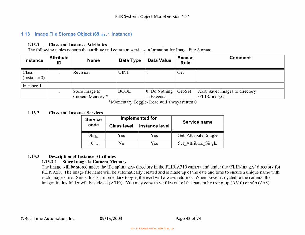
1.13.1 Class and Instance Attributes The following tables contain the attribute and common services information for Image File Storage.
Instance Attribute
ID Name Data Type Data Value
Access Rule
Comment
Class (Instance 0)
1 Revision UINT 1 Get
Instance 1 1 Store Image to
Camera Memory * BOOL 0: Do Nothing
1: Execute Get/Set Ax8: Saves images to directory
/FLIR/images *Momentary Toggle- Read will always return 0
1.13.2 Class and Instance Services
Service code
Implemented for Service name
Class level Instance level
0EHex Yes Yes Get_Attribute_Single
10Hex No Yes Set_Attribute_Single
1.13.3 Description of Instance Attributes
1.13.3-1 Store Image to Camera Memory The image will be stored under the \Temp\images\ directory in the FLIR A310 camera and under the /FLIR/images/ directory for FLIR Ax8. The image file name will be automatically created and is made up of the date and time to ensure a unique name with each image store. Since this is a momentary toggle, the read will always return 0. When power is cycled to the camera, the images in this folder will be deleted (A310). You may copy these files out of the camera by using ftp (A310) or sftp (Ax8).
2014, FLIR Systems Publ. No.: T559874, rev. 1.21
FLIR Systems Object Model version 1.21
©Real Time Automation, Inc. 09/15/2009 Page 43 of 74
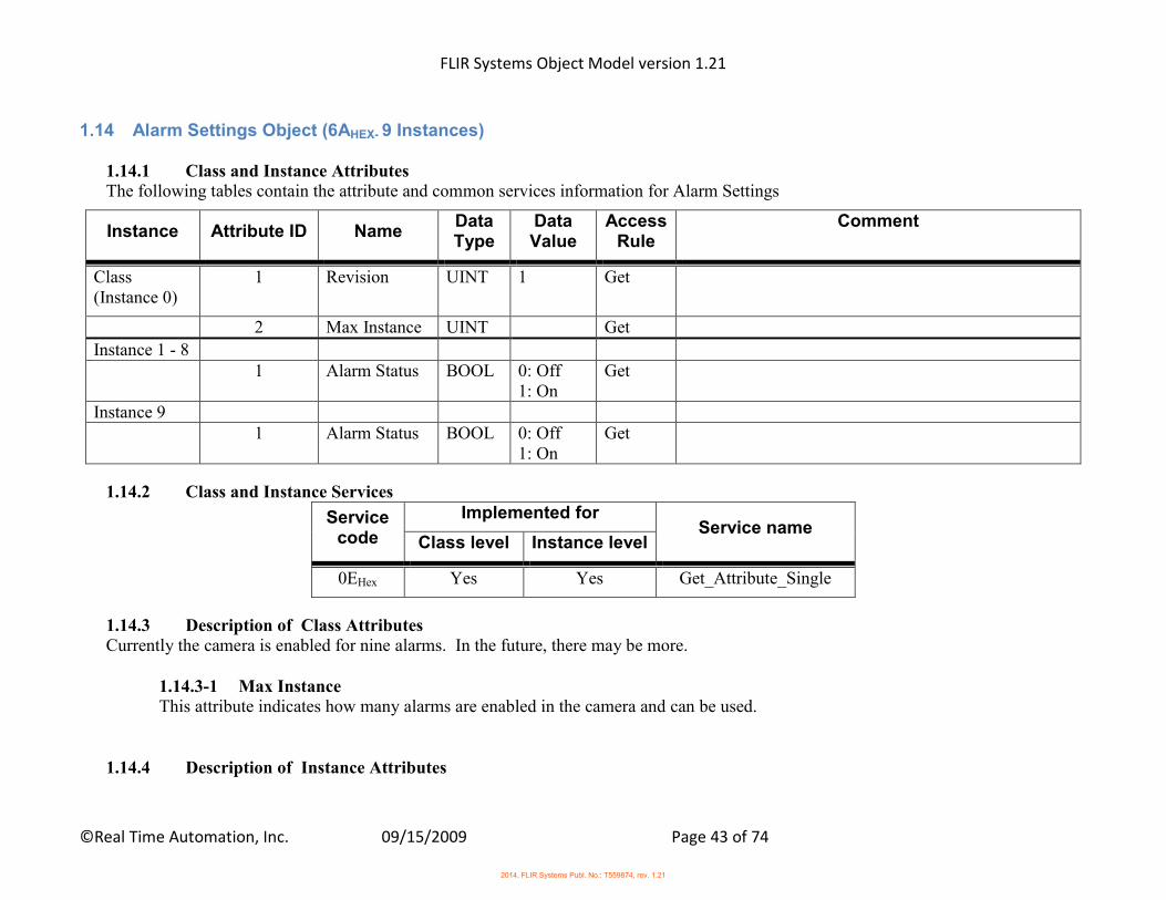
1.14 Alarm Settings Object (6AHEX- 9 Instances)
1.14.1 Class and Instance Attributes The following tables contain the attribute and common services information for Alarm Settings
Instance Attribute ID Name Data Type
Data Value
Access Rule
Comment
Class (Instance 0)
1 Revision UINT 1 Get
2 Max Instance UINT Get
Instance 1 - 8 1 Alarm Status BOOL 0: Off
1: On Get
Instance 9 1 Alarm Status BOOL 0: Off
1: On Get
1.14.2 Class and Instance Services
Service code
Implemented for Service name
Class level Instance level
0EHex Yes Yes Get_Attribute_Single
1.14.3 Description of Class Attributes Currently the camera is enabled for nine alarms. In the future, there may be more.
1.14.3-1 Max Instance This attribute indicates how many alarms are enabled in the camera and can be used.
1.14.4 Description of Instance Attributes
2014, FLIR Systems Publ. No.: T559874, rev. 1.21
FLIR Systems Object Model version 1.21
©Real Time Automation, Inc. 09/15/2009 Page 44 of 74
Each instance corresponds to a different Alarm within the camera. Instance 1 is Alarm 1, Instance 2 is Alarm 2, etc…. Instance 9 is the Batch Alarm. The Batch Alarm is used to enable and disable the output of the other active alarms.
1.14.4-1 Alarm Status This attribute displays whether an alarm condition state is active or not.
2014, FLIR Systems Publ. No.: T559874, rev. 1.21

FLIR Systems Object Model version 1.21
©Real Time Automation, Inc. 09/15/2009 Page 45 of 74
1.15 Object Parameters Object (6BHEX- 1 Instance)
1.15.1 Class and Instance Attributes The following tables contain the attribute and common services information for Object Parameters.
Instance Attribute
ID Name Data Type
Data Value
Access Rule
Comment
Class (Instance 0)
1 Revision UINT 1 Get
Instance 1 1 Atmosphere
Temperature REAL Kelvin Get/Set
2 Emissivity REAL 0.001-1.0 Get/Set 3 Distance REAL Meters Get/Set 4 Reflected
Temp REAL Kelvin Get/Set
5 Relative Humidity
REAL 0.0-1.0 Get/Set
6 Window Transmission Rate
REAL 0.001-1.0 Get/Set
7 Window Temperature
REAL Kelvin Get/Set
1.15.2 Class and Instance Services
Service code
Implemented for Service name
Class level Instance level
0EHex Yes Yes Get_Attribute_Single
10Hex No Yes Set_Attribute_Single
2014, FLIR Systems Publ. No.: T559874, rev. 1.21
FLIR Systems Object Model version 1.21
©Real Time Automation, Inc. 09/15/2009 Page 46 of 74
1.15.3 Description of Instance Attributes 1.15.3-1 Atmosphere Temperature This attribute sets the value of atmospheric temperature in Kelvin. 1.15.3-2 Emissivity This attribute sets the value of object emissivity. Accepted range is from 0.001 to 1.0.
1.15.3-3 Distance This attribute sets the value of the distance to the object in Meters. 1.15.3-4 Reflected Temperature This attribute sets the value of the object temperature surroundings in Kelvin. 1.15.3-5 Relative Humidity This attribute sets the relative humidity value of the air. Accepted range is from 0.0 to 1.0. A value of 0.30 represents 30% humidity.
1.15.3-6 Window Transmission Rate This attribute sets the value of the External Optics transmission. Accepted range is from 0.001 to 1.0. Set to 1.0 if no external optics is present. 1.15.3-7 Window Temperature This attribute sets the value of the External Optics temperature in Kelvin. Commonly used for heat shields, close-up lenses, etc.
2014, FLIR Systems Publ. No.: T559874, rev. 1.21
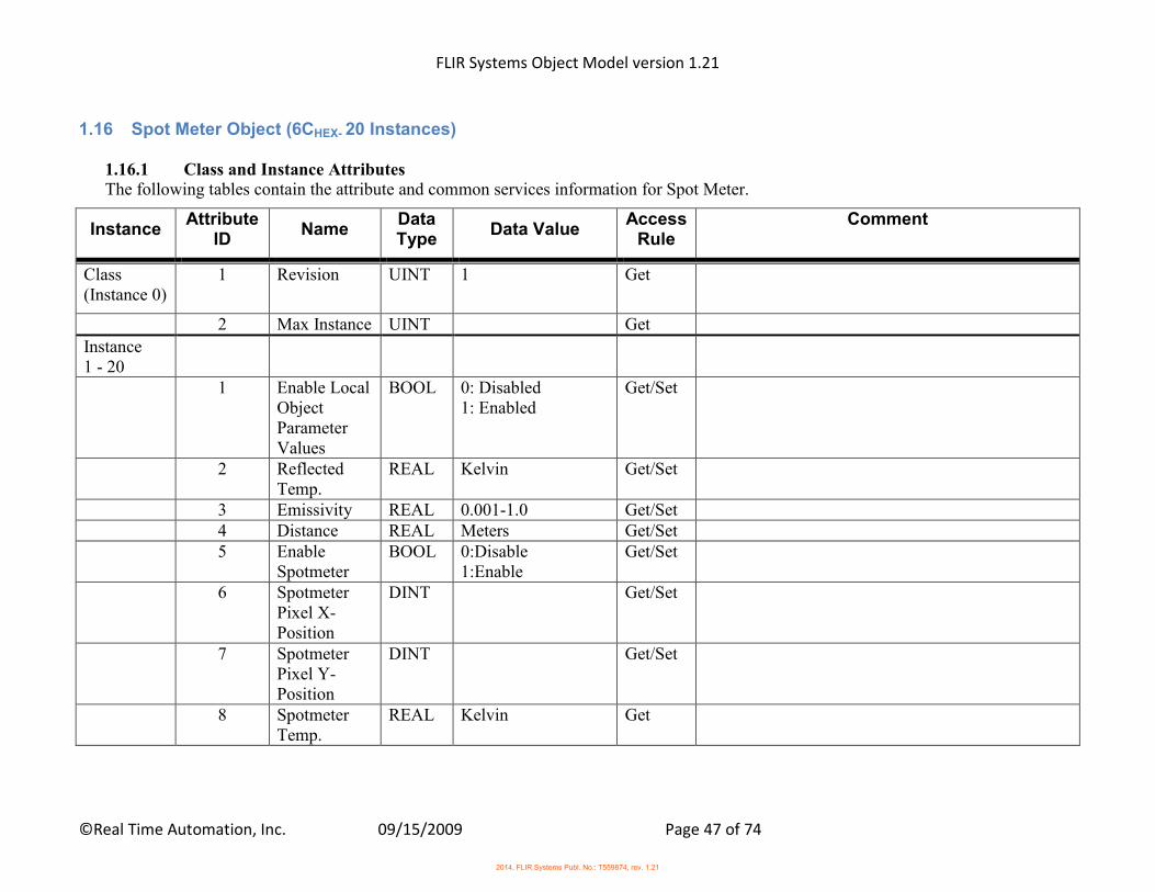
FLIR Systems Object Model version 1.21
©Real Time Automation, Inc. 09/15/2009 Page 47 of 74
1.16 Spot Meter Object (6CHEX- 20 Instances)
1.16.1 Class and Instance Attributes The following tables contain the attribute and common services information for Spot Meter.
Instance Attribute
ID Name
Data Type
Data Value Access
Rule Comment
Class (Instance 0)
1 Revision UINT 1 Get
2 Max Instance UINT Get
Instance 1 - 20
1 Enable Local Object Parameter Values
BOOL 0: Disabled 1: Enabled
Get/Set
2 Reflected Temp.
REAL Kelvin Get/Set
3 Emissivity REAL 0.001-1.0 Get/Set 4 Distance REAL Meters Get/Set 5 Enable
Spotmeter BOOL 0:Disable
1:Enable Get/Set
6 Spotmeter Pixel X-Position
DINT Get/Set
7 Spotmeter Pixel Y-Position
DINT Get/Set
8 Spotmeter Temp.
REAL Kelvin Get
2014, FLIR Systems Publ. No.: T559874, rev. 1.21
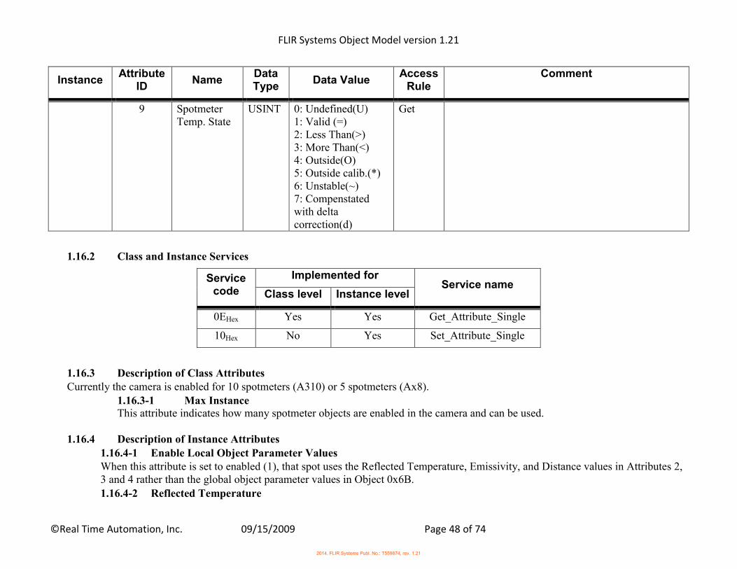
FLIR Systems Object Model version 1.21
©Real Time Automation, Inc. 09/15/2009 Page 48 of 74
Instance Attribute
ID Name
Data Type
Data Value Access
Rule Comment
9 Spotmeter Temp. State
USINT 0: Undefined(U) 1: Valid (=) 2: Less Than(>) 3: More Than(<) 4: Outside(O) 5: Outside calib.(*) 6: Unstable(~) 7: Compenstated with delta correction(d)
Get
1.16.2 Class and Instance Services
Service code
Implemented for Service name
Class level Instance level
0EHex Yes Yes Get_Attribute_Single
10Hex No Yes Set_Attribute_Single
1.16.3 Description of Class Attributes Currently the camera is enabled for 10 spotmeters (A310) or 5 spotmeters (Ax8).
1.16.3-1 Max Instance This attribute indicates how many spotmeter objects are enabled in the camera and can be used.
1.16.4 Description of Instance Attributes
1.16.4-1 Enable Local Object Parameter Values When this attribute is set to enabled (1), that spot uses the Reflected Temperature, Emissivity, and Distance values in Attributes 2, 3 and 4 rather than the global object parameter values in Object 0x6B. 1.16.4-2 Reflected Temperature
2014, FLIR Systems Publ. No.: T559874, rev. 1.21
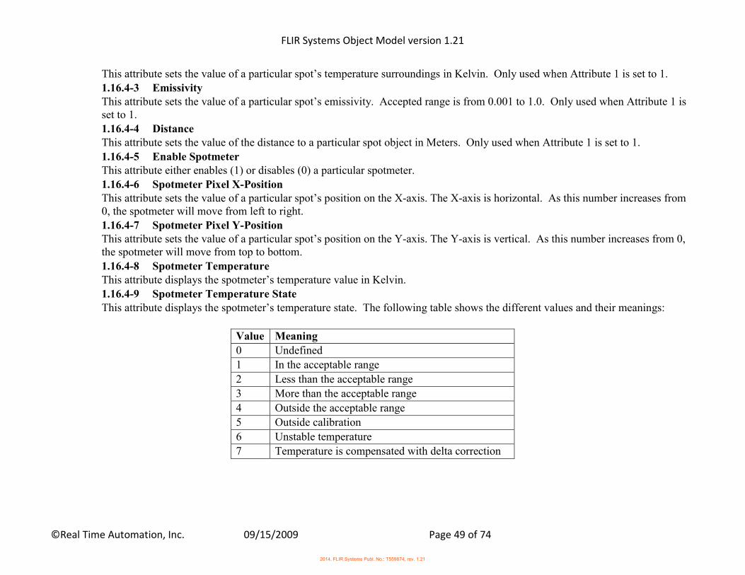
FLIR Systems Object Model version 1.21
©Real Time Automation, Inc. 09/15/2009 Page 49 of 74
This attribute sets the value of a particular spot’s temperature surroundings in Kelvin. Only used when Attribute 1 is set to 1. 1.16.4-3 Emissivity This attribute sets the value of a particular spot’s emissivity. Accepted range is from 0.001 to 1.0. Only used when Attribute 1 is set to 1. 1.16.4-4 Distance This attribute sets the value of the distance to a particular spot object in Meters. Only used when Attribute 1 is set to 1.
1.16.4-5 Enable Spotmeter This attribute either enables (1) or disables (0) a particular spotmeter. 1.16.4-6 Spotmeter Pixel X-Position This attribute sets the value of a particular spot’s position on the X-axis. The X-axis is horizontal. As this number increases from 0, the spotmeter will move from left to right. 1.16.4-7 Spotmeter Pixel Y-Position This attribute sets the value of a particular spot’s position on the Y-axis. The Y-axis is vertical. As this number increases from 0, the spotmeter will move from top to bottom.
1.16.4-8 Spotmeter Temperature This attribute displays the spotmeter’s temperature value in Kelvin. 1.16.4-9 Spotmeter Temperature State This attribute displays the spotmeter’s temperature state. The following table shows the different values and their meanings:
Value Meaning
0 Undefined
1 In the acceptable range
2 Less than the acceptable range
3 More than the acceptable range
4 Outside the acceptable range
5 Outside calibration
6 Unstable temperature
7 Temperature is compensated with delta correction
2014, FLIR Systems Publ. No.: T559874, rev. 1.21
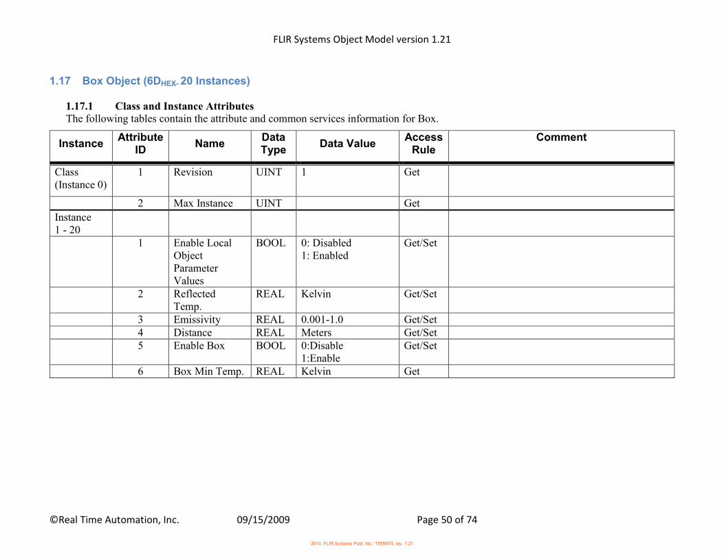
FLIR Systems Object Model version 1.21
©Real Time Automation, Inc. 09/15/2009 Page 50 of 74
1.17 Box Object (6DHEX- 20 Instances)
1.17.1 Class and Instance Attributes The following tables contain the attribute and common services information for Box.
Instance Attribute
ID Name
Data Type
Data Value Access
Rule Comment
Class (Instance 0)
1 Revision UINT 1 Get
2 Max Instance UINT Get
Instance 1 - 20
1 Enable Local Object Parameter Values
BOOL 0: Disabled 1: Enabled
Get/Set
2 Reflected Temp.
REAL Kelvin Get/Set
3 Emissivity REAL 0.001-1.0 Get/Set 4 Distance REAL Meters Get/Set 5 Enable Box BOOL 0:Disable
1:Enable Get/Set
6 Box Min Temp. REAL Kelvin Get
2014, FLIR Systems Publ. No.: T559874, rev. 1.21

FLIR Systems Object Model version 1.21
©Real Time Automation, Inc. 09/15/2009 Page 51 of 74
Instance Attribute
ID Name
Data Type
Data Value Access
Rule Comment
7 Box Min Temp. State
USINT 0: Undefined(U) 1: Valid (=) 2: Less Than(>) 3: More Than(<) 4: Outside(O) 5: Outside calib.(*) 6: Unstable(~) 7: Compenstated with delta correction(d)
Get
8 Box Max Temp. REAL Kelvin Get 9 Box Max Temp.
State USINT 0: Undefined(U)
1: Valid (=) 2: Less Than(>) 3: More Than(<) 4: Outside(O) 5: Outside calib.(*) 6: Unstable(~) 7: Compenstated with delta correction(d)
Get
10 Box Avg. Temp.
REAL Kelvin Get
2014, FLIR Systems Publ. No.: T559874, rev. 1.21
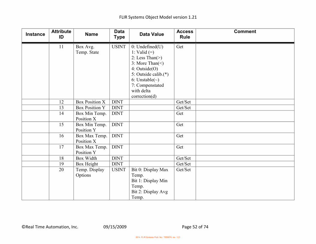
FLIR Systems Object Model version 1.21
©Real Time Automation, Inc. 09/15/2009 Page 52 of 74
Instance Attribute
ID Name
Data Type
Data Value Access
Rule Comment
11 Box Avg. Temp. State
USINT 0: Undefined(U) 1: Valid (=) 2: Less Than(>) 3: More Than(<) 4: Outside(O) 5: Outside calib.(*) 6: Unstable(~) 7: Compenstated with delta correction(d)
Get
12 Box Position X DINT Get/Set 13 Box Position Y DINT Get/Set 14 Box Min Temp.
Position X DINT Get
15 Box Min Temp. Position Y
DINT Get
16 Box Max Temp. Position X
DINT Get
17 Box Max Temp. Position Y
DINT Get
18 Box Width DINT Get/Set 19 Box Height DINT Get/Set 20 Temp. Display
Options USINT Bit 0: Display Max
Temp. Bit 1: Display Min Temp. Bit 2: Display Avg Temp.
Get/Set
2014, FLIR Systems Publ. No.: T559874, rev. 1.21
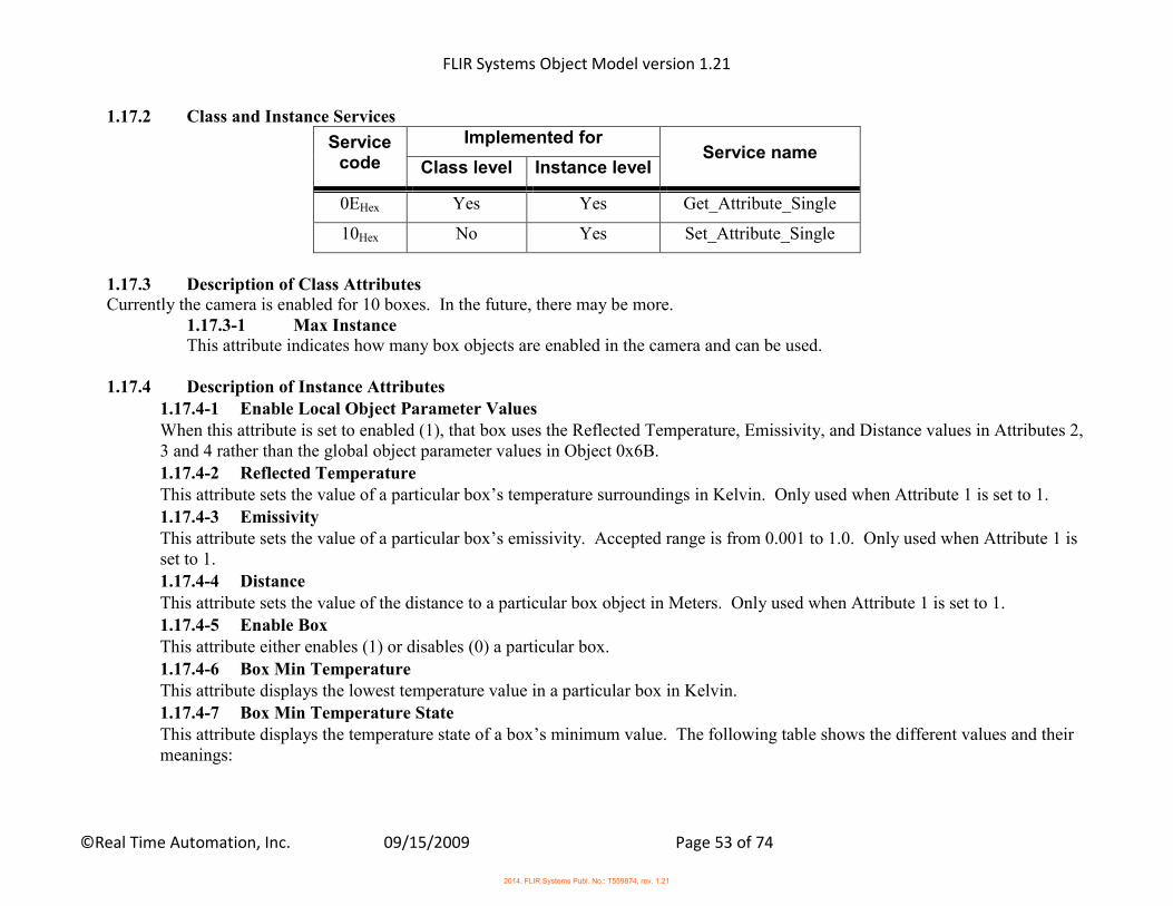
FLIR Systems Object Model version 1.21
©Real Time Automation, Inc. 09/15/2009 Page 53 of 74
1.17.2 Class and Instance Services
Service code
Implemented for Service name
Class level Instance level
0EHex Yes Yes Get_Attribute_Single
10Hex No Yes Set_Attribute_Single
1.17.3 Description of Class Attributes Currently the camera is enabled for 10 boxes. In the future, there may be more.
1.17.3-1 Max Instance This attribute indicates how many box objects are enabled in the camera and can be used.
1.17.4 Description of Instance Attributes
1.17.4-1 Enable Local Object Parameter Values When this attribute is set to enabled (1), that box uses the Reflected Temperature, Emissivity, and Distance values in Attributes 2, 3 and 4 rather than the global object parameter values in Object 0x6B. 1.17.4-2 Reflected Temperature This attribute sets the value of a particular box’s temperature surroundings in Kelvin. Only used when Attribute 1 is set to 1.
1.17.4-3 Emissivity This attribute sets the value of a particular box’s emissivity. Accepted range is from 0.001 to 1.0. Only used when Attribute 1 is set to 1. 1.17.4-4 Distance This attribute sets the value of the distance to a particular box object in Meters. Only used when Attribute 1 is set to 1. 1.17.4-5 Enable Box This attribute either enables (1) or disables (0) a particular box.
1.17.4-6 Box Min Temperature This attribute displays the lowest temperature value in a particular box in Kelvin. 1.17.4-7 Box Min Temperature State This attribute displays the temperature state of a box’s minimum value. The following table shows the different values and their meanings:
2014, FLIR Systems Publ. No.: T559874, rev. 1.21
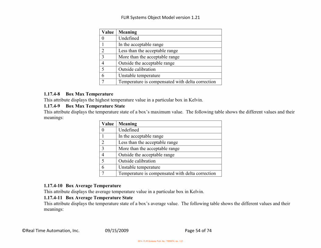
FLIR Systems Object Model version 1.21
©Real Time Automation, Inc. 09/15/2009 Page 54 of 74
Value Meaning
0 Undefined
1 In the acceptable range
2 Less than the acceptable range
3 More than the acceptable range
4 Outside the acceptable range
5 Outside calibration
6 Unstable temperature
7 Temperature is compensated with delta correction
1.17.4-8 Box Max Temperature This attribute displays the highest temperature value in a particular box in Kelvin.
1.17.4-9 Box Max Temperature State This attribute displays the temperature state of a box’s maximum value. The following table shows the different values and their meanings:
Value Meaning
0 Undefined
1 In the acceptable range
2 Less than the acceptable range
3 More than the acceptable range
4 Outside the acceptable range
5 Outside calibration
6 Unstable temperature
7 Temperature is compensated with delta correction
1.17.4-10 Box Average Temperature This attribute displays the average temperature value in a particular box in Kelvin.
1.17.4-11 Box Average Temperature State This attribute displays the temperature state of a box’s average value. The following table shows the different values and their meanings:
2014, FLIR Systems Publ. No.: T559874, rev. 1.21
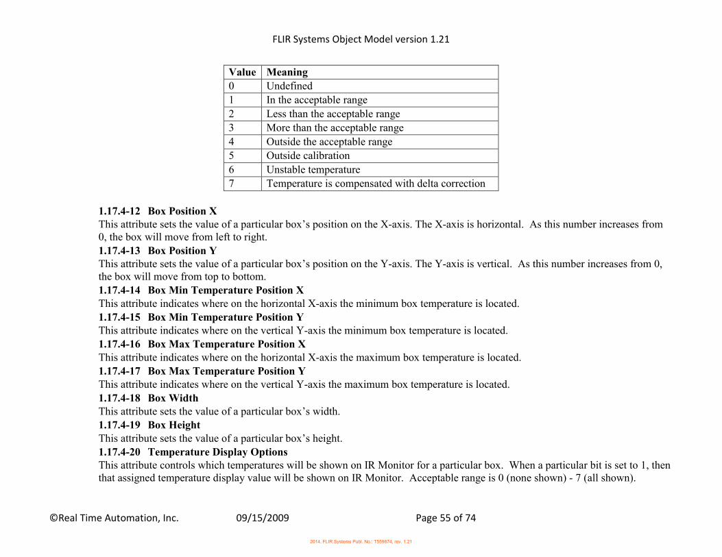
FLIR Systems Object Model version 1.21
©Real Time Automation, Inc. 09/15/2009 Page 55 of 74
Value Meaning
0 Undefined
1 In the acceptable range
2 Less than the acceptable range
3 More than the acceptable range
4 Outside the acceptable range
5 Outside calibration
6 Unstable temperature
7 Temperature is compensated with delta correction
1.17.4-12 Box Position X This attribute sets the value of a particular box’s position on the X-axis. The X-axis is horizontal. As this number increases from 0, the box will move from left to right.
1.17.4-13 Box Position Y This attribute sets the value of a particular box’s position on the Y-axis. The Y-axis is vertical. As this number increases from 0, the box will move from top to bottom. 1.17.4-14 Box Min Temperature Position X This attribute indicates where on the horizontal X-axis the minimum box temperature is located. 1.17.4-15 Box Min Temperature Position Y This attribute indicates where on the vertical Y-axis the minimum box temperature is located. 1.17.4-16 Box Max Temperature Position X This attribute indicates where on the horizontal X-axis the maximum box temperature is located. 1.17.4-17 Box Max Temperature Position Y This attribute indicates where on the vertical Y-axis the maximum box temperature is located.
1.17.4-18 Box Width This attribute sets the value of a particular box’s width. 1.17.4-19 Box Height This attribute sets the value of a particular box’s height. 1.17.4-20 Temperature Display Options This attribute controls which temperatures will be shown on IR Monitor for a particular box. When a particular bit is set to 1, then that assigned temperature display value will be shown on IR Monitor. Acceptable range is 0 (none shown) - 7 (all shown).
2014, FLIR Systems Publ. No.: T559874, rev. 1.21
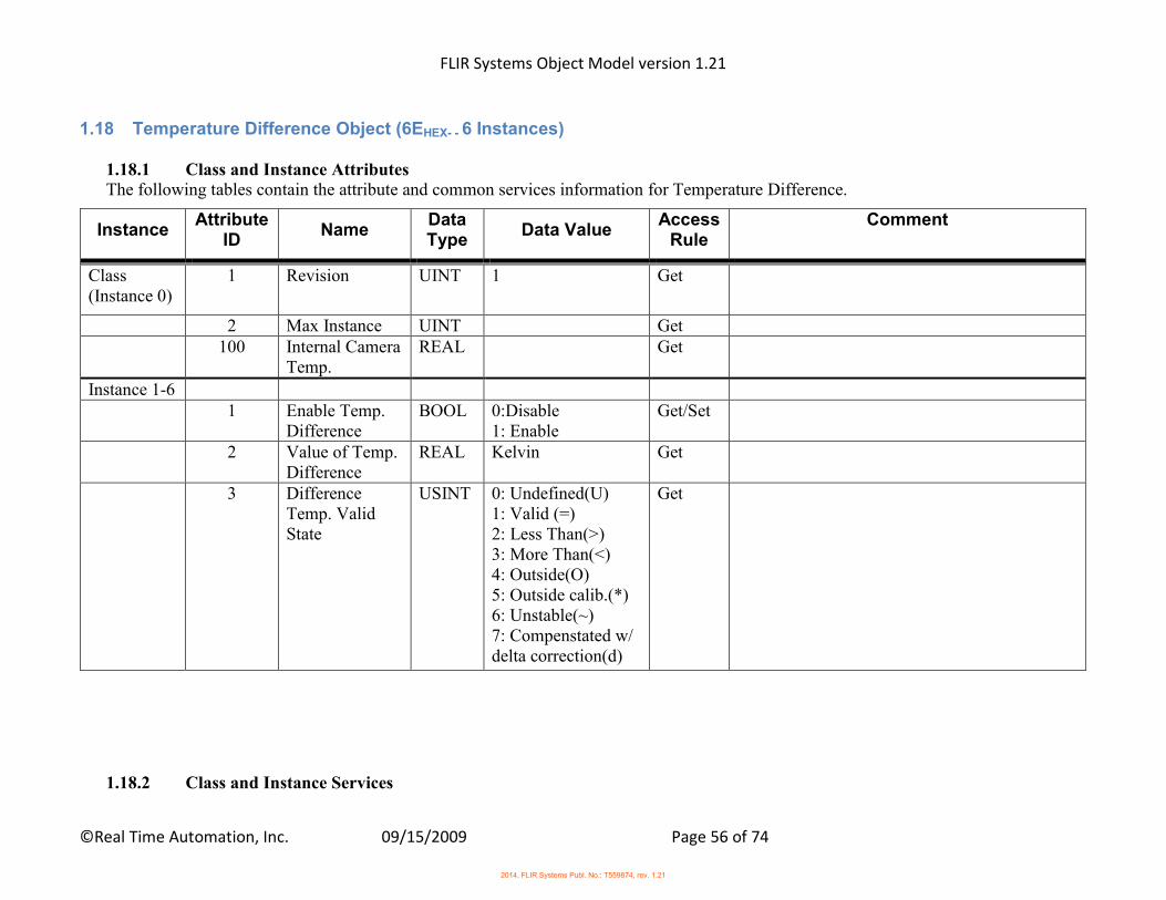
FLIR Systems Object Model version 1.21
©Real Time Automation, Inc. 09/15/2009 Page 56 of 74
1.18 Temperature Difference Object (6EHEX- - 6 Instances)
1.18.1 Class and Instance Attributes The following tables contain the attribute and common services information for Temperature Difference.
Instance Attribute
ID Name
Data Type
Data Value Access
Rule Comment
Class (Instance 0)
1 Revision UINT 1 Get
2 Max Instance UINT Get 100 Internal Camera
Temp. REAL Get
Instance 1-6 1 Enable Temp.
Difference BOOL 0:Disable
1: Enable Get/Set
2 Value of Temp. Difference
REAL Kelvin Get
3 Difference Temp. Valid State
USINT 0: Undefined(U) 1: Valid (=) 2: Less Than(>) 3: More Than(<) 4: Outside(O) 5: Outside calib.(*) 6: Unstable(~) 7: Compenstated w/ delta correction(d)
Get
1.18.2 Class and Instance Services
2014, FLIR Systems Publ. No.: T559874, rev. 1.21
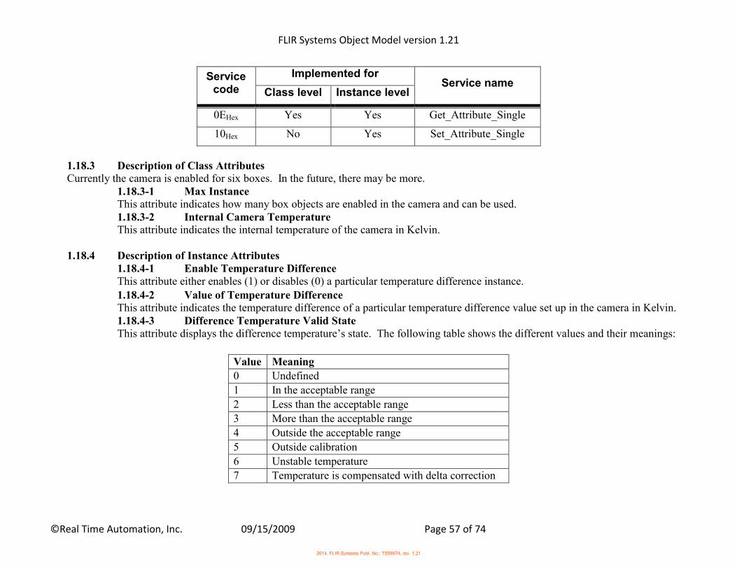
FLIR Systems Object Model version 1.21
©Real Time Automation, Inc. 09/15/2009 Page 57 of 74
Service code
Implemented for Service name
Class level Instance level
0EHex Yes Yes Get_Attribute_Single
10Hex No Yes Set_Attribute_Single
1.18.3 Description of Class Attributes Currently the camera is enabled for six boxes. In the future, there may be more.
1.18.3-1 Max Instance This attribute indicates how many box objects are enabled in the camera and can be used. 1.18.3-2 Internal Camera Temperature This attribute indicates the internal temperature of the camera in Kelvin.
1.18.4 Description of Instance Attributes 1.18.4-1 Enable Temperature Difference This attribute either enables (1) or disables (0) a particular temperature difference instance. 1.18.4-2 Value of Temperature Difference This attribute indicates the temperature difference of a particular temperature difference value set up in the camera in Kelvin. 1.18.4-3 Difference Temperature Valid State This attribute displays the difference temperature’s state. The following table shows the different values and their meanings:
Value Meaning
0 Undefined
1 In the acceptable range
2 Less than the acceptable range
3 More than the acceptable range
4 Outside the acceptable range
5 Outside calibration
6 Unstable temperature
7 Temperature is compensated with delta correction
2014, FLIR Systems Publ. No.: T559874, rev. 1.21

FLIR Systems Object Model version 1.21
©Real Time Automation, Inc. 09/15/2009 Page 58 of 74
1.19 Physical I/O Object (6FHEX- - 1 Instance)
1.19.1 Class and Instance Attributes The following tables contain the attribute and common services information for Temperature Difference.
Instance Attribute
ID Name Data Type Data Value
Access Rule
Comment
Class (Instance 0)
1 Revision UINT 1 Get
Instance 1 1 DI 1 BOOL 0:Off
1:On Get
2 DI 2 BOOL 0:Off 1:On
Get N/A for FLIR Ax8
101 DO 1 BOOL 0:Low 1:High
Get/Set
102 DO 2 BOOL 0:Low 1:High
Get/Set N/A for FLIR Ax8
1.19.2 Class and Instance Services
Service code
Implemented for Service name
Class level Instance level
0EHex Yes Yes Get_Attribute_Single
10Hex No Yes Set_Attribute_Single
1.19.3 Description of Instance Attributes
1.19.3-1 DI 1 This attribute indicates if Digital Input 1 is active (1) or inactive (0).
1.19.3-2 DI 2
2014, FLIR Systems Publ. No.: T559874, rev. 1.21
FLIR Systems Object Model version 1.21
©Real Time Automation, Inc. 09/15/2009 Page 59 of 74
This attribute indicates if Digital Input 2 is active (1) or inactive (0). 1.19.3-3 DO 1 This attribute either sets the Digital Output 1 to an active (1) or inactive (0) state. 1.19.3-4 DO 2 This attribute either sets the Digital Output 2 to an active (1) or inactive (0) state.
2014, FLIR Systems Publ. No.: T559874, rev. 1.21
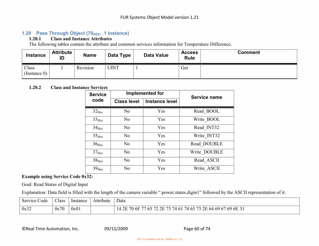
FLIR Systems Object Model version 1.21
©Real Time Automation, Inc. 09/15/2009 Page 60 of 74
1.20 Pass Through Object (70HEX- - 1 Instance) 1.20.1 Class and Instance Attributes The following tables contain the attribute and common services information for Temperature Difference.
Instance Attribute
ID Name Data Type Data Value
Access Rule
Comment
Class (Instance 0)
1 Revision UINT 1 Get
1.20.2 Class and Instance Services
Service code
Implemented for Service name
Class level Instance level
32Hex No Yes Read_BOOL
33Hex No Yes Write_BOOL
34Hex No Yes Read_INT32
35Hex No Yes Write_INT32
36Hex No Yes Read_DOUBLE
37Hex No Yes Write_DOUBLE
38Hex No Yes Read_ASCII
39Hex No Yes Write_ASCII
Example using Service Code 0x32:
Goal: Read Status of Digital Input
Explanation: Data field is filled with the length of the camera variable “.power.states.digin1” followed by the ASCII representation of it.
Service Code Class Instance Attribute Data
0x32 0x70 0x01 14 2E 70 6F 77 65 72 2E 73 74 61 74 65 73 2E 64 69 67 69 6E 31
2014, FLIR Systems Publ. No.: T559874, rev. 1.21
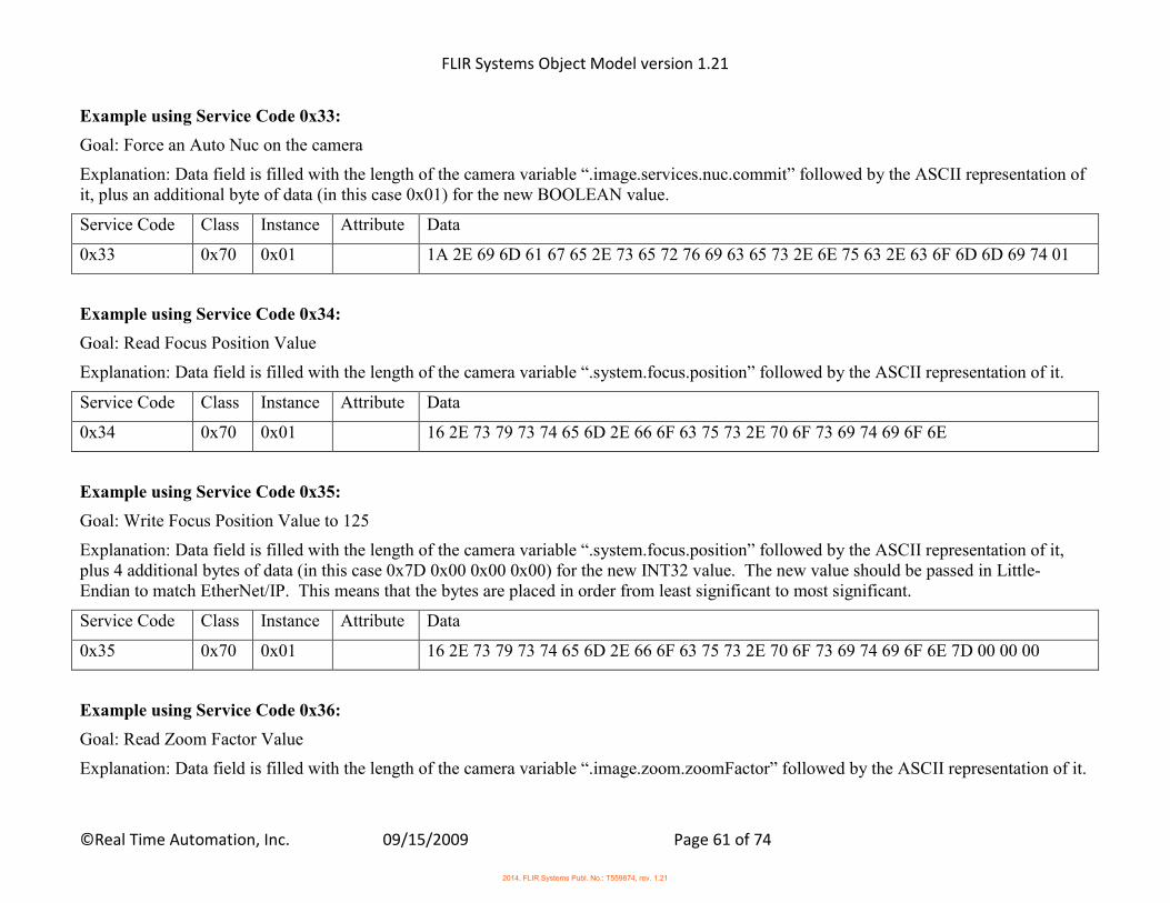
FLIR Systems Object Model version 1.21
©Real Time Automation, Inc. 09/15/2009 Page 61 of 74
Example using Service Code 0x33:
Goal: Force an Auto Nuc on the camera
Explanation: Data field is filled with the length of the camera variable “.image.services.nuc.commit” followed by the ASCII representation of it, plus an additional byte of data (in this case 0x01) for the new BOOLEAN value.
Service Code Class Instance Attribute Data
0x33 0x70 0x01 1A 2E 69 6D 61 67 65 2E 73 65 72 76 69 63 65 73 2E 6E 75 63 2E 63 6F 6D 6D 69 74 01
Example using Service Code 0x34:
Goal: Read Focus Position Value
Explanation: Data field is filled with the length of the camera variable “.system.focus.position” followed by the ASCII representation of it.
Service Code Class Instance Attribute Data
0x34 0x70 0x01 16 2E 73 79 73 74 65 6D 2E 66 6F 63 75 73 2E 70 6F 73 69 74 69 6F 6E
Example using Service Code 0x35:
Goal: Write Focus Position Value to 125
Explanation: Data field is filled with the length of the camera variable “.system.focus.position” followed by the ASCII representation of it, plus 4 additional bytes of data (in this case 0x7D 0x00 0x00 0x00) for the new INT32 value. The new value should be passed in Little-Endian to match EtherNet/IP. This means that the bytes are placed in order from least significant to most significant.
Service Code Class Instance Attribute Data
0x35 0x70 0x01 16 2E 73 79 73 74 65 6D 2E 66 6F 63 75 73 2E 70 6F 73 69 74 69 6F 6E 7D 00 00 00
Example using Service Code 0x36:
Goal: Read Zoom Factor Value
Explanation: Data field is filled with the length of the camera variable “.image.zoom.zoomFactor” followed by the ASCII representation of it.
2014, FLIR Systems Publ. No.: T559874, rev. 1.21

FLIR Systems Object Model version 1.21
©Real Time Automation, Inc. 09/15/2009 Page 62 of 74
Service Code Class Instance Attribute Data
0x36 0x70 0x01 16 2E 69 6D 61 67 65 2E 7A 6F 6F 6D 2E 7A 6F 6F 6D 46 61 63 74 6F 72
Example using Service Code 0x37:
Goal: Write Focus Position Value to 8.0
Explanation: Data field is filled with the length of the camera variable “.image.zoom.zoomFactor” followed by the ASCII representation of it, plus 4 additional bytes of data (in this case 0x00 0x00 0x00 0x41) for the new REAL value. The new value should be passed in Little-Endian to match EtherNet/IP. This means that the bytes are placed in order from least significant to most significant.
Service Code Class Instance Attribute Data
0x37 0x70 0x01 16 2E 69 6D 61 67 65 2E 7A 6F 6F 6D 2E 7A 6F 6F 6D 46 61 63 74 6F 72 00 00 00 41
Example using Service Code 0x38:
Goal: Read Image Automatic Adjust Setting
Explanation: Data field is filled with the length of the camera variable “.image.contadj.adjMode” followed by the ASCII representation of it.
Service Code Class Instance Attribute Data
0x38 0x70 0x01 16 2E 69 6D 61 67 65 2E 63 6F 6E 74 61 64 6A 2E 61 64 6A 4D 6F 64 65
Example using Service Code 0x39:
Goal: Write Image Automatic Adjust Setting to “Auto”
Explanation: Data field is filled with the length of the camera variable “.image.contadj.adjMode” followed by the ASCII representation of it. The next byte of data is the size of the new ASCII string value to follow (in this case 0x04). Then, attach the new ASCII value (in this case “0x41 0x75 0x74 0x6F”).
Service Code Class Instance Attribute Data
0x39 0x70 0x01 16 2E 69 6D 61 67 65 2E 63 6F 6E 74 61 64 6A 2E 61 64 6A 4D 6F 64 65 04 41 75 74 6F
2014, FLIR Systems Publ. No.: T559874, rev. 1.21
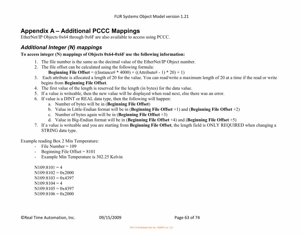
FLIR Systems Object Model version 1.21
©Real Time Automation, Inc. 09/15/2009 Page 63 of 74
Appendix A – Additional PCCC Mappings EtherNet/IP Objects 0x64 through 0x6F are also available to access using PCCC.
Additional Integer (N) mappings To access integer (N) mappings of Objects 0x64-0x6F use the following information:
1. The file number is the same as the decimal value of the EtherNet/IP Object number. 2. The file offset can be calculated using the following formula:
Beginning File Offset = ((Instance# * 4000) + ((Attribute# - 1) * 20) + 1) 3. Each attribute is allocated a length of 20 for the value. You can read/write a maximum length of 20 at a time if the read or write
begins from Beginning File Offset. 4. The first value of the length is reserved for the length (in bytes) for the data value. 5. If a value is writeable, then the new value will be displayed when read next, else there was an error. 6. If value is a DINT or REAL data type, then the following will happen:
a. Number of bytes will be in (Beginning File Offset) b. Value in Little-Endian format will be in (Beginning File Offset +1) and (Beginning File Offset +2) c. Number of bytes again will be in (Beginning File Offset +3) d. Value in Big-Endian format will be in (Beginning File Offset +4) and (Beginning File Offset +5)
7. If a value is writeable and you are starting from Beginning File Offset, the length field is ONLY REQUIRED when changing a STRING data type.
Example reading Box 2 Min Temperature:
- File Number = 109 - Beginning File Offset = 8101 - Example Min Temperature is 302.25 Kelvin N109:8101 = 4 N109:8102 = 0x2000 N109:8103 = 0x4397 N109:8104 = 4 N109:8105 = 0x4397 N109:8106 = 0x2000
2014, FLIR Systems Publ. No.: T559874, rev. 1.21
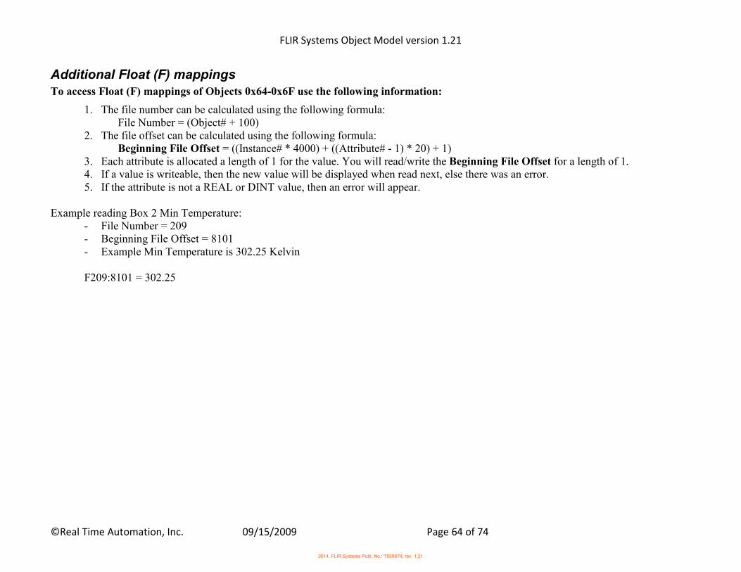
FLIR Systems Object Model version 1.21
©Real Time Automation, Inc. 09/15/2009 Page 64 of 74
Additional Float (F) mappings To access Float (F) mappings of Objects 0x64-0x6F use the following information:
1. The file number can be calculated using the following formula: File Number = (Object# + 100)
2. The file offset can be calculated using the following formula: Beginning File Offset = ((Instance# * 4000) + ((Attribute# - 1) * 20) + 1)
3. Each attribute is allocated a length of 1 for the value. You will read/write the Beginning File Offset for a length of 1. 4. If a value is writeable, then the new value will be displayed when read next, else there was an error. 5. If the attribute is not a REAL or DINT value, then an error will appear.
Example reading Box 2 Min Temperature:
- File Number = 209 - Beginning File Offset = 8101 - Example Min Temperature is 302.25 Kelvin F209:8101 = 302.25
2014, FLIR Systems Publ. No.: T559874, rev. 1.21
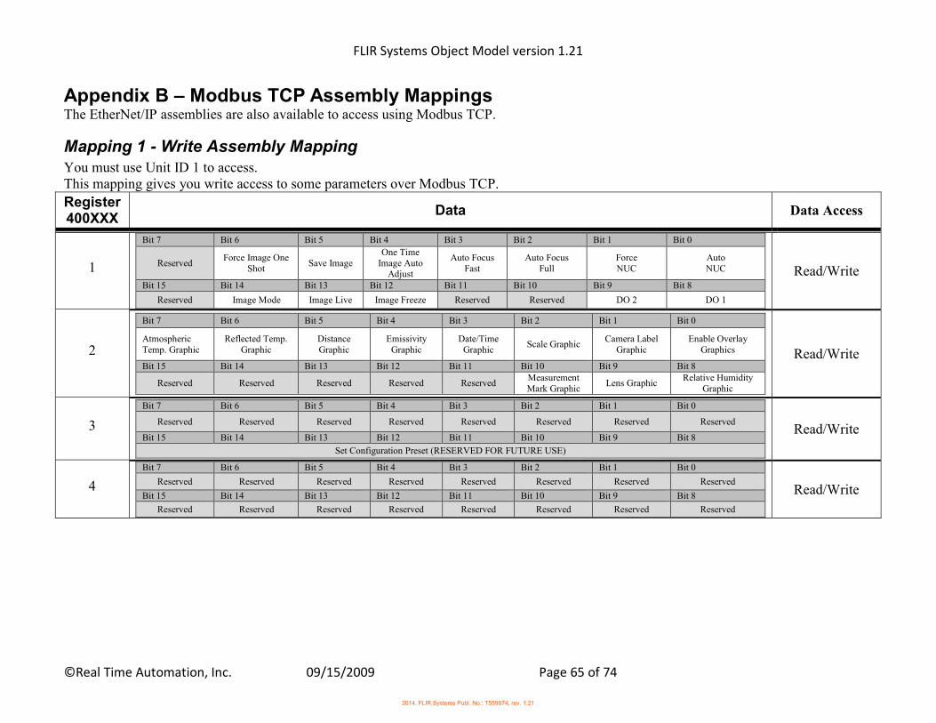
FLIR Systems Object Model version 1.21
©Real Time Automation, Inc. 09/15/2009 Page 65 of 74
Appendix B – Modbus TCP Assembly Mappings The EtherNet/IP assemblies are also available to access using Modbus TCP.
Mapping 1 - Write Assembly Mapping You must use Unit ID 1 to access. This mapping gives you write access to some parameters over Modbus TCP.
Register 400XXX
Data Data Access
1
Bit 7 Bit 6 Bit 5 Bit 4 Bit 3 Bit 2 Bit 1 Bit 0
Reserved Force Image One
Shot Save Image
One Time Image Auto
Adjust
Auto Focus Fast
Auto Focus Full
Force NUC
Auto NUC
Bit 15 Bit 14 Bit 13 Bit 12 Bit 11 Bit 10 Bit 9 Bit 8
Reserved Image Mode Image Live Image Freeze Reserved Reserved DO 2 DO 1
Read/Write
2
Bit 7 Bit 6 Bit 5 Bit 4 Bit 3 Bit 2 Bit 1 Bit 0
Atmospheric Temp. Graphic
Reflected Temp. Graphic
Distance Graphic
Emissivity Graphic
Date/Time Graphic
Scale Graphic Camera Label
Graphic Enable Overlay
Graphics
Bit 15 Bit 14 Bit 13 Bit 12 Bit 11 Bit 10 Bit 9 Bit 8
Reserved Reserved Reserved Reserved Reserved Measurement Mark Graphic
Lens Graphic Relative Humidity
Graphic
Read/Write
3
Bit 7 Bit 6 Bit 5 Bit 4 Bit 3 Bit 2 Bit 1 Bit 0
Reserved Reserved Reserved Reserved Reserved Reserved Reserved Reserved
Bit 15 Bit 14 Bit 13 Bit 12 Bit 11 Bit 10 Bit 9 Bit 8
Set Configuration Preset (RESERVED FOR FUTURE USE)
Read/Write
4
Bit 7 Bit 6 Bit 5 Bit 4 Bit 3 Bit 2 Bit 1 Bit 0
Reserved Reserved Reserved Reserved Reserved Reserved Reserved Reserved
Bit 15 Bit 14 Bit 13 Bit 12 Bit 11 Bit 10 Bit 9 Bit 8
Reserved Reserved Reserved Reserved Reserved Reserved Reserved Reserved
Read/Write
2014, FLIR Systems Publ. No.: T559874, rev. 1.21
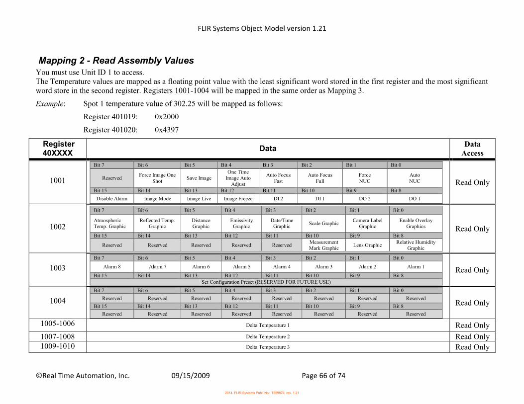
FLIR Systems Object Model version 1.21
©Real Time Automation, Inc. 09/15/2009 Page 66 of 74
Mapping 2 - Read Assembly Values You must use Unit ID 1 to access. The Temperature values are mapped as a floating point value with the least significant word stored in the first register and the most significant word store in the second register. Registers 1001-1004 will be mapped in the same order as Mapping 3.
Example: Spot 1 temperature value of 302.25 will be mapped as follows:
Register 401019: 0x2000
Register 401020: 0x4397
Register 40XXXX
Data Data
Access
1001
Bit 7 Bit 6 Bit 5 Bit 4 Bit 3 Bit 2 Bit 1 Bit 0
Reserved Force Image One
Shot Save Image
One Time Image Auto
Adjust
Auto Focus Fast
Auto Focus Full
Force NUC
Auto NUC
Bit 15 Bit 14 Bit 13 Bit 12 Bit 11 Bit 10 Bit 9 Bit 8
Disable Alarm Image Mode Image Live Image Freeze DI 2 DI 1 DO 2 DO 1
Read Only
1002
Bit 7 Bit 6 Bit 5 Bit 4 Bit 3 Bit 2 Bit 1 Bit 0
Atmospheric Temp. Graphic
Reflected Temp. Graphic
Distance Graphic
Emissivity Graphic
Date/Time Graphic
Scale Graphic Camera Label
Graphic Enable Overlay
Graphics
Bit 15 Bit 14 Bit 13 Bit 12 Bit 11 Bit 10 Bit 9 Bit 8
Reserved Reserved Reserved Reserved Reserved Measurement Mark Graphic
Lens Graphic Relative Humidity
Graphic
Read Only
1003
Bit 7 Bit 6 Bit 5 Bit 4 Bit 3 Bit 2 Bit 1 Bit 0
Alarm 8 Alarm 7 Alarm 6 Alarm 5 Alarm 4 Alarm 3 Alarm 2 Alarm 1
Bit 15 Bit 14 Bit 13 Bit 12 Bit 11 Bit 10 Bit 9 Bit 8 Set Configuration Preset (RESERVED FOR FUTURE USE)
Read Only
1004
Bit 7 Bit 6 Bit 5 Bit 4 Bit 3 Bit 2 Bit 1 Bit 0
Reserved Reserved Reserved Reserved Reserved Reserved Reserved Reserved
Bit 15 Bit 14 Bit 13 Bit 12 Bit 11 Bit 10 Bit 9 Bit 8
Reserved Reserved Reserved Reserved Reserved Reserved Reserved Reserved
Read Only
1005-1006 Delta Temperature 1 Read Only
1007-1008 Delta Temperature 2 Read Only 1009-1010 Delta Temperature 3 Read Only
2014, FLIR Systems Publ. No.: T559874, rev. 1.21
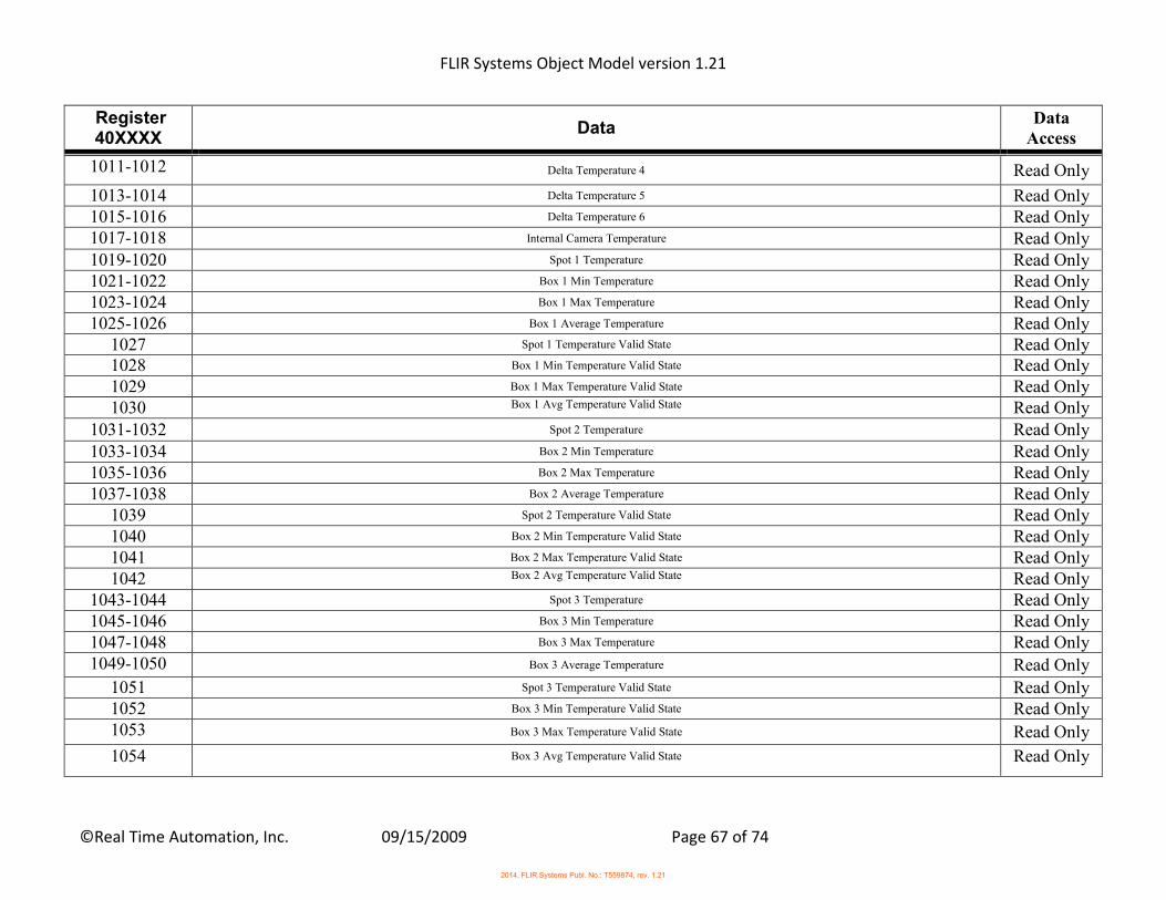
FLIR Systems Object Model version 1.21
©Real Time Automation, Inc. 09/15/2009 Page 67 of 74
Register 40XXXX
Data Data
Access
1011-1012 Delta Temperature 4 Read Only
1013-1014 Delta Temperature 5 Read Only 1015-1016 Delta Temperature 6 Read Only 1017-1018 Internal Camera Temperature Read Only 1019-1020 Spot 1 Temperature Read Only 1021-1022 Box 1 Min Temperature Read Only 1023-1024 Box 1 Max Temperature Read Only 1025-1026 Box 1 Average Temperature Read Only
1027 Spot 1 Temperature Valid State Read Only 1028 Box 1 Min Temperature Valid State Read Only 1029 Box 1 Max Temperature Valid State Read Only 1030 Box 1 Avg Temperature Valid State Read Only
1031-1032 Spot 2 Temperature Read Only 1033-1034 Box 2 Min Temperature Read Only 1035-1036 Box 2 Max Temperature Read Only 1037-1038 Box 2 Average Temperature Read Only
1039 Spot 2 Temperature Valid State Read Only 1040 Box 2 Min Temperature Valid State Read Only 1041 Box 2 Max Temperature Valid State Read Only 1042 Box 2 Avg Temperature Valid State Read Only
1043-1044 Spot 3 Temperature Read Only 1045-1046 Box 3 Min Temperature Read Only 1047-1048 Box 3 Max Temperature Read Only 1049-1050 Box 3 Average Temperature Read Only
1051 Spot 3 Temperature Valid State Read Only 1052 Box 3 Min Temperature Valid State Read Only 1053 Box 3 Max Temperature Valid State Read Only
1054 Box 3 Avg Temperature Valid State Read Only
2014, FLIR Systems Publ. No.: T559874, rev. 1.21
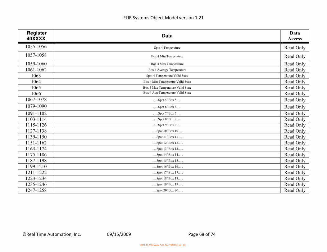
FLIR Systems Object Model version 1.21
©Real Time Automation, Inc. 09/15/2009 Page 68 of 74
Register 40XXXX
Data Data
Access
1055-1056 Spot 4 Temperature Read Only
1057-1058 Box 4 Min Temperature Read Only
1059-1060 Box 4 Max Temperature Read Only 1061-1062 Box 4 Average Temperature Read Only
1063 Spot 4 Temperature Valid State Read Only 1064 Box 4 Min Temperature Valid State Read Only 1065 Box 4 Max Temperature Valid State Read Only 1066 Box 4 Avg Temperature Valid State Read Only
1067-1078 …..Spot 5/ Box 5….. Read Only
1079-1090 …..Spot 6/ Box 6….. Read Only
1091-1102 …..Spot 7/ Box 7….. Read Only 1103-1114 …..Spot 8/ Box 8….. Read Only 1115-1126 …..Spot 9/ Box 9….. Read Only 1127-1138 …..Spot 10/ Box 10….. Read Only 1139-1150 …..Spot 11/ Box 11….. Read Only 1151-1162 …..Spot 12/ Box 12….. Read Only 1163-1174 …..Spot 13/ Box 13….. Read Only 1175-1186 …..Spot 14/ Box 14….. Read Only 1187-1198 …..Spot 15/ Box 15….. Read Only 1199-1210 …..Spot 16/ Box 16….. Read Only 1211-1222 …..Spot 17/ Box 17….. Read Only 1223-1234 …..Spot 18/ Box 18….. Read Only 1235-1246 …..Spot 19/ Box 19….. Read Only 1247-1258 …..Spot 20/ Box 20….. Read Only
2014, FLIR Systems Publ. No.: T559874, rev. 1.21
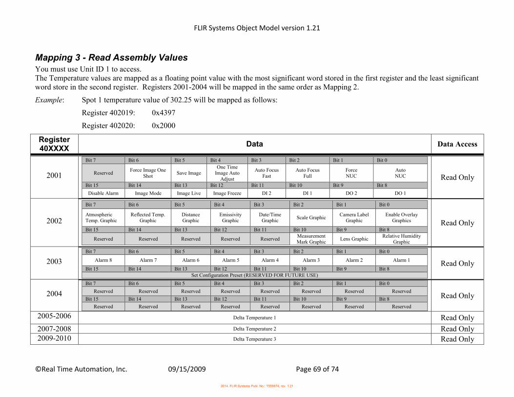
FLIR Systems Object Model version 1.21
©Real Time Automation, Inc. 09/15/2009 Page 69 of 74
Mapping 3 - Read Assembly Values You must use Unit ID 1 to access. The Temperature values are mapped as a floating point value with the most significant word stored in the first register and the least significant word store in the second register. Registers 2001-2004 will be mapped in the same order as Mapping 2.
Example: Spot 1 temperature value of 302.25 will be mapped as follows:
Register 402019: 0x4397
Register 402020: 0x2000
Register 40XXXX
Data Data Access
2001
Bit 7 Bit 6 Bit 5 Bit 4 Bit 3 Bit 2 Bit 1 Bit 0
Reserved Force Image One
Shot Save Image
One Time Image Auto
Adjust
Auto Focus Fast
Auto Focus Full
Force NUC
Auto NUC
Bit 15 Bit 14 Bit 13 Bit 12 Bit 11 Bit 10 Bit 9 Bit 8
Disable Alarm Image Mode Image Live Image Freeze DI 2 DI 1 DO 2 DO 1
Read Only
2002
Bit 7 Bit 6 Bit 5 Bit 4 Bit 3 Bit 2 Bit 1 Bit 0
Atmospheric Temp. Graphic
Reflected Temp. Graphic
Distance Graphic
Emissivity Graphic
Date/Time Graphic
Scale Graphic Camera Label
Graphic Enable Overlay
Graphics
Bit 15 Bit 14 Bit 13 Bit 12 Bit 11 Bit 10 Bit 9 Bit 8
Reserved Reserved Reserved Reserved Reserved Measurement Mark Graphic
Lens Graphic Relative Humidity
Graphic
Read Only
2003
Bit 7 Bit 6 Bit 5 Bit 4 Bit 3 Bit 2 Bit 1 Bit 0
Alarm 8 Alarm 7 Alarm 6 Alarm 5 Alarm 4 Alarm 3 Alarm 2 Alarm 1
Bit 15 Bit 14 Bit 13 Bit 12 Bit 11 Bit 10 Bit 9 Bit 8 Set Configuration Preset (RESERVED FOR FUTURE USE)
Read Only
2004
Bit 7 Bit 6 Bit 5 Bit 4 Bit 3 Bit 2 Bit 1 Bit 0
Reserved Reserved Reserved Reserved Reserved Reserved Reserved Reserved
Bit 15 Bit 14 Bit 13 Bit 12 Bit 11 Bit 10 Bit 9 Bit 8
Reserved Reserved Reserved Reserved Reserved Reserved Reserved Reserved
Read Only
2005-2006 Delta Temperature 1 Read Only
2007-2008 Delta Temperature 2 Read Only 2009-2010 Delta Temperature 3 Read Only
2014, FLIR Systems Publ. No.: T559874, rev. 1.21
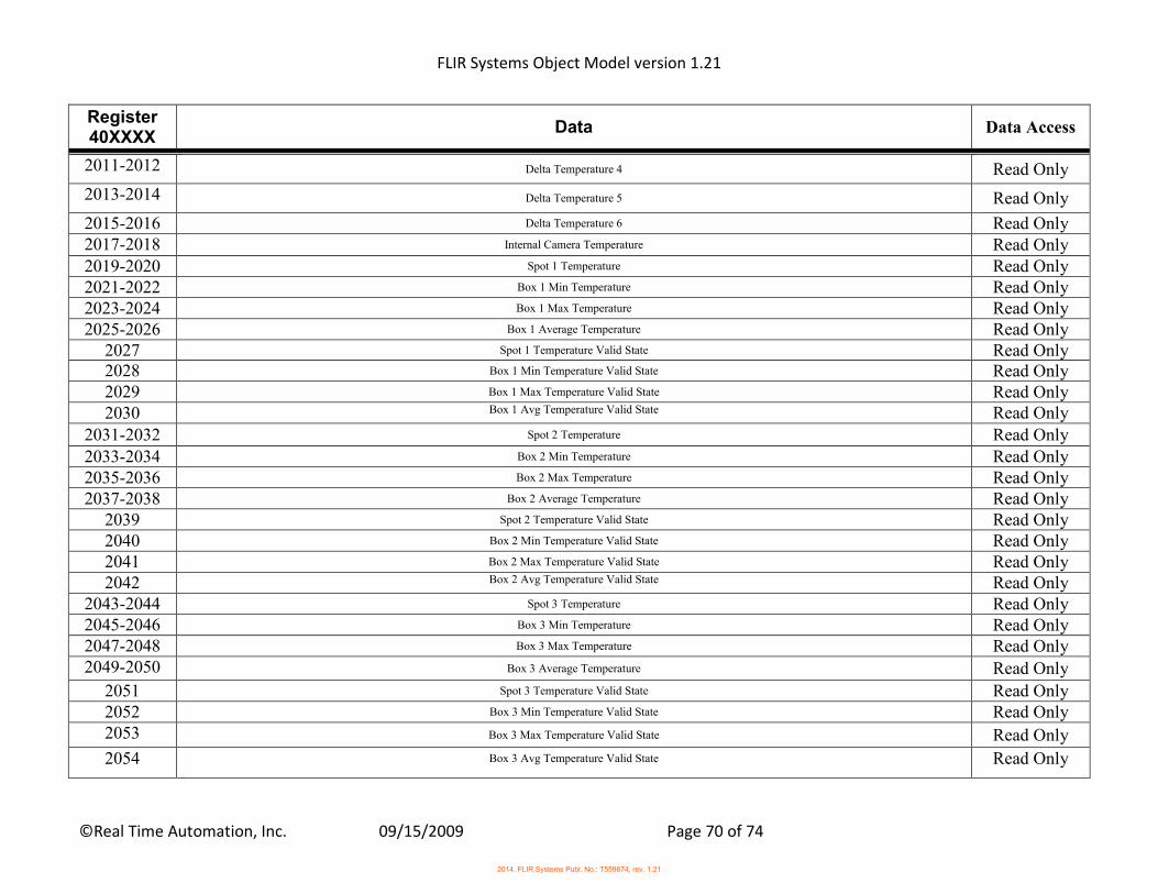
FLIR Systems Object Model version 1.21
©Real Time Automation, Inc. 09/15/2009 Page 70 of 74
Register 40XXXX
Data Data Access
2011-2012 Delta Temperature 4 Read Only
2013-2014 Delta Temperature 5 Read Only
2015-2016 Delta Temperature 6 Read Only 2017-2018 Internal Camera Temperature Read Only 2019-2020 Spot 1 Temperature Read Only 2021-2022 Box 1 Min Temperature Read Only 2023-2024 Box 1 Max Temperature Read Only 2025-2026 Box 1 Average Temperature Read Only
2027 Spot 1 Temperature Valid State Read Only 2028 Box 1 Min Temperature Valid State Read Only 2029 Box 1 Max Temperature Valid State Read Only 2030 Box 1 Avg Temperature Valid State Read Only
2031-2032 Spot 2 Temperature Read Only 2033-2034 Box 2 Min Temperature Read Only 2035-2036 Box 2 Max Temperature Read Only 2037-2038 Box 2 Average Temperature Read Only
2039 Spot 2 Temperature Valid State Read Only 2040 Box 2 Min Temperature Valid State Read Only 2041 Box 2 Max Temperature Valid State Read Only 2042 Box 2 Avg Temperature Valid State Read Only
2043-2044 Spot 3 Temperature Read Only 2045-2046 Box 3 Min Temperature Read Only 2047-2048 Box 3 Max Temperature Read Only 2049-2050 Box 3 Average Temperature Read Only
2051 Spot 3 Temperature Valid State Read Only 2052 Box 3 Min Temperature Valid State Read Only 2053 Box 3 Max Temperature Valid State Read Only
2054 Box 3 Avg Temperature Valid State Read Only
2014, FLIR Systems Publ. No.: T559874, rev. 1.21
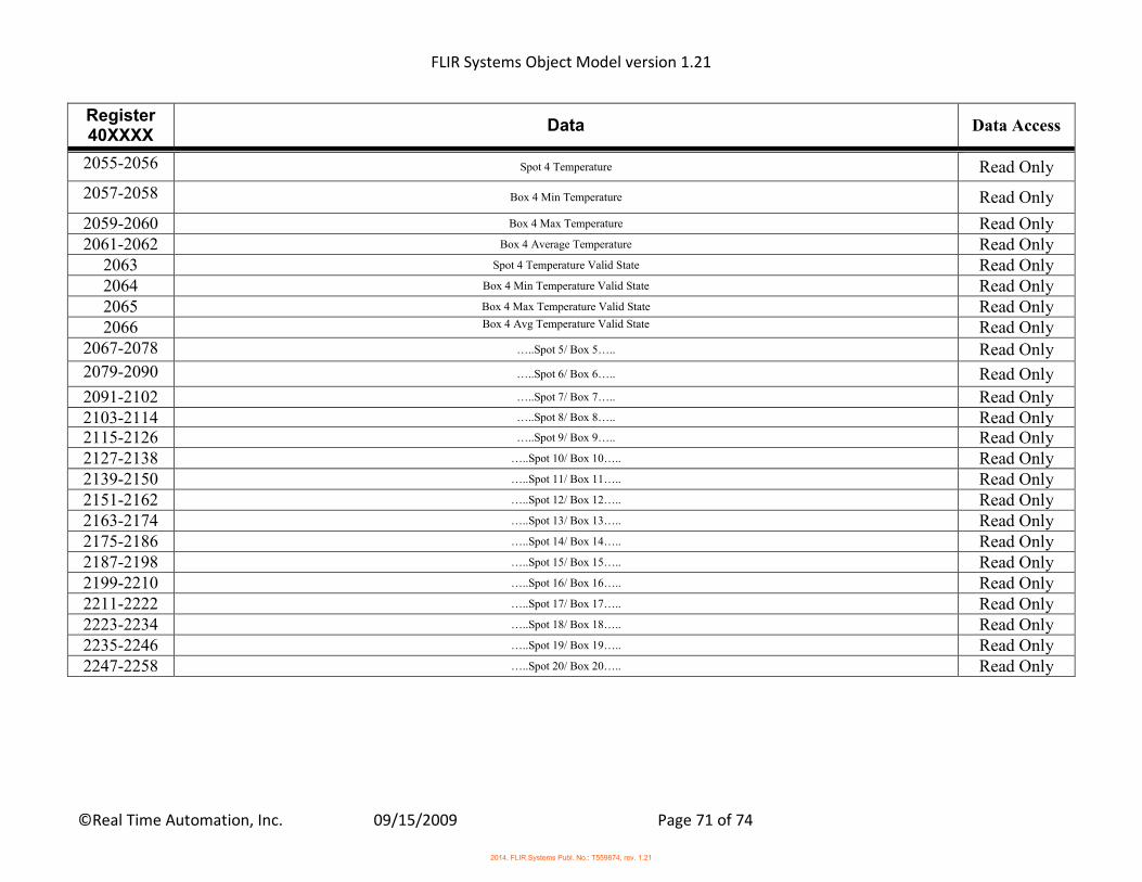
FLIR Systems Object Model version 1.21
©Real Time Automation, Inc. 09/15/2009 Page 71 of 74
Register 40XXXX
Data Data Access
2055-2056 Spot 4 Temperature Read Only
2057-2058 Box 4 Min Temperature Read Only
2059-2060 Box 4 Max Temperature Read Only 2061-2062 Box 4 Average Temperature Read Only
2063 Spot 4 Temperature Valid State Read Only 2064 Box 4 Min Temperature Valid State Read Only 2065 Box 4 Max Temperature Valid State Read Only 2066 Box 4 Avg Temperature Valid State Read Only
2067-2078 …..Spot 5/ Box 5….. Read Only
2079-2090 …..Spot 6/ Box 6….. Read Only
2091-2102 …..Spot 7/ Box 7….. Read Only 2103-2114 …..Spot 8/ Box 8….. Read Only 2115-2126 …..Spot 9/ Box 9….. Read Only 2127-2138 …..Spot 10/ Box 10….. Read Only 2139-2150 …..Spot 11/ Box 11….. Read Only 2151-2162 …..Spot 12/ Box 12….. Read Only 2163-2174 …..Spot 13/ Box 13….. Read Only 2175-2186 …..Spot 14/ Box 14….. Read Only 2187-2198 …..Spot 15/ Box 15….. Read Only 2199-2210 …..Spot 16/ Box 16….. Read Only 2211-2222 …..Spot 17/ Box 17….. Read Only 2223-2234 …..Spot 18/ Box 18….. Read Only 2235-2246 …..Spot 19/ Box 19….. Read Only 2247-2258 …..Spot 20/ Box 20….. Read Only
2014, FLIR Systems Publ. No.: T559874, rev. 1.21

FLIR Systems Object Model version 1.21
©Real Time Automation, Inc. 09/15/2009 Page 72 of 74
Appendix C – Additional Modbus TCP Mappings EtherNet/IP Objects 0x64 through 0x6F are also available to access using Modbus TCP.
Additional Modbus mappings To access attributes in Objects 0x64-0x6F over Modbus TCP use the following information:
1. The Modbus Unit ID is the same as the decimal value of the EtherNet/IP Object number. 2. The starting register can be calculated using the following formula:
Starting Register = ((Instance# * 4000) + ((Attribute# - 1) * 20) + 1) 3. Each attribute is allocated a 20 registers for the value. You can read/write a maximum length of 20 at a time if the read or write
begins from Starting Register. 4. The first register of the 20 register range is reserved for the length (in bytes) of the data value. If the attribute is a REAL/DINT
value, the size will be 4 bytes, BOOL is 1 byte, UINT is 2 bytes, and the STRING size is the number of characters in the string. 5. If a value is writeable, then the new value will be displayed when read next, else there was an error. 6. If value is a DINT or REAL data type, then the following will happen:
a. Number of bytes will be in (Starting Register) b. Value in Little-Endian format will be in (Starting Register +1) and (Starting Register +2) c. Number of bytes again will be in (Starting Register +3) d. Value in Big-Endian format will be in (Starting Register +4) and (Starting Register +5)
7. If a value is writeable and you are starting from Starting Register, the length field is ONLY REQUIRED when changing a STRING data type.
8. Only these Modbus Function Codes are supported for these mappings: o 4 Read Holding Registers o 16 Write Multiple Holding Registers o 23 Read/ Write Multiple Holding Registers
9. If the data type is STRING, two characters make up a single register. 10. When you perform a write, if the starting address of the write is the size register, DO write the size in bytes of the value in the first
register followed by the actual value starting at the second register. If the starting address of the write is not the size register, DO NOT write the size, just write the new attribute value.
o Example: Execute a write of 25 to Box 1 Height. Modbus Unit ID = 109 Modbus Range = 4361 – 4380
2014, FLIR Systems Publ. No.: T559874, rev. 1.21
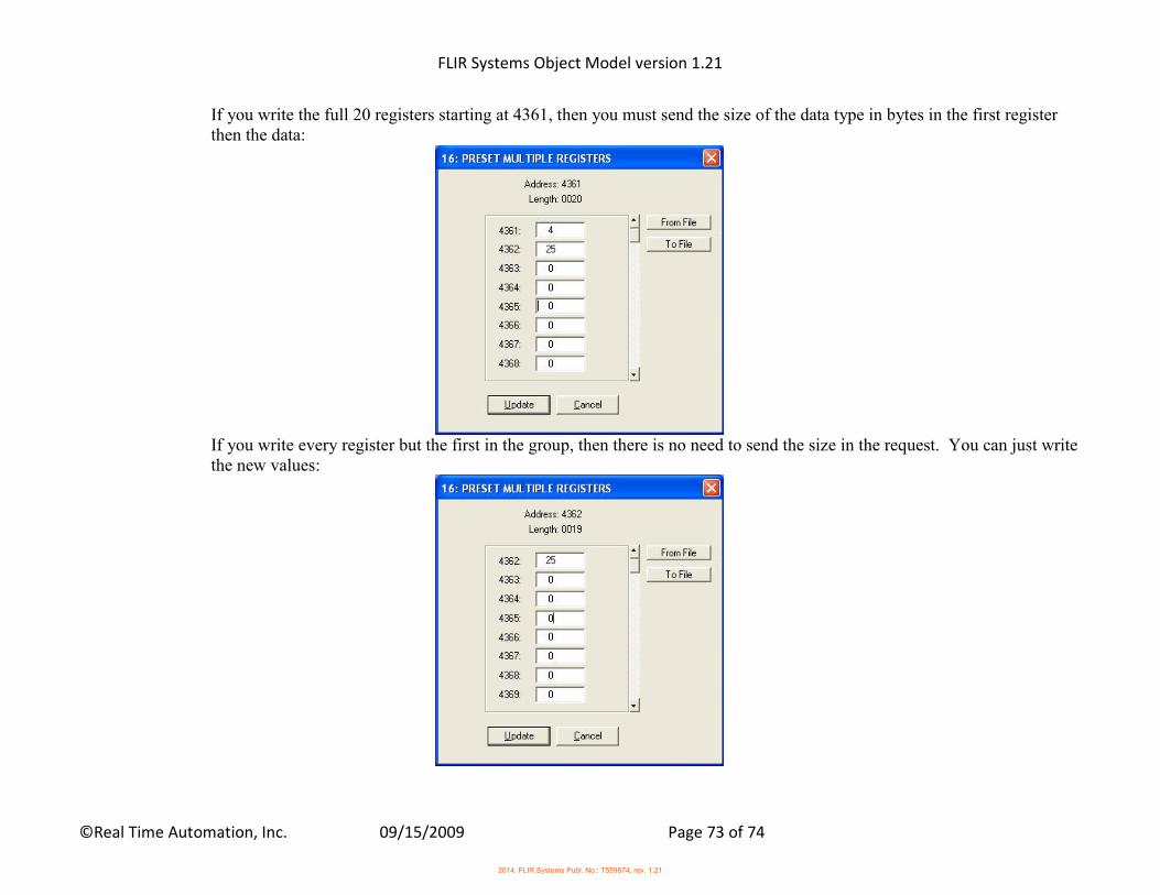
FLIR Systems Object Model version 1.21
©Real Time Automation, Inc. 09/15/2009 Page 73 of 74
If you write the full 20 registers starting at 4361, then you must send the size of the data type in bytes in the first register then the data:
If you write every register but the first in the group, then there is no need to send the size in the request. You can just write the new values:
2014, FLIR Systems Publ. No.: T559874, rev. 1.21
FLIR Systems Object Model version 1.21
©Real Time Automation, Inc. 09/15/2009 Page 74 of 74
Example reading Box 2 Min Temperature: - Modbus Unit ID (Slave ID) = 109 - Starting Register = Holding Register 8101 - Example Min Temperature is 302.25 Kelvin 8101 = 4 8102 = 0x2000 8103 = 0x4397 8104 = 4 8105 = 0x4397 8106 = 0x2000
2014, FLIR Systems Publ. No.: T559874, rev. 1.21