Embed Size (px)
Citation preview

NASA Technical Memorandum 88289
P
Flight Test Techniques for the X=29A Aircraft
John W. Hicks, James M. Cooper, Jr., and Walter J. Sefic
February 1987
(NASA-TH-88289) €LIGHT T E S T 'ICCllNIQUES FOR N87-2 1908 IEE x-29A A I B C R A f l (NASA) 14 p Avail: 131s HC A02/flF 801 CSCL 01c
U n c l a s Hl/OS 0070057
National Aeronautics and Space Ad mini st rat ion
https://ntrs.nasa.gov/search.jsp?R=19870012475 2018-05-14T07:52:40+00:00Z
NASA Technical Memorandum 88289
.
.
Flight Test Techniques for the X-29A Aircraft John W. Hicks, James M. Cooper, Jr., and Walter J. Sefic Ames Research Center, Dryden Flight Research Facility, Edwards, California
1987
National Aeronautics and Space Administration Ames Research Center Dryden Flight Research Facility Edwards. California 93523- 5000
FLIGHT TEST TECHNIQUES FOR THE X-29A AIRCRAFT
John W. Hicks,* James M. Cooper, Jr.,** and Walter J. Se f i c+
NASA Ames Research Center Dryden F l i g h t Research F a c i l i t y
Edwards, Cal i f o r n i a
Abs t rac t
The X-29A advanced techno l ogy demonstrator i s a s ing le -sea t , s ing le -eng ine a i r c r a f t w i t h a forward-swept wing. The a i r c r a f t i nco rpo ra tes many advanced technol ogies be ing considered f o r t h i s c o u n t r y ' s nex t genera t ion o f a i r c r a f t . Th is unusual a i r c r a f t c o n f i g u r a t i o n , which had never been f lown before , requ i red a p rec i se approach t o f l i g h t envelope expansion. Special concerns were s t a t i c wing divergence and a h i g h l y uns tab le a i r - frame. 1-g f l i g h t envelope and t h e maneuver envelope a t h ighe r normal l oad f a c t o r s and angle o f a t tack . Real - t ime a n a l y s i s was requ i red t o c l e a r the envelope i n a safe, e f f i c i e n t manner. cases, t h i s l e d t o development o f a unique r e a l - t i m e a n a l y s i s c a p a b i l i t y . The use o f r e a l - t i m e d i s p l a y s t o p rov ide f o r qu ick a n a l y s i s o f s t a b i l - i t y and c o n t r o l , dynamic and s t a t i c s t ruc tu res , f l i g h t c o n t r o l systems, and o the r systems data g r e a t l y enhanced t h e p r o d u c t i v i t y and sa fe ty of t h e f l i g h t t e s t program.
Th is paper descr ibes t h e r e a l - t ime a n a l y s i s
F1 i g h t envelope expansion i nc luded t h e
I n some
iileihsds afid f : t g k t t ~ ~ t t ~ t k ~ ! . ; . i ~ use.' .'U~!C? t h e envelope expansion o f t h e X-29A a i r c r a f t , i n c l u d i n g new and i n n o v a t i v e techniques t h a t pro- v ided f o r a safe, e f f i c i e n t envelope expansion. The use program w i l l be
ACC
AR
BFF
DR
FCS
FDMS
FM
F SW
9
I TB
LED
MCC
PCM
o f i n t e g r a t e d t e s t blocks i n t h e expansion and i n t h e o v e r a l l f l i g h t t e s t approach discussed.
Nomenclature
au tomat ic camber c o n t r o l
analog reve rs ion
body-freedom f l u t t e r
d i g i t a l reve rs ion
f l i g h t c o n t r o l system
f l i g h t d e f l e c t i o n measurement system
frequency modu la t ion
forward-swept wing
normal l oad f a c t o r
i n t e g r a t e d t e s t b lock
l i g h t - e m i t t i n g d iode
manual camber c o n t r o l
p u l se-code modu la t ion
*Chief Engineer, X-29 Program. A I A A member.
t p r o j e c t Manager , X-29 Program. **Aerospace Engineer.
A I A A member.
This paper is declared a work of the U.S. Government and therefore is in the public domain.
pEst parameter es t ima t ion program
RAV remote ly augmented v e h i c l e
I n t r o d u c t i o n
The unique X-29A forward-swept-wing a i r c r a f t r e q u i r e d a s p e c i a l l y t a i l o r e d f l i g h t t e s t program t o e f f i c i e n t l y , y e t s a f e l y , expand t h e 1-g and maneuver envelopes whi 1 e ga the r ing research da ta t o eva lua te severa l h i g h l y i n t e g r a t e d advanced techno log ies . Conducting a m u l t i d i s c i p l i n a r y t e s t program on a s i n g l e exper imental a i r c r a f t o f r a d i - c a l des ign was very cha l leng ing . The program requ i red t i g h t l y coord ina ted f l i g h t t e s t p lann ing coupled w i t h s p e c i a l l y developed maneuver tech- niques and r e a l - t i m e and p o s t f l i g h t da ta a n a l y s i s c a p a b i l i t i e s . Heavy r e l i a n c e on ground and i n - f l i g h t s i m u l a t i o n and ex tens i ve p r e d i c t i v e pre- f l i g h t a n a l y s i s were a l s o e s s e n t i a l t o program success. Several s p e c i f i c t e c h n i c a l areas, such as c l a s s i c a l f l u t t e r , a e r o s e r v o e l a s t i c i t y , f l i g h t c o n t r o l system (FCS) s t a b i l i t y , s t r u c t u r a l loads, a i r c r a f t systems, p ropu ls ion , performance, and bas i c s t a b i l i t y and c o n t r o l c h a r a c t e r i s t i c s , had LU be C:Fared ofi a sing:e ;:;plane. ?. f l i g h t r a t e o f up t o f o u r f l i g h t s per day ( h i g h f o r an X-type a i r p l a n e ) and two f l i g h t days per week requ i red an emphasis on r e a l - t i m e ana lys is . Spec ia l i zed r e a l - t i m e a n a l y s i s techn iques had t o be developed t o ge t c r i t i c a l answers w h i l e i n f l i g h t t o c l e a r t h e a i r c r a f t t o t h e nex t envelope po in t .
The X-29A p r o j e c t was begun i n 1977 by t h e Defense Advanced Research P ro jec ts Agency (DARPA) and t h e Grumman Aerospace Corporat ion. t h e obvious s a f e t y - o f - f l i g h t advantages o f t h e Edwards A i r Force Base complex, t h e d e c i s i o n was made t o s h i p t h e a i r c r a f t t o Edwards AFB f o r i t s f i r s t f l i g h t and conduct t h e e n t i r e envelope expansion program there . It was shipped th rough t h e Panama Canal, a r r i v i n g a t Edwards AFB i n October 1984. A f l i g h t t e s t team, l oca ted a t t h e NASA Ames Research Center 's Dryden F l i g h t Research F a c i l i t y (Ames-Dryden) and made up o f Ames-Dryden, A i r Force F l i g h t Test Center, and Grumman person- ne l , s u c c e s s f u l l y completed t h e f i r s t f l i g h t on December 14, 1984. Pmes-Dryden was t h e respon- s i b l e t e s t o rgan iza t i on , w i t h s a f e t y - o f - f l i g h t and opera t i ona l r e s p o n s i b i l i t y . (Fu r the r d e t a i l s of programmatic i ssues can be found i n Ref. 1.) f l i g h t envelope expansion was completed by t h e end o f 1986. o f t h e 1-g f l i g h t envelope i n Mach number and a l t i t u d e and t h e angle o f a t t a c k and normal l o a d f a c t o r maneuvering envelope t o t h e l i m i t s d e t e r - mined by t h e FCS and s t r u c t u r a l ground t e s t s .
Wi th t h e r e s t r i c t i o n o f a s i n g l e a i rp lane , severa l t e c h n i c a l d i s c i p l i n e t e s t requirements and envelope c learance tasks had t o be i n t e g r a t e d i n t o t h e f l i g h t program. s t r u c t u r a l loads, s t r u c t u r a l dynamics, a i r c r a f t systems, and propu ls ion . More research -o r ien ted
A _
Because o f
The
The pr ime o b j e c t i v e was t h e expansion
These inc luded c o n t r o l s ,

I n v e s t i g a t i o n s o f a i r c r a f t performance, l o c a l aerodynamics. handl iny q u a l i t i e s , and s t a b i l i t y and c o n t r o l d e r i v a t i v e e x t r a c t i o n were a l s o inc luded. S t r u c t u r a l loads had t o c l e a r bo th t h e bas i c a i r f rame loads envelope i n t h e au tomat ic camber c o n t r o l (ACC) winy c o n f i g u r a t i o n mode and t h e s t a t i c winy diveryence i n manual camber con- t r o l (MCC) mode.
A i r c r a f t Descr i pt+
.The X-2YA advanced techno loyy demonstrator ( F i y . 1 ) i s a s ing le -sed t a i r c r a f t desiyned t o eva lua te t h e s y n e r y i s t i c e f f e c t s o f severa l i n t e - g r a t e d techno loy ies t o advance t h e s t a t e o f t h e a r t o f t h i s count ry 's nex t genera t ion o f f i y h t e r a i r c r a f t . I t s most no tab le f e a t u r e i s t h e f o r - ward-swept winy (FSW) hav ing a 33.73O quar te r - chord winy sweep. The pr imary wingbox i s covered w i t h a e r o e l a s t i c a l l y t a i l o r e d y r a p h i t e epoxy covers a t tached t o convent ional aluminum and t i t a - nium spars. The load-bear iny wing covers g i v e a 1 i yh twe iyh t , . ye t strong, s t r u c t u r e t h a t c o n t r o l s winy d e f l e c t i o n and the tendency o f t h e FSW toward winy divergence. The winy has a 5 -percent - th ick s u p e r c r i t i c a l a i r f o i l , a f i x e d l ead ing edge, and f u l l - s p a n , dual-hinyed t r a i l i n g f laperons , which y i e l d h igh l i f t dur iny t a k e o f f and l a n d i n g and p rov ide t h e so le source o f l a t e r a l contro.1 f o r t h e a i r c r d t t . The f l a p i s a l so used t o vary t h e wing camber e i t h e r au tomat i ca l l y w i t h t h e cont inuous ACC mode o r manually by t h e p i l o t us ing t h e d i s c r e t e MCC mode. Flaperon d e f l e c t i o n ranye i s f rom 10' t r a i l i n y edge up t o 25" t r a i l i n g edge down. The winy aerodynamics are coupled w i t h a f u l l - a u t h o r i t y , h igh - ra te canard l o c a t e d fo rward o f t h e winys a t t he lead iny edye o f t h e eny ine i n l e t s . The t r a v e l o f t h e canards i s 30' l ead ing edge up t o 60° leading edge down a t a maximum r a t e o f 100 dey/sec. Aft-mounted fuse laye s t r a k e f l a p s w i t h a *30° t r a v e l work i n con junc t i on w i t h t h e canards and symmet r ica l l y d e f l e c t e d f l ape rons t o p r o v i d e a unique th ree-sur face a i r c r a f t p i t c h c o n t r o l . A s ing le -p iece rudder p rov ides yaw c o n t r o l . The a i r c r a f t forward o f t h e engine i n l e t s cons is t s o f a standard F-5A nose sec t i on , c o c k p i t , and nose gear.
The nomina l l y 35-percent negat ive s t a t i c marg in o f the a i r c r a f t i s s t a b i l i z e d by a h i g h l y auymented t r i p l e x d i g i t a l - a n a l o g f l y -by -w i r e c o n t r o l system. The FCS has t h r e e modes: normal (p r imdry ) mode, d i g i t a l r e v e r s i o n (DR) mode, and analog reve rs ion (AR) mode.
P ropu ls ion i s provided by a s i n g l e General E l e c t r i c F404-6E-400 a f t e r b u r n i n g engine, ra ted a t 16,000 I b t h r u s t a t sea l e v e l . The engine i s mounted i n a fuselaye w i t h two side-mounted, f i x e d - geometry i n l e t s t h a t were desiyned f o r t ranson ic performance. A i r c r a f t t a k e o f f gross weight i s 17,800 l b w i t h a 4000-lb f u e l capac i t y i n t h e fuse laye and s t r a k e tanks.
Instrument a t ion The f l i y h t t e s t i ns t rumen ta t i on system
( F i y . 2 ) was t a i l o r e d f o r envelope expansion and some f l i g h t research measurements. Because o f a i r f rame i n t e r n a l volume c o n s t r a i n t s , a 1 0 - b i t remote u n i t pu 1 se-code modul a t i on (PCM) system was used f o r da ta aqu is i t i on . The ou tpu ts o f t h e f i v e PCM u n i t s and t h e A R I N C 429 (Aeronaut ica l Radio,
I nco rpo ra ted ) da ta bus a re combined i n an i n s t r u - men ta t i on component known as an i n t e r l e a v e r and a r e ou tpu t as a s e r i a l PCM stream. I n a d d i t i o n , a constant-bandwidth frequency modu la t ion (FM) system i s i n s t a l l e d t o acqu i re high-response a c c e l e r a t i o n and v i b r a t i o n data. t h e FM m u t i p l e x e r i s rou ted t o a prernoaulat ion m i x e r where i t i s combined w i t h t h e p i l o t ' s voice. A i r - t o -g round te lemet ry i s t h e o n l y source o f a i r - c r a f t da ta s ince t h e r e i s no onboard reco rd iny system. Ins t rumen ta t i on p r o v i s i o n s i nc lude measurements f o r s t r u c t u r a l loads and dynamics, f l i g h t c o n t r o l s , s t a b i l i t y and c o n t r o l , a i r c r a f t subsystems, p ropu ls ion , and performance. The F404-6E-400 eny ine con ta ins an F-18-s ty le f l i y h t t e s t t h r u s t i n s t r u m e n t a t i o n system, bu t on l y t h e GE bas i c eny ine i n s t r u m e n t a t i o n p o r t i o n was p u t i n t o ope ra t i on f o r t h e envelope expansion phase. More d i scuss ion o f engine i ns t rumen ta t i on can be found i n Ref. 2.
E x t e r n a l l y , 12 i n f r a r e d l i g h t - e m i t t i n g diodes (LEDs) were mounted across the t o p o f t he r i g h t w ing as p a r t o f t h e f l i g h t d e f l e c t i o n measurement system (FDMS). The LEDs t r a n s m i t t e d l i g h t t o a dua l r e c e i v e r mounted i n t h e r i g h t s ide o f t h e fuse lage above t h e w ingroot . The l e f t wing, canard, s t rake , and s t r a k e f l a p upper surfaces were ins t rumented w i t h 179 f lush-mounted s t a t i c p ressure taps t o measure aerodynamic p ressure d i s t r i b u t i o n . F i n a l l y , each wing pontoon, con- t a i n i n g t h e mid- and outboard f l a p e r o n h y d r a u l i c ac tua to r , was f i t t e d w i t h a spec ia l aft-mounted f l a p e r o n eccent r i c - ro ta ry -mass s t r u c t u r a l e x c i t a - t i o n system t o i n v e s t i y a t e t h e supersonic f l a p - t a b single-degree-of- f reedom f l u t t e r p o t e n t i a l . The FDMS and s t r u c t u r a l e x c i t a t i o n system a re tempor- a r y e x t e r n a l dev ices used s p e c i f i c a l l y t o a s s i s t i n t h e s t r u c t u r a l c learance o f t h e f l i g h t envelope.
The ou tpu t o f
c
b
Real-Time Processiny and D isp lay
The NASA Ames-Dryden Western Aeronaut ica l Test Range prov ided t h e r e a l - t i m e m o n i t o r i n g and analy- s i s c a p a b i l i t y f o r t h e envelope expansion work. Since a l l data f rom t h e X-29A a i r c r a f t were a v a i l - a b l e on l y over a t e l e m e t r y downlink d u r i n g f l i g h t , a l l da ta had t o be recorded, and i n some cases analyzed, i n r e a l t i m e on t h e ground. The telem- e t r y downlink and da ta p rocess ing setup i s out- l i n e d i n F ig . 3. The range prov ides te lemet ry a c q u i s i t i o n and processing, r e a l - t i m e da ta analy- s i s and d i sp lay , vo i ce communication l i n k s , radar t r a c k i n g f o r space p o s i t i o n i n g , and v ideo d i sp lays o f t h e a i r c r a f t i n f l i g h t . Th is i n f o r m a t i o n was made a v a i l a b l e t o two m iss ion c o n t r o l rooms, t h e "b lue room" and t h e s p e c t r a l ana lys i s f a c i l i t y , which worked i n p a r a l l e l t o d i r e c t t h e f l i g h t s . The b l u e room c o n s i s t s o f 12 s t r i p cha r t s , numer- ous CRT d i sp lays , and a te rm ina l console hookup t o a computer p r o v i d i n y r e a l - t i m e da ta proces- s iny . Gould SEL 32/55 and 32/77 minicomputers a r e used t o process te lemet ry i n fo rma t ion , t o c a l i b r a t e it, t o conver t i t t o eng ineer ing u n i t s , and t o d i s p l a y i t t o t h e c o n t r o l room. Th is con- t r o l room con ta ins the t e s t conductor, ranye com- mun ica t ions personnel , p r o j e c t management, and d i s c i p l systems c o n t r o l
The s i x s t r
2
ne engineers from c o n t r o l s , p ropu ls ion , 1 oads , and aerodynamic s t ab i 1 i t y and
spec t ra l ana lys i s f a c i l i t y cons i s t s o f p cha r t s , CRT d i sp lays , a communications
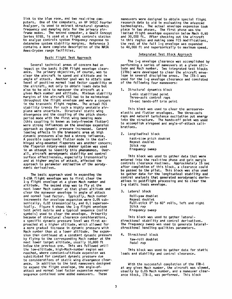
l i n k t o t h e b l u e room, and two rea l - t ime com- pu te rs . Analyzer, i s used t o e x t r a c t s t r u c t u r a l dynamics f requency and damping data f o r t h e pr imary a i r - frame modes. Se r ies 9780, i s used a t a f l i g h t c o n t r o l s s t a t i o n t o analyze c o n t r o l s system frequency response t o de termine system s t a b i l i t y margins. Reference 3 con ta ins a more complete d e s c r i p t i o n o f t h e NASA Ames-Dryden range f a c i l i t i e s .
One of t h e computers, an HP 5451C Four ie r
The second computer, a Gould Concept
Basic F1 i g h t Test Approach
Several t echn ica l areas o f concern had an impact on t h e bas i c X-29A f l i g h t envelope c l e a r - ance. The p r imary o b j e c t i v e , o f course, was t o c l e a r t h e a i r c r a f t i n speed and a l t i t u d e and i n ang le o f a t tack . Another goal was t o a t t a i n some l e v e l o f p o s i t i v e normal l oad f a c t o r c a p a b i l i t y on t h e a i r c r a f t , n o t o n l y t o o b t a i n loads da ta b u t a l s o t o be a b l e t o maneuver the a i r c r a f t a t a g i ven Mach number and a l t i t u d e . Minimum s t a b i l i t y margins o f t h e a i r c r a f t FCS had t o be maintained th roughout t h e f l i g h t envelope and were a concern i n t h e t r a n s o n i c f l i g h t regime. The ac tua l FCS s t a b i l i t y t rends f o r such a h i g h l y uns tab le a i r - p lane were uncer ta in . S t r u c t u r a l s t a t i c wing d ivergence and t h e coup l i ng o f t h e p i t c h sho r t - p e r i o d mode w i t h t h e f i r s t wing bending mode ( t h i s coup1 i n g i s known as body-freedom f l u t t e r ) were s t rong i n f l u e n c e s on t h e envelope expansion approach as dynamic p ressure increased. Canard l o a d i n g e f f e c t s i n t h e t ranson ic area a t h igh dynamic pressures a l s o had a s t rona in f luence. A p o s s i b l e supersonic f l u t t e r mode i n t h e dua l - h inged wing-mounted f laperons was another concern; t h e f l a p e r o n rotary-mass shaker system was used i n an a t tempt t o i d e n t i f y t h i s phenomenon. a l l , a i r c r a f t aerodynamic s t a b i l i t y and c o n t r o l su r face e f fec t i veness , e s p e c i a l l y t r a n s o n i c a l l y and a t h ighe r angles o f a t tack , a f f e c t e d the approach t o parameter es t ima t ion o f t h e aerody- namic d e r i v a t i v e s .
The b a s i c approach used i n expanding t h e X-29A f l i g h t envelope was t o f i r s t c l e a r the 1-g f l i g h t envelope a t a g iven Mach number and a l t i t u d e . The second s tep was t o f l y a t t h e nex t lower Mach number a t t h a t g iven a l t i t u d e and c l e a r t h e maneuver envelope i n angle o f a t t a c k and normal l oad f a c t o r . T y p i c a l l y , Mach number increments f o r envelope expansion were 0.05 sub- s o n i c a l l y , 0.02 t r a n s o n i c a l l y , and 0.1 superson- i c a l l y . F i g u r e 4 shows t h e 1-g f l i g h t envelope t e s t p o i n t m a t r i x and a t y p i c a l sequence ( s o l i d symbols) used t o c l e a r the envelope. P r i m a r i l y because of s t r u c t u r a l c learance cons idera t ions , a s p e c i f i c dynamic pressure l e v e l was f i r s t ap- proached a t a h ighe r a l t i t u d e , which al lowed f o r a more gradual inc rease i n dynamic p ressure w i t h Mach number than a t a lower a l t i t u d e . The expan- s i o n then cont inued a t a cons tan t dynamic pressure by f l y i n g t o t h e corresponding Mach number a t t he nex t lower t a r g e t a l t i t u d e , u s u a l l y 10,000 f t below t h e prev ious one. Th is was fo l l owed u n t i l t h e low-a1 t i t u d e , high-Mach-number reg ion was reached, where constant-a1 t i t u d e expansion was s u b s t i t u t e d f o r cons tan t dynamic pressure due t o cons ide ra t i ons o f s t a t i c wing divergence c l e a r - ance. I n a d d i t i o n t o t h e t e s t maneuvers designed t o expand t h e f l i g h t envelope, t h e angle-of- a t t a c k and normal l oad f a c t o r expansion maneuver sequence conta ined some added maneuvers.
Over-
These
maneuvers were designed t o o b t a i n spec ia l f l i g h t research da ta t o a i d i n eva lua t i ng t h e advanced techno log ies . The ac tua l envelope expansion took p lace i n two phases. l i m i t e d f l i g h t envelope expansion below Mach 0.60 and 30,000 ft. i n t h i s reg ion and making some FCS mod i f i ca t i ons , t h e r e s t o f t h e f u l l 1-g envelope was expanded t o 40,000 f t and superson ica l l y t o maximum speed.
The f i r s t phase was t h e
A f t e r checking ou t t h e a i r c r a f t
I n teg ra ted Test B1 ock Approach
The 1-g envelope clearance was accompl i shed by per fo rming a s e r i e s o f maneuvers a t a g iven a l t i - t ude and Mach number. Two i n t e g r a t e d t e s t b locks ( ITBs) were developed t o c l e a r t h e a i r c r a f t enve- l ope i n several d i s c i p l i n e areas. The ITB-1 was used f o r t h e 1-g envelope c learance and cons is ted o f t h e f o l l o w i n g f o u r maneuvers:
1. S t r u c t u r a l dynamics b lock 1-min s t a b i l i z e d p o i n t Three-axi s c o n t r o l raps 15-sec hands-of f t r i m p o i n t
Th is b lock was used t o c l e a r t h e aeroservo- e l a s t i c and f l u t t e r envelopes. raps and n a t u r a l t u rbu lence e x c i t a t i o n pu t energy i n t o t h e s t ruc tu re . The hands-off p o i n t was used t o accomplish a i rspeed and ang le-o f -a t tack c a l i - b ra t i ons .
The th ree -ax i s
2. Long i tud ina l b lock FaSt-SIOW pitch doub le t Repeat doub le t S t i c k rap Frequency sweep
Th is b lock was used t o ga ther da ta t h a t were en tered i n t o t h e rea l - t ime phase and ga in margin c o n t r o l s c learance rou t ines . a f t e r comple t ion o f t h i s block, a c learance cou ld be passed t o t h e p i l o t . Th i s b lock was a l s o used t o ga ther da ta f o r t h e l o n g i t u d i n a l s t a b i l i t y and c o n t r o l a n a l y s i s t h a t generated aerodynamic d e r i v - a t i v e s i n p o s t f l i g h t processing and t o c l e a r t h e
Approximately 15 sec
1-g s t a t i c . loads envelope.
3. La te ra l b lock R o l l -yaw doub le t Repeat doub le t F u l l - s t i c k 0' t o 60' r o l S t i c k rap Frequency sweep
Th is b lock was used t o ga d i r e c t i o n a l s t a b i l i t v and con
s, l e f t and r i g h t
he r l a t e r a l - r o l d e r i v a t i v e s .
The frequency sweep was used t o generate l a t e r a l - d i r e c t i o n a l hand l i ng q u a l i t i e s parameters.
4. D i r e c t i o n a l b lock Yaw-rol l doub le t Pedal rap
Th is b lock was used t o ga ther da ta f o r s t a t i c loads and s t a b i l i t y and c o n t r o l clearance.
With t h e successful comple t ion o f t h e ITB-1 a t any g iven Mach number, t h e a i r c r a f t was slowed, u s u a l l y by 0.05 Mach number, and a maneuver c l e a r - ance block, ITB-2, was performed. Th is b lock
3

expanded t h e ang le-o f -a t tack , normal l oad f a c t o r , and maneuver c a p a b i l i t i e s o f t h e v e h i c l e by i n c l u d i n g t h e f o l l o w i n g maneuvers:
1. Steady-heading s ides l i p s 3" s i d e s l i p Fu l l -peda l o r l i m i t s i d e s l i p
These were used t o gather s t a t i c loads and l a t e r a l - d i r e c t i o n a l s t a b i l i t y and c o n t r o l data.
2. R o l l -yaw doub le ts a t half-maximum s i d e s l i p
3. F u l l - s t i c k 0" t o 60" r o l l s , l e f t and r i g h t
These r o l l s were used t o ga ther loads, con- These were t r o l s , and hand1 i n g qual i t i e s data.
b u i l d u p maneuvers t o t h e 360" r o l l .
4. F u l l - s t i c k 360" r o l l , l e f t and r i g h t
These r o l l s were used t o gather loads, c o n t r o l s , and hand l ing q u a l i t i e s data.
5. R o l l - p i t c h s tep i npu ts
c o n t r o l and a i r c r a f t responses were used f o r sim- u l a t i o n c o r r e l a t i o n work.
6. Cons tan t -a l t i t ude windup t u r n
These 0.5-in step i n p u t s and t h e r e s u l t a n t
Data from these maneuvers were used i n the loads, c o n t r o l s , and wing pressure d i s c i p l i n e s f o r 1 oad clearance. These maneuvers were accomplished t o t h e c lea red loads envelope t o e s t a b l i s h da ta t h a t would a l l o w fu r the r load clearance.
7. Constan t - th rus t windup t u r n s
formance d i s c i p l i n e t o d e r i v e drag po la rs .
8. Pushover-pul lups
Th is w i ngs-1 eve1 sequence consi s ted o f 1-g s t a b i l i z e d f l i g h t , a pushover t o 0 g fo l lowed by a p u l l u p t o 2 g, and a r e t u r n t o 1-g s t a b i l i z e d f l i g h t . d rag p o l a r shapes and t o f i l l i n t h e 0- t o 1-g loads range.
Data from these tu rns were used i n t h e per -
These maneuvers were used t o develop
The ITB-1 and ITB-2 maneuvers c lea red the ACC f l i g h t c o n t r o l mode. The MCC f l i g h t c o n t r o l mode was then evaluated by a f u l l ITB-1 fo l l owed by pushover-pul lups and windup tu rns . were used p r i m a r i l y i n wing divergence ana lys i s t o e s t a b l i s h t h e s t a t i c wing divergence dynamic p ressure p red ic t i ons .
By us ing t h e i n teg ra ted t e s t b lock approach, t h e X-29A a i r c r a f t was taken through t h e f l i g h t envelope w h i l e s imultaneously c l e a r i n g areas o f concern i n va r ious d i s c i p l i n e s .
lopes, t h e emphasis sh i f t ed t o ga the r ing research data. Numerous maneuver b locks were se t up f o r t h e d i f f e r e n t d i s c i p l i n e s . For example, t h e loads research group es tab l i shed t h e f o l l o w i n g s e t o f maneuvers t o b u i l d up t h e i r X-29A data base:
These da ta
Having c lea red the 1-g and maneuvering enve-
1. Symmetric p u l l u p 2. Symmetric pushover 3. L e f t and r i g h t t u r n reve rsa l 4. L e f t and r i g h t rudder k i c k 5. L e f t and r i g h t rudder reve rsa l
S t r u c t u r a l Dynamics Techniques
The pr imary r e a l - t ime a n a l y s i s techn ique used t o t r a c k t h e s t r u c t u r a l frequency and damping o f f i v e main modes was t h e random-data auto-power- spectrum ana lys is . The f i v e modes inc luded t h e f i r s t symmetric and an t isymmet r ic wing bending modes, t h e f i r s t fuse lage v e r t i c a l and l a t e r a l bending modes, and t h e f i r s t v e r t i c a l f i n bending mode. Mon i to r i ng t h e symmetric f i r s t wing bending modal frequency i n r e a l t i m e was e s p e c i a l l y impor- t a n t i n t r a c k i n g t h e onset o f t h e body-freedom f l u t t e r (BFF) phenomenon. c o u p l i n g occurs a t about 2 Hz, onset was p red ic ted t o beg in as e a r l y as 5 Hz. The BFF phenomenon a c t s as a p recursor t o t h e s t a t i c wing d ivergence problem. A t a g iven Mach number and a l t i t u d e con- d i t i o n , da ta from an approx imate ly 60-sec i n t e r v a l were requ i red f o r ana lys is . The requ i red maneuver cons is ted o f a s t a b i l i z e d p o i n t w i t h random a i r t u rbu lence and th ree -ax i s s t i c k rap i npu ts . The e c c e n t r i c rotary-mass f laperon e x c i t a t i o n system was a l s o used a t t imes as an i n p u t f o r t h e e n t i r e a i r f rame. The pr imary f u n c t i o n o f t h e f l a p e r o n e x c i t a t i o n system, however, was t o p rov ide wing e x c i t a t i o n t o t r a c k t h e supersonic f l a p - t a b single-degree-of- f reedom f l u t t e r .
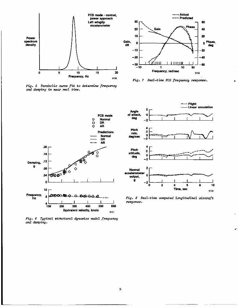
A f a s t F o u r i e r ana lys i s was performed on t h e da ta w i t h a minicomputer us ing a frame s i z e o f 1024 da ta samples a t 100 samples/sec. On t h e ground, an analog bandpass f i l t e r was used t o i s o l a t e each s t r u c t u r a l mode. I n a s i m i l a r manner, p o s t f l i g h t ana lys i s o f t h e same maneuver p o i n t s was performed on the canard random data us ing a frame s i z e o f 2048 samples a t 200 samples/ sec. The inve rse Four ie r t rans fo rm was computed t o o b t a i n t h e a u t o c o r r e l a t i o n f u n c t i o n f rom which a da ta c u t o f f t i m e cou ld be se lec ted and smoothing performed t o o b t a i n a smoothed auto-power-spectrum d i s p l a y (F ig . 5). Each mode i n t h e auto-power- spectrum d i s p l a y was f i t w i t h a least-squared- e r r o r p a r a b o l i c curve whose modal frequency was t h e maximum ampl i tude o f t h e curve, and t h e damping was ex t rac ted us ing t h e ha1 f-power tech- nique. More s p e c i f i c i n f o r m a t i o n on t h e method can be found i n Ref. 4. The ac tua l frequency and damping o f t h e f i v e main modes were compared i n r e a l t ime w i t h precomputed p r e d i c t i o n s (F ig . 6). Damping o r modal frequency t h a t were s i g n i f i - c a n t l y lower than p r e d i c t i o n s caused a h a l t i n t h e envelope expansion u n t i l t h e problem was understood.
Whi le ac tua l mode
S t a b i l i t y and Cont ro l
A i r c r a f t aerodynamic c h a r a c t e r i s t i c s were analyzed by e x t r a c t i n g the nondimensional ized aerodynamics d e r i v a t i v e s , us ing an i n t e r a c t i v e parameter es t ima t ion program known as pEst. Special t h ree -ax i s s t i c k doub le t maneuvers were used as da ta i n p u t t o t h e computer program. To inc rease t h e i n f o r m a t i o n conten t o f t h e data, these maneuvers cons is ted o f p a i r s o f f a s t and slow doub le ts i n each ax i s , which were repeated
4

f o r t h e l o n g i t u d i n a l and l a t e r a l cases. The h i g h l y augmented three-surface i n t e g r a t e d p i t c h c o n t r o l made the e x t r a c t i o n of t h e t h r e e separate c o n t r o l su r face d e r i v a t i v e s imposs ib le du r ing the envelope expansion phase of t h e program. reason, o n l y an e f f e c t i v e p i t c h c o n t r o l power d e r i v a t i v e cou ld be ex t rac ted , rep resen t ing t h e combined p i t c h c o n t r o l of a l l t h r e e surfaces. The Cram'er-Rao bound was app l i ed t o determine the u n c e r t a i n t y l e v e l s i n t h e i n d i v i d u a l d e r i v a t i v e s , and t h e da ta s c a t t e r was used t o determine the v a l i d i t y o f t h e d e r i v a t i v e s .
For t h i s
The h igh l o n g i t u d i n a l s t a t i c i n s t a b i l i t y o f t h e X-29A a i r c r a f t requ i res a r t i f i c i a l s t a b i l i z a - t i o n by t h e high-response FCS. As a r e s u l t , t h e a i r c r a f t response i s dominated by t h e FCS r a t h e r than by aerodynamics. e r a t i o n s and t h e dominance o f t h e FCS necessi- t a t e d t h e development o f a rea l - t ime ana lys i s techn ique t o mon i to r t he l o n g i t u d i n a l -ax i s con t ro l system s t a b i l i t y . A f as t Four ie r t rans fo rm tech- n ique was used t o measure open-loop frequency response and the corresponding phase margin a t t h e ga in crossover frequency and ga in margins a t t h e h i g h and low phase crossover f requencies. Real- t ime c a l c u l a t i o n s were compared w i t h pre- f l i g h t computed p r e d i c t i o n s as the envelope expanded from p o i n t t o p o i n t i n Mach number and a l t i t u d e . The s t a b i l i t y c r i t e r i o n used t o h a l t envelope expansion t o t h e nex t Mach number p o i n t was a minimum ga in margin o f 3 dB o r a phase marg in o f 22.5', o r both, based on MILSPEC-F-9490D (Ref. 5). S i g n i f i c a n t adverse t rends toward those min imum d i w siuwtd u i halted the e f i v c : ~ p ~ ~npan- s i o n process u n t i l t h e s i t u a t i o n was understood and a remedy was developed. b i l i t y was o f g rea t value t o t h e program. p o s t f l i g h t ana lys i s , o n l y one expansion p o i n t cou ld have been f lown per f l i g h t and on ly one f l i g h t every two t o t h r e e days. The rea l - t ime imp lementa t ion o f t h e s t a b i l i t y margin ana lys i s and r e a l - t i m e c learance o f t h e FCS performance a l lowed t h e c learance o f two o r t h r e e Mach number and a l t i t u d e p o i n t s per f l i g h t a t up t o fou r f l i g h t s per day. Th is g r e a t l y acce le ra ted t h e envelope expansion phase.
The r e a l - t ime open-loop frequency response a n a l y s i s requ i red about 52 sec o f f l i g h t data recorded a t 40 samples/sec, o r a t o t a l o f 2048 t ime h i s t o r y da ta po in ts . The maneuver b lock cons is ted o f a s t i c k rap, a doub le t , and a frequency sweep i n t h e p i t c h ax is . Typical r e s u l t s of t h e r e a l - t i m e p l o t ou tpu t a re dep ic ted i n Fig. 7. Fu r the r d e t a i l s o f t he technique development can be found i n Ref. 6. I n a d d i t i o n t o de termin ing t h e FCS phase and ga in margins, a r e a l - t i m e t ime h i s t o r y ove r lay o f t h e ac tua l a i r - c r a f t f l i g h t response and p red ic ted response was made from t h e same data. The p red ic ted response was generated i n r e a l t ime by e n t e r i n g t h e con t ro l d e f l e c t i o n s measured i n f l i g h t and the i n i t i a l f l i g h t c o n d i t i o n s i n t o t h e mathematical models and c a l c u l a t i n g t h e p red ic ted response. A t y p i c a l example i s shown i n Fig. 8. Add i t i ona l d e t a i l s o f t h i s method are conta ined i n Ref. 7. Th i s r e a l - t i m e comparison was an a d d i t i o n a l check on t h e FCS s t a b i l i t y a n a l y s i s i n t h a t it detec ted any a i r - c r a f t s t a b i l i t y degradat ion when c l e a r i n g the a i r - c r a f t t o t h e nex t t e s t po in t . An o v e r a l l degra- d a t i o n i n a i r c r a f t s t a b i l i t y r e l a t i v e t o p red ic -
Sa fe ty -o f - f l i g h t consid-
Th is r e a l - t i m e capa- Using
t i o n s f o r any s i g n i f i c a n t a i r c r a f t response was cause t o Slow or ha1 t envelope expansion.
In-F1 i g h t D e f l e c t i o n Measurement
The FDMS was u t i l i z e d f o r wing s t a t i c s t r u c - t u r a l d ivergence clearance; data were compared w i t h a e r o e l a s t i c wing d e f l e c t i o n p r e d i c t i o n s . da ta were a l so used i n ana lys i s programs designed t o d e r i v e t h e es t imated wing s t a t i c d ivergence dynamic pressure. The e n t i r e system was loca ted on t h e r igh t -hand s i d e of t h e a i r c r a f t , w i t h t h e 12 LEDs on t h e upper r i g h t wing su r face (F ig . 9). These LEDs were focused on two d iode a r r a y r e c e i v e r s t h a t were mounted i n t h e r i gh t -hand s i d e of t h e fuselage behind a 5- by 7 - i n g lass window, j u s t above t h e wingroot. focused on the inboard se t o f LEDs and t h e o t h e r on t h e outboard se t . Typ ica l r e s u l t s , ob ta ined p r i m a r i l y i n p o s t f l i g h t da ta reduc t ion , can be seen i n Fig. 10. Real- t ime computat ion and d i s - p l a y o f t h e da ta were poss ib le bu t no t deemed necessary f o r envelope clearance. W i ngbox t w i s t da ta ob ta ined from d e f l e c t i o n measurements a r e p l o t t e d as a f u n c t i o n o f wing semispan. Chordwise and spanwise r e l a t i v e displacement o f t h e LED t a r - ge ts y i e l d e d very r e l i a b l e measurements o f wing t w i s t i n g and bending, respec t i ve l y .
The
One d iode a r ray
S t r u c t u r a l Loads
The s t r u c t u r a l loads c learance o f t h e X-29A a i r c r a f t was accomplished f o r bo th ACC and MCC wing modes p r i m a r i l y by p o s t f l i g h t ana lys i s . 5 t r t c t t r ; ? 1 c;d 1 ; m i + nn..nl n n n c ..I_Cn A n , , n l n n n A
80 percent and 100 percent o f l i m i t , based on the 80-percent des ign l oad ground p roo f t e s t . l i m i t s were monitored i n r e a l t ime on a c o l o r CRT p r e s e n t a t i o n f o r t h e l e f t canard, l e f t l a t e r a l fuselage, l e f t wing, and v e r t i c a l t a i l loads. A t y p i c a l rea l - t ime p resen ta t i on i s shown i n Fig. 11. Exceeding any o f these s t r u c t u r a l loads envelopes would have caused t h e p i l o t t o break o f f a maneuver, h a l t i n g any f u r t h e r envelope expansion t o t h e nex t h ighe r Mach number. Some r e s u l t s were used t o modify any f u r t h e r maneuvering t h a t migh t cause a i r f rame loads t o exceed t h e i r l i m i t s . Th i s u s u a l l y r e s u l t e d i n a r e a l - t i m e c a l l t o decrease o r l i m i t t h e normal l oad f a c t o r t a r g e t c o n d i t i o n o f a g iven maneuver. For each a i r f r a m e component, t o rque loads were compared w i t h bending loads com- puted from i n - f l i g h t s t r a i n gage measurements.
nons t ruc tu ra l l oad l i m i t observed d u r i n g r e a l t ime. The mon i to r i ng o f t h i s l i l n i t was necessi- t a t e d by t h e s ingle-system h y d r a u l i c a c t u a t o r c a p a b i l i t y . The l i m i t was se t a t 80 percent o f t h e ac tua to r l i m i t de f i ned i n terms o f an equiva- l e n t l oad measured a t t h e ac tua to r . The common l o a d f a c t o r expansion maneuvers, such as t h e cons tan t - th rus t pushover-pul lup maneuver from 1-9 s t a b i l i z e d f l i g h t and t h e c o n s t a n t - a l t i t u d e windup t u r n , were used t o o b t a i n loads data.
S t a t i c wing divergence c learance was accom- p l i s h e d by use of b o t h s t r a i n gage and FDMS data. Separate p o s t f l i g h t a n a l y s i s o f t h e da ta w i t h t h e Southwell technique8 gave an es t imate o f t h e d ivergence speed, which was compared w i t h p red ic - t i o n s . The canard s t r a i n gage da ta were analyzed i n a s i m i l a r way t o determine canard divergence
8 1 1 1 1 1 .. c I l . C . "yc' ..-I c ..'.L."r-" f e r
These
The canard ac tua to r l oad l i m i t was t h e o n l y
5

speed and were compared w i t h p r e d i c t i o n s . MCC wing mode al lowed f o r t e m p o r a r i l y f i x e d wing geometry d u r i n g a c o n s t a n t - a l t i t u d e windup t u r n , f rom which t h e loads da ta were generated. Th is mode a l lowed t h e p i l o t t o manual ly s e t d i s c r e t e 5' increments o f f laperon f rom 5' t r a i l i n g edge up t o 25' ( f u l l ) t r a i l i n g edge down.
The
Remotely Augmented Veh ic le
To a s s i s t i n t h e c o l l e c t i o n o f da ta o f h i g h e r q u a l i t y and l a r g e r quant i t y , t h e remotely aug- mented v e h i c l e (RAV) system (F ig. 12) was i n c o r - pora ted i n t o t h e X-29A a i r c r a f t . The p i 1 o t -ass i s t v e r s i o n o f t h e RAV system was t e s t e d i n t h i s phase. A i r c r a f t s ta te v a r i a b l e s c a l c u l a t e d f rom t h e telemetered data a re i n p u t t o t h e computers, which generate guidance and c o n t r o l in fo rmat ion .
t h e f i r s t mode, a ground-based computer d r i v e s a s e t o f a i r b o r n e guidance needles (F ig . 12(b) ) th rough a r a d i o up l ink . The ground-based computer c a l c u l a t e s t h e f l i g h t p a t h r e q u i r e d t o accomplish t h e maneuver and then computes e r r o r s i g n a l s from t h e d e s i r e d and actual va lues i n t h e form o f p i t c h , r o l l , and t h r o t t l e p o s i t i o n . These e r r o r s a r e te lemetered t o the v e h i c l e and d isp layed as commands t o t h e p i l o t us ing t h e ins t rument l a n d i n g system needles and the speed bug as i n d i c a t o r s . Th is guidance a s s i s t s t h e p i l o t n o t o n l y i n f l y i n g maneuvers more p r e c i s e l y bu t a l s o i n t h e t r a n - s i t i o n t o new t e s t po ints .
The RAV system has two o p e r a t i n g modes. I n
The maneuvers c u r r e n t l y env is ioned f o r t h i s mode i n c l u d e (1) Mach number and a l t i t u d e capture, ( 2 ) constant-angle-of-at tack l e v e l tu rns , and ( 3 ) l e v e l acce le ra t ions and dece le ra t ions .
T h i s system w i l l be used d u r i n g t h e research phase o f t h e program. Past exper iences w i t h a RAV system on t h e HiFlAT vehic le,g F-104,10 and F-8 d i g i t a l f l y -by-w i re a i r c r a f t 1 1 have proven t h e b e n e f i t s o f a more powerful ground-based computer i n genera t ing f l i g h t t e s t maneuver guidance and c o n t r o l .
I n t h e second mode o f opera t ion , t h e ground- based computers can command any s u r f a c e on t h e a i r c r a f t t o per fo rm a s e r i e s o f time-dependent movements t h a t a r e preprogrammed i n b o t h frequency and ampli tude. For example, t h e canard may be commanded t o go through a s e r i e s o f pu lses, doub- l e t s , and s i n u s o i d a l frequency sweeps very s i m i l a r t o t h e l o n g i t u d i n a l b lock i n t h e ITB-1. Th is w i l l a l l o w t h e de terminat ion o f c o n t r o l d e r i v a t i v e s f o r each sur face. Reference 12 conta ins f u r t h e r i n f o r m a t i o n on t h i s RAV mode.
Concluding Remarks
The X-29A a i r c r a f t has a number o f unique aspects t h a t requ i red a c a r e f u l l y planned and i n t e g r a t e d f l i g h t t e s t program t o expand i t s 1-g and maneuver envelopes. The p a r t i c u l a r chal 1 enge was t h e m u l t i d i s c i p l i n e approach on a s i n g l e X-type a i r p l a n e pro jec t . The i n t e g r a t e d t e s t
b l o c k approach, coupled w i t h r e a l - t i m e a n a l y s i s f o r immediate a i r c r a f t c learance, was e s s e n t i a l t o t h e successful conc lus ion o f t h e expansion phase. The X-29A program i n c o r p o r a t e d a number o f new and i n n o v a t i v e r e a l - t i m e d i s p l a y techniques t o p r o v i d e f o r safe and e f f i c i e n t envelope expansion. use of r e a l - t i m e d i s p l a y s t o p r o v i d e f o r q u i c k a n a l y s i s of s t a b i l i t y and c o n t r o l , dynamic and s t a t i c s t r u c t u r e s , f l i g h t c o n t r o l systems, and o t h e r systems data g r e a t l y enhanced t h e produc- t i v i t y and sa fe ty of t h e f l i g h t t e s t program.
The
Ref e rences
l S e f i c , Wal te r J., and C u t l e r , Wi l l iam, "X-29A Advanced Techno1 ogy Demonstrator Program Overview," AIAA-86-9727, Apr. 1986.
ZHicks, John W., Kania, Jan, Pearce, Robert, and M i 11 s , G1 en, "Chal 1 enges i n Model i ng t h e X-29A F l i g h t Test Performance,' AIAA-87-0081, Jan. 1987.
3Moore, Arch ie L. , "The Western Aeronaut ica l Test Range o f NASA Ames Research Center," NASA TM-85924, 1985.
4Kehoe, Michael W., "AFTI/F-16 Aeroservo- e l a s t i c t n d F l u t t e r F l i g h t Test Program - Phase I , NASA TM-86027, 1985.
5 " M i l i t a r y S p e c i f i c a t i o n - F l i g h t Cont ro l Systems, Design, I n s t a l l a t i o n , and Test o f P i l o t e d A i r c r a f t , General S p e c i f i c a t i o n fo r , " MILSPEC-F -9490D, June 1975.
6Bosworth, J.T., and West, J.C., "Real- t ime Open-Loop Frequency Response Ana lys is o f F1 i g h t Test Data ," AIAA-86-9738, Apr. 1986.
h a u e r , J e f f r e y E., Crawford, David 6.. Gera, Joseph, and Andr isan i , Dominick, "Real-Time Com- p a r i s o n o f X-29A F l i g h t Data and S i m u l a t i o n Data," AIAA-87-0344, Jan. 1987.
8 R i c k e t t s , Rodney H. , and Doggett, Robert V., Jr., " W i nd-Tunnel Exeeriments on Divergence o f Forward-Swept Wings, NASA TP-1685, 1980.
gDuke, E.L., and Lux, D.P., "The A p p l i c a t i o n and Resu l ts o f a New F l i g h t Test Technique," AIAA-83-2137, Aug. 1983.
Ioneyer , R.R., Jr., and Schneider, Cdr. E.T., "Real -Time P i l o t Guidance System f o r Improved F1 i g h t Test Maneuvers ,'I AIAA-83-2747, Nov. 1983.
I lHartman, Gary, S te in , Gunther, and Powers, Bruce, " F l i g h t Test Exper ience Wi th an Adapt ive Cont ro l System Using a Maximum L i k e l i h o o d Param- e t e r E s t i m a t i o n Technique," AIAA-79-1702, 1979.
IzShafer , Mary F., " F l i g h t I n v e s t i g a t i o n o f Var ious Cont ro l I n p u t s In tended f o r Parameter Estimation, ' ' NASA TM-85901, 1984.
6

ECN 33297 009 Bmo Vertical height, 14 ft 9.5 In.
F k . 1 X-29A advrmced technology demonstmtor.
Slgnei inputs
conditioning
I I I I I I I I I I I I I
PCM e , I
Signal
unit + conditioning
\
Temperature subsystem
inputs
429 data bus interface computer
Input
Dlgltai interleaver
conditioning control console
signal input
+ I Telemetry antenna Pliot's Premoduiation
mixer
I
Telemetry transmitter
6127
F i g . 2 X-29A data acquisition system.
61 1""1 r'? Communications
Real-time
and display
F i g . 3 Real-time pocessing and d i s
Altitude, f t a
10 ,OF8 - I / I control I I 1
centers .2 .4 .8 .8 1.0 1.2 1.4 1.8 I
6128 6129 Mach number
kf- F i g . 4 n i g h t envelope etpansion appmach.
7
power approach
accelerometer Left wingtip
Gain, dB
Pltch rate,
deglSec 0
Fig. 5 Pambotic curve fit to dete&ne frequency and damping in near mat time.
------e _-
-20 - -30
-10 1 10 30 Frequency, radlsec 6132
Fig. 7 Real-time FCS frequency response.
FCS mode 0 Nonnal 0 DR 0 AR
Predictions - N m a i
DR AR
--- ---
.20
.16
Damping,
.08
-04
0 rn
4 150 250 350 450 550 650
Equivalent velocity, knots 6131
Fig. 6 Typical structumt dynamics mcdat frequency and damping.
Flight Linear simulation
- - -2
4 7 Pitch 2 - /--%\/'
0 ' attitude,
-2 deg IY
accelerometer output,
0 2 4 6 8 10 Time. sec
-2
6133
Fig. 8 Reat-time computed l.on@uhat aircraft response.
8

Fig . 9 Fliqht deflection measurement system.
0 Grumman predicted 0 Measured (flight
deflection meas- urement system)
0 0
0
0 0
0 0
0
- 6134 Semispan, percent
Fig. 10 Typical X-29A deflection measurement data for wingbox twist aa a function of semispan aom- pared with predicted data.
9

F i g . 11 Typical real-time graphics display of wing, canard, fuse- lage, and vertical tail bending as a function of torsion.
Test aircraft
Telemetry receiver
calibrations Position corrections Comparison with flight
transmitter Application of guidance
algorithm
Ground-based computer 6135
Vertical
pointer side Roll axis indicator scale
Horizontal needle
Vertical
Throttle
scale
LPitch axis scale
6136
!a, Flight test tmjectory guidance system. ( b ) Generic pilot disptaq device.
Fig. 12 Remotely augmented vehicle system.
10
1. Report No. 2. Government Accession No. NASA M-88289
I I 4. Title and Subtitle I 5. Report Date
3. Recipient's Catalog No.
FLIGHT TEST TECHNIQUES FOR THE X-29A AIRCRAFT I 7. Author(s)
John W. Hicks, James M. Cooper, Jr., and Walter J. Se f i c
9. Worming Organization Name and Address NASA Ames Research Center Dryden F1 i g h t Research F a c i l i t y P.O. Box 273
February 1987 6. Performing Organization Code
8. Performing Organization Report No. H-1401
10. Work Unit No. RTOP 533-02-51
11. Contract or Grant No.
19. Security Uanif. (of this report) 20. Security Classif. (of this page) 21. No. of Pages
Uncl ass i f i ed Uncl ass i f i ed 11
13. Type of Report and Period Covered Edwards , CA 93523-5000
Technical Memorandum 12. Sponsoring Agency Name and Address
22. Rice'
A 02
Na t iona l Aeronaut ics and Space Admin i s t ra t i on Washington, E€ 20546
14. Sponsoring Agency Code I 1
15. Supplementary Notes
Prepared as AIAA-87-0082 f o r p resen ta t i on a t t h e A I A A 25th Aerospace Sciences Meeting, Reno, Nevada, January 12-15, 1987.
16. AbsPract
The X-294 advanced technology demonstrator i s a s ing le -seat , s i n g l e - engine a i r c r a f t w i t h a forward-swept wing. The a i r c r a f t i nco rpo ra tes many advanced techno1 og ies be ing considered f o r t h i s coun t ry ' s nex t gen- e r a t i o n o f a i r c r a f t . Th is unusual a i r c r a f t c o n f i g u r a t i o n , which had never been f lown before, requ i red a p r e c i s e approach t o f l i g h t envelope expansion. Special concerns were s t a t i c wing divergence and a h i g h l y uns tab le a i r frame. F1 i g h t envelope expansion i nc luded t h e 1-g f l i g h t envelope and t h e maneuver envelope a t h ighe r normal l oad f a c t o r s and ang le o f a t tack . i n a safe, e f f i c i e n t manner. a unique r e a l - t i m e a n a l y s i s c a p a b i l i t y . The use o f r e a l - t i m e d i s p l a y s t o p rov ide f o r quick a n a l y s i s o f s t a b i l i t y and c o n t r o l , dynamic and s t a t i c s t ruc tu res , f l i g h t c o n t r o l systems, and o ther systems data g r e a t l y enhanced t h e p r o d u c t i v i t y and s a f e t y o f t h e f l i g h t t e s t program.
This paper descr ibes t h e r e a l - t i m e a n a l y s i s methods and f l i g h t t e s t techniques used d u r i n g t h e envelope expansion o f t h e X-29A a i r c r a f t , i n c l u d i n g new and innova t i ve techniques t h a t p rov ided f o r a safe, e f f i - c i e n t envelope expansion. expansion program and i n the o v e r a l l f l i g h t t e s t approach w i l l be discussed .
Real- t ime a n a l y s i s was requ i red t o c l e a r the envelope I n some cases, t h i s l e d t o development o f
The use o f i n t e g r a t e d t e s t b locks i n t h e
F1 i g h t envelope expansion F l i g h t t e s t techniques Forward-swept wing
18. Distribution Statement
U n c l a s s i f i e d - Unl i rn i ted
*For sate by the R a t i o n a l Techmcal Information Service, Springfield, Virginia 22161.