Embed Size (px)
Citation preview
Flight Readiness Review
University of South Alabama Launch Society
Conner Denton, John Faulk, Nghia Huynh,
Kent Lino, Phillip Ruschmyer, Andrew Tindell
Department of Mechanical Engineering
150 Jaguar Drive, Mobile, Al, 36688
1 of 62
American Institute of Aeronautics and Astronautics
Contents
I Summary of Critical Design Report 5
A Team Summary . . . . . . . . . . . . . . . . . . . . . . . . . . . . . . . . . . . . . . . . . . . . 5
1 Team Name . . . . . . . . . . . . . . . . . . . . . . . . . . . . . . . . . . . . . . . . . . 5
2 Mailing Address . . . . . . . . . . . . . . . . . . . . . . . . . . . . . . . . . . . . . . . 5
3 Team Mentor . . . . . . . . . . . . . . . . . . . . . . . . . . . . . . . . . . . . . . . . . 5
B Launch Vehicle Summary . . . . . . . . . . . . . . . . . . . . . . . . . . . . . . . . . . . . . . 5
1 Size and Mass . . . . . . . . . . . . . . . . . . . . . . . . . . . . . . . . . . . . . . . . . 5
2 Motor Choice . . . . . . . . . . . . . . . . . . . . . . . . . . . . . . . . . . . . . . . . . 5
3 Rail size . . . . . . . . . . . . . . . . . . . . . . . . . . . . . . . . . . . . . . . . . . . . 5
4 Recovery System . . . . . . . . . . . . . . . . . . . . . . . . . . . . . . . . . . . . . . . 5
5 Milestone Review Flysheet . . . . . . . . . . . . . . . . . . . . . . . . . . . . . . . . . 6
C Payload Summary . . . . . . . . . . . . . . . . . . . . . . . . . . . . . . . . . . . . . . . . . . 6
1 Summary of Payload Experiment . . . . . . . . . . . . . . . . . . . . . . . . . . . . . . 6
II Changes Since Critical Design Review 7
A CDR Feedback Questions and Answers . . . . . . . . . . . . . . . . . . . . . . . . . . . . . . . 7
B Overview . . . . . . . . . . . . . . . . . . . . . . . . . . . . . . . . . . . . . . . . . . . . . . . 7
IIIVehicle Criteria 8
A Design & Construction of Vehicle . . . . . . . . . . . . . . . . . . . . . . . . . . . . . . . . . . 8
1 Structural Elements . . . . . . . . . . . . . . . . . . . . . . . . . . . . . . . . . . . . . 8
2 Electrical Elements . . . . . . . . . . . . . . . . . . . . . . . . . . . . . . . . . . . . . . 10
B Vehicle Assembly . . . . . . . . . . . . . . . . . . . . . . . . . . . . . . . . . . . . . . . . . . . 11
1 Flight Reliability Confidence . . . . . . . . . . . . . . . . . . . . . . . . . . . . . . . . 11
2 Static Testing Discussion . . . . . . . . . . . . . . . . . . . . . . . . . . . . . . . . . . 12
3 Workmanship for Mission Success . . . . . . . . . . . . . . . . . . . . . . . . . . . . . 12
4 Full-Scale Test Results . . . . . . . . . . . . . . . . . . . . . . . . . . . . . . . . . . . . 13
5 Safety and Failure Analysis . . . . . . . . . . . . . . . . . . . . . . . . . . . . . . . . . 13
6 Vehicle Risks and Mitigation . . . . . . . . . . . . . . . . . . . . . . . . . . . . . . . . 14
C Recovery System . . . . . . . . . . . . . . . . . . . . . . . . . . . . . . . . . . . . . . . . . . . 14
1 Overview . . . . . . . . . . . . . . . . . . . . . . . . . . . . . . . . . . . . . . . . . . . 14
2 Structural Elements . . . . . . . . . . . . . . . . . . . . . . . . . . . . . . . . . . . . . 15
3 Electrical Elements . . . . . . . . . . . . . . . . . . . . . . . . . . . . . . . . . . . . . . 16
4 Parachutes . . . . . . . . . . . . . . . . . . . . . . . . . . . . . . . . . . . . . . . . . . 17
5 Transmitters . . . . . . . . . . . . . . . . . . . . . . . . . . . . . . . . . . . . . . . . . 18
6 Sensitivity . . . . . . . . . . . . . . . . . . . . . . . . . . . . . . . . . . . . . . . . . . . 19
2 of 62
American Institute of Aeronautics and Astronautics
7 Deployment Process . . . . . . . . . . . . . . . . . . . . . . . . . . . . . . . . . . . . . 20
8 Safety and Failure Analysis of Recovery System . . . . . . . . . . . . . . . . . . . . . . 20
9 Risks & Mitigation . . . . . . . . . . . . . . . . . . . . . . . . . . . . . . . . . . . . . . 22
10 Recovery System Risks & Mitigation . . . . . . . . . . . . . . . . . . . . . . . . . . . . 22
D Mission Performance Predictions . . . . . . . . . . . . . . . . . . . . . . . . . . . . . . . . . . 23
E Drag . . . . . . . . . . . . . . . . . . . . . . . . . . . . . . . . . . . . . . . . . . . . . . . . . . 26
1 Legend for Drag . . . . . . . . . . . . . . . . . . . . . . . . . . . . . . . . . . . . . . . 26
2 Body Tubes . . . . . . . . . . . . . . . . . . . . . . . . . . . . . . . . . . . . . . . . . . 27
3 Interference Drag . . . . . . . . . . . . . . . . . . . . . . . . . . . . . . . . . . . . . . . 28
4 Launch Lug Drag . . . . . . . . . . . . . . . . . . . . . . . . . . . . . . . . . . . . . . . 28
5 Stability . . . . . . . . . . . . . . . . . . . . . . . . . . . . . . . . . . . . . . . . . . . . 29
6 Kinetic Energy . . . . . . . . . . . . . . . . . . . . . . . . . . . . . . . . . . . . . . . . 30
7 Wind Drift . . . . . . . . . . . . . . . . . . . . . . . . . . . . . . . . . . . . . . . . . . 31
F Vehicle Verification . . . . . . . . . . . . . . . . . . . . . . . . . . . . . . . . . . . . . . . . . . 32
1 Achieving Desired Altitude . . . . . . . . . . . . . . . . . . . . . . . . . . . . . . . . . 32
2 Successful Ejections . . . . . . . . . . . . . . . . . . . . . . . . . . . . . . . . . . . . . 32
3 Achieving a Safe Recovery . . . . . . . . . . . . . . . . . . . . . . . . . . . . . . . . . . 33
4 Achieving Safe Recovery . . . . . . . . . . . . . . . . . . . . . . . . . . . . . . . . . . . 34
G Vehicle Safety & Environment . . . . . . . . . . . . . . . . . . . . . . . . . . . . . . . . . . . . 34
1 Booster Bay Risks & Mitigation . . . . . . . . . . . . . . . . . . . . . . . . . . . . . . 35
H Payload Integration . . . . . . . . . . . . . . . . . . . . . . . . . . . . . . . . . . . . . . . . . 36
I Mass Statement . . . . . . . . . . . . . . . . . . . . . . . . . . . . . . . . . . . . . . . . . . . . 37
IV Payload Criteria 38
A Experiment Concept . . . . . . . . . . . . . . . . . . . . . . . . . . . . . . . . . . . . . . . . . 38
1 PixyCam . . . . . . . . . . . . . . . . . . . . . . . . . . . . . . . . . . . . . . . . . . . 38
2 DC Turbine . . . . . . . . . . . . . . . . . . . . . . . . . . . . . . . . . . . . . . . . . . 39
B Science Value . . . . . . . . . . . . . . . . . . . . . . . . . . . . . . . . . . . . . . . . . . . . . 39
C Payload Design . . . . . . . . . . . . . . . . . . . . . . . . . . . . . . . . . . . . . . . . . . . . 41
D Verification . . . . . . . . . . . . . . . . . . . . . . . . . . . . . . . . . . . . . . . . . . . . . . 43
1 PixyCam . . . . . . . . . . . . . . . . . . . . . . . . . . . . . . . . . . . . . . . . . . . 43
2 DC Turbine . . . . . . . . . . . . . . . . . . . . . . . . . . . . . . . . . . . . . . . . . . 44
E Payload Safety & Environment . . . . . . . . . . . . . . . . . . . . . . . . . . . . . . . . . . . 47
V Project Plan 48
A Checklist . . . . . . . . . . . . . . . . . . . . . . . . . . . . . . . . . . . . . . . . . . . . . . . 48
1 Recovery Preparation Checklist . . . . . . . . . . . . . . . . . . . . . . . . . . . . . . . 48
2 Motor Preparation Checklist . . . . . . . . . . . . . . . . . . . . . . . . . . . . . . . . 48
3 of 62
American Institute of Aeronautics and Astronautics
3 Launch Pad Procedure Checklist . . . . . . . . . . . . . . . . . . . . . . . . . . . . . . 49
4 Igniter Checklist . . . . . . . . . . . . . . . . . . . . . . . . . . . . . . . . . . . . . . . 49
5 Troubleshooting Checklist . . . . . . . . . . . . . . . . . . . . . . . . . . . . . . . . . . 49
6 Post Launch Checklist . . . . . . . . . . . . . . . . . . . . . . . . . . . . . . . . . . . . 50
B Safety and Quality Assurance . . . . . . . . . . . . . . . . . . . . . . . . . . . . . . . . . . . . 50
1 Risk Mitigation . . . . . . . . . . . . . . . . . . . . . . . . . . . . . . . . . . . . . . . . 50
2 Environmental Concerns . . . . . . . . . . . . . . . . . . . . . . . . . . . . . . . . . . . 50
3 Safety Officer . . . . . . . . . . . . . . . . . . . . . . . . . . . . . . . . . . . . . . . . . 51
C Budget Plan . . . . . . . . . . . . . . . . . . . . . . . . . . . . . . . . . . . . . . . . . . . . . . 52
1 Rocket Structure Budget . . . . . . . . . . . . . . . . . . . . . . . . . . . . . . . . . . 52
2 Outreach Budget . . . . . . . . . . . . . . . . . . . . . . . . . . . . . . . . . . . . . . . 53
3 Budget for Trips to Samson, Alabama . . . . . . . . . . . . . . . . . . . . . . . . . . . 54
4 Huntsville Budget Plan . . . . . . . . . . . . . . . . . . . . . . . . . . . . . . . . . . . 54
5 Total Project Cost . . . . . . . . . . . . . . . . . . . . . . . . . . . . . . . . . . . . . . 55
D Funding Plan . . . . . . . . . . . . . . . . . . . . . . . . . . . . . . . . . . . . . . . . . . . . . 55
E Project Timeline . . . . . . . . . . . . . . . . . . . . . . . . . . . . . . . . . . . . . . . . . . . 56
1 Event and Submission Schedule . . . . . . . . . . . . . . . . . . . . . . . . . . . . . . . 56
2 Gantt Chart . . . . . . . . . . . . . . . . . . . . . . . . . . . . . . . . . . . . . . . . . 58
F Educational Outreach . . . . . . . . . . . . . . . . . . . . . . . . . . . . . . . . . . . . . . . . 58
1 Purpose . . . . . . . . . . . . . . . . . . . . . . . . . . . . . . . . . . . . . . . . . . . . 58
2 Status of Outreach . . . . . . . . . . . . . . . . . . . . . . . . . . . . . . . . . . . . . . 59
G Schedule for Outreach Events . . . . . . . . . . . . . . . . . . . . . . . . . . . . . . . . . . . . 60
VI Conclusion 61
4 of 62
American Institute of Aeronautics and Astronautics

I. Summary of Critical Design Report
A. Team Summary
1. Team Name
The team’s name is University of South Alabama Launch Society and the vehicle is named Fancy.
2. Mailing Address
The mailing address for the team is 150 Jaguar Dr., Mobile, AL 36688-6168. The team can be contacted
through the Dean’s Office at (251)460-6168 or via email at [email protected].
3. Team Mentor
The University of South Alabama Launch Society’s team mentor is Mr. Kendall Brent, level 3 Tripoli
certified. Mr. Brent is a retired veteran that has over 40 years of rocketry experience and has been involved
with the USLI competition annually.
B. Launch Vehicle Summary
1. Size and Mass
The vehicle is projected to be 94 inches in length and weigh approximately 15.758 pounds. A more detailed
description on the vehicle can be found in the Vehicle Criteria section.
2. Motor Choice
The motor selected for the vehicle is a reloadable AeroTech K1103X.
3. Rail size
The launch rail selected is 10 feet in length.
4. Recovery System
The recovery system will consist of a dual deployment style of ejection where there will be two parachutes
deployed: a main and a drogue. The drogue parachute will be ejected first via black powder charge once
the rocket attains apogee. As the rocket is descending, the main parachute will be ejected via black powder
charge at a fixed altitude. The use of altimeters is vital in order to execute this method of deployment. The
parachute selection was based upon the drag characteristics in order to obtain a safe, smooth descent for the
recovery of the vehicle.
5 of 62
American Institute of Aeronautics and Astronautics
5. Milestone Review Flysheet
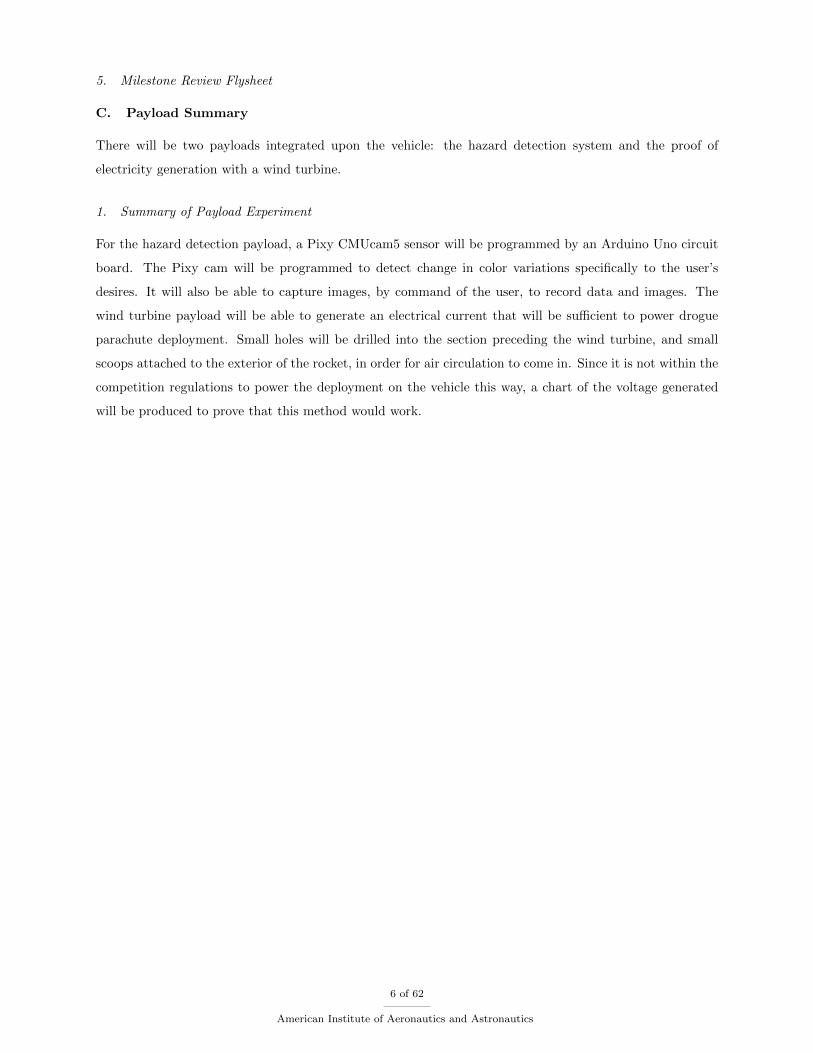
C. Payload Summary
There will be two payloads integrated upon the vehicle: the hazard detection system and the proof of
electricity generation with a wind turbine.
1. Summary of Payload Experiment
For the hazard detection payload, a Pixy CMUcam5 sensor will be programmed by an Arduino Uno circuit
board. The Pixy cam will be programmed to detect change in color variations specifically to the user’s
desires. It will also be able to capture images, by command of the user, to record data and images. The
wind turbine payload will be able to generate an electrical current that will be sufficient to power drogue
parachute deployment. Small holes will be drilled into the section preceding the wind turbine, and small
scoops attached to the exterior of the rocket, in order for air circulation to come in. Since it is not within the
competition regulations to power the deployment on the vehicle this way, a chart of the voltage generated
will be produced to prove that this method would work.
6 of 62
American Institute of Aeronautics and Astronautics
II. Changes Since Critical Design Review
A. CDR Feedback Questions and Answers
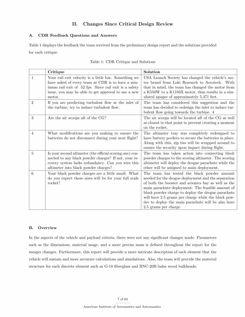
Table 1 displays the feedback the team received from the preliminary design report and the solutions provided
for each critique.
Table 1: CDR Critique and Solutions
Critique Solution
1 Your rail exit velocity is a little low. Something wehave asked of every team at CDR is to have a min-imum rail exit of 52 fps. Since rail exit is a safetyissue, you may be able to get approval to use a newmotor.
USA Launch Society has changed the vehicle’s mo-tor brand from Loki Research to Aerotech. Withthat in mind, the team has changed the motor froma K550W to a K1103X motor, thus results in a sim-ulated apogee of approximately 5,471 feet.
2 If you are predicting turbulent flow at the inlet ofthe turbine, try to induce turbulent flow.
The team has considered this suggestion and theteam has decided to redesign the inlet to induce tur-bulent flow going towards the turbine. 4
3 Are the air scoops aft of the CG? The air scoops will be located aft of the CG as wellas closest to that point to prevent creating a momenton the rocket.
4 What modifications are you making to ensure thebatteries do not disconnect during your next flight?
The altimeter tray was completely redesigned tohave battery pockets to secure the batteries in place.Along with this, zip ties will be wrapped around toensure the security upon impact during flight.
5 Is your second altimeter (the official scoring one) con-nected to any black powder charges? If not, your re-covery system lacks redundancy. Can you wire thisaltimeter into black powder charges?
The team has taken action into connecting blackpowder charges to the scoring altimeter. The scoringaltimeter will deploy the drogue parachute while theother will be assigned to main deployment.
6 Your black powder charges are a little small. Whatdo you expect these sizes will be for your full scalerocket?
The team has tested the black powder amountneeded for the drogue deployment and the separationof both the booster and avionics bay as well as themain parachute deployment. The feasible amount ofblack powder charge to deploy the drogue parachutewill have 2.5 grams per charge while the black pow-der to deploy the main parachute will be also have2.5 grams per charge.
B. Overview
In the aspects of the vehicle and payload criteria, there were not any significant changes made. Parameters
such as the dimensions, material usage, and a more precise mass is defined throughout the report for the
meager changes. Furthermore, this report will provide a more intricate description of each element that the
vehicle will sustain and more accurate calculations and simulations. Also, the team will provide the material
structure for each discrete element such as G-10 fiberglass and BNC-20B balsa wood bulkheads.
7 of 62
American Institute of Aeronautics and Astronautics
III. Vehicle Criteria
A. Design & Construction of Vehicle
The design and construction is of course a crucial part of the USLI project. In this section, the logic behind
all of the material selections and manufacturing processes will be discussed to prove that South Alabama
has produced a legitimate rocket that is worthy of flight in this competition.
1. Structural Elements
For our full-scale rocket, the team decided to use G12 fiberglass to ensure proper structural strength. During
prior sub-scale testing, the team used a cardboard body but there was occasional zippering issues and some
concern about longitudinal compressive strength during non-flight storage and transportation. The body
is composed of two body tubes. These body tubes are be attached via a 6” coupler which is permanently
attached to the avionics bay.
The rocket has four fins. These fins are located 0.75” from the base of the booster bay to ensure that the
base of the booster bay did not begin to unravel as the fin slots were cut. The fins are straight tapered with
a root chord of 6.25” and a tip chord of 3.25”. The chord lengths equate a taper ratio of 0.52 according to
Equation (1).
λ =CTCR
(1)
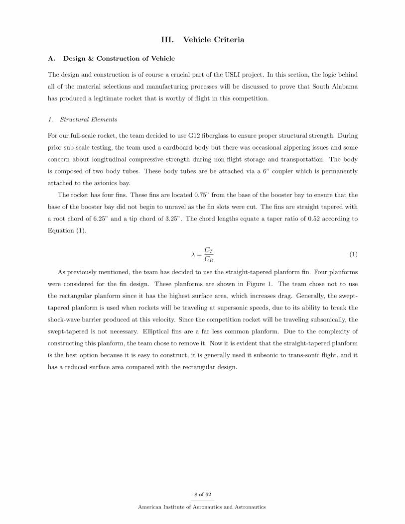
As previously mentioned, the team has decided to use the straight-tapered planform fin. Four planforms
were considered for the fin design. These planforms are shown in Figure 1. The team chose not to use
the rectangular planform since it has the highest surface area, which increases drag. Generally, the swept-
tapered planform is used when rockets will be traveling at supersonic speeds, due to its ability to break the
shock-wave barrier produced at this velocity. Since the competition rocket will be traveling subsonically, the
swept-tapered is not necessary. Elliptical fins are a far less common planform. Due to the complexity of
constructing this planform, the team chose to remove it. Now it is evident that the straight-tapered planform
is the best option because it is easy to construct, it is generally used it subsonic to trans-sonic flight, and it
has a reduced surface area compared with the rectangular design.
8 of 62
American Institute of Aeronautics and Astronautics
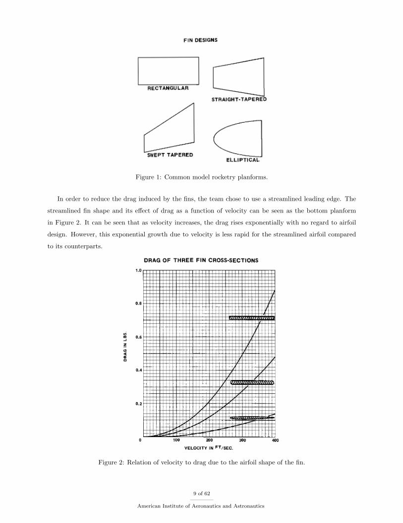
Figure 1: Common model rocketry planforms.
In order to reduce the drag induced by the fins, the team chose to use a streamlined leading edge. The
streamlined fin shape and its effect of drag as a function of velocity can be seen as the bottom planform
in Figure 2. It can be seen that as velocity increases, the drag rises exponentially with no regard to airfoil
design. However, this exponential growth due to velocity is less rapid for the streamlined airfoil compared
to its counterparts.
Figure 2: Relation of velocity to drag due to the airfoil shape of the fin.
9 of 62
American Institute of Aeronautics and Astronautics
The G10 fiberglass motor mount inside the rocket has a 2” diameter and is 1’ long. Also, it has four
centering rings. One towards the base and three on the top side of the tube evenly spaced an inch apart.
The team decided to use a pvc-like nosecone with an ogive shape. This material was used because of its
low weight and ease of use.
The altimeter bay, camera bay, and turbine bay will all be created using G10 fiberglass bays and bulk-
heads. Each bulkhead is actually composed of two round fiberglass plates. One has a slightly larger diameter
than the other to ensure that there is a tight seal on the exterior of the bulkhead. Also, the altimeter bay
is lined with metal tape to insulate the altimeters from potential unwanted noise from the transmitter.
All interior components of the rocket will be attached via half inch shock cords. The initial attachment
point for the shock cord is through a welded eye-bolt that is attached to the motor mount. The cord then
runs in between the turbine bay and the body wall until it attaches to the altimeter bay. In the middle of
the cord is a loop which attaches to the drogue parachute via a metal screw lock carabiner. There are two
other shock cords that attach to the altimeter bay. The first attaches to the camera bay. This bay lies in the
coupler of the rocket that attaches the avionics bay and the booster bay together. The other cord attaches
the top side of the altimeter bay to the nosecone as well as the main parachute. The main parachute also
connects to a loop in the shock cord with a metal screw lock carabiner.
2. Electrical Elements
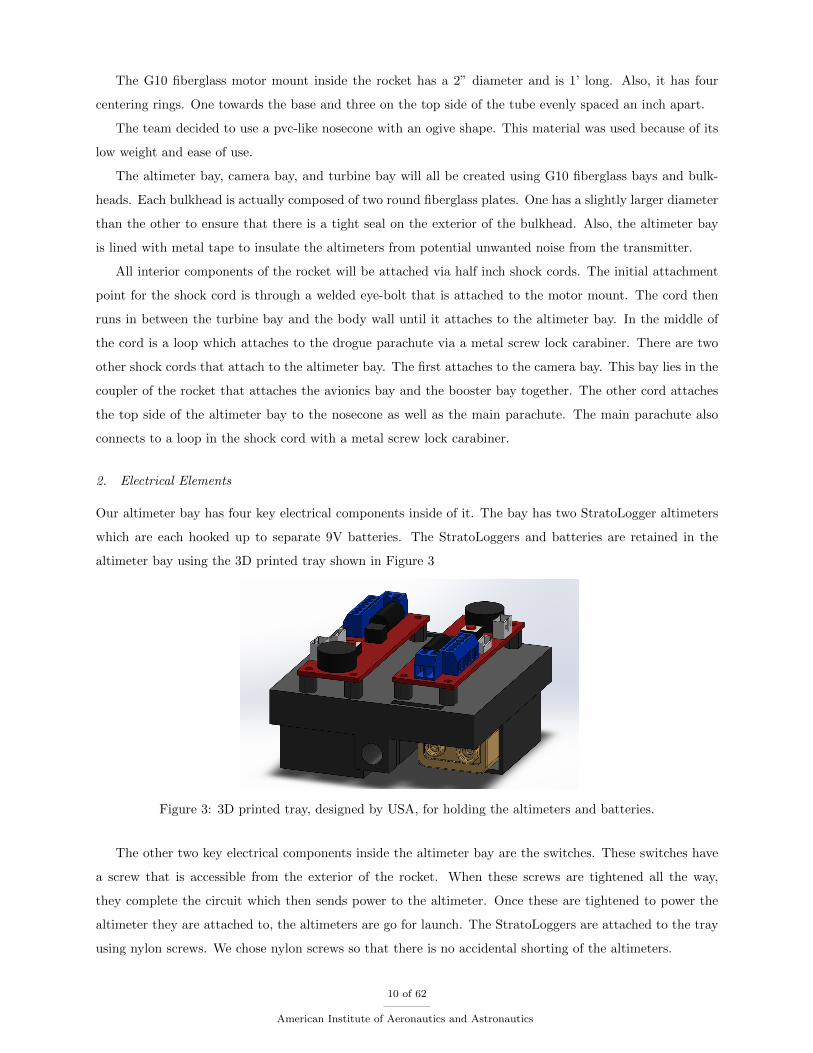
Our altimeter bay has four key electrical components inside of it. The bay has two StratoLogger altimeters
which are each hooked up to separate 9V batteries. The StratoLoggers and batteries are retained in the
altimeter bay using the 3D printed tray shown in Figure 3
Figure 3: 3D printed tray, designed by USA, for holding the altimeters and batteries.
The other two key electrical components inside the altimeter bay are the switches. These switches have
a screw that is accessible from the exterior of the rocket. When these screws are tightened all the way,
they complete the circuit which then sends power to the altimeter. Once these are tightened to power the
altimeter they are attached to, the altimeters are go for launch. The StratoLoggers are attached to the tray
using nylon screws. We chose nylon screws so that there is no accidental shorting of the altimeters.
10 of 62
American Institute of Aeronautics and Astronautics
Aside from the electronics in the altimeter bays, there are two Arduino Unos on-board. One of which
controls the PixyCam and one logs the data from the wind turbine. Both of these Arduinos and their
batteries will be attached to similar 3D printed trays. However, the tray for the camera bay will be slightly
longer to accompany the PixyCam. The PixyCam, which will survey the ground upon descent, will be linked
to one of the Arduinos in the camera bay. In order for the camera to see out of the bay during descent, the
bulkhead under the camera bay is made of polymethyl methacrylate, also known as plexiglass. This was
decided since we need this bulkhead to be clear.
The scoops on the exterior of the rocket are actually composed of a nose cone that is sliced in half and
attached to the exterior of the rocket. This will direct the airflow into two nozzles which direct the airflow
into the turbine blades.
The final electrical component will be the transmitter. The transmitter will be attached to the shock
cord near the main parachute so that it will produce solid noise after deployment. The purpose of the
transmitter is to track the rocket during flight in case visual of the rocket is lost. The selected transmitter
is a Communications Specialists, Inc. RC-HP transmitter operation on channel 437. Channel 437 runs on a
224.37 MHz frequency. The transmitter is shown below in Figure 4.
Figure 4: Communications Specialists, Inc. RC-HP transmitter used in the full-scale rocket.
B. Vehicle Assembly
Figure 17 shows the final assembly schematic of the final rocket for competition.
1. Flight Reliability Confidence
One very important reliability aspect of the rocket are the redundant black powder charges for the the
main and drogue deployments. Since we are required to have a separate altimeter for scoring, alongside
our workhorse altimeter, we decided to attach black powder charges to both altimeters. That way, if one
altimeter fails, we have redundant charges to ensure that the rocket separates, allowing the parachutes to
deploy for a safe landing. Also, we have ground tested the black powder charges to ensure that they properly
separate the shear pins and, in turn, the body itself.
In order to ensure that the camera bay deploys correctly, we decided to make the camera bay shock cord
seven feet longer that the main cord so that it stays hanging below the rocket body. The only concern is
11 of 62
American Institute of Aeronautics and Astronautics
the bay getting tangled. However, the bay will deploy slightly before the drogue parachute. Therefore, it
is designed to fall down as the parachute opens up and “pushes” up. The team had one failed full-scale
launch judging by entanglement of the camera bay. However, the parachutes did not deploy properly so the
camera bay got tangled in the main parachute shock cord. With that being said, static testing of the rocket
produced much better results, as did the second full-scale launch.
2. Static Testing Discussion
In between full-scale launches, the performed static testing due to a failed full-scale launch. In the full-
scale launch, both main and drogue parachutes deployed at apogee. As mentioned above, this caused the
camera bay to get entangled with the main parachute shock cord. We believe that the black powder charges
were loaded too heavily. When the explosions happened at apogee, the altimeter bay zippered through the
screws that it was attached to. The bay rose higher into the avionics bay due to this zippering. Then,
the built up pressure from the movement broke the nosecone shear pins, forcing the nosecone off of the
rocket. Since the nosecone was ejected, the main parachute followed as designed. Since both parachutes
deployed simultaneously, the ejection path of the camera bay was interrupted by shock cords. This launch
was considered a failure due to the improper ejections of the parachutes and the incorrect final location of
the camera bay.
As previously mentioned, due to this failed flight, the team decided to do static testing. The testing was
performed under guidance of the USA team mentor, Kendall Brent. The team first tried 2 gram charges.
The ejection worked, but it was not very powerful. It was determined that there is a possibly that the
ejection would not be capable of overcoming the speed of the air moving over the rocket body. Therefore,
the charge size was increased to 2.5 grams. This separation was very effective but not overly powerful as the
failed full-scale flight test was.
Aside from the failed full-scale flight test and the static testing performed, the team launched multiple
sub-scale flights. The primary focus of these sub-scale flights, aside from testing the rocket’s stability with
simulated masses, was to test the rocket’s stability due to the exterior air scoops on the exterior of the rocket.
As expected, the stability of the rocket was not greatly altered since the scoops are located near the center
of gravity. However, there obviously is an increase in drag.
3. Workmanship for Mission Success
The team used a combination of people to help with the construction of our rocket. There were a number
of different people who contributed to the success of the rocket. First of all, the team mentor has always
been ready to answer any questions we may have about construction ideas and processes. The other people
involved were the gentlemen in South Alabama’s machine shop. These men were always ready to help us cut
our body tubes, fins, and couplers for all of the rockets. Aside from these aspects, the rocket was entirely
constructed by members of the team. The only reason these other components were cut by the shop men
were for general student safety.
12 of 62
American Institute of Aeronautics and Astronautics
Every measurement, cut, fillet, etc. was done with extreme care and skill by the students on the USA
Launch Society. Generally, all six team members were present when any construction took place so that
there would be a system of checks and balances using multiple opinions. This way, it could be ensured that
the final result of each rocket, especially the full-scale were of the best quality.
4. Full-Scale Test Results
On February 27, South Alabama launched their first full-scale rocket. This launch was semi-successful;
however, according to NASA standards in the Student Handbook, the launch was unsuccessful. It has been
decided that the black powder charges were too heavy. Therefore, at apogee, when the drogue parachute
deployed, the charges caused such a high force that the altimeter bay zippered and moved up the rocket.
The high pressure caused from the altimeter bay sliding forward caused the nosecone to eject, deploying the
main parachute at apogee. Due to this unexpected deployment, the camera bay got wrapped in the main
parachute shock cord upon its deployment. Due to the camera bay getting tangled and the incorrect timing
of the main parachute deployment, this launch was deemed unsuccessful despite the rocket’s safe landing.
Data that was recorded by the on-board altimeters show that the rocket vehicle reached an apogee of 3507
ft.
After this launch, the team decided to ground test the black powder charges to test different ejection
charges. After testing multiple charges, the team decided to go with 2.5 gram black powder charges. This
size charge proved to eject the rocket solidly enough to break the shear pins as well as to overcome the force
that the air velocity produces on the nosecone.
On March 12th, the team traveled to Sylacauga, AL to perform an adequate full-scale flight test at the
Phoenix Missile Works launch. This flight test used a J820 motor due to the limited cloud ceiling that day
and reached an apogee of 2203 ft. This launch successfully fulfilled NASA’s USLI handbook requirements
for a full-scale because the entire flight proceeded as intended. The PixyCam / hazard detection payload
bay deployed as intended at drogue with the drogue parachute at apogee. The main parachute deployed at
700 ft. as intended and mitigated excess wind drift. The drifted distance was no more than 500 ft. from
the launch site and the vehicle was undamaged. Once recovered, the electronics and payload bays were
unharmed and data was gathered from the altimeters.
5. Safety and Failure Analysis
The team is involved with plans to evaluate and verify the vehicle’s stability and performance through
analyzing the vehicle criteria that is set by NASA and making changes to each vehicle subsystem to fit the
requirements. Once the subsystems have passed the vehicle verification, the team will go into further detail
by testing each subsystem to success. A table has been created to outline each vehicle requirement and its
assessment to the design ??.
The stability and drag assessment is provided in the following sections; moreover, a buckling analysis
has been performed to ensure the safety of Team South Alabama’s rocket vehicle. As aforementioned in
13 of 62
American Institute of Aeronautics and Astronautics
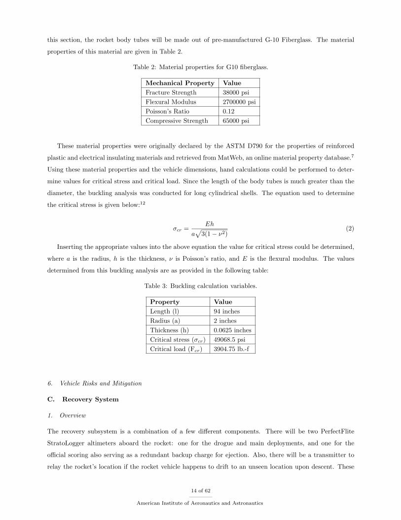
this section, the rocket body tubes will be made out of pre-manufactured G-10 Fiberglass. The material
properties of this material are given in Table 2.
Table 2: Material properties for G10 fiberglass.
Mechanical Property Value
Fracture Strength 38000 psi
Flexural Modulus 2700000 psi
Poisson’s Ratio 0.12
Compressive Strength 65000 psi
These material properties were originally declared by the ASTM D790 for the properties of reinforced
plastic and electrical insulating materials and retrieved from MatWeb, an online material property database.7
Using these material properties and the vehicle dimensions, hand calculations could be performed to deter-
mine values for critical stress and critical load. Since the length of the body tubes is much greater than the
diameter, the buckling analysis was conducted for long cylindrical shells. The equation used to determine
the critical stress is given below:12
σcr =Eh
a√
3(1− ν2)(2)
Inserting the appropriate values into the above equation the value for critical stress could be determined,
where a is the radius, h is the thickness, ν is Poisson’s ratio, and E is the flexural modulus. The values
determined from this buckling analysis are as provided in the following table:
Table 3: Buckling calculation variables.
Property Value
Length (l) 94 inches
Radius (a) 2 inches
Thickness (h) 0.0625 inches
Critical stress (σcr) 49068.5 psi
Critical load (Fcr) 3904.75 lb.-f
6. Vehicle Risks and Mitigation
C. Recovery System
1. Overview
The recovery subsystem is a combination of a few different components. There will be two PerfectFlite
StratoLogger altimeters aboard the rocket: one for the drogue and main deployments, and one for the
official scoring also serving as a redundant backup charge for ejection. Also, there will be a transmitter to
relay the rocket’s location if the rocket vehicle happens to drift to an unseen location upon descent. These
14 of 62
American Institute of Aeronautics and Astronautics
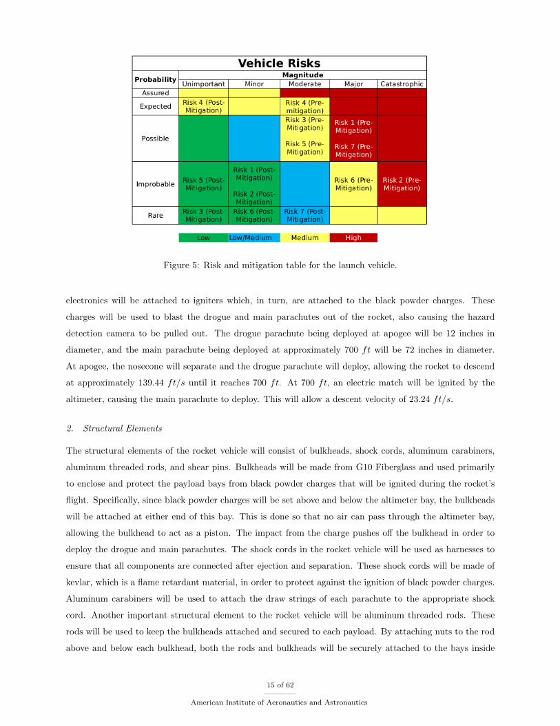
Figure 5: Risk and mitigation table for the launch vehicle.
electronics will be attached to igniters which, in turn, are attached to the black powder charges. These
charges will be used to blast the drogue and main parachutes out of the rocket, also causing the hazard
detection camera to be pulled out. The drogue parachute being deployed at apogee will be 12 inches in
diameter, and the main parachute being deployed at approximately 700 ft will be 72 inches in diameter.
At apogee, the nosecone will separate and the drogue parachute will deploy, allowing the rocket to descend
at approximately 139.44 ft/s until it reaches 700 ft. At 700 ft, an electric match will be ignited by the
altimeter, causing the main parachute to deploy. This will allow a descent velocity of 23.24 ft/s.
2. Structural Elements
The structural elements of the rocket vehicle will consist of bulkheads, shock cords, aluminum carabiners,
aluminum threaded rods, and shear pins. Bulkheads will be made from G10 Fiberglass and used primarily
to enclose and protect the payload bays from black powder charges that will be ignited during the rocket’s
flight. Specifically, since black powder charges will be set above and below the altimeter bay, the bulkheads
will be attached at either end of this bay. This is done so that no air can pass through the altimeter bay,
allowing the bulkhead to act as a piston. The impact from the charge pushes off the bulkhead in order to
deploy the drogue and main parachutes. The shock cords in the rocket vehicle will be used as harnesses to
ensure that all components are connected after ejection and separation. These shock cords will be made of
kevlar, which is a flame retardant material, in order to protect against the ignition of black powder charges.
Aluminum carabiners will be used to attach the draw strings of each parachute to the appropriate shock
cord. Another important structural element to the rocket vehicle will be aluminum threaded rods. These
rods will be used to keep the bulkheads attached and secured to each payload. By attaching nuts to the rod
above and below each bulkhead, both the rods and bulkheads will be securely attached to the bays inside
15 of 62
American Institute of Aeronautics and Astronautics
the rocket. U-bolts will also be attached to the bulkheads of each bay in order for the shock cord to be tied
on appropriately. Furthermore, shear pins will be inserted externally through the attachment of the avionics
bay and nosecone to ensure connection of the two components. At apogee and ejection, these shear pins will
shear and break causing the two components to separate and the drogue parachute to deploy.
3. Electrical Elements
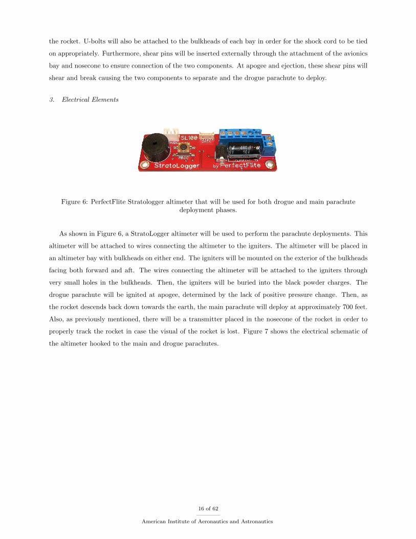
Figure 6: PerfectFlite Stratologger altimeter that will be used for both drogue and main parachutedeployment phases.
As shown in Figure 6, a StratoLogger altimeter will be used to perform the parachute deployments. This
altimeter will be attached to wires connecting the altimeter to the igniters. The altimeter will be placed in
an altimeter bay with bulkheads on either end. The igniters will be mounted on the exterior of the bulkheads
facing both forward and aft. The wires connecting the altimeter will be attached to the igniters through
very small holes in the bulkheads. Then, the igniters will be buried into the black powder charges. The
drogue parachute will be ignited at apogee, determined by the lack of positive pressure change. Then, as
the rocket descends back down towards the earth, the main parachute will deploy at approximately 700 feet.
Also, as previously mentioned, there will be a transmitter placed in the nosecone of the rocket in order to
properly track the rocket in case the visual of the rocket is lost. Figure 7 shows the electrical schematic of
the altimeter hooked to the main and drogue parachutes.
16 of 62
American Institute of Aeronautics and Astronautics
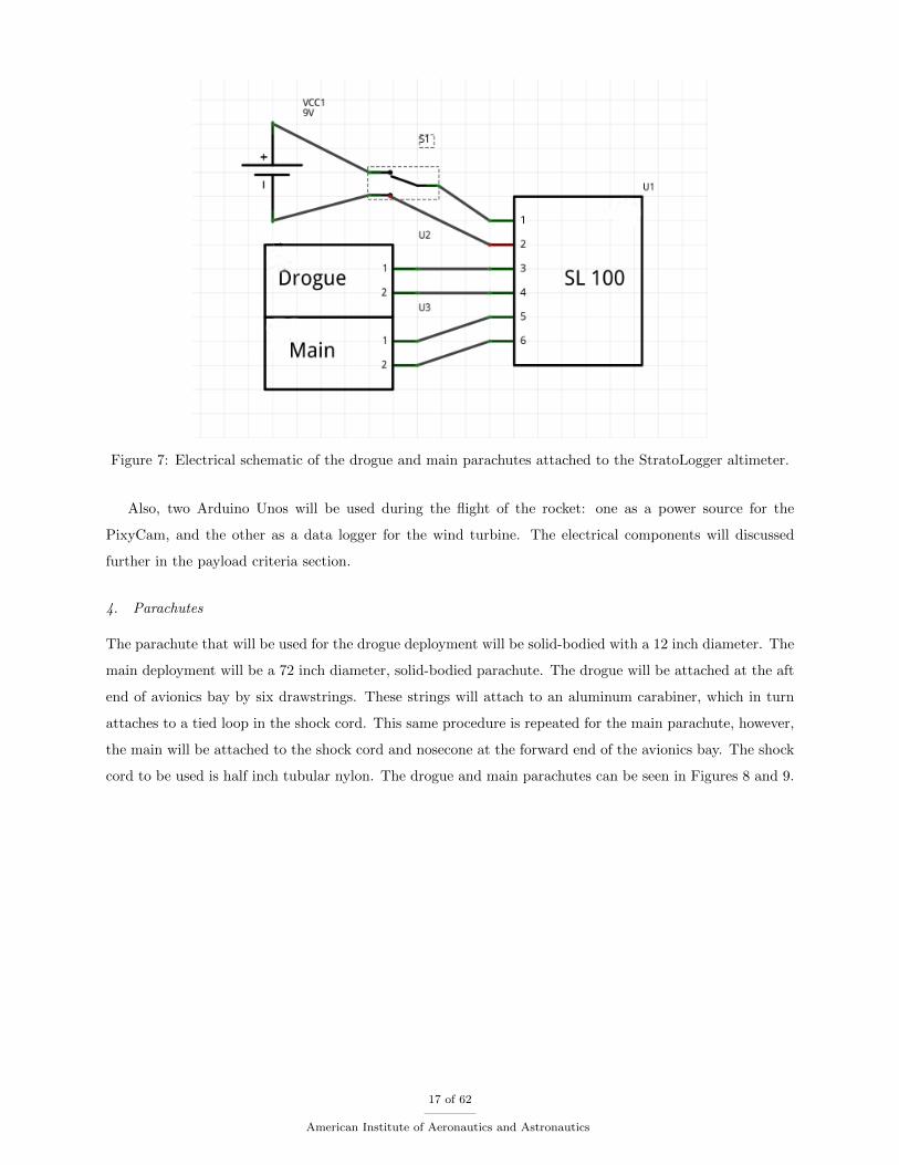
Figure 7: Electrical schematic of the drogue and main parachutes attached to the StratoLogger altimeter.
Also, two Arduino Unos will be used during the flight of the rocket: one as a power source for the
PixyCam, and the other as a data logger for the wind turbine. The electrical components will discussed
further in the payload criteria section.
4. Parachutes
The parachute that will be used for the drogue deployment will be solid-bodied with a 12 inch diameter. The
main deployment will be a 72 inch diameter, solid-bodied parachute. The drogue will be attached at the aft
end of avionics bay by six drawstrings. These strings will attach to an aluminum carabiner, which in turn
attaches to a tied loop in the shock cord. This same procedure is repeated for the main parachute, however,
the main will be attached to the shock cord and nosecone at the forward end of the avionics bay. The shock
cord to be used is half inch tubular nylon. The drogue and main parachutes can be seen in Figures 8 and 9.
17 of 62
American Institute of Aeronautics and Astronautics
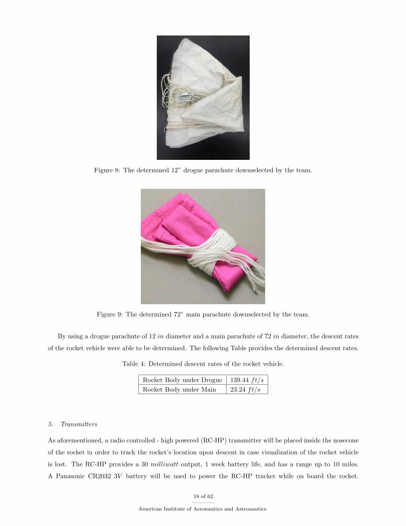
Figure 8: The determined 12” drogue parachute downselected by the team.
Figure 9: The determined 72” main parachute downselected by the team.
By using a drogue parachute of 12 in diameter and a main parachute of 72 in diameter, the descent rates
of the rocket vehicle were able to be determined. The following Table provides the determined descent rates.
Table 4: Determined descent rates of the rocket vehicle.
Rocket Body under Drogue 139.44 ft/s
Rocket Body under Main 23.24 ft/s
5. Transmitters
As aforementioned, a radio controlled - high powered (RC-HP) transmitter will be placed inside the nosecone
of the rocket in order to track the rocket’s location upon descent in case visualization of the rocket vehicle
is lost. The RC-HP provides a 30 milliwatt output, 1 week battery life, and has a range up to 10 miles.
A Panasonic CR2032 3V battery will be used to power the RC-HP tracker while on board the rocket.
18 of 62
American Institute of Aeronautics and Astronautics
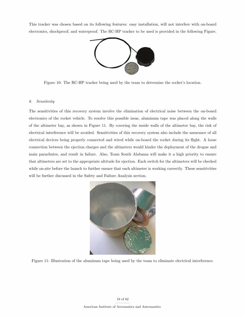
This tracker was chosen based on its following features: easy installation, will not interfere with on-board
electronics, shockproof, and waterproof. The RC-HP tracker to be used is provided in the following Figure.
Figure 10: The RC-HP tracker being used by the team to determine the rocket’s location.
6. Sensitivity
The sensitivities of this recovery system involve the elimination of electrical noise between the on-board
electronics of the rocket vehicle. To resolve this possible issue, aluminum tape was placed along the walls
of the altimeter bay, as shown in Figure 11. By covering the inside walls of the altimeter bay, the risk of
electrical interference will be avoided. Sensitivities of this recovery system also include the assurance of all
electrical devices being properly connected and wired while on-board the rocket during its flight. A loose
connection between the ejection charges and the altimeters would hinder the deployment of the drogue and
main parachutes, and result in failure. Also, Team South Alabama will make it a high priority to ensure
that altimeters are set to the appropriate altitude for ejection. Each switch for the altimeters will be checked
while on-site before the launch to further ensure that each altimeter is working correctly. These sensitivities
will be further discussed in the Safety and Failure Analysis section.
Figure 11: Illustration of the aluminum tape being used by the team to eliminate electrical interference.
19 of 62
American Institute of Aeronautics and Astronautics
7. Deployment Process
The deployment process of the rocket vehicle will occur as follows:
• Upon attaining apogee, a black powder charge will ignite to separate the avionics bay and booster bay.
• If, by chance, the first black powder charge does not ignite, a second black powder charge will be set
to fire one second after the first to ensure deployment of the drogue parachute.
• Avionics Bay and Booster Bay separate and drogue parachute deploys.
• Hazard Detection PixyCam payload is pulled out by being attached to the shock cord that is attached
to the drogue.
• Rocket descends to approximately 700 ft.
• Black powder charge ignites to separate the nosecone from the avionics bay.
• If, by chance, the first black powder charge does not ignite, a second black powder charge will be set
to fire one second after the first to ensure deployment of the main parachute.
• Main parachute deploys while remaining attached to the shock cord and avionics bay.
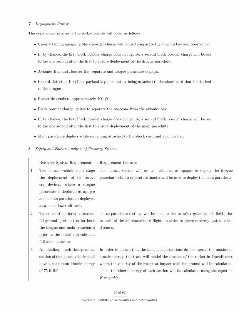
8. Safety and Failure Analysis of Recovery System
Recovery System Requirement Requirement Features
1 The launch vehicle shall stage
the deployment of its recov-
ery devices, where a drogue
parachute is deployed at apogee
and a main parachute is deployed
at a much lower altitude.
The launch vehicle will use an altimeter at apogee to deploy the drogue
parachute while a separate altimeter will be used to deploy the main parachute.
2 Teams must perform a success-
ful ground ejection test for both
the drogue and main parachutes
prior to the initial subscale and
full-scale launches.
These parachute testings will be done at the team’s regular launch field prior
to both of the aforementioned flights in order to prove recovery system effec-
tiveness.
3 At landing, each independent
section of the launch vehicle shall
have a maximum kinetic energy
of 75 ft-lbf.
In order to ensure that the independent sections do not exceed the maximum
kinetic energy, the team will model the descent of the rocket in OpenRocket
where the velocity of the rocket at impact with the ground will be calculated.
Then, the kinetic energy of each section will be calculated using the equation
E = 12mV
2.
20 of 62
American Institute of Aeronautics and Astronautics
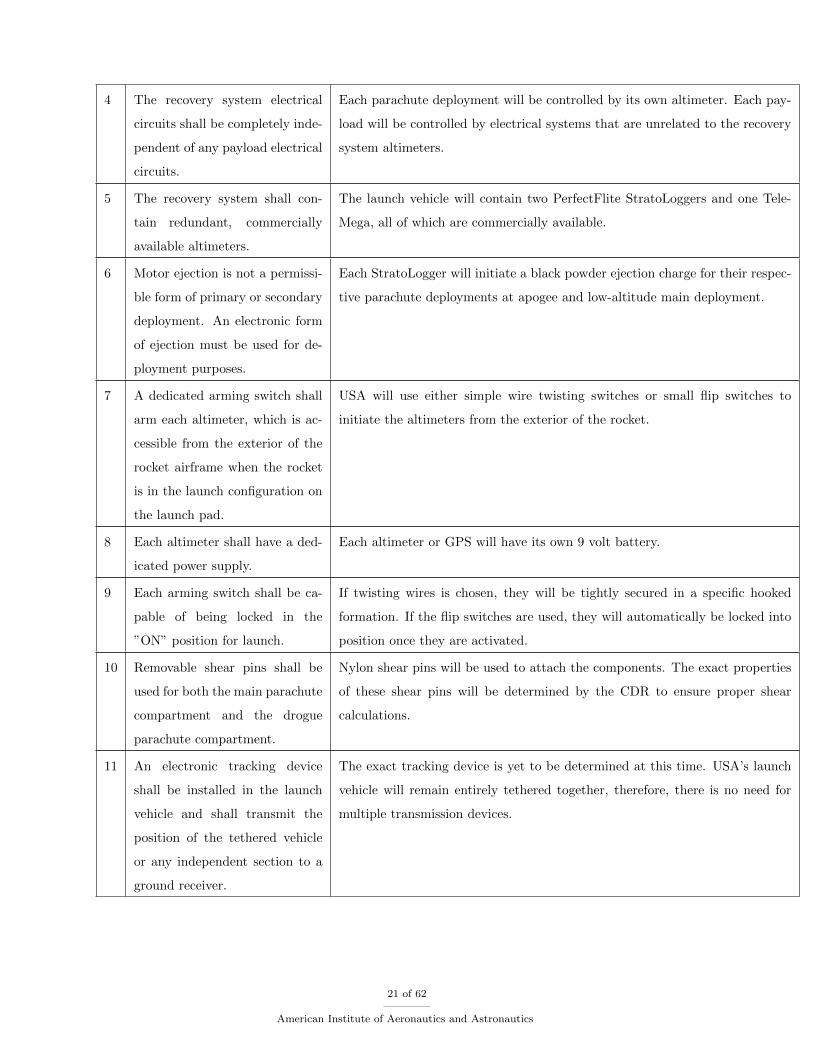
4 The recovery system electrical
circuits shall be completely inde-
pendent of any payload electrical
circuits.
Each parachute deployment will be controlled by its own altimeter. Each pay-
load will be controlled by electrical systems that are unrelated to the recovery
system altimeters.
5 The recovery system shall con-
tain redundant, commercially
available altimeters.
The launch vehicle will contain two PerfectFlite StratoLoggers and one Tele-
Mega, all of which are commercially available.
6 Motor ejection is not a permissi-
ble form of primary or secondary
deployment. An electronic form
of ejection must be used for de-
ployment purposes.
Each StratoLogger will initiate a black powder ejection charge for their respec-
tive parachute deployments at apogee and low-altitude main deployment.
7 A dedicated arming switch shall
arm each altimeter, which is ac-
cessible from the exterior of the
rocket airframe when the rocket
is in the launch configuration on
the launch pad.
USA will use either simple wire twisting switches or small flip switches to
initiate the altimeters from the exterior of the rocket.
8 Each altimeter shall have a ded-
icated power supply.
Each altimeter or GPS will have its own 9 volt battery.
9 Each arming switch shall be ca-
pable of being locked in the
”ON” position for launch.
If twisting wires is chosen, they will be tightly secured in a specific hooked
formation. If the flip switches are used, they will automatically be locked into
position once they are activated.
10 Removable shear pins shall be
used for both the main parachute
compartment and the drogue
parachute compartment.
Nylon shear pins will be used to attach the components. The exact properties
of these shear pins will be determined by the CDR to ensure proper shear
calculations.
11 An electronic tracking device
shall be installed in the launch
vehicle and shall transmit the
position of the tethered vehicle
or any independent section to a
ground receiver.
The exact tracking device is yet to be determined at this time. USA’s launch
vehicle will remain entirely tethered together, therefore, there is no need for
multiple transmission devices.
21 of 62
American Institute of Aeronautics and Astronautics
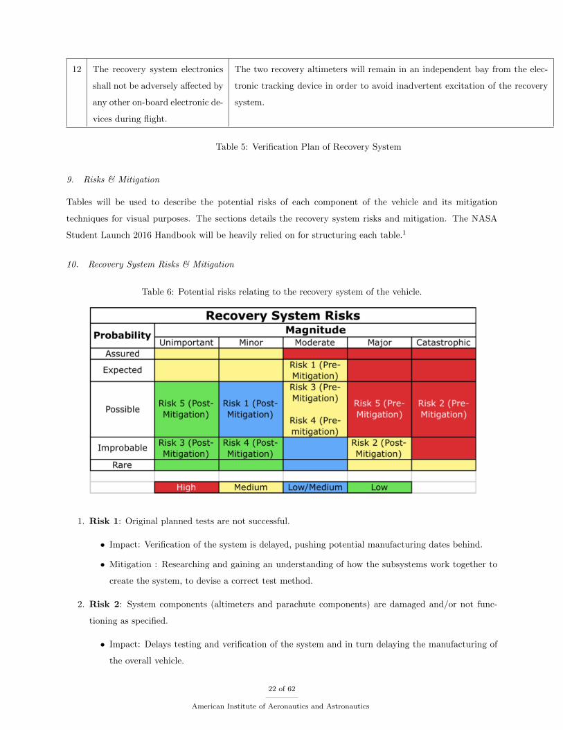
12 The recovery system electronics
shall not be adversely affected by
any other on-board electronic de-
vices during flight.
The two recovery altimeters will remain in an independent bay from the elec-
tronic tracking device in order to avoid inadvertent excitation of the recovery
system.
Table 5: Verification Plan of Recovery System
9. Risks & Mitigation
Tables will be used to describe the potential risks of each component of the vehicle and its mitigation
techniques for visual purposes. The sections details the recovery system risks and mitigation. The NASA
Student Launch 2016 Handbook will be heavily relied on for structuring each table.1
10. Recovery System Risks & Mitigation
Table 6: Potential risks relating to the recovery system of the vehicle.
1. Risk 1: Original planned tests are not successful.
• Impact: Verification of the system is delayed, pushing potential manufacturing dates behind.
• Mitigation : Researching and gaining an understanding of how the subsystems work together to
create the system, to devise a correct test method.
2. Risk 2: System components (altimeters and parachute components) are damaged and/or not func-
tioning as specified.
• Impact: Delays testing and verification of the system and in turn delaying the manufacturing of
the overall vehicle.
22 of 62
American Institute of Aeronautics and Astronautics
• Mitigation: Pre-test briefing specifically covering the handling of the sensitive components. Also,
ordering excess components as a safety net since there tends to be error.
3. Risk 3: Parachute materials are not readily available and need to be ordered.
• Impact: May delay testing plans and/or manufacturing process.
• Mitigation: The team will buy excess amounts of material needed to manufacture the parachutes
in order to hinder the risk from happening.
4. Risk 4: The down selected altimeters are on back order.
• Impact: May delay testing of the electronics, which will create a setback in the team’s specific
benchmarks.
• Mitigation: The team may order multiple of the components or if too close to very important
milestones, the team may select another altimeter that was considered.
5. Risk 5: The altimeters are damaged upon delivery due to poor handling and/or poor packaging.
• Impact: Testing of the recovery system will be delayed in turn pushing important benchmarks
further behind.
• Mitigation: An alternate altimeter that was originally considered will be used.
D. Mission Performance Predictions
USA Launch Society’s mission performance criteria is to achieve the following events:
• Achieve a maximum altitude of 5,280 feet (1 mile), or as close as possible. Note: A maximum altitude
of 5,280 feet is chosen rather than a minimum since the flight score penalty for overshooting the target
altitude is twice as much as undershooting.
• Successfully eject the top body tube and deploy the drogue parachute at apogee.
• Successfully eject the nose cone and deploy the main parachute within the range of 900 to 700 feet as
the rocket is descending.
• Achieve a safe landing and recovery of the rocket with intact parts to be reused.
23 of 62
American Institute of Aeronautics and Astronautics
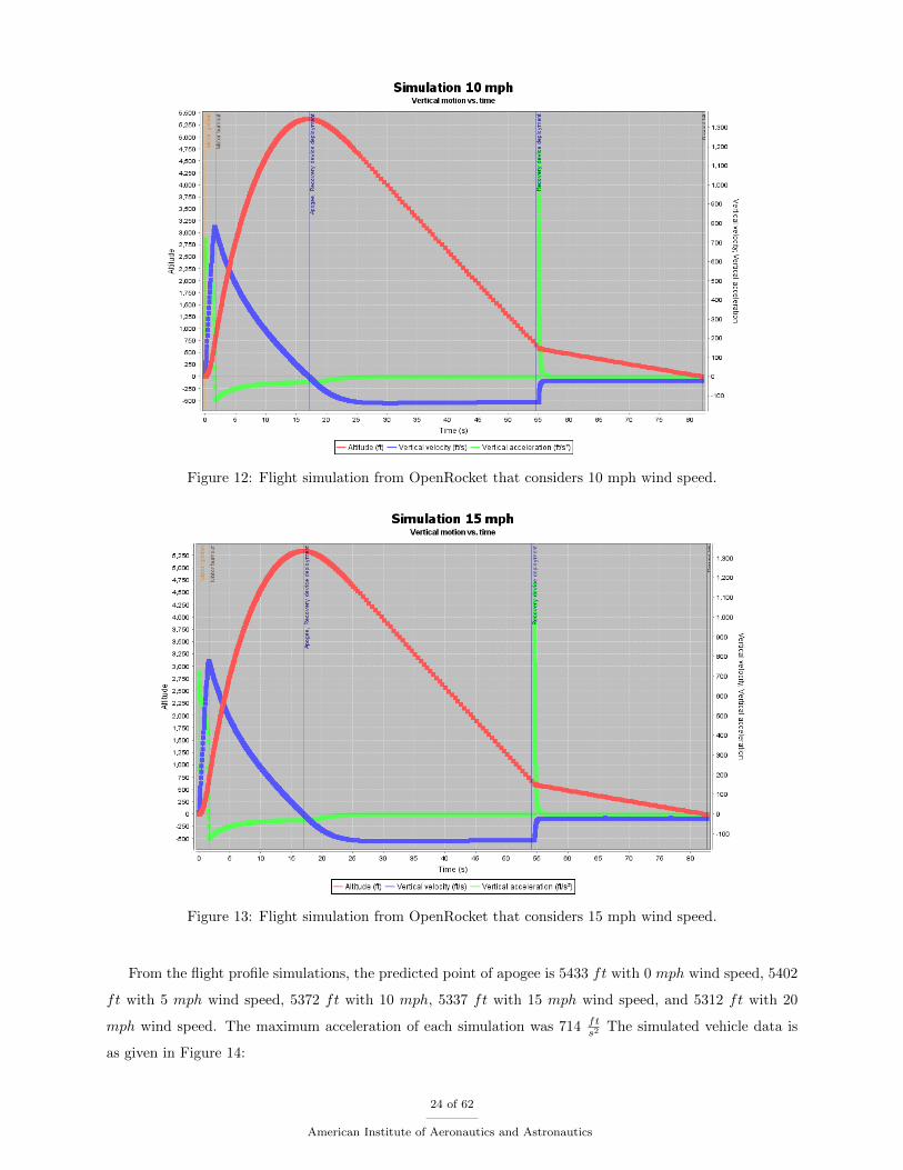
Figure 12: Flight simulation from OpenRocket that considers 10 mph wind speed.
Figure 13: Flight simulation from OpenRocket that considers 15 mph wind speed.
From the flight profile simulations, the predicted point of apogee is 5433 ft with 0 mph wind speed, 5402
ft with 5 mph wind speed, 5372 ft with 10 mph, 5337 ft with 15 mph wind speed, and 5312 ft with 20
mph wind speed. The maximum acceleration of each simulation was 714 fts2 The simulated vehicle data is
as given in Figure 14:
24 of 62
American Institute of Aeronautics and Astronautics
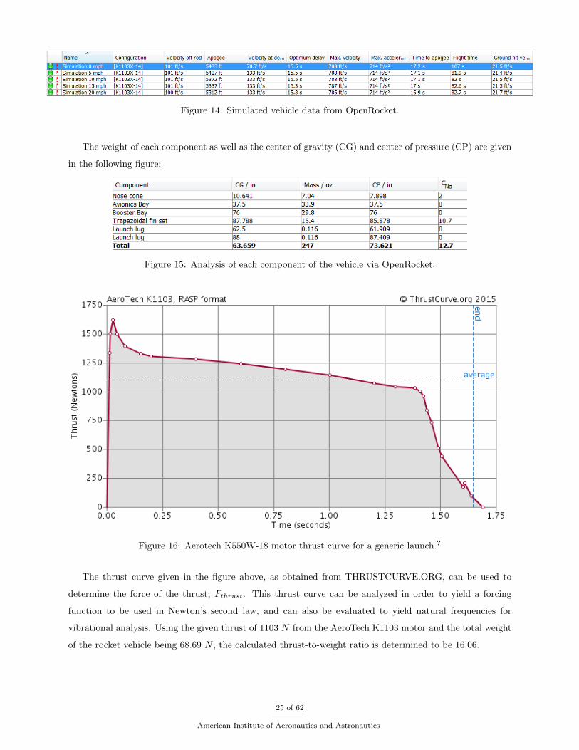
Figure 14: Simulated vehicle data from OpenRocket.
The weight of each component as well as the center of gravity (CG) and center of pressure (CP) are given
in the following figure:
Figure 15: Analysis of each component of the vehicle via OpenRocket.
Figure 16: Aerotech K550W-18 motor thrust curve for a generic launch.?
The thrust curve given in the figure above, as obtained from THRUSTCURVE.ORG, can be used to
determine the force of the thrust, Fthrust. This thrust curve can be analyzed in order to yield a forcing
function to be used in Newton’s second law, and can also be evaluated to yield natural frequencies for
vibrational analysis. Using the given thrust of 1103 N from the AeroTech K1103 motor and the total weight
of the rocket vehicle being 68.69 N , the calculated thrust-to-weight ratio is determined to be 16.06.
25 of 62
American Institute of Aeronautics and Astronautics
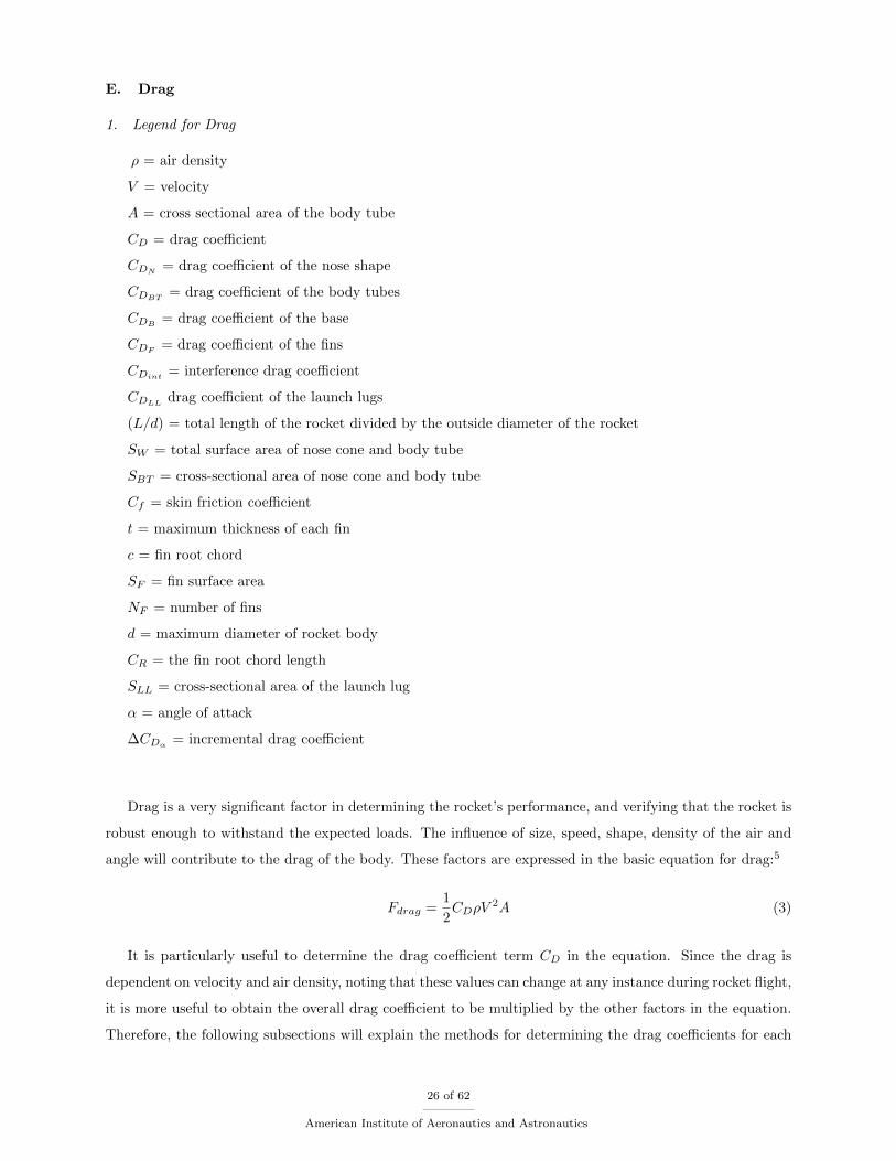
E. Drag
1. Legend for Drag
ρ = air density
V = velocity
A = cross sectional area of the body tube
CD = drag coefficient
CDN = drag coefficient of the nose shape
CDBT = drag coefficient of the body tubes
CDB = drag coefficient of the base
CDF = drag coefficient of the fins
CDint = interference drag coefficient
CDLL drag coefficient of the launch lugs
(L/d) = total length of the rocket divided by the outside diameter of the rocket
SW = total surface area of nose cone and body tube
SBT = cross-sectional area of nose cone and body tube
Cf = skin friction coefficient
t = maximum thickness of each fin
c = fin root chord
SF = fin surface area
NF = number of fins
d = maximum diameter of rocket body
CR = the fin root chord length
SLL = cross-sectional area of the launch lug
α = angle of attack
∆CDα = incremental drag coefficient
Drag is a very significant factor in determining the rocket’s performance, and verifying that the rocket is
robust enough to withstand the expected loads. The influence of size, speed, shape, density of the air and
angle will contribute to the drag of the body. These factors are expressed in the basic equation for drag:5
Fdrag =1
2CDρV
2A (3)
It is particularly useful to determine the drag coefficient term CD in the equation. Since the drag is
dependent on velocity and air density, noting that these values can change at any instance during rocket flight,
it is more useful to obtain the overall drag coefficient to be multiplied by the other factors in the equation.
Therefore, the following subsections will explain the methods for determining the drag coefficients for each
26 of 62
American Institute of Aeronautics and Astronautics

component of the rocket. The overall drag coefficient for a model rocket is expressed as the summation of
each components as follows:5
CDO = CDN + CDBT + CDB + CDF + CDint + CDLL (4)
The subscript, O, in CDO is used to represent the drag of the rocket when it is moving directly into the
wind. This is also known as having a zero angle of attack relative to the wind. This will give the lowest
possible value for the drag coefficient, thus resulting in the lowest possible value for the drag of the rocket. It
is good to get the minimum drag first since this gives a goal to try to attain. However, since rockets operate
at various angles of attack, it is important to determine the impact this produces on the rocket’s drag.5 The
current analysis will consist of focusing on determining the drag coefficients at zero angle of attack. This
will serve as the starting point for obtaining an overall drag coefficient. Once a sufficient value has been
obtained for the zero angle of attack case, various angles of attack will then be incorporated to result in a
better approximation.
2. Body Tubes
Extensive tests have been performed through the study of aerodynamics to provide a useful formula to
determine the drag coefficient of the body tube with the nose cone included:5
CDN + CDBT = 1.02Cf
[1 +
1.5
(L/d)1.5
]SWSBT
(5)
The skin friction Cf is dependent on the Reynolds number.The Reynolds number will determine if the
air boundary layer flowing over the rockets surface is laminar or turbulent. For air flows, when the value for
Reynolds number is determined to be less than 100,000, the boundary layer is considered laminar. When
the value is determined to be greater than or equal to 1,000,000, the value is called the critical Reynolds
number (Recr) and the boundary layer is considered to be turbulent. If the value is in between these limits
(100,000 and 1,000,000), it becomes difficult to accurately predict if the flow is laminar or turbulent. This
is called the transition zone.5 To determine the Reynolds number, the following equation can be used:
Re =ρV l
µ(6)
Once the Reynolds number is determined, three approximate skin friction coefficients will be obtained for
three different cases. The first case will be for a fully laminar flow. The second case will be for a boundary
layer that begins laminar and then transitions into a turbulent boundary layer once the critical Reynolds
number is reached. The third case will be for a boundary layer that is fully turbulent. The average skin
friction coefficient equation that will be used for fully laminar flow is defined as:11
Cf =1.33√Re
(7)
27 of 62
American Institute of Aeronautics and Astronautics
The average skin friction coefficient equation that will be used for the laminar flow transitioning into
turbulent flow is as follows:3
Cftran =0.523
[ln(0.06Re)]2− 1520
Re(8)
The average skin friction coefficient equation that will be used for the fully turbulent flow is given as:11
Cf =0.074
Re0.2(9)
Another significant location on the body tube to consider is at the base (rear of rocket). The drag at the
base is due to the pressure unbalance from the separation of the air flow at the end of the rocket. The base
drag coefficient can be approximated by using the following equation:5
CDB =0.029√
CDN + CDBT(10)
3. Interference Drag
The interference drag is the result of the air passing over the body tube interacting with the air flowing over
the fins. Sharp corners where the fins meet will increase interference causing a higher drag while smooth,
filleted corners decrease interference causing lower drag.5 The interference drag coefficient can be determine
from the following equation:
CDint = CDOFCRSBT
d
2xnumberoffins (11)
4. Launch Lug Drag
A method that can be used to determine a value for launch lug drag is to obtain an upper limit on the drag
coefficient. This is done by establishing the worse case scenario for a launch lug. For example, if cylindrical
launch lugs are used, the worse case would be to have a solid disc standing at a right angle to the flow. The
drag coefficient for a disc at right angles to the flow is around 1.2.5 By using the following equation, the
upper limit launch lug coefficient can be determined.
CDLLup = 1.2SLLSBT
(12)
Since the launch lugs for this example are cylindrical and not solid flat discs, they will have two surface
areas that experience skin friction drags. The surface area for the cylinder is composed of the inner and
outer surfaces.
SLLw = πdoutl + πdinl (13)
28 of 62
American Institute of Aeronautics and Astronautics
The surface area, SLLw , will then be incorporated into the upper limit launch lug coefficient equation to
obtain the equation for the upper limit coefficient of launch lugs which is written as the follows:5
CDLL =1.2SLL + SLL
SBT(14)
This method can also be performed for non cylindrical shaped launch lugs by using the cross-sectional
area and surface areas associated with the different shape.
5. Stability
Stability is a significant factor that needs to be considered when designing rockets. It is a must that a rocket
be stable in order to achieve the best and safest flight possible. The first rule to be followed in achieving
stability is that the rocket’s center of pressure must be aft its center of gravity. The distance between the
center of gravity and center of pressure is the static margin, also known as the ”caliber of stability.” The
center of gravity should be at least one body tube diameter fore the center of pressure.4
In 1966, James S. Barrowman and Judith A. Barrowman presented their research and development
project titled, The Theoretical Prediction of the Center of Pressure. The authors successfully derived and
simplified the resulting subsonic theoretical center of pressure equations for general rocket configurations.
The equations found in Barrowmans’ project has provided an accurate method for calculating the center of
pressure for subsonic model rockets and became the staple method for model rocketeers. In recent years,
these equations have been integrated into computer software programs such as OPENROCKET to allow a
quick and easy center of pressure calculation. As the designer changes rocket configurations, the computer
software simultaneously computes the center of pressure and stability margin. Therefore, to simplify the
center of pressure calculation, USA Launch Society will be using the computer program OPENROCKET.
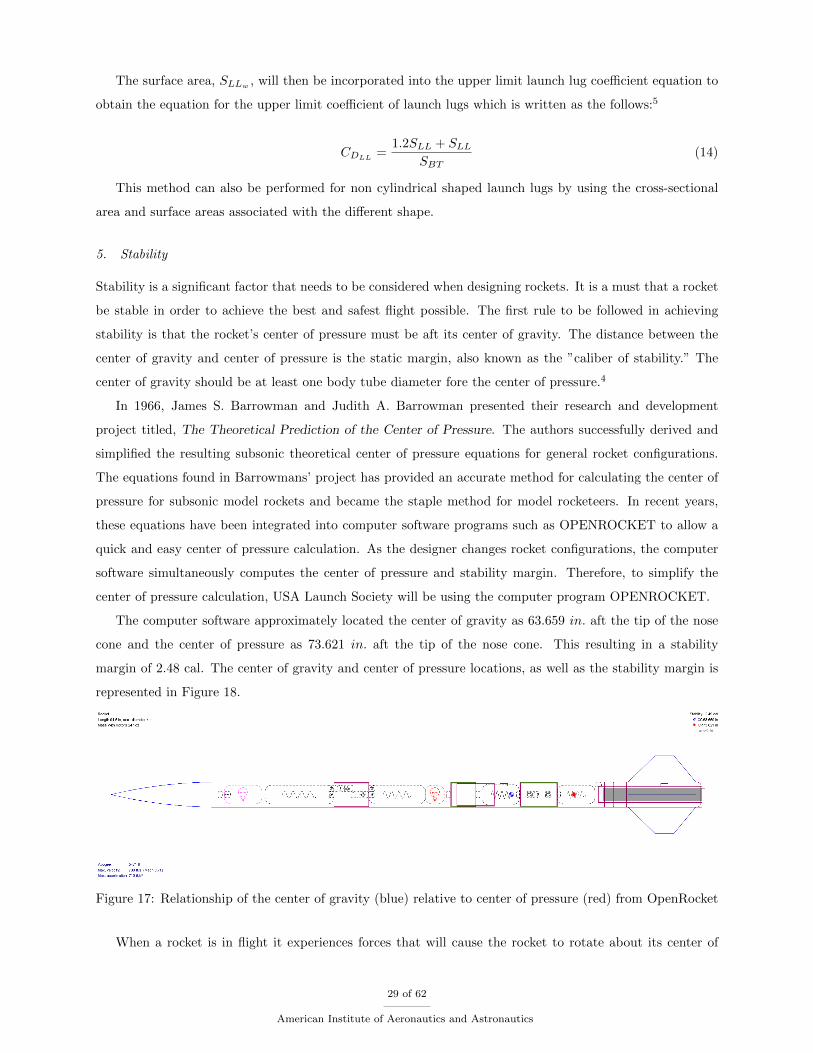
The computer software approximately located the center of gravity as 63.659 in. aft the tip of the nose
cone and the center of pressure as 73.621 in. aft the tip of the nose cone. This resulting in a stability
margin of 2.48 cal. The center of gravity and center of pressure locations, as well as the stability margin is
represented in Figure 18.
Figure 17: Relationship of the center of gravity (blue) relative to center of pressure (red) from OpenRocket
When a rocket is in flight it experiences forces that will cause the rocket to rotate about its center of
29 of 62
American Institute of Aeronautics and Astronautics
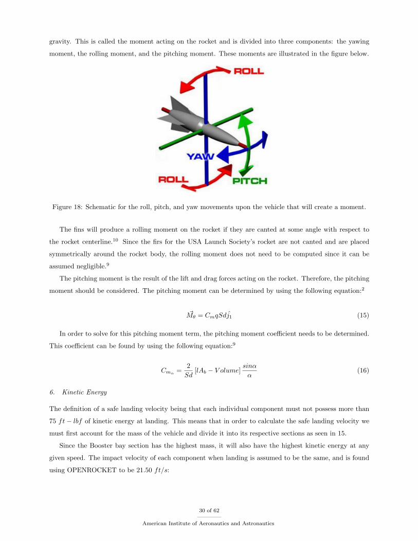
gravity. This is called the moment acting on the rocket and is divided into three components: the yawing
moment, the rolling moment, and the pitching moment. These moments are illustrated in the figure below.
Figure 18: Schematic for the roll, pitch, and yaw movements upon the vehicle that will create a moment.
The fins will produce a rolling moment on the rocket if they are canted at some angle with respect to
the rocket centerline.10 Since the firs for the USA Launch Society’s rocket are not canted and are placed
symmetrically around the rocket body, the rolling moment does not need to be computed since it can be
assumed negligible.9
The pitching moment is the result of the lift and drag forces acting on the rocket. Therefore, the pitching
moment should be considered. The pitching moment can be determined by using the following equation:2
~Mθ = CmqSdj1 (15)
In order to solve for this pitching moment term, the pitching moment coefficient needs to be determined.
This coefficient can be found by using the following equation:9
Cmα =2
Sd[lAb − V olume]
sinα
α(16)
6. Kinetic Energy
The definition of a safe landing velocity being that each individual component must not possess more than
75 ft− lbf of kinetic energy at landing. This means that in order to calculate the safe landing velocity we
must first account for the mass of the vehicle and divide it into its respective sections as seen in 15.
Since the Booster bay section has the highest mass, it will also have the highest kinetic energy at any
given speed. The impact velocity of each component when landing is assumed to be the same, and is found
using OPENROCKET to be 21.50 ft/s:
30 of 62
American Institute of Aeronautics and Astronautics
Ek =1
2mV 2 (17)
By inserting the determined values, the kinetic energy of each main component can be found using the
above equation. Using the equation for kinetic energy, and substituting the mass of each section and the
ground impact velocity of 21.50 ft/s, the kinetic energies are as follows: Nosecone = 3.90 ft− lbf , Avionics
= 40.54 ft− lbf , and the Booster = 66.45 ft− lbf .
To determine the kinetic energy of each component at the start of the launch sequence coming off the
rail, the rail exit velocity of 101.00 ft/s given from OPENROCKET is used. Inserting this value of velocity
and the provided mass of each section into the kinetic energy equation, the kinetic energies are as follows:
Nosecone = 86.10 ft− lbf , Avionics = 894.63 ft− lbf , and the Booster = 1466.39 ft− lbf .
The kinetic energy of each component at the deployment of the main parachute is determined using the
velocity at deployment of 133 ft/s given from OPENROCKET, and the appropriate mass of each component.
Inserting these values into the kinetic energy equation provides the following kinetic energies of each main
component: Nosecone = 149.30 ft− lbf , Avionics = 1551.32 ft− lbf , and the Booster = 2542.79 ft− lbf .
7. Wind Drift
For preliminary determinations of wind drift, a very simple mathematical model will be used. In this
model, the parachute is assumed to have no inherent horizontal motion, which in the real world is false, but
the assumption allows for basic analysis of wind drift scenarios. As the recovery section progresses, these
calculations will become more precise and account for more variables.
These calculations will only consider the parachutes drifting after the deployment of the main parachute,
and while it ignores a large amount of potential drift, it allows for more straightforward estimations. The
speed of descent is found using the following equation:8
V =
√8mg
πρCDD2(18)
In the above equation, m is 0.45067 slugs, g is gravity, ρ is 0.0023769 slugs/ft3, CD is 0.85, and D is the
diameter of the parachute which is 6.00 ft. Inserting these values into the equation, the speed of descent
is determined to be 23.24 ft/s from the point of deployment 700 ft above the ground. The parachute is
also assumed to have no tendency towards horizontal motion. Using this set of assumptions and determined
values, an estimated value of wind drift can be calculated for various situations.
Under 0 mph wind conditions and the aforementioned assumptions, the rocket would not be expected to
drift at all; although, if it had any horizontal velocity at deployment, it would likely drift in that direction.
Under 5 mph wind conditions, the wind drift could be calculated by dividing 700 ft by 23.24 ft/s to obtain
hang time. Then multiply the hang time by the wind speed converted to ft/s (10 mph = 14.67 ft/s). This
provides a result of 220.87 ft at 5 mph, 441.74 ft at 10 mph, 662.61 ft at 15 mph, and 883.48 ft at 20 mph.
31 of 62
American Institute of Aeronautics and Astronautics
F. Vehicle Verification
1. Achieving Desired Altitude
The achievement of reaching an altitude of 5,280 ft. can be obviously satisfy by test launching the team’s
rocket. However, simulation results will provide proof of predicted results from the flight. From the team’s
full scale launch, the rocket was predicted to launch 5,105 ft. but only achieved an altitude of 3,501 ft.
In order to resolve this issue, the decrease in mass and increasing motor impulse would be the two most
practical solutions. With the proposed resolution methods, further launch testing will be performed and will
be verified by the team’s mentor.
2. Successful Ejections
A successful ejection of the top body tube (avionics bay) from the bottom body tube (booster bay) and de-
ployment of the drogue parachute can be achieved by proper altimeter wiring. The altimeter can be simply
wired correctly by repetitive practice that is overshadowed by the team’s mentor. Since the StratoLogger
altimeters are preset to only deploy the drogue at apogee, no further programming is needed. Along with
proper wiring, the black powder that will provide the ejection separation will be measured properly. Accord-
ing to HARA rocketry, the measurements of black powder charge can be properly measured by the following
equation:
N =PV
266 lbf−inlbm ∗ 3307R(454grams
1lb.f) (19)
In equation 19, N represents the number of black powder to be measure, P is the pressure applied to the
rocket, and V is the volume. Typical net force values for a 4 inch diameter rocket range from 100 lbf - 200
lbf. This translates to a typical pressure range of 8 psi - 16 psi.6 Ground testing was conducted for the black
powder charges by mounting the assembled rocket onto a styrofoam mount and experimented on different
amounts of charges. The amount of charge that provided acceptable separation was determined to be 2.5
grams. For the team’s final design, there will be total of four ejection charges : drogue deployment, main
deployment, drogue fail-safe, and main fail-safe. Do note that the ejection charges will remain the same for
each stage to keep consistency. The black powder testing setup can be seen in Figure 19.
32 of 62
American Institute of Aeronautics and Astronautics
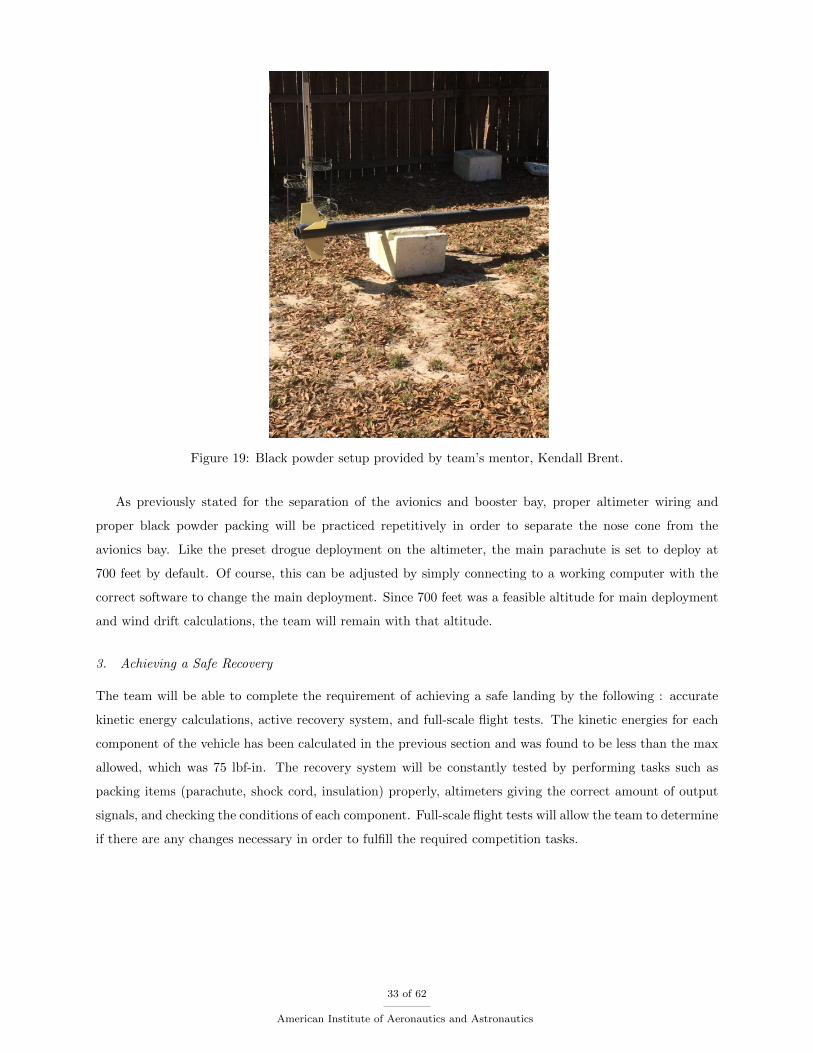
Figure 19: Black powder setup provided by team’s mentor, Kendall Brent.
As previously stated for the separation of the avionics and booster bay, proper altimeter wiring and
proper black powder packing will be practiced repetitively in order to separate the nose cone from the
avionics bay. Like the preset drogue deployment on the altimeter, the main parachute is set to deploy at
700 feet by default. Of course, this can be adjusted by simply connecting to a working computer with the
correct software to change the main deployment. Since 700 feet was a feasible altitude for main deployment
and wind drift calculations, the team will remain with that altitude.
3. Achieving a Safe Recovery
The team will be able to complete the requirement of achieving a safe landing by the following : accurate
kinetic energy calculations, active recovery system, and full-scale flight tests. The kinetic energies for each
component of the vehicle has been calculated in the previous section and was found to be less than the max
allowed, which was 75 lbf-in. The recovery system will be constantly tested by performing tasks such as
packing items (parachute, shock cord, insulation) properly, altimeters giving the correct amount of output
signals, and checking the conditions of each component. Full-scale flight tests will allow the team to determine
if there are any changes necessary in order to fulfill the required competition tasks.
33 of 62
American Institute of Aeronautics and Astronautics
4. Achieving Safe Recovery
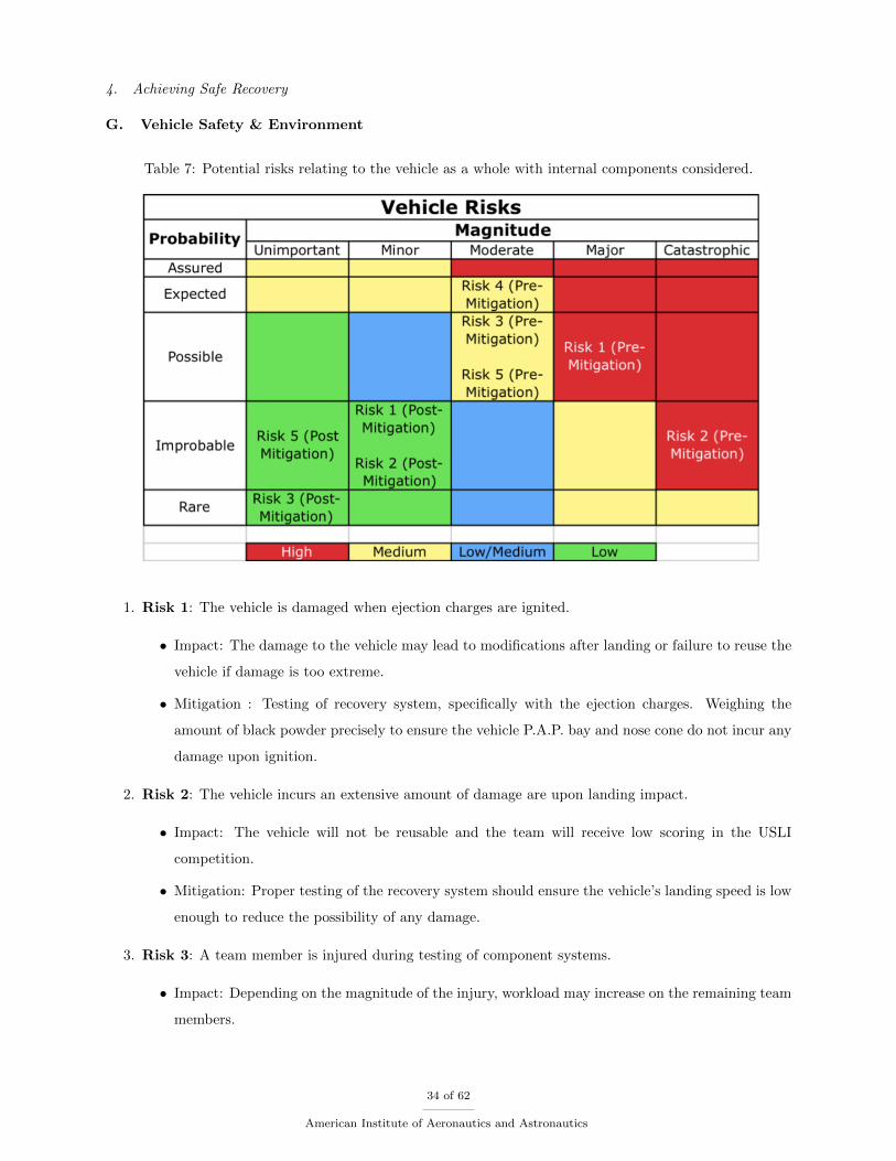
G. Vehicle Safety & Environment
Table 7: Potential risks relating to the vehicle as a whole with internal components considered.
1. Risk 1: The vehicle is damaged when ejection charges are ignited.
• Impact: The damage to the vehicle may lead to modifications after landing or failure to reuse the
vehicle if damage is too extreme.
• Mitigation : Testing of recovery system, specifically with the ejection charges. Weighing the
amount of black powder precisely to ensure the vehicle P.A.P. bay and nose cone do not incur any
damage upon ignition.
2. Risk 2: The vehicle incurs an extensive amount of damage are upon landing impact.
• Impact: The vehicle will not be reusable and the team will receive low scoring in the USLI
competition.
• Mitigation: Proper testing of the recovery system should ensure the vehicle’s landing speed is low
enough to reduce the possibility of any damage.
3. Risk 3: A team member is injured during testing of component systems.
• Impact: Depending on the magnitude of the injury, workload may increase on the remaining team
members.
34 of 62
American Institute of Aeronautics and Astronautics
• Mitigation: Pre-test briefing of all protocol must be performed so all team members are aware of
all possible risks involved and what to do to ensure safe testing.
4. Risk 4: Team members leave the state for school holidays.
• Impact: The team will be prohibited to meet to fulfill project milestones.
• Mitigation: The team has created an Overleaf file which will allow all team members to have
access to write and compile any scholarly documents related to the project.
5. Risk 5: The team may not receive enough funding to purchase all vehicle components.
• Impact: Without sufficient funding, the key components of the vehicle’s design, manufacturing,
and testing and possibly subsystems can be delayed when trying to reach benchmarks.
• Mitigation: The team will reach out to all available sources.
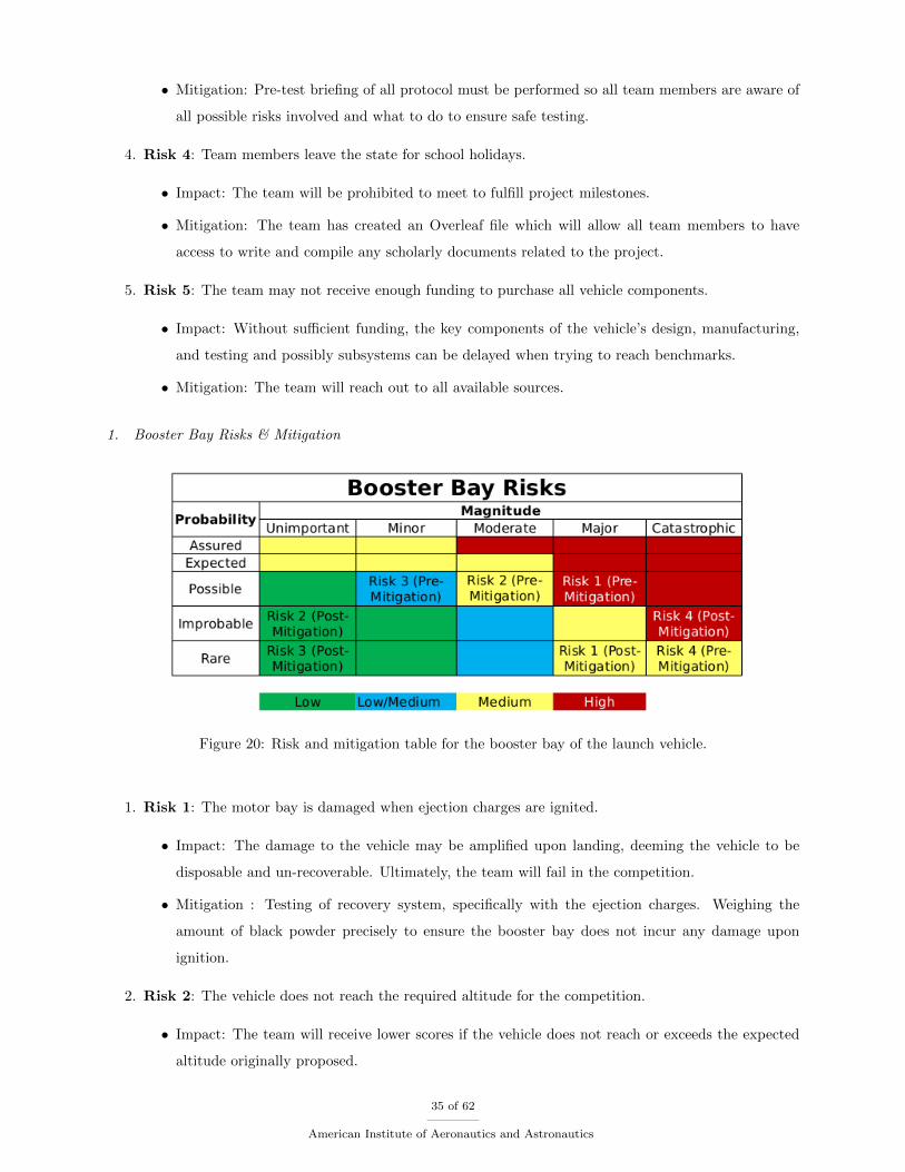
1. Booster Bay Risks & Mitigation
Figure 20: Risk and mitigation table for the booster bay of the launch vehicle.
1. Risk 1: The motor bay is damaged when ejection charges are ignited.
• Impact: The damage to the vehicle may be amplified upon landing, deeming the vehicle to be
disposable and un-recoverable. Ultimately, the team will fail in the competition.
• Mitigation : Testing of recovery system, specifically with the ejection charges. Weighing the
amount of black powder precisely to ensure the booster bay does not incur any damage upon
ignition.
2. Risk 2: The vehicle does not reach the required altitude for the competition.
• Impact: The team will receive lower scores if the vehicle does not reach or exceeds the expected
altitude originally proposed.
35 of 62
American Institute of Aeronautics and Astronautics
• Mitigation: Communication amongst the team members of any changes made regarding additional
mass and/or dimension changes.
3. Risk 3: Motor is compromised due to moisture.
• Impact: Motor fails to ignite, resulting in a failed launch. Tests can not be performed and data
cannot be collected.
• Mitigation: Properly store and transport motors. Avoid exposing the motor to wet environments
such as rain.
4. Risk 4: Motor fails and/or explodes.
• Impact: Launch is considered a failure. Part of all of the team’s rocket may be compromised.
Sensitive and costly electronics are disposed.
• Mitigation: Choosing to pack a motor with a kit rather than buy a prepacked motor. Have a
reliable vendor that will sell the highest quality motors in order to reduce the chance of motor
failure.
H. Payload Integration
Two unique scientific payloads will be integrated into our rocket: the PixyCam for hazard detection and a
Cooler Master CPU fan as a wind turbine for electricity generation. An Arduino Uno microcontroller will be
used to power the camera, as well as log data after deployment. Both payloads will be attached to a payload
tray specifically made for each through SolidWorks. These payload trays will be firmly nested within their
payload bays by one metal rod that is attached from end to end of the bulkheads. For extra support needed
to safely house the payload due to the stresses on the rocket body, a rigid G10 fiberglass coupler will serve
as the payload bay. The bulkheads for these payload bays will be of the same material as well. The one
metal rod will extend through each bulkhead and be secured by hardware. A metal eye-bolt will be attached
to the end nearest the nose cone, and will be used to attach the shock cord. The PixyCam payload bay
will be positioned below the drogue parachute, and located within the coupler. An ejection charge will be
targeted downwards in order to separate the avionics bay from the booster bay. The drogue parachute will
then deploy and force the PixyCam out of the rocket. When the payload bay is deployed, the shock cord
will be long and strong enough to place the camera well below the booster bay and other components on
descent.
Another payload consisting of a computer processing unit (CPU) fan is used as a wind turbine to harness
power on ascent. This payload will be housed permanently within a separate payload bay located in the
booster bay above the motor and will be stationary throughout flight. For added stability, the turbine bay
will be positioned between the center of gravity and center of pressure in order to minimize the moments
applied. The wind turbine bay will consist of the same material as the PixCam bay. The turbine bay will
be held in place within the bay by a specialized design created in Solidworks. The harnessing apparatus will
36 of 62
American Institute of Aeronautics and Astronautics
be 3D printed. Cellulose insulation will be stuffed between the turbine bay and the motor mount in order to
mitigate any potential damage that can be dealt to the bay. On the outside of the rocket at the position of
the turbine bay, two holes with an inch and a half in diameter will be placed above and below the turbine.
The hole above the turbine will use a straight 60 degree angle scoop to direct the airflow toward the turbine,
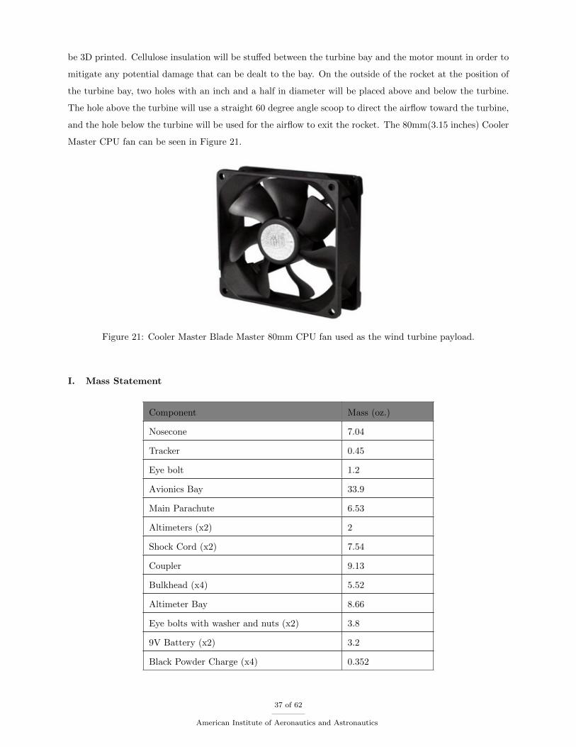
and the hole below the turbine will be used for the airflow to exit the rocket. The 80mm(3.15 inches) Cooler
Master CPU fan can be seen in Figure 21.
Figure 21: Cooler Master Blade Master 80mm CPU fan used as the wind turbine payload.
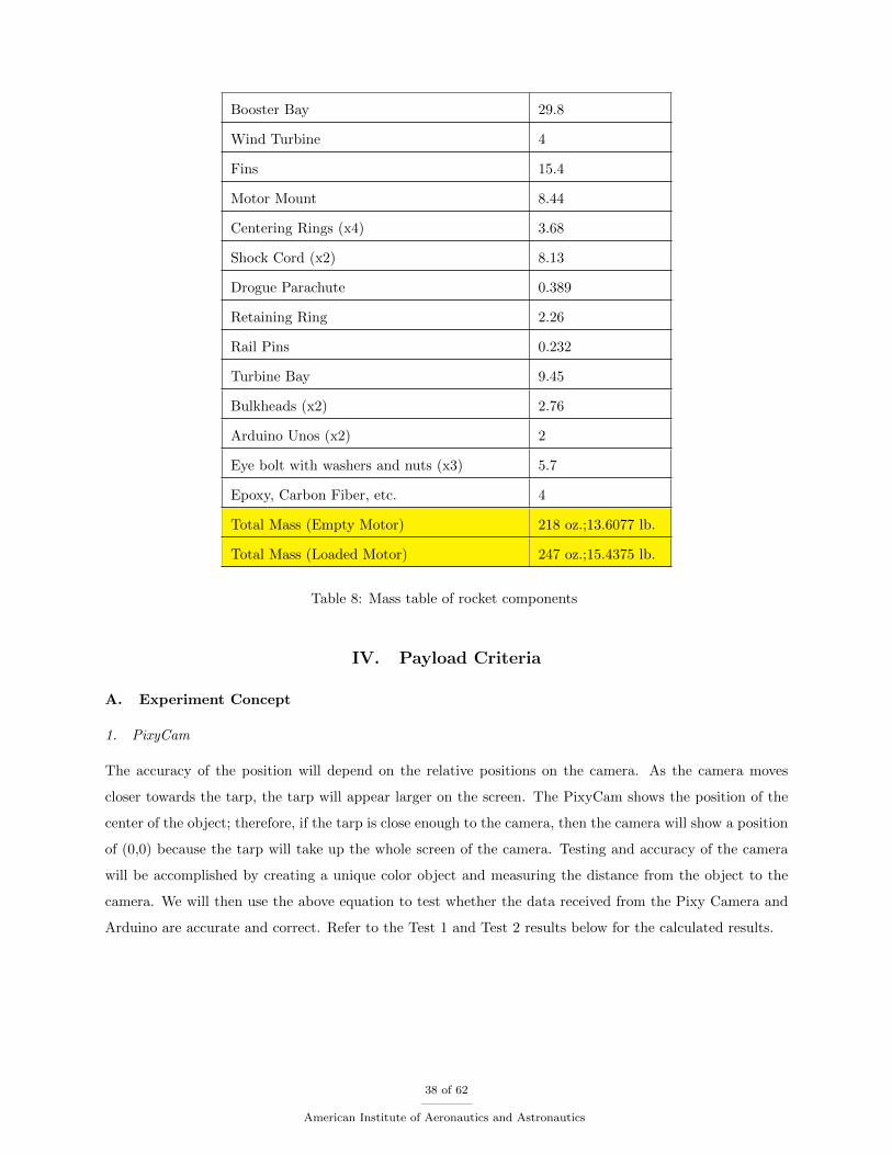
I. Mass Statement
Component Mass (oz.)
Nosecone 7.04
Tracker 0.45
Eye bolt 1.2
Avionics Bay 33.9
Main Parachute 6.53
Altimeters (x2) 2
Shock Cord (x2) 7.54
Coupler 9.13
Bulkhead (x4) 5.52
Altimeter Bay 8.66
Eye bolts with washer and nuts (x2) 3.8
9V Battery (x2) 3.2
Black Powder Charge (x4) 0.352
37 of 62
American Institute of Aeronautics and Astronautics
Booster Bay 29.8
Wind Turbine 4
Fins 15.4
Motor Mount 8.44
Centering Rings (x4) 3.68
Shock Cord (x2) 8.13
Drogue Parachute 0.389
Retaining Ring 2.26
Rail Pins 0.232
Turbine Bay 9.45
Bulkheads (x2) 2.76
Arduino Unos (x2) 2
Eye bolt with washers and nuts (x3) 5.7
Epoxy, Carbon Fiber, etc. 4
Total Mass (Empty Motor) 218 oz.;13.6077 lb.
Total Mass (Loaded Motor) 247 oz.;15.4375 lb.
Table 8: Mass table of rocket components
IV. Payload Criteria
A. Experiment Concept
1. PixyCam
The accuracy of the position will depend on the relative positions on the camera. As the camera moves
closer towards the tarp, the tarp will appear larger on the screen. The PixyCam shows the position of the
center of the object; therefore, if the tarp is close enough to the camera, then the camera will show a position
of (0,0) because the tarp will take up the whole screen of the camera. Testing and accuracy of the camera
will be accomplished by creating a unique color object and measuring the distance from the object to the
camera. We will then use the above equation to test whether the data received from the Pixy Camera and
Arduino are accurate and correct. Refer to the Test 1 and Test 2 results below for the calculated results.
38 of 62
American Institute of Aeronautics and Astronautics
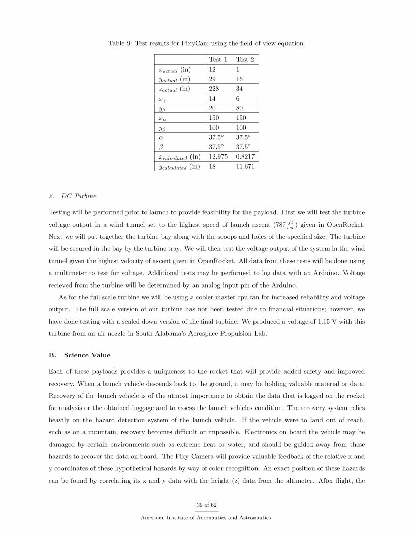
Table 9: Test results for PixyCam using the field-of-view equation.
Test 1 Test 2
xactual (in) 12 1
yactual (in) 29 16
zactual (in) 228 34
xγ 14 6
yβ 20 80
xα 150 150
yβ 100 100
α 37.5 37.5
β 37.5 37.5
xcalculated (in) 12.975 0.8217
ycalculated (in) 18 11.671
2. DC Turbine
Testing will be performed prior to launch to provide feasibility for the payload. First we will test the turbine
voltage output in a wind tunnel set to the highest speed of launch ascent (787 ftsec ) given in OpenRocket.
Next we will put together the turbine bay along with the scoops and holes of the specified size. The turbine
will be secured in the bay by the turbine tray. We will then test the voltage output of the system in the wind
tunnel given the highest velocity of ascent given in OpenRocket. All data from these tests will be done using
a multimeter to test for voltage. Additional tests may be performed to log data with an Arduino. Voltage
recieved from the turbine will be determined by an analog input pin of the Arduino.
As for the full scale turbine we will be using a cooler master cpu fan for increased reliability and voltage
output. The full scale version of our turbine has not been tested due to financial situations; however, we
have done testing with a scaled down version of the final turbine. We produced a voltage of 1.15 V with this
turbine from an air nozzle in South Alabama’s Aerospace Propulsion Lab.
B. Science Value
Each of these payloads provides a uniqueness to the rocket that will provide added safety and improved
recovery. When a launch vehicle descends back to the ground, it may be holding valuable material or data.
Recovery of the launch vehicle is of the utmost importance to obtain the data that is logged on the rocket
for analysis or the obtained luggage and to assess the launch vehicles condition. The recovery system relies
heavily on the hazard detection system of the launch vehicle. If the vehicle were to land out of reach,
such as on a mountain, recovery becomes difficult or impossible. Electronics on board the vehicle may be
damaged by certain environments such as extreme heat or water, and should be guided away from these
hazards to recover the data on board. The Pixy Camera will provide valuable feedback of the relative x and
y coordinates of these hypothetical hazards by way of color recognition. An exact position of these hazards
can be found by correlating its x and y data with the height (z) data from the altimeter. After flight, the
39 of 62
American Institute of Aeronautics and Astronautics
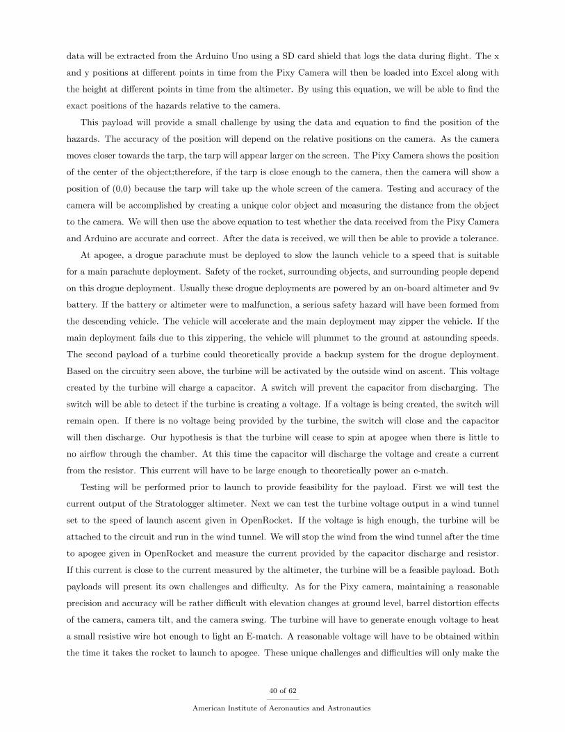
data will be extracted from the Arduino Uno using a SD card shield that logs the data during flight. The x
and y positions at different points in time from the Pixy Camera will then be loaded into Excel along with
the height at different points in time from the altimeter. By using this equation, we will be able to find the
exact positions of the hazards relative to the camera.
This payload will provide a small challenge by using the data and equation to find the position of the
hazards. The accuracy of the position will depend on the relative positions on the camera. As the camera
moves closer towards the tarp, the tarp will appear larger on the screen. The Pixy Camera shows the position
of the center of the object;therefore, if the tarp is close enough to the camera, then the camera will show a
position of (0,0) because the tarp will take up the whole screen of the camera. Testing and accuracy of the
camera will be accomplished by creating a unique color object and measuring the distance from the object
to the camera. We will then use the above equation to test whether the data received from the Pixy Camera
and Arduino are accurate and correct. After the data is received, we will then be able to provide a tolerance.
At apogee, a drogue parachute must be deployed to slow the launch vehicle to a speed that is suitable
for a main parachute deployment. Safety of the rocket, surrounding objects, and surrounding people depend
on this drogue deployment. Usually these drogue deployments are powered by an on-board altimeter and 9v
battery. If the battery or altimeter were to malfunction, a serious safety hazard will have been formed from
the descending vehicle. The vehicle will accelerate and the main deployment may zipper the vehicle. If the
main deployment fails due to this zippering, the vehicle will plummet to the ground at astounding speeds.
The second payload of a turbine could theoretically provide a backup system for the drogue deployment.
Based on the circuitry seen above, the turbine will be activated by the outside wind on ascent. This voltage
created by the turbine will charge a capacitor. A switch will prevent the capacitor from discharging. The
switch will be able to detect if the turbine is creating a voltage. If a voltage is being created, the switch will
remain open. If there is no voltage being provided by the turbine, the switch will close and the capacitor
will then discharge. Our hypothesis is that the turbine will cease to spin at apogee when there is little to
no airflow through the chamber. At this time the capacitor will discharge the voltage and create a current
from the resistor. This current will have to be large enough to theoretically power an e-match.
Testing will be performed prior to launch to provide feasibility for the payload. First we will test the
current output of the Stratologger altimeter. Next we can test the turbine voltage output in a wind tunnel
set to the speed of launch ascent given in OpenRocket. If the voltage is high enough, the turbine will be
attached to the circuit and run in the wind tunnel. We will stop the wind from the wind tunnel after the time
to apogee given in OpenRocket and measure the current provided by the capacitor discharge and resistor.
If this current is close to the current measured by the altimeter, the turbine will be a feasible payload. Both
payloads will present its own challenges and difficulty. As for the Pixy camera, maintaining a reasonable
precision and accuracy will be rather difficult with elevation changes at ground level, barrel distortion effects
of the camera, camera tilt, and the camera swing. The turbine will have to generate enough voltage to heat
a small resistive wire hot enough to light an E-match. A reasonable voltage will have to be obtained within
the time it takes the rocket to launch to apogee. These unique challenges and difficulties will only make the
40 of 62
American Institute of Aeronautics and Astronautics
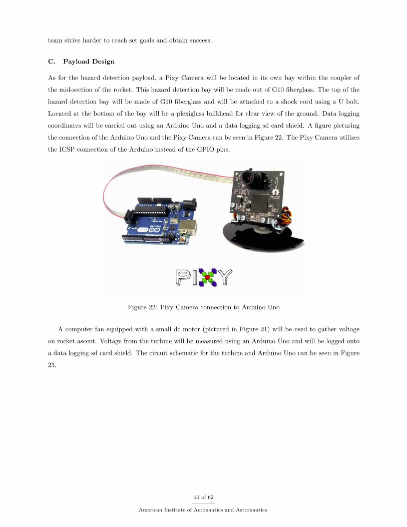
team strive harder to reach set goals and obtain success.
C. Payload Design
As for the hazard detection payload, a Pixy Camera will be located in its own bay within the coupler of
the mid-section of the rocket. This hazard detection bay will be made out of G10 fiberglass. The top of the
hazard detection bay will be made of G10 fiberglass and will be attached to a shock cord using a U bolt.
Located at the bottom of the bay will be a plexiglass bulkhead for clear view of the ground. Data logging
coordinates will be carried out using an Arduino Uno and a data logging sd card shield. A figure picturing
the connection of the Arduino Uno and the Pixy Camera can be seen in Figure 22. The Pixy Camera utilizes
the ICSP connection of the Arduino instead of the GPIO pins.
Figure 22: Pixy Camera connection to Arduino Uno
A computer fan equipped with a small dc motor (pictured in Figure 21) will be used to gather voltage
on rocket ascent. Voltage from the turbine will be measured using an Arduino Uno and will be logged onto
a data logging sd card shield. The circuit schematic for the turbine and Arduino Uno can be seen in Figure
23.
41 of 62
American Institute of Aeronautics and Astronautics
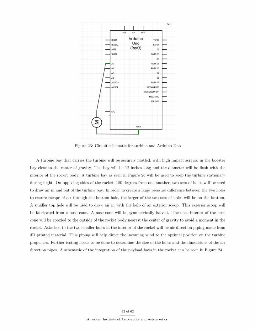
Figure 23: Circuit schematic for turbine and Arduino Uno
A turbine bay that carries the turbine will be securely nestled, with high impact screws, in the booster
bay close to the center of gravity. The bay will be 12 inches long and the diameter will be flush with the
interior of the rocket body. A turbine bay as seen in Figure 26 will be used to keep the turbine stationary
during flight. On opposing sides of the rocket, 180 degrees from one another, two sets of holes will be used
to draw air in and out of the turbine bay. In order to create a large pressure difference between the two holes
to ensure escape of air through the bottom hole, the larger of the two sets of holes will be on the bottom.
A smaller top hole will be used to draw air in with the help of an exterior scoop. This exterior scoop will
be fabricated from a nose cone. A nose cone will be symmetrically halved. The once interior of the nose
cone will be epoxied to the outside of the rocket body nearest the center of gravity to avoid a moment in the
rocket. Attached to the two smaller holes in the interior of the rocket will be air direction piping made from
3D printed material. This piping will help direct the incoming wind to the optimal position on the turbine
propellers. Further testing needs to be done to determine the size of the holes and the dimensions of the air
direction pipes. A schematic of the integration of the payload bays in the rocket can be seen in Figure 24.
42 of 62
American Institute of Aeronautics and Astronautics
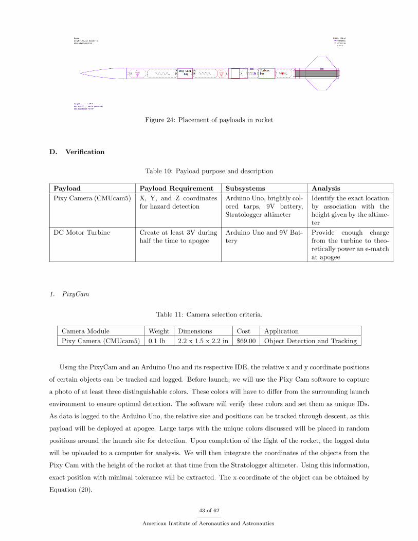
Figure 24: Placement of payloads in rocket
D. Verification
Table 10: Payload purpose and description
Payload Payload Requirement Subsystems Analysis
Pixy Camera (CMUcam5) X, Y, and Z coordinatesfor hazard detection
Arduino Uno, brightly col-ored tarps, 9V battery,Stratologger altimeter
Identify the exact locationby association with theheight given by the altime-ter
DC Motor Turbine Create at least 3V duringhalf the time to apogee
Arduino Uno and 9V Bat-tery
Provide enough chargefrom the turbine to theo-retically power an e-matchat apogee
1. PixyCam
Table 11: Camera selection criteria.
Camera Module Weight Dimensions Cost Application
Pixy Camera (CMUcam5) 0.1 lb 2.2 x 1.5 x 2.2 in $69.00 Object Detection and Tracking
Using the PixyCam and an Arduino Uno and its respective IDE, the relative x and y coordinate positions
of certain objects can be tracked and logged. Before launch, we will use the Pixy Cam software to capture
a photo of at least three distinguishable colors. These colors will have to differ from the surrounding launch
environment to ensure optimal detection. The software will verify these colors and set them as unique IDs.
As data is logged to the Arduino Uno, the relative size and positions can be tracked through descent, as this
payload will be deployed at apogee. Large tarps with the unique colors discussed will be placed in random
positions around the launch site for detection. Upon completion of the flight of the rocket, the logged data
will be uploaded to a computer for analysis. We will then integrate the coordinates of the objects from the
Pixy Cam with the height of the rocket at that time from the Stratologger altimeter. Using this information,
exact position with minimal tolerance will be extracted. The x-coordinate of the object can be obtained by
Equation (20).
43 of 62
American Institute of Aeronautics and Astronautics
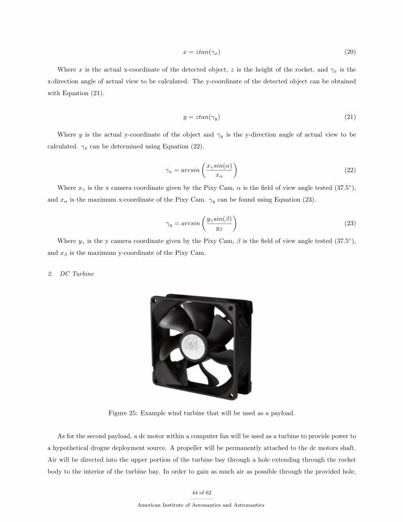
x = ztan(γx) (20)
Where x is the actual x-coordinate of the detected object, z is the height of the rocket, and γx is the
x-direction angle of actual view to be calculated. The y-coordinate of the detected object can be obtained
with Equation (21).
y = ztan(γy) (21)
Where y is the actual y-coordinate of the object and γy is the y-direction angle of actual view to be
calculated. γx can be determined using Equation (22).
γx = arcsin
(xγsin(α)
xα
)(22)
Where xγ is the x camera coordinate given by the Pixy Cam, α is the field of view angle tested (37.5),
and xα is the maximum x-coordinate of the Pixy Cam. γy can be found using Equation (23).
γy = arcsin
(yγsin(β)
yβ
)(23)
Where yγ is the y camera coordinate given by the Pixy Cam, β is the field of view angle tested (37.5),
and xβ is the maximum y-coordinate of the Pixy Cam.
2. DC Turbine
Figure 25: Example wind turbine that will be used as a payload.
As for the second payload, a dc motor within a computer fan will be used as a turbine to provide power to
a hypothetical drogue deployment source. A propeller will be permanently attached to the dc motors shaft.
Air will be directed into the upper portion of the turbine bay through a hole extending through the rocket
body to the interior of the turbine bay. In order to gain as much air as possible through the provided hole,
44 of 62
American Institute of Aeronautics and Astronautics
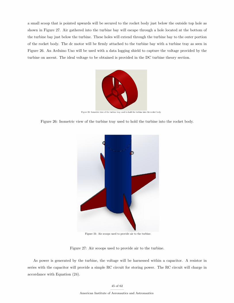
a small scoop that is pointed upwards will be secured to the rocket body just below the outside top hole as
shown in Figure 27. Air gathered into the turbine bay will escape through a hole located at the bottom of
the turbine bay just below the turbine. These holes will extend through the turbine bay to the outer portion
of the rocket body. The dc motor will be firmly attached to the turbine bay with a turbine tray as seen in
Figure 26. An Arduino Uno will be used with a data logging shield to capture the voltage provided by the
turbine on ascent. The ideal voltage to be obtained is provided in the DC turbine theory section.
Figure 26: Isometric view of the turbine tray used to hold the turbine into the rocket body.
Figure 27: Air scoops used to provide air to the turbine.
As power is generated by the turbine, the voltage will be harnessed within a capacitor. A resistor in
series with the capacitor will provide a simple RC circuit for storing power. The RC circuit will charge in
accordance with Equation (24).
45 of 62
American Institute of Aeronautics and Astronautics
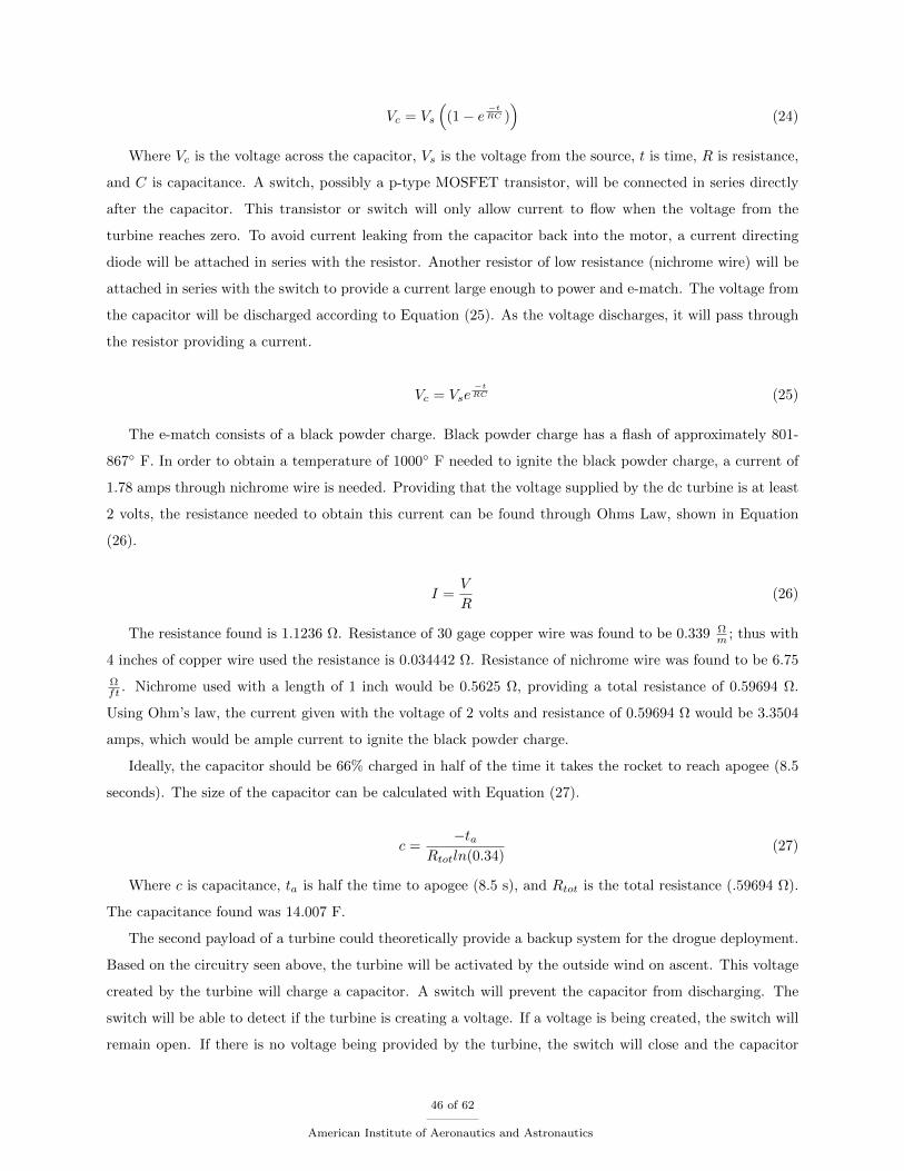
Vc = Vs
((1− e
−tRC )
)(24)
Where Vc is the voltage across the capacitor, Vs is the voltage from the source, t is time, R is resistance,
and C is capacitance. A switch, possibly a p-type MOSFET transistor, will be connected in series directly
after the capacitor. This transistor or switch will only allow current to flow when the voltage from the
turbine reaches zero. To avoid current leaking from the capacitor back into the motor, a current directing
diode will be attached in series with the resistor. Another resistor of low resistance (nichrome wire) will be
attached in series with the switch to provide a current large enough to power and e-match. The voltage from
the capacitor will be discharged according to Equation (25). As the voltage discharges, it will pass through
the resistor providing a current.
Vc = Vse−tRC (25)
The e-match consists of a black powder charge. Black powder charge has a flash of approximately 801-
867 F. In order to obtain a temperature of 1000 F needed to ignite the black powder charge, a current of
1.78 amps through nichrome wire is needed. Providing that the voltage supplied by the dc turbine is at least
2 volts, the resistance needed to obtain this current can be found through Ohms Law, shown in Equation
(26).
I =V
R(26)
The resistance found is 1.1236 Ω. Resistance of 30 gage copper wire was found to be 0.339 Ωm ; thus with
4 inches of copper wire used the resistance is 0.034442 Ω. Resistance of nichrome wire was found to be 6.75
Ωft . Nichrome used with a length of 1 inch would be 0.5625 Ω, providing a total resistance of 0.59694 Ω.
Using Ohm’s law, the current given with the voltage of 2 volts and resistance of 0.59694 Ω would be 3.3504
amps, which would be ample current to ignite the black powder charge.
Ideally, the capacitor should be 66% charged in half of the time it takes the rocket to reach apogee (8.5
seconds). The size of the capacitor can be calculated with Equation (27).
c =−ta
Rtotln(0.34)(27)
Where c is capacitance, ta is half the time to apogee (8.5 s), and Rtot is the total resistance (.59694 Ω).
The capacitance found was 14.007 F.
The second payload of a turbine could theoretically provide a backup system for the drogue deployment.
Based on the circuitry seen above, the turbine will be activated by the outside wind on ascent. This voltage
created by the turbine will charge a capacitor. A switch will prevent the capacitor from discharging. The
switch will be able to detect if the turbine is creating a voltage. If a voltage is being created, the switch will
remain open. If there is no voltage being provided by the turbine, the switch will close and the capacitor
46 of 62
American Institute of Aeronautics and Astronautics
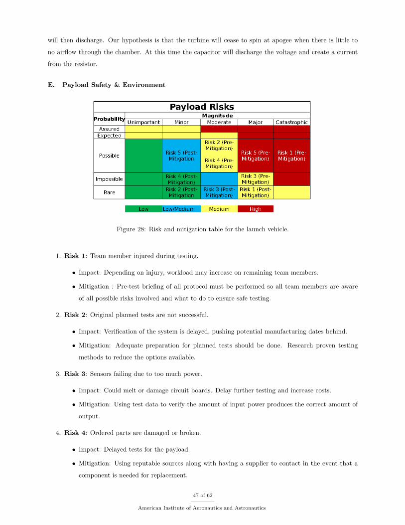
will then discharge. Our hypothesis is that the turbine will cease to spin at apogee when there is little to
no airflow through the chamber. At this time the capacitor will discharge the voltage and create a current
from the resistor.
E. Payload Safety & Environment
Figure 28: Risk and mitigation table for the launch vehicle.
1. Risk 1: Team member injured during testing.
• Impact: Depending on injury, workload may increase on remaining team members.
• Mitigation : Pre-test briefing of all protocol must be performed so all team members are aware
of all possible risks involved and what to do to ensure safe testing.
2. Risk 2: Original planned tests are not successful.
• Impact: Verification of the system is delayed, pushing potential manufacturing dates behind.
• Mitigation: Adequate preparation for planned tests should be done. Research proven testing
methods to reduce the options available.
3. Risk 3: Sensors failing due to too much power.
• Impact: Could melt or damage circuit boards. Delay further testing and increase costs.
• Mitigation: Using test data to verify the amount of input power produces the correct amount of
output.
4. Risk 4: Ordered parts are damaged or broken.
• Impact: Delayed tests for the payload.
• Mitigation: Using reputable sources along with having a supplier to contact in the event that a
component is needed for replacement.
47 of 62
American Institute of Aeronautics and Astronautics
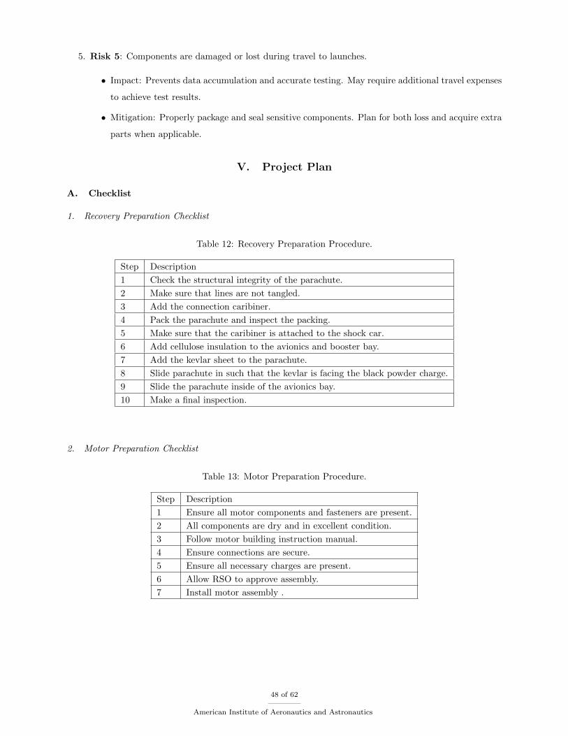
5. Risk 5: Components are damaged or lost during travel to launches.
• Impact: Prevents data accumulation and accurate testing. May require additional travel expenses
to achieve test results.
• Mitigation: Properly package and seal sensitive components. Plan for both loss and acquire extra
parts when applicable.
V. Project Plan
A. Checklist
1. Recovery Preparation Checklist
Table 12: Recovery Preparation Procedure.
Step Description
1 Check the structural integrity of the parachute.
2 Make sure that lines are not tangled.
3 Add the connection caribiner.
4 Pack the parachute and inspect the packing.
5 Make sure that the caribiner is attached to the shock car.
6 Add cellulose insulation to the avionics and booster bay.
7 Add the kevlar sheet to the parachute.
8 Slide parachute in such that the kevlar is facing the black powder charge.
9 Slide the parachute inside of the avionics bay.
10 Make a final inspection.
2. Motor Preparation Checklist
Table 13: Motor Preparation Procedure.
Step Description
1 Ensure all motor components and fasteners are present.
2 All components are dry and in excellent condition.
3 Follow motor building instruction manual.
4 Ensure connections are secure.
5 Ensure all necessary charges are present.
6 Allow RSO to approve assembly.
7 Install motor assembly .
48 of 62
American Institute of Aeronautics and Astronautics
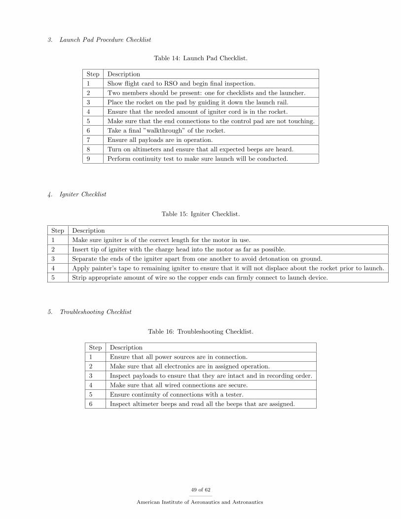
3. Launch Pad Procedure Checklist
Table 14: Launch Pad Checklist.
Step Description
1 Show flight card to RSO and begin final inspection.
2 Two members should be present: one for checklists and the launcher.
3 Place the rocket on the pad by guiding it down the launch rail.
4 Ensure that the needed amount of igniter cord is in the rocket.
5 Make sure that the end connections to the control pad are not touching.
6 Take a final ”walkthrough” of the rocket.
7 Ensure all payloads are in operation.
8 Turn on altimeters and ensure that all expected beeps are heard.
9 Perform continuity test to make sure launch will be conducted.
4. Igniter Checklist
Table 15: Igniter Checklist.
Step Description
1 Make sure igniter is of the correct length for the motor in use.
2 Insert tip of igniter with the charge head into the motor as far as possible.
3 Separate the ends of the igniter apart from one another to avoid detonation on ground.
4 Apply painter’s tape to remaining igniter to ensure that it will not displace about the rocket prior to launch.
5 Strip appropriate amount of wire so the copper ends can firmly connect to launch device.
5. Troubleshooting Checklist
Table 16: Troubleshooting Checklist.
Step Description
1 Ensure that all power sources are in connection.
2 Make sure that all electronics are in assigned operation.
3 Inspect payloads to ensure that they are intact and in recording order.
4 Make sure that all wired connections are secure.
5 Ensure continuity of connections with a tester.
6 Inspect altimeter beeps and read all the beeps that are assigned.
49 of 62
American Institute of Aeronautics and Astronautics

6. Post Launch Checklist
Table 17: Post Launch Checklist.
Step Description
1 If the rocket is out of view, use tracker to locate the rocket.
2 Make sure all rocket pieces are separated.
3 Check that the charges have ignited.
4 Allow the materials officer to check the rocket’s integrity.
5 If possible, reassemble and return to the launch site.
6 Allow RSO to check altimeter’s recorded altitude.
B. Safety and Quality Assurance
1. Risk Mitigation
We have taken extensive mitigation measures in order to assure that the risks involved with our launch
procedures are contained at a manageable level. In previously outlined risk matrices, risks have been demon-
strated to be mitigated to an acceptable level. After mitigation, almost all of the risks have been classified as
either ”medium/low” or ”low” and the few risks that have been identified as ”medium risk” after mitigation
are considered either improbably or rare.
2. Environmental Concerns
Our team has also set in place standards and precautions in order to minimize the impact our rocket, and
the project as a whole, will have on the environment. The first of these environmental concerns is the black
powder. The black powder used for the parachute ejection in our rocket could have affect the environment
if it is not handled properly and if it were to be spilled. The black powder, along with the ignitors for the
motor and the e-matches used to ignite the black powder will be stored in a safe, dry place in accordance
with the recommended storage of black powder. After the e-matches have been burned and recovered from
our rocket, they will be disposed of properly. The next potential impact to the environment is the rocket
motor. Measures, including a launch pad and rail made of metal, will help to mitigate the risk of fire
when the motor is ignited. After the launch is completed, the motor will also be disposed of safely. Other
components that may pose a unique risk to the environment can simply be mitigated by proper disposal or
recycling. These components include batteries, excess fiberglass, electronic components, paint, and epoxy.
With proper handling and disposal of these components, they should pose no risk of negatively impacting
the environment. In addition to the risks the our project poses to the environment, there are also some
risks to our project, and to our team, from the environment. Adverse weather conditions, such as rain or
excessive cold, may delay testing or launching procedures, however, this risk has been mitigated by allowing
for multiple test sites and times. All electronic and explosive components of the rocket will be properly
sealed and stored to avoid any affect of moisture, which could cause corrosion or deformation. Heat and
50 of 62
American Institute of Aeronautics and Astronautics
sun exposure are also a risk that must be accounted for as they can lead to dehydration, heat stroke, or sun
burn. In order to mitigate the risk of heat, the team will take breaks when needed, properly protect from
the sun, and stay well hydrated while at launches and other testing procedures.
3. Safety Officer
For this year’s competition, the safety officer for the University of South Alabama Launch Society will be
Nghia Huynh. Mr. Huynh will be responsible for the safety of those around him and his job is to ensure that
both the team and the mission are preserved at all times. As of to date, he holds a Tripoli level 2 certification.
With that being said, Mr. Huynh will have to follow a number of required precautions so that no member
or spectator is injured or harmed due to any failures during the planning, testing, construction, or flights of
the rocket. Mr. Huynh will consistently keep the team informed of any hazards and safety concerns, issues,
and documentations throughout the project. He will create his own personal checklist which will guide the
rest of the team to perform the correct pre-flight and post-flight procedures. Risk matrices will provide the
team a way to analyze many of the hazards and failure possibilities as well as addressing any environmental
issues that may be encountered.
Since the safety officer is certified through Tripoli, he will be required to keep all the rocket motors,
explosives, and igniters at all times in a secure, red-painted, plywood-reinforced steel box. The steel box will
be kept off campus due to it being illegal to keep on campus. The only time the box should be unlocked is
when a motor is being removed to be used. Other than to either use or store motors, the box is to remain
closed and secured as all times to avoid any potential explosive hazards.
The University of South Alabama Launch society will obey all rules, regulations, and laws set forth by
the University of South Alabama, City of Mobile, State of Alabama, Federal Government, and any other
regions that will be encountered during travel. Along with the preceding laws, all traffic and airspace laws
must be obeyed at all times as well. This includes, but not limited to, low-explosives laws and rocketry
associations such as NAR and Tripoli. According to NFPA 1127 code for high power rocketry, a level 2
or 3 flier whose responsibility and duty during the operation of high power rockets is to confirm a rocket’s
compliance with the applicable provisions of this code, be confident that the rocket will fly in a safe manner,
designate the areas of the launch site, and oversee the safety of all spectators and participants. Along with
Tripoli regulations, NAR regulations will be obeyed as well. One example for a NAR regulation is the only
use lightweight, non-metal parts for the nose, body, and fins for the rocket . Ultimately, the Range Safety
Officer will decide if the rocket is prepared for flight. His decisions and instructions will be respectfully
followed. Along with these regulations and laws, all FAA waiver requirements will be met according to the
time table scheduled.
The highest priority for the University of South Alabama’s Launch Society is the safety of everyone in the
surroundings. The key for this is to be aware of the processes taking place and alert at all times in the event
of hazardous events. Proper personal protective equipment will be worn at all times during the construction
phase of the project. When dealing with any type of chemicals, a fume hood will be used to prevent any
51 of 62
American Institute of Aeronautics and Astronautics
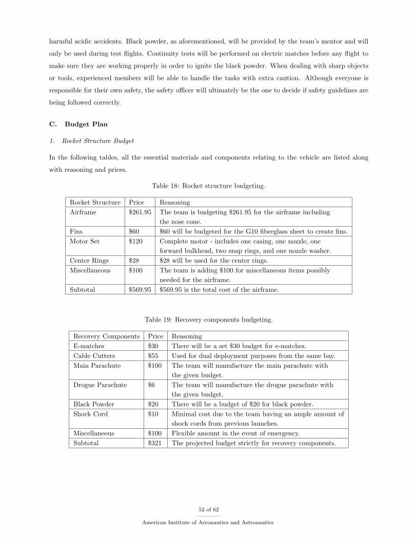
harmful acidic accidents. Black powder, as aforementioned, will be provided by the team’s mentor and will
only be used during test flights. Continuity tests will be performed on electric matches before any flight to
make sure they are working properly in order to ignite the black powder. When dealing with sharp objects
or tools, experienced members will be able to handle the tasks with extra caution. Although everyone is
responsible for their own safety, the safety officer will ultimately be the one to decide if safety guidelines are
being followed correctly.
C. Budget Plan
1. Rocket Structure Budget
In the following tables, all the essential materials and components relating to the vehicle are listed along
with reasoning and prices.
Table 18: Rocket structure budgeting.
Rocket Structure Price Reasoning
Airframe $261.95 The team is budgeting $261.95 for the airframe including
the nose cone.
Fins $60 $60 will be budgeted for the G10 fiberglass sheet to create fins.
Motor Set $120 Complete motor - includes one casing, one nozzle, one
forward bulkhead, two snap rings, and one nozzle washer.
Center Rings $28 $28 will be used for the center rings.
Miscellaneous $100 The team is adding $100 for miscellaneous items possibly
needed for the airframe.
Subtotal $569.95 $569.95 is the total cost of the airframe.
Table 19: Recovery components budgeting.
Recovery Components Price Reasoning
E-matches $30 There will be a set $30 budget for e-matches.
Cable Cutters $55 Used for dual deployment purposes from the same bay.
Main Parachute $100 The team will manufacture the main parachute with
the given budget.
Drogue Parachute $6 The team will manufacture the drogue parachute with
the given budget.
Black Powder $20 There will be a budget of $20 for black powder.
Shock Cord $10 Minimal cost due to the team having an ample amount of
shock cords from previous launches.
Miscellaneous $100 Flexible amount in the event of emergency.
Subtotal $321 The projected budget strictly for recovery components.
52 of 62
American Institute of Aeronautics and Astronautics
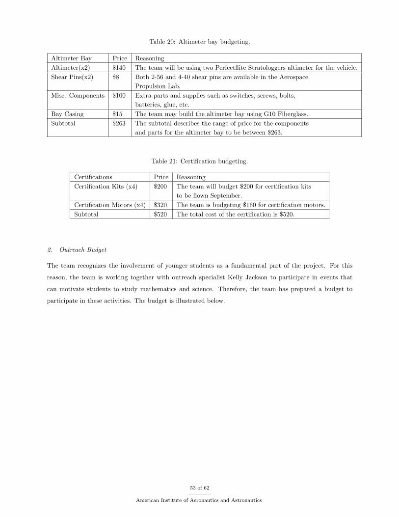
Table 20: Altimeter bay budgeting.
Altimeter Bay Price Reasoning
Altimeter(x2) $140 The team will be using two Perfectflite Stratologgers altimeter for the vehicle.
Shear Pins(x2) $8 Both 2-56 and 4-40 shear pins are available in the Aerospace
Propulsion Lab.
Misc. Components $100 Extra parts and supplies such as switches, screws, bolts,
batteries, glue, etc.
Bay Casing $15 The team may build the altimeter bay using G10 Fiberglass.
Subtotal $263 The subtotal describes the range of price for the components
and parts for the altimeter bay to be between $263.
Table 21: Certification budgeting.
Certifications Price Reasoning
Certification Kits (x4) $200 The team will budget $200 for certification kits
to be flown September.
Certification Motors (x4) $320 The team is budgeting $160 for certification motors.
Subtotal $520 The total cost of the certification is $520.
2. Outreach Budget
The team recognizes the involvement of younger students as a fundamental part of the project. For this
reason, the team is working together with outreach specialist Kelly Jackson to participate in events that
can motivate students to study mathematics and science. Therefore, the team has prepared a budget to
participate in these activities. The budget is illustrated below.
53 of 62
American Institute of Aeronautics and Astronautics
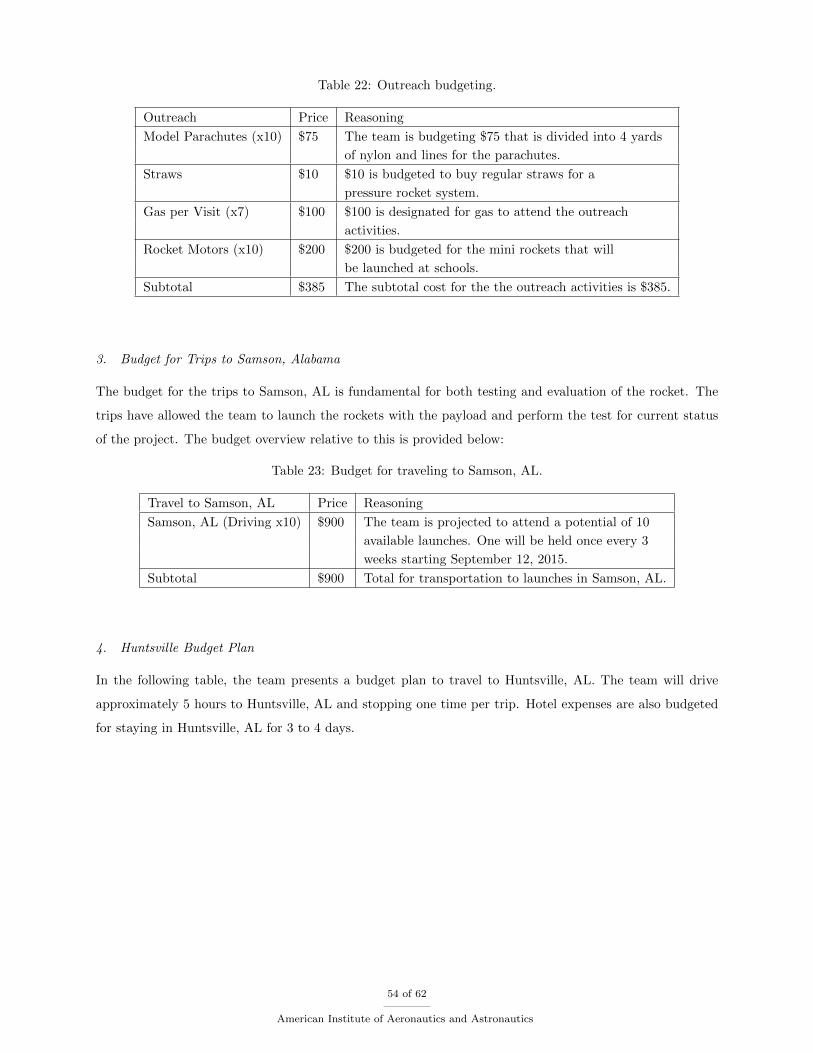
Table 22: Outreach budgeting.
Outreach Price Reasoning
Model Parachutes (x10) $75 The team is budgeting $75 that is divided into 4 yards
of nylon and lines for the parachutes.
Straws $10 $10 is budgeted to buy regular straws for a
pressure rocket system.
Gas per Visit (x7) $100 $100 is designated for gas to attend the outreach
activities.
Rocket Motors (x10) $200 $200 is budgeted for the mini rockets that will
be launched at schools.
Subtotal $385 The subtotal cost for the the outreach activities is $385.
3. Budget for Trips to Samson, Alabama
The budget for the trips to Samson, AL is fundamental for both testing and evaluation of the rocket. The
trips have allowed the team to launch the rockets with the payload and perform the test for current status
of the project. The budget overview relative to this is provided below:
Table 23: Budget for traveling to Samson, AL.
Travel to Samson, AL Price Reasoning
Samson, AL (Driving x10) $900 The team is projected to attend a potential of 10
available launches. One will be held once every 3
weeks starting September 12, 2015.
Subtotal $900 Total for transportation to launches in Samson, AL.
4. Huntsville Budget Plan
In the following table, the team presents a budget plan to travel to Huntsville, AL. The team will drive
approximately 5 hours to Huntsville, AL and stopping one time per trip. Hotel expenses are also budgeted
for staying in Huntsville, AL for 3 to 4 days.
54 of 62
American Institute of Aeronautics and Astronautics
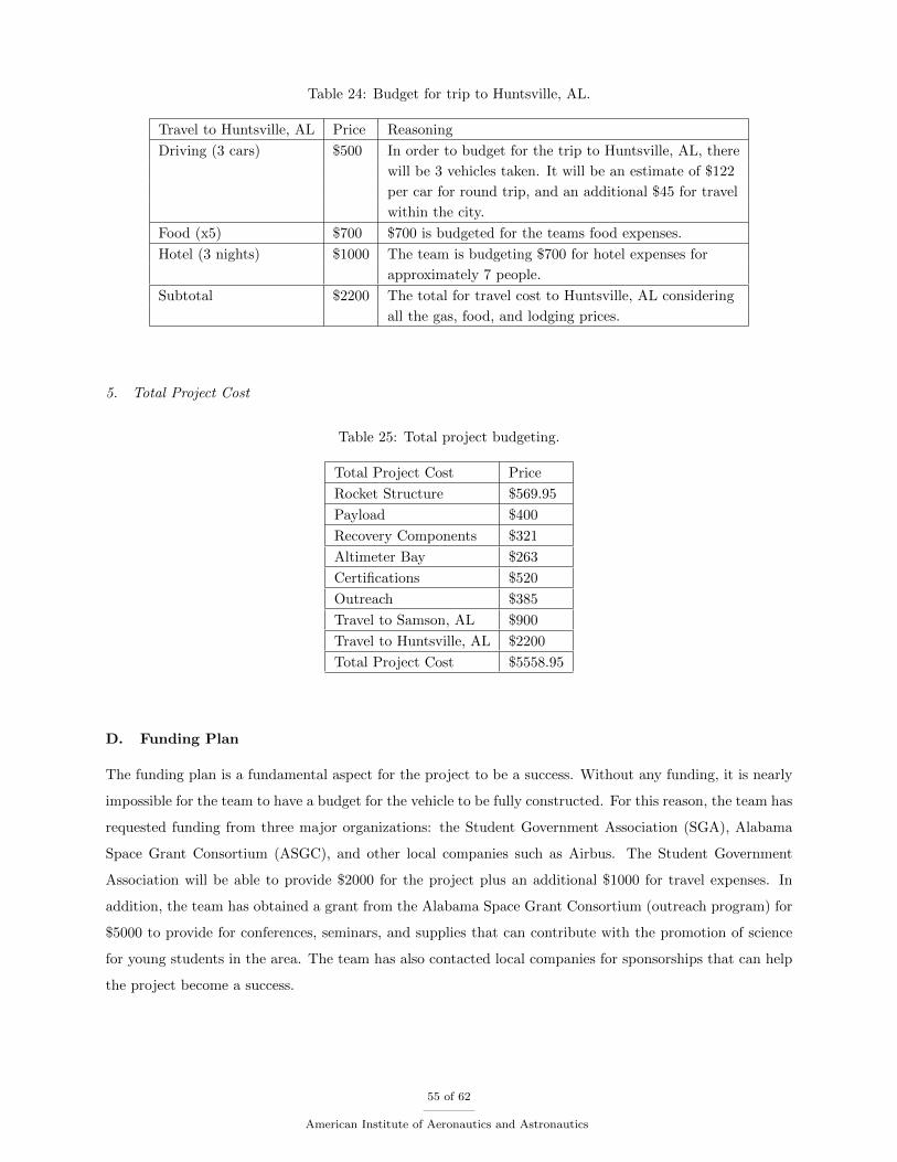
Table 24: Budget for trip to Huntsville, AL.
Travel to Huntsville, AL Price Reasoning
Driving (3 cars) $500 In order to budget for the trip to Huntsville, AL, there
will be 3 vehicles taken. It will be an estimate of $122
per car for round trip, and an additional $45 for travel
within the city.
Food (x5) $700 $700 is budgeted for the teams food expenses.
Hotel (3 nights) $1000 The team is budgeting $700 for hotel expenses for
approximately 7 people.
Subtotal $2200 The total for travel cost to Huntsville, AL considering
all the gas, food, and lodging prices.
5. Total Project Cost
Table 25: Total project budgeting.
Total Project Cost Price
Rocket Structure $569.95
Payload $400
Recovery Components $321
Altimeter Bay $263
Certifications $520
Outreach $385
Travel to Samson, AL $900
Travel to Huntsville, AL $2200
Total Project Cost $5558.95
D. Funding Plan
The funding plan is a fundamental aspect for the project to be a success. Without any funding, it is nearly
impossible for the team to have a budget for the vehicle to be fully constructed. For this reason, the team has
requested funding from three major organizations: the Student Government Association (SGA), Alabama
Space Grant Consortium (ASGC), and other local companies such as Airbus. The Student Government
Association will be able to provide $2000 for the project plus an additional $1000 for travel expenses. In
addition, the team has obtained a grant from the Alabama Space Grant Consortium (outreach program) for
$5000 to provide for conferences, seminars, and supplies that can contribute with the promotion of science
for young students in the area. The team has also contacted local companies for sponsorships that can help
the project become a success.
55 of 62
American Institute of Aeronautics and Astronautics
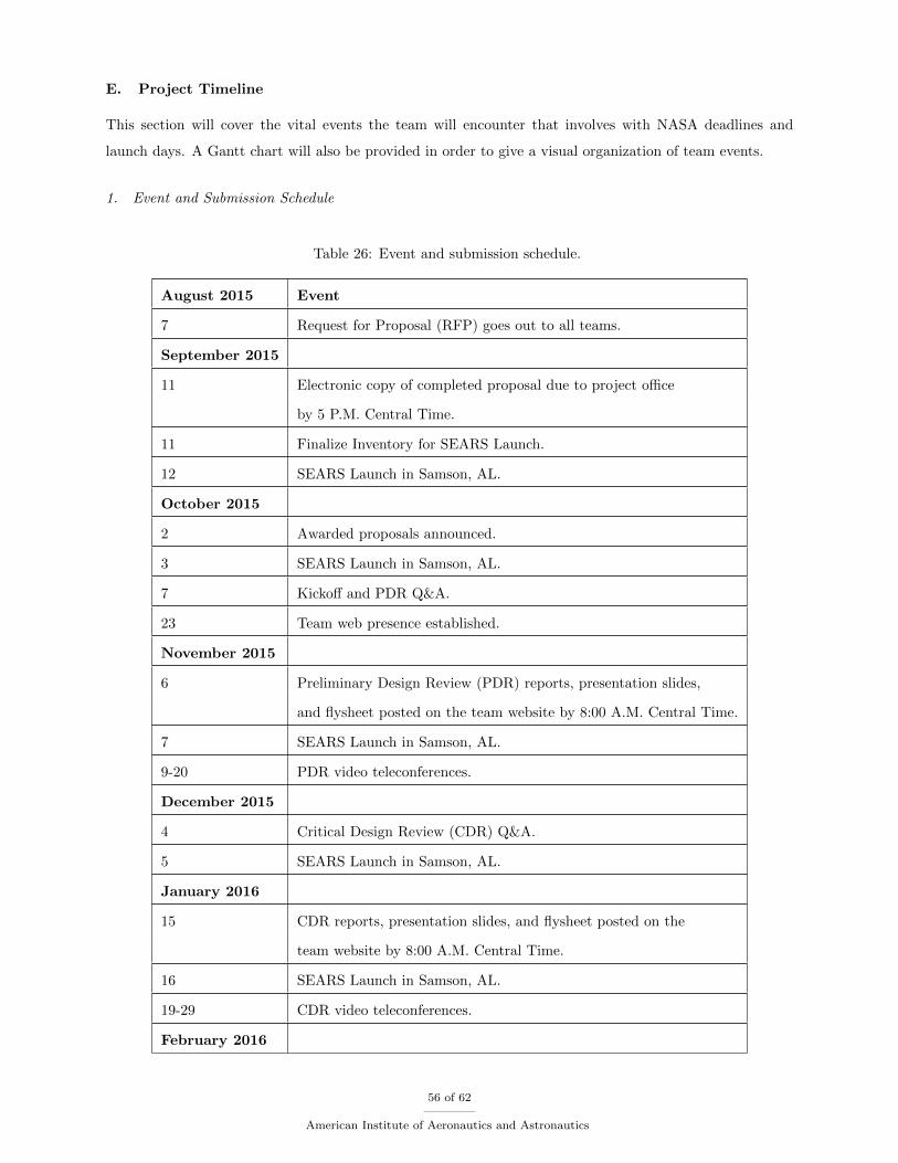
E. Project Timeline
This section will cover the vital events the team will encounter that involves with NASA deadlines and
launch days. A Gantt chart will also be provided in order to give a visual organization of team events.
1. Event and Submission Schedule
Table 26: Event and submission schedule.
August 2015 Event
7 Request for Proposal (RFP) goes out to all teams.
September 2015
11 Electronic copy of completed proposal due to project office
by 5 P.M. Central Time.
11 Finalize Inventory for SEARS Launch.
12 SEARS Launch in Samson, AL.
October 2015
2 Awarded proposals announced.
3 SEARS Launch in Samson, AL.
7 Kickoff and PDR Q&A.
23 Team web presence established.
November 2015
6 Preliminary Design Review (PDR) reports, presentation slides,
and flysheet posted on the team website by 8:00 A.M. Central Time.
7 SEARS Launch in Samson, AL.
9-20 PDR video teleconferences.
December 2015
4 Critical Design Review (CDR) Q&A.
5 SEARS Launch in Samson, AL.
January 2016
15 CDR reports, presentation slides, and flysheet posted on the
team website by 8:00 A.M. Central Time.
16 SEARS Launch in Samson, AL.
19-29 CDR video teleconferences.
February 2016
56 of 62
American Institute of Aeronautics and Astronautics
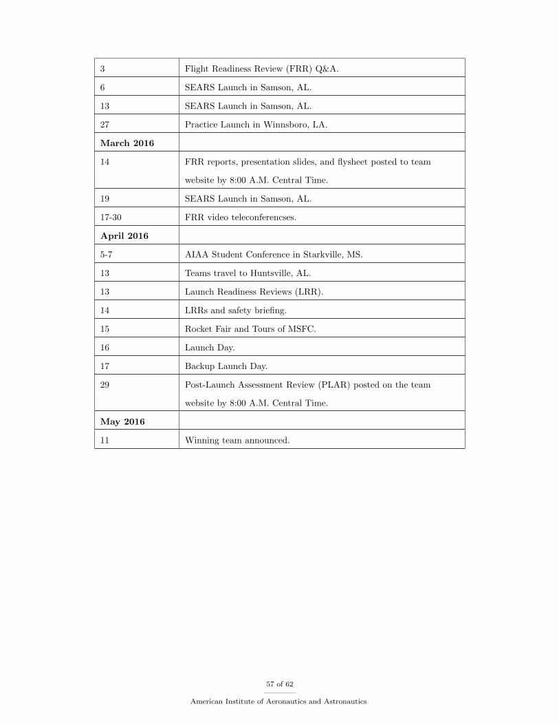
3 Flight Readiness Review (FRR) Q&A.
6 SEARS Launch in Samson, AL.
13 SEARS Launch in Samson, AL.
27 Practice Launch in Winnsboro, LA.
March 2016
14 FRR reports, presentation slides, and flysheet posted to team
website by 8:00 A.M. Central Time.
19 SEARS Launch in Samson, AL.
17-30 FRR video teleconferencses.
April 2016
5-7 AIAA Student Conference in Starkville, MS.
13 Teams travel to Huntsville, AL.
13 Launch Readiness Reviews (LRR).
14 LRRs and safety briefing.
15 Rocket Fair and Tours of MSFC.
16 Launch Day.
17 Backup Launch Day.
29 Post-Launch Assessment Review (PLAR) posted on the team
website by 8:00 A.M. Central Time.
May 2016
11 Winning team announced.
57 of 62
American Institute of Aeronautics and Astronautics
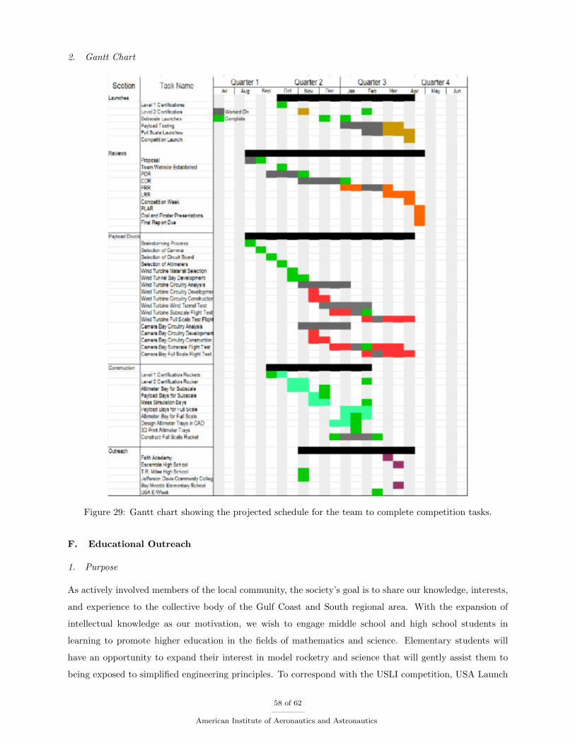
2. Gantt Chart
Figure 29: Gantt chart showing the projected schedule for the team to complete competition tasks.
F. Educational Outreach
1. Purpose
As actively involved members of the local community, the society’s goal is to share our knowledge, interests,
and experience to the collective body of the Gulf Coast and South regional area. With the expansion of
intellectual knowledge as our motivation, we wish to engage middle school and high school students in
learning to promote higher education in the fields of mathematics and science. Elementary students will
have an opportunity to expand their interest in model rocketry and science that will gently assist them to
being exposed to simplified engineering principles. To correspond with the USLI competition, USA Launch
58 of 62
American Institute of Aeronautics and Astronautics
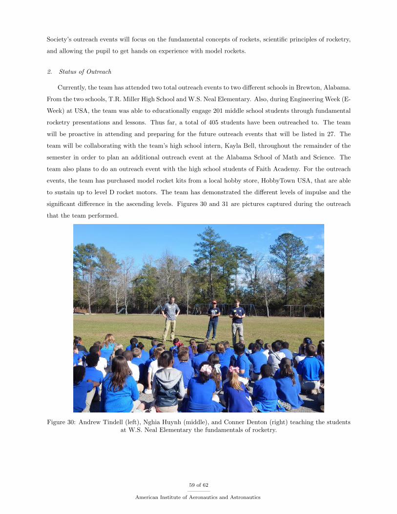
Society’s outreach events will focus on the fundamental concepts of rockets, scientific principles of rocketry,
and allowing the pupil to get hands on experience with model rockets.
2. Status of Outreach
Currently, the team has attended two total outreach events to two different schools in Brewton, Alabama.
From the two schools, T.R. Miller High School and W.S. Neal Elementary. Also, during Engineering Week (E-
Week) at USA, the team was able to educationally engage 201 middle school students through fundamental
rocketry presentations and lessons. Thus far, a total of 405 students have been outreached to. The team
will be proactive in attending and preparing for the future outreach events that will be listed in 27. The
team will be collaborating with the team’s high school intern, Kayla Bell, throughout the remainder of the
semester in order to plan an additional outreach event at the Alabama School of Math and Science. The
team also plans to do an outreach event with the high school students of Faith Academy. For the outreach
events, the team has purchased model rocket kits from a local hobby store, HobbyTown USA, that are able
to sustain up to level D rocket motors. The team has demonstrated the different levels of impulse and the
significant difference in the ascending levels. Figures 30 and 31 are pictures captured during the outreach
that the team performed.
Figure 30: Andrew Tindell (left), Nghia Huynh (middle), and Conner Denton (right) teaching the studentsat W.S. Neal Elementary the fundamentals of rocketry.
59 of 62
American Institute of Aeronautics and Astronautics
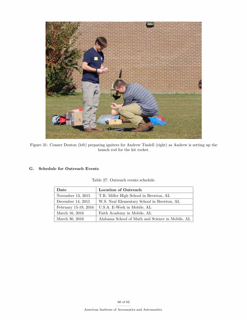
Figure 31: Conner Denton (left) preparing igniters for Andrew Tindell (right) as Andrew is setting up thelaunch rod for the kit rocket.
G. Schedule for Outreach Events
Table 27: Outreach events schedule.
Date Location of Outreach
November 13, 2015 T.R. Miller High School in Brewton, AL
December 14, 2015 W.S. Neal Elementary School in Brewton, AL
February 15-19, 2016 U.S.A. E-Week in Mobile, AL
March 16, 2016 Faith Academy in Mobile, AL
March 30, 2016 Alabama School of Math and Science in Mobile, AL
60 of 62
American Institute of Aeronautics and Astronautics
VI. Conclusion
It is apparent through this document that the USA Launch Society has made every effort possible to
prepare a detailed plan for the remainder of the competition. The payloads chosen for design include hazard
detection and wind turbine. The hazard detection payload will use a PixyCam to survey possible landing
hazards upon descent, and the wind turbine payload will determine the feasibility of generating a large enough
voltage to theoretically deploy the drogue parachute, as discussed in this document. The team has already
overcome numerous issues regarding the payload development including safety issues with alternative energy
supplies for deployments, a comparatively low budget and group size, timing issues for the wind turbine
power supply, etc. The team plans to continue the hard effort towards the payload design and construction.
Also, the team is ecstatic about the exciting opportunities in the near future.
The proposed payloads offer increased safety and cleaner energy sources for the future of rocketry. In
rocky, rough climates such as Mars, hazard detection is a key to the future. With increased interest in future
missions to the Red Planet, innovations in hazard detection for descent vehicles is essential. This can save
NASA money and effectiveness. Due to questionable climate change conditions as well as financial concerns,
alternative energies are crucial. Alternative energies are the future of this world due to increasing restrictions
and fossil fuel depletion. Harnessing wind is an energy that will never cease to exist.
Acknowledgments
Before this report is complete, the USA Launch Society would like to thank the following people for their
support and expertise:
• Dr. Carlos Montalvo
• Dr. David Nelson
• Dr. John Steadman
• Dr. Dhanajay Tambe
• Dr. Richard Kramer
• Mr. John Hansel
• Mr. Kendall Brent
• Mr. Chris Short
All of these men have vastly helped to improve the efforts of the USA Launch Society. Their future
support is monumental to the longevity of this team and project.
61 of 62
American Institute of Aeronautics and Astronautics
References
1National Aeronautics and Space Administration. Nasa student launch non-academic handbook. pages 58–59, 2015.
2C. W. Besserer. Principle of Guided Missile Design. D. Van Nostrand Company, Inc., 2004.
3Wade W. Huebsch Alric P. Rothmayer Bruce R. Munson, Theodore H. Okiishi. Fundamentals of Fluid Mechanics. John
Wiley and Sons, Inc., 7th edition, 2013.
4Mark Canepa. Modern High-Power Rocketry. Trafford Publishing, 2nd edition, 2004.
5Gerald M. Gregorek. Aerodynamic Drag of Model Rockets. Estes Industries, Inc., tr-11 model rocket technical report
edition, 1970.
6HARA. How to size ejection charges. pages 1–2, 2016.
7MatWeb. G-10 fiberglass epoxy laminate sheet. http://www.matweb.com/search/datasheet.aspx?matguid=8337b2d050d44da1b8a9a5e61b0d5f85&ckck=1.
Accessed: 1/13/2015.
8Richard Nakka. Parachute descent calculations. http://www.rocketmime.com/rockets/descent.html. Accessed:
1/11/2016.
9Sampo Niskanen. Development of an Open Source Model Rocket Simulation Software. Helsinki University of Technology,
Finland, 2009.
10George M. Siouris. Missile Guidance and Control Systems. Springer, 2004.
11Ashish Tewari. Atmospheric and Space Flight Dynamics. Birkhauser, 2007.
12Stephen Timoshenko and James Monroe. Theory of Elastic Stability. New York McGraw-Hill, 1961.
62 of 62
American Institute of Aeronautics and Astronautics