Embed Size (px)
DESCRIPTION
Flight Performance of Lightweight Gyroplanes
Citation preview
28TH INTERNATIONAL CONGRESS OF THE AERONAUTICAL SCIENCES
1
Abstract
The flight performance of modern lightweight gyroplanes is investigated in this paper. The final goal is to explore the possibilities increasing the airspeed of gyroplanes.
The gyroplane flight physics are examined briefly particularly the autorotation during vertical descent and forward flight. The early research work, such as the gliding tests with a PCA-2 gyroplane conducted by Wheatley in the thirties are considered as basis for the analysis of modern gyroplanes.
The validated simulation model of a new generation gyroplane of type MTOsport is used in order to investigate relevant flight performance parameters. The glide ratios of the rotor alone and of the total aircraft are determined and the results are discussed in comparison with the PCA-2 data.
Finally the potential of gyroplane performance improvement by means of drag reduction is discussed by comparison with a light airplane.
Nomenclature
rD Rotor plane angle of attack
rblD Rotor blade local angle of attack with respect to rotor plane
U Air density H Rotor blade incidence angle V Rotor solidity
rbl\ Rotor blade azimuth angle
rZ Rotor rotational speed
DvertC Rotor parachutal drag coefficient during vertical descent
DparC Aircraft parasitic drag coefficient
DC Rotor blade profile drag coefficient
LC Rotor blade profile lift coefficient D Total aircraft drag
parD Aircraft parasitic drag
rD Rotor drag (without hub and fittings)
propF Propeller force
stabF Horizontal stabilizer force G Weight force
rI Rotor rotational moment of inertia L Total aircraft lift force
rL Rotor lift force
blr Distance of rotor blade local forces to the shaft
rr Rotor radius
rS Rotor disc area
blt Rotor blade chord
ru Horizontal inflow velocity of the rotor plane
V Airspeed rblV Rotor blade local velocity DWw Rotor downwash velocity rw Vertical inflow velocity of the rotor
plane effrw , Effective vertical airflow through the
rotor plane rX Rotor horizontal force (positive in
forward direction)
FLIGHT PERFORMANCE OF LIGHTWEIGHT GYROPLANES
Holger Duda, Insa Pruter German Aerospace Center Institute of Flight Systems
Lilienthalplatz 7 D-38108 Braunschweig
[email protected]; [email protected]
Keywords: flight performance, gyroplane, gyrocopter, autogyro
Duda, Pruter
2
rblX Rotor blade local horizontal force (positive in forward direction)
rZ Rotor vertical force (positive in upward direction)
rblZ Rotor blade local vertical force (positive in upward direction)
1 Introduction
A gyroplane is an aircraft that gets lift from a freely turning rotary wing and which derives its thrust from an engine-driven propeller [1]. Historically, this type of aircraft has been known as autogiro or gyrocopter. It was developed by Juan de la Cierva and in 1923; it was the first rotary wing aircraft flying. Early gyroplanes were powered by engines in a tractor (pulling) configuration, like the Cierva C.30 from 1932 which was produced 180 times by 1945.
Gyroplanes became largely neglected after significant improvements in helicopters. In the fifties there was some revival of interest in the gyroplane by Igor Bensen’s home-built gyroplane kits with an open airframe and the Fairey Company in Britain. During early sixties, single- and two-seater gyroplanes were developed for the private aviation market; one of it gaining a starring role in a 1967 James Bond film – the little Nellie, a Ken Wallis WA-116.
Today in Europe several manufacturers sell single- and two-seater gyroplanes for the private aviation market, such as Spanish ELA Aviation, Italian Magni Gyro, German ROTORTEC GmbH or AutoGyro GmbH; the latter produced and sold more than thousand gyroplanes since 2004. This boom can be explained by the fascinating flying characteristics in combination with the robustness and cost efficiency of this kind of flight vehicle.
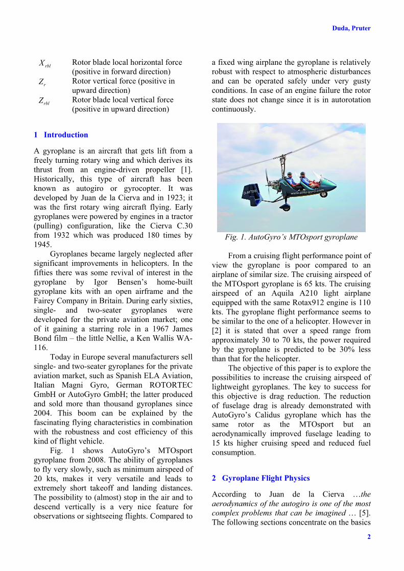
Fig. 1 shows AutoGyro’s MTOsport gyroplane from 2008. The ability of gyroplanes to fly very slowly, such as minimum airspeed of 20 kts, makes it very versatile and leads to extremely short takeoff and landing distances. The possibility to (almost) stop in the air and to descend vertically is a very nice feature for observations or sightseeing flights. Compared to
a fixed wing airplane the gyroplane is relatively robust with respect to atmospheric disturbances and can be operated safely under very gusty conditions. In case of an engine failure the rotor state does not change since it is in autorotation continuously.
Fig. 1. AutoGyro’s MTOsport gyroplane From a cruising flight performance point of
view the gyroplane is poor compared to an airplane of similar size. The cruising airspeed of the MTOsport gyroplane is 65 kts. The cruising airspeed of an Aquila A210 light airplane equipped with the same Rotax912 engine is 110 kts. The gyroplane flight performance seems to be similar to the one of a helicopter. However in [2] it is stated that over a speed range from approximately 30 to 70 kts, the power required by the gyroplane is predicted to be 30% less than that for the helicopter.
The objective of this paper is to explore the possibilities to increase the cruising airspeed of lightweight gyroplanes. The key to success for this objective is drag reduction. The reduction of fuselage drag is already demonstrated with AutoGyro’s Calidus gyroplane which has the same rotor as the MTOsport but an aerodynamically improved fuselage leading to 15 kts higher cruising speed and reduced fuel consumption.
2 Gyroplane Flight Physics
According to Juan de la Cierva …the aerodynamics of the autogiro is one of the most complex problems that can be imagined … [5]. The following sections concentrate on the basics
3
FLIGHT PERFORMANCE OF LIGHTWEIGHT GYROPLANES
of autorotation during vertical descent and forward flight.
2.1 Vertical Autorotation
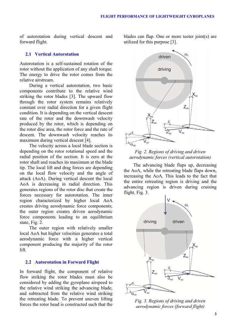
Autorotation is a self-sustained rotation of the rotor without the application of any shaft torque. The energy to drive the rotor comes from the relative airstream.
During a vertical autorotation, two basic components contribute to the relative wind striking the rotor blades [3]. The upward flow through the rotor system remains relatively constant over radial direction for a given flight condition. It is depending on the vertical descent rate of the rotor and the downwash velocity produced by the rotor, which is depending on the rotor disc area, the rotor force and the rate of descent. The downwash velocity reaches its maximum during vertical descent [4].
The velocity across a local blade section is depending on the rotor rotational speed and the radial position of the section. It is zero at the rotor shaft and reaches its maximum at the blade tip. The local lift and drag forces are depending on the local flow velocity and the angle of attack (AoA). During vertical descent the local AoA is decreasing in radial direction. This generates regions of the rotor disc that create the forces necessary for autorotation. The inner region characterized by higher local AoA creates driving aerodynamic force components; the outer region creates driven aerodynamic force components leading to an equilibrium state, Fig. 2.
The outer region with relatively smaller local AoA but higher velocities generates a total aerodynamic force with a higher vertical component producing the majority of the rotor lift.
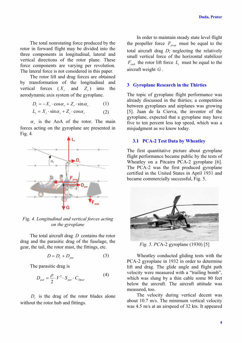
2.2 Autorotation in Forward Flight
In forward flight, the component of relative flow striking the rotor blades must also be considered by adding the gyroplane airspeed to the relative wind striking the advancing blade, and subtracted from the relative wind striking the retreating blade. To prevent uneven lifting forces the rotor head is constructed such that the
blades can flap. One or more teeter joint(s) are utilized for this purpose [3].
Fig. 2. Regions of driving and driven
aerodynamic forces (vertical autorotation) The advancing blade flaps up, decreasing
the AoA, while the retreating blade flaps down, increasing the AoA. This leads to the fact that the entire retreating region is driving and the advancing region is driven during cruising flight, Fig. 3.
Fig. 3. Regions of driving and driven aerodynamic forces (forward flight)
Duda, Pruter
4
The total nonrotating force produced by the
rotor in forward flight may be divided into the three components in longitudinal, lateral and vertical directions of the rotor plane. These force components are varying per revolution. The lateral force is not considered in this paper.
The rotor lift and drag forces are obtained by transformation of the longitudinal and vertical forces ( rX and rZ ) into the aerodynamic axis system of the gyroplane.
rrrrr
rrrrr
ZXLZXD
DDDD
cossinsincos
��� ���� (1)
(2)
rD is the AoA of the rotor. The main forces acting on the gyroplane are presented in Fig. 4.
Fig. 4. Longitudinal and vertical forces acting on the gyroplane
The total aircraft drag D contains the rotor
drag and the parasitic drag of the fuselage, the gear, the tail, the rotor mast, the fittings, etc.
parr DDD � (3)
The parasitic drag is
Dparparpar CSVD ��� 2
2U
(4)
rD is the drag of the rotor blades alone
without the rotor hub and fittings.
In order to maintain steady state level flight the propeller force propF must be equal to the total aircraft drag D; neglecting the relatively small vertical force of the horizontal stabilizer
stabF the rotor lift force rL must be equal to the aircraft weight G .
3 Gyroplane Research in the Thirties
The topic of gyroplane flight performance was already discussed in the thirties; a competition between gyroplanes and airplanes was growing [5]. Juan de la Cierva, the inventor of the gyroplane, expected that a gyroplane may have five to ten percent less top speed, which was a misjudgment as we know today.
3.1 PCA-2 Test Data by Wheatley
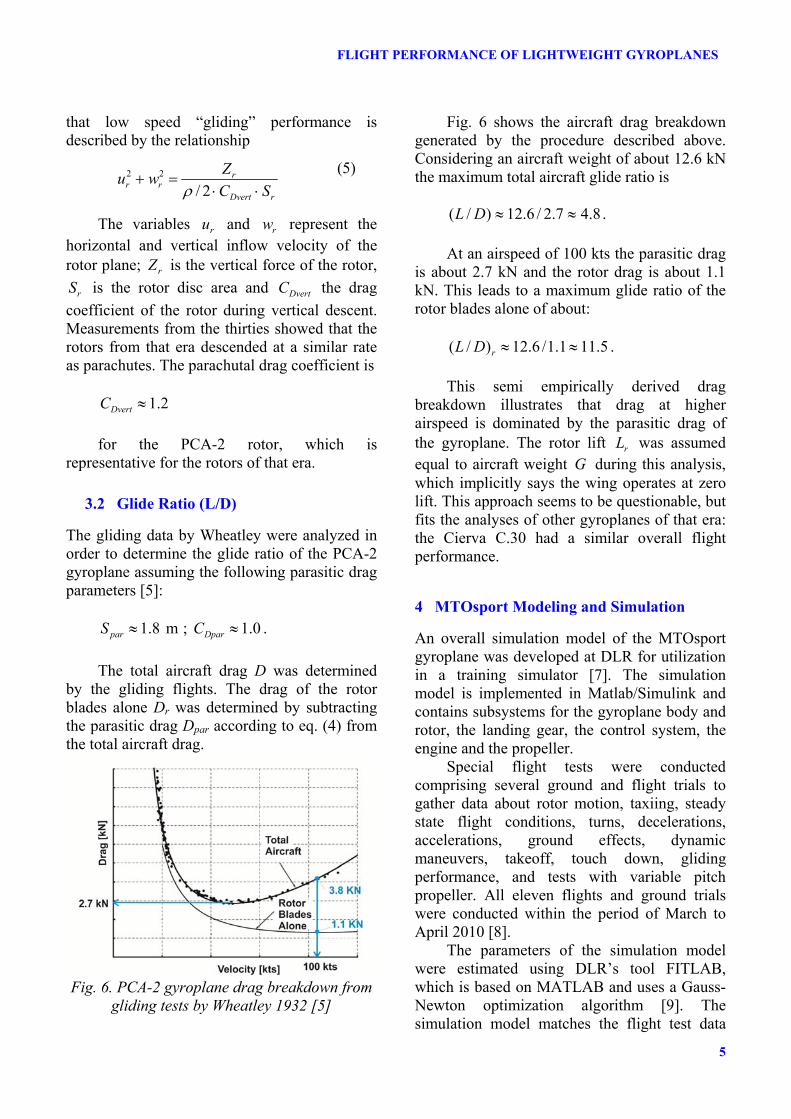
The first quantitative picture about gyroplane flight performance became public by the tests of Wheatley on a Pitcairn PCA-2 gyroplane [6]. The PCA-2 was the first produced gyroplane certified in the United States in April 1931 and became commercially successful, Fig. 5.
Fig. 5. PCA-2 gyroplane (1930) [5]
Wheatley conducted gliding tests with the
PCA-2 gyroplane in 1932 in order to determine lift and drag. The glide angle and flight path velocity were measured with a “trailing bomb”, which was slung by a thin cable some 80 feet below the aircraft. The aircraft attitude was measured, too.
The velocity during vertical decent was about 10.7 m/s. The minimum vertical velocity was 4.5 m/s at an airspeed of 32 kts. It appeared
5
FLIGHT PERFORMANCE OF LIGHTWEIGHT GYROPLANES
that low speed “gliding” performance is described by the relationship
rDvert
rrr SC
Zwu��
�2/
22
U (5)
The variables ru and rw represent the horizontal and vertical inflow velocity of the rotor plane; rZ is the vertical force of the rotor,
rS is the rotor disc area and DvertC the drag coefficient of the rotor during vertical descent. Measurements from the thirties showed that the rotors from that era descended at a similar rate as parachutes. The parachutal drag coefficient is
2.1|DvertC
for the PCA-2 rotor, which is
representative for the rotors of that era.
3.2 Glide Ratio (L/D)
The gliding data by Wheatley were analyzed in order to determine the glide ratio of the PCA-2 gyroplane assuming the following parasitic drag parameters [5]:
8.1|parS m ; 0.1|DparC . The total aircraft drag D was determined
by the gliding flights. The drag of the rotor blades alone Dr was determined by subtracting the parasitic drag Dpar according to eq. (4) from the total aircraft drag.
Fig. 6. PCA-2 gyroplane drag breakdown from
gliding tests by Wheatley 1932 [5]
Fig. 6 shows the aircraft drag breakdown generated by the procedure described above. Considering an aircraft weight of about 12.6 kN the maximum total aircraft glide ratio is
8.47.2/6.12)/( ||DL .
At an airspeed of 100 kts the parasitic drag
is about 2.7 kN and the rotor drag is about 1.1 kN. This leads to a maximum glide ratio of the rotor blades alone of about:
5.111.1/6.12)/( ||rDL .
This semi empirically derived drag
breakdown illustrates that drag at higher airspeed is dominated by the parasitic drag of the gyroplane. The rotor lift rL was assumed equal to aircraft weight G during this analysis, which implicitly says the wing operates at zero lift. This approach seems to be questionable, but fits the analyses of other gyroplanes of that era: the Cierva C.30 had a similar overall flight performance.
4 MTOsport Modeling and Simulation
An overall simulation model of the MTOsport gyroplane was developed at DLR for utilization in a training simulator [7]. The simulation model is implemented in Matlab/Simulink and contains subsystems for the gyroplane body and rotor, the landing gear, the control system, the engine and the propeller.
Special flight tests were conducted comprising several ground and flight trials to gather data about rotor motion, taxiing, steady state flight conditions, turns, decelerations, accelerations, ground effects, dynamic maneuvers, takeoff, touch down, gliding performance, and tests with variable pitch propeller. All eleven flights and ground trials were conducted within the period of March to April 2010 [8].
The parameters of the simulation model were estimated using DLR’s tool FITLAB, which is based on MATLAB and uses a Gauss-Newton optimization algorithm [9]. The simulation model matches the flight test data
Duda, Pruter
6
adequately for several maneuvers like steady state flights in the entire airspeed range, dynamic maneuvers in the roll, pitch and yaw axes as well as acceleration and deceleration flights [8].
4.1 Rotor
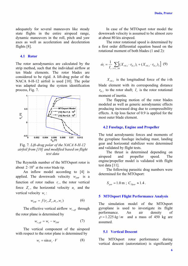
The rotor aerodynamics are calculated by the strip method, such that the individual airflow at ten blade elements. The rotor blades are considered to be rigid. A lift-drag polar of the NACA 8-H-12 airfoil is used [10]. The polar was adapted during the system identification process, Fig. 7.
0 0.002 0.004 0.006 0.008 0.01 0.012-0.5
0
0.5
1
CD [1]
CL [1
]
MTOsport Model[10] Re=1,8 � 106
[10] Re=2,6 � 106
Fig. 7. Lift-drag polar of the NACA 8-H-12
airfoil from [10] and modified based on flight test data
The Reynolds number of the MTOsport rotor is about 6102 � at the rotor blade tip.
An inflow model according to [4] is applied. The downwash velocity DWw is a function of rotor radius rr , the rotor vertical force rZ , the horizontal velocity ru and the vertical velocity rw :
),,,( rrrrDW wuZrfw (6)
The effective vertical airflow effrw , through the rotor plane is determined by
DWreffr www � , (7)
The vertical component of the airspeed with respect to the rotor plane is determined by
Vw rr � Dsin (8)
In case of the MTOsport rotor model the downwash velocity is assumed to be almost zero at about 80 kts airspeed.
The rotor rotational speed is determined by a first order differential equation based on the rotational moment of both blades (1 and 2):
> @¦
��� 10...1
2,,1,, )()(1i
iblirbliblirblr
r rXrXI
Z�
(9)
irblX , is the longitudinal force of the i-th blade element with its corresponding distance
iblr , to the rotor shaft; rI is the rotor rotational moment of inertia.
The flapping motion of the rotor blades modeled as well as generic aerodynamic effects producing increased drag due to compressibility effects. A tip loss factor of 0.9 is applied for the most outer blade element.
4.2 Fuselage, Engine and Propeller
The total aerodynamic forces and moments of the gyroplane fuselage including mast, landing gear and horizontal stabilizer were determined and validated by flight tests.
The thrust is determined depending on airspeed and propeller speed. The engine/propeller model is validated with flight test data [11].
The following parasitic drag numbers were determined for the MTOsport:
0.1 parS m ; 4.1|DparC .
5 MTOsport Flight Performance Analysis
The simulation model of the MTOsport gyroplane is used to investigate its flight performance. An air density of
/225.1 mkg U and a mass of 450 kg are assumed.
5.1 Vertical Descent
The MTOsport rotor performance during vertical descent (autorotation) is significantly
7
FLIGHT PERFORMANCE OF LIGHTWEIGHT GYROPLANES
better than of the PCA-2 rotor. According to eq. (5) the parachutal drag coefficient is
0.2|DvertC .
This means that the MTOsport rotor scaled
to the size of the PCA-2 rotor would have almost 70% higher vertical force at the same vertical descent rate. This may be explained by the different blade airfoils and the different solidity V , which is the quotient of blade area by rotor disk area.
r
bl
rt�
S
V (10)
The rotor solidity is three times higher for PCA-2 rotor. Furthermore, the rotor blades of the MTOsport are made of aluminum with a very smooth surface while the PCA-2 blades were a covered wooden rip construction.
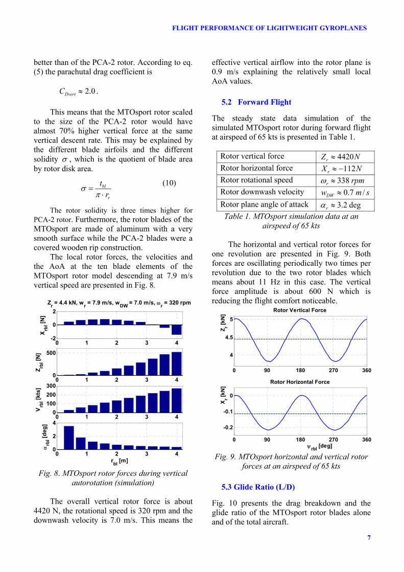
The local rotor forces, the velocities and the AoA at the ten blade elements of the MTOsport rotor model descending at 7.9 m/s vertical speed are presented in Fig. 8.
0 1 2 3 4-2
0
2
X rbl [N
]
Zr = 4.4 kN, wr = 7.9 m/s, wDW = 7.0 m/s, Zr = 320 rpm
0 1 2 3 40
500
Z rbl [N
]
0 1 2 3 40
100200300
Vrb
l [kts
]
0 1 2 3 40
2
4
Drb
l [deg
]
rbl [m]
Fig. 8. MTOsport rotor forces during vertical autorotation (simulation)
The overall vertical rotor force is about
4420 N, the rotational speed is 320 rpm and the downwash velocity is 7.0 m/s. This means the
effective vertical airflow into the rotor plane is 0.9 m/s explaining the relatively small local AoA values.
5.2 Forward Flight
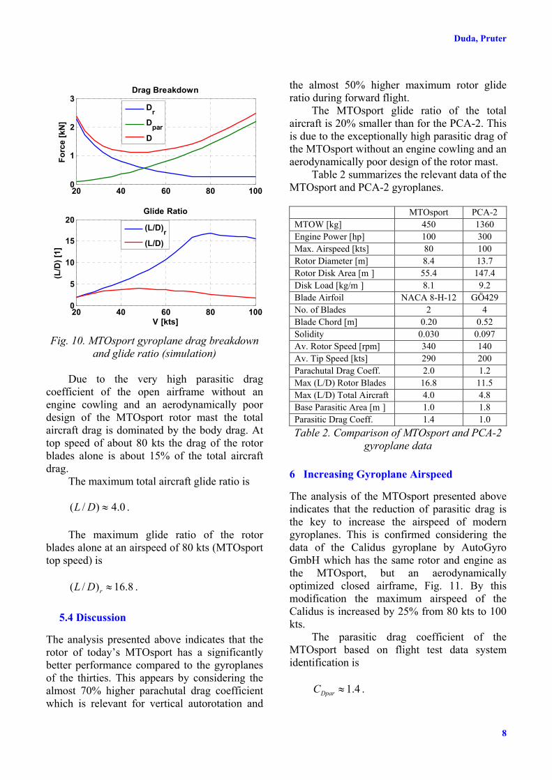
The steady state data simulation of the simulated MTOsport rotor during forward flight at airspeed of 65 kts is presented in Table 1.
Rotor vertical force NZr 4420| Rotor horizontal force NX r 112�| Rotor rotational speed rpmr 338|Z Rotor downwash velocity smwDW /7.0|Rotor plane angle of attack deg2.3|rD Table 1. MTOsport simulation data at an
airspeed of 65 kts
The horizontal and vertical rotor forces for one revolution are presented in Fig. 9. Both forces are oscillating periodically two times per revolution due to the two rotor blades which means about 11 Hz in this case. The vertical force amplitude is about 600 N which is reducing the flight comfort noticeable.
0 90 180 270 360
4
4.5
5
Z r [kN
]
Rotor Vertical Force
0 90 180 270 360
-0.2
-0.1
0
X r [kN
]
Rotor Horizontal Force
\rbl [deg] Fig. 9. MTOsport horizontal and vertical rotor
forces at an airspeed of 65 kts
5.3 Glide Ratio (L/D)
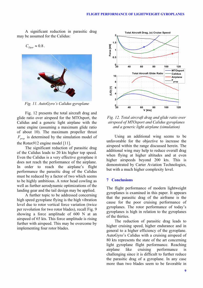
Fig. 10 presents the drag breakdown and the glide ratio of the MTOsport rotor blades alone and of the total aircraft.
Duda, Pruter
8
20 40 60 80 1000
1
2
3
Forc
e [k
N]
Drag Breakdown
DrDparD
20 40 60 80 1000
5
10
15
20
V [kts]
(L/D
) [1]
Glide Ratio
(L/D)r(L/D)
Fig. 10. MTOsport gyroplane drag breakdown
and glide ratio (simulation)
Due to the very high parasitic drag coefficient of the open airframe without an engine cowling and an aerodynamically poor design of the MTOsport rotor mast the total aircraft drag is dominated by the body drag. At top speed of about 80 kts the drag of the rotor blades alone is about 15% of the total aircraft drag.
The maximum total aircraft glide ratio is
0.4)/( |DL . The maximum glide ratio of the rotor
blades alone at an airspeed of 80 kts (MTOsport top speed) is
8.16)/( |rDL .
5.4 Discussion
The analysis presented above indicates that the rotor of today’s MTOsport has a significantly better performance compared to the gyroplanes of the thirties. This appears by considering the almost 70% higher parachutal drag coefficient which is relevant for vertical autorotation and
the almost 50% higher maximum rotor glide ratio during forward flight.
The MTOsport glide ratio of the total aircraft is 20% smaller than for the PCA-2. This is due to the exceptionally high parasitic drag of the MTOsport without an engine cowling and an aerodynamically poor design of the rotor mast.
Table 2 summarizes the relevant data of the MTOsport and PCA-2 gyroplanes.
MTOsport PCA-2 MTOW [kg] 450 1360 Engine Power [hp] 100 300 Max. Airspeed [kts] 80 100 Rotor Diameter [m] 8.4 13.7 Rotor Disk Area [m ] 55.4 147.4 Disk Load [kg/m ] 8.1 9.2 Blade Airfoil NACA 8-H-12 GÖ429 No. of Blades 2 4 Blade Chord [m] 0.20 0.52 Solidity 0.030 0.097 Av. Rotor Speed [rpm] 340 140 Av. Tip Speed [kts] 290 200 Parachutal Drag Coeff. 2.0 1.2 Max (L/D) Rotor Blades 16.8 11.5 Max (L/D) Total Aircraft 4.0 4.8 Base Parasitic Area [m ] 1.0 1.8 Parasitic Drag Coeff. 1.4 1.0 Table 2. Comparison of MTOsport and PCA-2
gyroplane data
6 Increasing Gyroplane Airspeed
The analysis of the MTOsport presented above indicates that the reduction of parasitic drag is the key to increase the airspeed of modern gyroplanes. This is confirmed considering the data of the Calidus gyroplane by AutoGyro GmbH which has the same rotor and engine as the MTOsport, but an aerodynamically optimized closed airframe, Fig. 11. By this modification the maximum airspeed of the Calidus is increased by 25% from 80 kts to 100 kts.
The parasitic drag coefficient of the MTOsport based on flight test data system identification is
4.1|DparC .
9
FLIGHT PERFORMANCE OF LIGHTWEIGHT GYROPLANES
A significant reduction in parasitic drag may be assumed for the Calidus:
8.0|DparC .
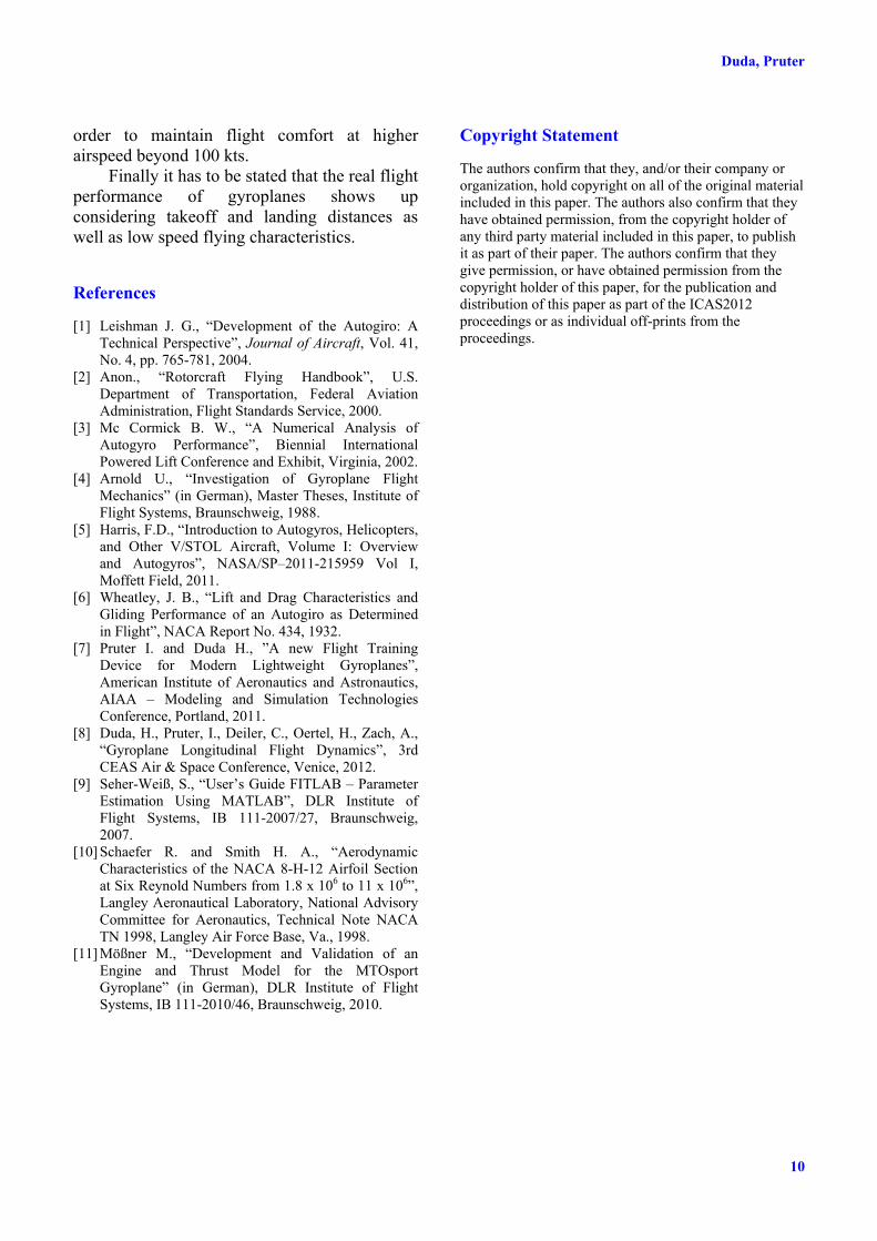
Fig. 11. AutoGyro’s Calidus gyroplane Fig. 12 presents the total aircraft drag and
glide ratio over airspeed for the MTOsport, the Calidus and a generic light airplane with the same engine (assuming a maximum glide ratio of about 10). The maximum propeller thrust
propF is determined by the simulation model of the Rotax912 engine model [11].
The significant reduction of parasitic drag of the Calidus leads to 20 kts higher top speed. Even the Calidus is a very effective gyroplane it does not reach the performance of the airplane. In order to reach the airplane’s flight performance the parasitic drag of the Calidus must be reduced by a factor of two which seems to be highly ambitious. A rotor head cowling as well as further aerodynamic optimizations of the landing gear and the tail design may be applied.
A further topic to be addressed concerning high speed gyroplane flying is the high vibration level due to rotor vertical force variation (twice per revolution for two rotor blades), recall Fig. 9 showing a force amplitude of 600 N at an airspeed of 65 kts. This force amplitude is rising further with airspeed. This may be overcome by implementing four rotor blades.
20 40 60 80 100 1200
0.5
1
1.5
2
Forc
e [k
N]
Total Aircraft Drag, (o) Cruise Speed
20 40 60 80 100 1200
2
4
6
8
10Total Aircraft Glide Ratio
(L/D
) [1]
V [kts]
MTOsportCalidusAirplaneFprop
Fig. 12. Total aircraft drag and glide ratio over airspeed of MTOsport and Calidus gyroplanes
and a generic light airplane (simulation)
Using an additional wing seems to be unfavorable for the objective to increase the airspeed within the range discussed herein. The additional wing may help to reduce overall drag when flying at higher altitudes and at even higher airspeeds beyond 200 kts. This is demonstrated by Carter Aviation Technologies, but with a much higher complexity level.
7 Conclusions
The flight performance of modern lightweight gyroplanes is examined in this paper. It appears that the parasitic drag of the airframe is the cause for the poor cruising performance of gyroplanes. The rotor performance of today’s gyroplanes is high in relation to the gyroplanes of the thirties.
The reduction of parasitic drag leads to higher cruising speed, higher endurance and in general to a higher efficiency of the gyroplane. AutoGyro’s Calidus with a cruising airspeed of 80 kts represents the state of the art concerning light gyroplane flight performance. Reaching airplane like cruising performance is challenging since it is difficult to further reduce the parasitic drag of a gyroplane. In any case more than two blades seem to be favorable in
Duda, Pruter
10
order to maintain flight comfort at higher airspeed beyond 100 kts.
Finally it has to be stated that the real flight performance of gyroplanes shows up considering takeoff and landing distances as well as low speed flying characteristics.
References
[1] Leishman J. G., “Development of the Autogiro: A Technical Perspective”, Journal of Aircraft, Vol. 41, No. 4, pp. 765-781, 2004.
[2] Anon., “Rotorcraft Flying Handbook”, U.S. Department of Transportation, Federal Aviation Administration, Flight Standards Service, 2000.
[3] Mc Cormick B. W., “A Numerical Analysis of Autogyro Performance”, Biennial International Powered Lift Conference and Exhibit, Virginia, 2002.
[4] Arnold U., “Investigation of Gyroplane Flight Mechanics” (in German), Master Theses, Institute of Flight Systems, Braunschweig, 1988.
[5] Harris, F.D., “Introduction to Autogyros, Helicopters, and Other V/STOL Aircraft, Volume I: Overview and Autogyros”, NASA/SP–2011-215959 Vol I, Moffett Field, 2011.
[6] Wheatley, J. B., “Lift and Drag Characteristics and Gliding Performance of an Autogiro as Determined in Flight”, NACA Report No. 434, 1932.
[7] Pruter I. and Duda H., ”A new Flight Training Device for Modern Lightweight Gyroplanes”, American Institute of Aeronautics and Astronautics, AIAA – Modeling and Simulation Technologies Conference, Portland, 2011.
[8] Duda, H., Pruter, I., Deiler, C., Oertel, H., Zach, A., “Gyroplane Longitudinal Flight Dynamics”, 3rd CEAS Air & Space Conference, Venice, 2012.
[9] Seher-Weiß, S., “User’s Guide FITLAB – Parameter Estimation Using MATLAB”, DLR Institute of Flight Systems, IB 111-2007/27, Braunschweig, 2007.
[10] Schaefer R. and Smith H. A., “Aerodynamic Characteristics of the NACA 8-H-12 Airfoil Section at Six Reynold Numbers from 1.8 x 10⁶ to 11 x 106”, Langley Aeronautical Laboratory, National Advisory Committee for Aeronautics, Technical Note NACA TN 1998, Langley Air Force Base, Va., 1998.
[11] Mößner M., “Development and Validation of an Engine and Thrust Model for the MTOsport Gyroplane” (in German), DLR Institute of Flight Systems, IB 111-2010/46, Braunschweig, 2010.
Copyright Statement
The authors confirm that they, and/or their company or organization, hold copyright on all of the original material included in this paper. The authors also confirm that they have obtained permission, from the copyright holder of any third party material included in this paper, to publish it as part of their paper. The authors confirm that they give permission, or have obtained permission from the copyright holder of this paper, for the publication and distribution of this paper as part of the ICAS2012 proceedings or as individual off-prints from the proceedings.