Embed Size (px)
Citation preview

Flight Control of Sliding Arm Quadcopter withDynamic Structural Parameters
Rumit Kumar1, Aditya M. Deshpande1, James Z. Wells1, and Manish Kumar2
Abstract— The conceptual design and flight controller of anovel kind of quadcopter are presented. This design is capableof morphing the shape of the UAV during flight to achieveposition and attitude control. We consider a dynamic center ofgravity (CoG) which causes continuous variation in a momentof inertia (MoI) parameters of the UAV in this design. Thesedynamic structural parameters play a vital role in the stabilityand control of the system. The length of quadcopter arms is avariable parameter, and it is actuated using attitude feedback-based control law. The MoI parameters are computed in real-time and incorporated in the equations of motion of the system.The UAV utilizes the angular motion of propellers and variablequadcopter arm lengths for position and navigation control.The movement space of the CoG is a design parameter and itis bounded by actuator limitations and stability requirements ofthe system. A detailed information on equations of motion, flightcontroller design and possible applications of this system areprovided. Further, the proposed shape-changing UAV system isevaluated by comparative numerical simulations for way pointnavigation mission and complex trajectory tracking.
I. Introduction
Multirotor applications in the civilian domain have gainedextensive popularity over the past decade. Several companiesand researchers are coming up with new designs basedon evolving operational requirements. This rapidly growingmarket demands for innovative design advances to makeUAV operations more reliable and safer during the fight.The quadcopters are among the most popular platforms inthis space and they come with different weight range basedon the payload and endurance requirements during flight.The evolving drone operational requirements pose immensechallenges for aircraft designers and flight control engineers.Tethered UAV configurations, variable blade pitch quad-copters, engine-powered UAVs, tail-sitters, morphologicalaerial platforms, and tilt-rotor quadcopters are popular namesamong unique aircraft designs. Here, we discuss a briefoverview of these aircraft designs to highlight the diversityand implications of various aerial platforms.
In tethered quadcopters, long-endurance flights can beachieved by using a taut cable to deploy the UAV fromground [1]. This cable is responsible for continuous powersupply to the UAV during flight. The variable blade pitchquadcopter is another interesting design as it can achieve
1R. Kumar, A. M. Deshpande, J. Z. Wells are graduate studentsat Cooperative Distributed Systems Lab at the University of Cincin-nati, Ohio 45221, USA, Email:(kumarrt, deshpaad, wells2jz)@mail.uc.edu
2 M. Kumar is Professor at the Department of Mechanical and Ma-terials Engineering at the University of Cincinnati, Ohio 45221, USA,Email:[email protected]
*Manuscript under review
aggressive and inverted flight modes [2]. Unlike conventionalmultirotor, all propellers in a variable blade pitch UAV spinat the same angular speed whereas navigation is achieved byvarying the rotor blade pitch based on the control law. Thevariable pitch quadcopter utilizes the main motor for drivingthe propellers and four additional servo motors for control-ling the blade pitch during flight. Sheng et al. [3] discussedthe control and optimization for variable pitch quadcopterand Pang et al. in [4] showed a design of gasoline-enginepowered variable-pitch quadcopter. The concept of variablepitch quad tilt-rotor (VPQTR) aircraft is discussed in [5].Tail-sitter UAVs are also popular as they can take off andland like multi-rotors and execute missions like fixed-wingaircraft. The notable work on tail-sitter UAVs was presentedin [6] and [7].
Falanga et al. in [8] presented morphing quadcopter designwhich can change shape, squeeze and fly through narrowspaces. This quadcopter can transition between X, T, H,O morphology configurations. The shape-changing featureleads to adaptive morphology in UAVs. This extends theflight operations envelope of unmanned aerial systems in anuncertain environment. Aerial manipulation using a shape-changing aerial vehicle is discussed in [9] and [10]. TheDRAGON can achieve shape transformation in-flight usingmultiple links and highlight the feasibility of aerial ma-nipulation [10]. Bucki et al. presented a novel passivelymorphing design and control of quadrotor [11]. This de-sign focused on maneuver such as traversal of the vehiclethrough small gaps. This design used sprung hinges onthe UAV arms which had downward foldable degree offreedom when low thrust commands were applied. The tilt-rotor quadcopters are over actuated systems with eight servoinputs and provide independent control over each degree offreedom in the system [12]. So far, the additional servo inputsin the unmanned aerial systems have been exploited fordeveloping unique morphological configurations, and aerialmanipulation. However, we propose a new design aspectby providing active control of the structural parameters ofthe UAV. The primary objective is to achieve position andattitude control of the UAV by varying the quadcopter armlengths alone or in combination with rotor speeds.
The structural parameter variation can induce body torqueswhich can be exploited to enable UAV navigation by devel-oping appropriate attitude feedback control laws. Change inUAV shape results in variations of Center of Gravity (CoG)and Moment of Inertia (MoI) of the system. The structuralparameters are computed in real-time to develop an accuratedynamic model. These design changes in vehicle will be
arX
iv:2
004.
1292
0v1
[cs
.RO
] 2
7 A
pr 2
020

useful in augmenting the operational capabilities of the UAVsfor different applications such as aerial transportation andheavy payload delivery. There is always a design trade-off
between the stability and maneuverability in aerial vehicles.The stability is an important aspect for a large size multirotorUAV. It is difficult to achieve the required control bandwidthin large drones with big propellers by using the conventionalmotor mixer technique [13]. So, the method of control via-structural parameter variation will prove useful for largesize aerial platforms. Similarly, fault-tolerant control in caseof a propeller failure is another aspect where this designwill prove useful. It has been reported that the tilt-rotorquadcopter can achieve fault-tolerant capabilities in case of apropeller failure during flight [14], [15]. They can completethe flight mission with three functional propellers. Fault toler-ance was achieved by the flight controller and the structuralreconfiguration in this design. The flight controller recon-figuration logic was implemented at a software level and apassive structural reconfiguration was achieved by changingthe quadcopter arm length [16]. However, these previousworks do not account for continuous control of structuralreconfiguration parameters. Although work in [17] presenteda quadrotor design with variable arm length configuration,the control strategy was constrained for symmetric morphingof the drone. In this paper, we address this limitation by theshape-changing quadcopter design as shown in figure-1. Thecontinuous control of structural parameters is an importantadditional capability for control large size drones and forachieving fault-tolerant control in case of propeller failure.
II. Design and DynamicModel
In this section, the design and mathematical dynamicmodel of the proposed quadcopter are presented. We considera plus (+) configuration quadcopter as shown in figure 1and the sliding arm mechanism is shown in figure 2. In thisdesign, the system has two long arms with a linear degree offreedom and each arm can slide through the guide bearings.Each arm is independently actuated using a belt-driven servomotor as shown in figure 2. The main motor and propellercombination is present at the ends of each arm such thatmotor 1 and 3 are on one arm and motor 2 and 4 are onthe other arm to yield a quadcopter configuration. The totallength of each arm is constant such that if one rotor movestowards the quadcopter center, the opposite rotor would bemoving away and vice-versa. The linear displacement ofquadcopter arm with motors 1 and 3 is denoted by ∆Xl.Similarly, the linear displacement of quadcopter arm withmotors 2 and 4 is denoted by ∆Yl. The system has fourmotor-propeller pairs and two additional servo motors foractuating the arms. The two arms of this quadcopter havevertical offset which enables their collision-free movementin different planes during the UAV operation.
As discussed earlier, the shape of the sliding arm UAVchanges based on the attitude feedback control law. Hence,there is a requirement of a parameter estimation module tocompute the MoI matrix in real-time for accurate dynamicmodeling and controller development for the system [8]. The
Fig. 1: Sliding Arm Quadcopter UAV Design
Fig. 2: Sliding Arm Mechanism
motion of the UAV is referred w. r. t. the world-frame (E)and the body-fixed frame (B) moves with the quadcopter.The nominal configuration is defined when the length ofall quadcopter arms are equal. In nominal configuration, thesystem is identical to a hovering conventional quadcopter,the origin of the body frame (B) coincides with the {CoG}frame and the geometric center of the UAV. In the slidingarm design the {CoG} frame and the geometric center ofthe system can move to a different position in horizontalplane due to structural asymmetry. But, the movement of the{CoG} frame does not effect the translational dynamics ofthe system as shown in (1) and (2).
xyz
=cψcθ cψsθsφ − sψcφ cψsθcφ + sψsφsψcθ sψsθsφ + cψcφ sψsθcφ − cψsφ−sθ cθsφ cθcφ
uvw
(1)
uvw
= 1m
00
4∑i=1
Fi
−−gsθgcθsφgcθcφ
+rv − qwpw − ruqu − pv
(2)
Here, m and g denote mass of the UAV and acceleration dueto gravity. The sine and cosine angle terms are representedas s(.) and c(.) respectively. [u, v,w]T is the velocity vectorin B and Z − Y − X Euler angle transformation is utilized tocompute vehicle states in E. [x, y, z]T is the position vectorof B in E. The total thrust force generated by the propellersis given by ΣFi,∀i ∈ {1, 2, 3, 4}. The body rate vector isrepresented by [p, q, r]T in the {CoG} frame.
The rotational dynamics are described similar to [18] bysolving for torque in {CoG} frame. A parameter estimation

Fig. 3: Axes notation for rotational dynamics.Note: {CoG}ri ≡ ({CoG}rxi ,
{CoG} ryi ),∀i ∈ {1, 2, 3, 4}
module is used to estimate the instantaneous MoI matrix({CoG}J) for the UAV. Firstly, {CoG}r vector is computed in B.Further, the MoI of each UAV component is transformed to{CoG} frame using parallel-axes theorem. The motors andpropellers are modelled as cylinders. Similarly, the quad-copter arms and the central body of the UAV are modelledas cuboids. A detailed discussion on skew-symmetric MoImatrix ({CoG}J) computation is presented in reference [8]. Itincludes computation of {CoG}r vector of the system in B, andMoI of each component of the UAV such as {body}J, {arm}J,{motor}J, and {rotor}J. Further, the {CoG}J matrix is obtained bytransforming the MoI of the components in {CoG} [8]. Therotational dynamic equations are given by (3).
{CoG}J
pqr
=
4∑i=1
{CoG}ryi Fi
−4∑
i=1
{CoG}rxi Fi
4∑i=1
(−1)iMi
−
pqr
×{CoG} J
pqr
(3)
Here, Fi, and Mi, ∀i ∈ {1, 2, 3, 4} are the force and momentproduced by the respective propeller and they are directlyproportional to the squared angular speed (ω) of the propelleras described in [19]. The axes notation for the rotationaldynamics are highlighted in figure 3. It should be noted thatthe equation (3) has components of torque from all motorsfor each rotational degree of freedom in the UAV. The torqueproduced by any motor about {CoG} frame is dependent on{CoG}r vector and angular speed (ω) of the motor. The Eulerangles for orientation representation can be computed byintegrating the standard Euler angle rate equation [19]. Itis considered that the body frame B and {CoG} frame willhave the same orientation during flight [18]. Thus, the bodyrates [p, q, r]T can be directly measured using an inertialmeasurement unit (IMU) sensor which can be utilized toestimate the orientation of the system.
III. Controller Development
In this section, the controller development strategy forthe sliding arm quadcopter is presented. This system hassix motor inputs. The dynamic model presented in section-II is used for controller design. The control system of thesliding arm UAV is based on the conventional cascaded looparchitecture. It consists of an outer position control modulewhich generates orientation commands for the inner attitudecontroller. An additional parameter estimation module isimplemented for updating the MoI-matrix to account forchange in the shape of UAV.
A. Position Control
The position control is the outer loop of the controllerand it generates attitude set point commands for the innerattitude controller of the UAV. The position state feedbackin world frame is utilized to compute position and velocityerrors (ex, ey, ez, ex, ey, ez). This information is utilized bythe PID controller loop to compute desired accelerationscommands ri
des;∀i ∈ {x, y, z} for the UAV as shown in (4).The acceleration due to gravity is compensated as a feed-forward term in the zE-controller.
rxd = kpx ex + kix
∫exdt + kdx ex
ryd = kpy ey + kiy
∫eydt + kdy ey (4)
rzd = kpz ez + kiz
∫ezdt + kdz ez + g
Here, kpi , kii , and kdi ∀i ∈ {x, y, z} are the proportional,integral and derivative gains for the position controller. Therotor angular speed required for individual propeller motorsnecessary for hovering and motion along the zE−axis is givenby ωh as shown in (5).
ωh =
√mrz
d
4k f(5)
The desired accelerations along xEyE-axes from (4) are usedto compute the attitude set point commands. The pitch androll angle set point commands for the UAV are representedas θd and φd respectively as shown in [19].
φd =rx
d sinψd − rydcosψd
g(6)
θd =rx
dcosψd − ryd sinψd
g(7)
where, ψd is the desired yaw angle for the system. Theattitude set point commands are sent to the attitude controller.
B. Attitude Control
In conventional quadcopter, the attitude control loop gen-erates rotor angular speed commands ωi,∀i ∈ {1, 2, 3, 4} inthe form of PWM signals to the UAV motors. However,the sliding arm quadcopter design has two additional servoinputs for actuating the quadcopter arms. The linear displace-ment of quadcopter arms are represented by ∆Xl and ∆Yl.

The attitude set point commands are given by (6) and (7)and the attitude state feedback is utilized to compute theerror (eφ, eθ, eψ, ep, eq, er) in vehicle orientation with respectto the attitude commands. This information is utilized bythe PID controller to compute the change in the angularspeed (∆ωi,∀i ∈ {φ, θ, ψ}) of the rotors and quadcopter armdisplacement (∆Xl,∆Yl) as shown in (9).
∆ωi = kpi ei + kii
∫eidt + kdi ei; ∀i ∈ {φ, θ, ψ}
∆Xl = kplθeθ + kilθ
∫eθdt + kdlθ
eθ (8)
∆Yl = kplφeφ + kilφ
∫eφdt + kdlφ
eφ
Here, kpi , kii , and kdi ∀i ∈ {φ, θ, ψ, lθ, lφ} are the proportional,integral and derivative gains for the attitude controller. Theangular speeds outputs (∆ωi,∀i ∈ {φ, θ, ψ}) are passed tothe motor mixing module to generate rotor commands asshown in [19]. Similarly, the linear displacement commands(∆Xl,∆Yl) are used in servo motors governing the slidingmotion of the quadcopter arms. The complete signal flowand control architecture of the sliding arm UAV is shownin figure 4. The servo motors for actuating the quadcopterarms are modelled by classic second order transfer functionas shown in equation (9).
G(s) =ω2
n
s2 + 2ζωn + ω2n
(9)
In the actual system, a servo motor with higher bandwidthwould be necessary for faster actuation of quadcopter arms.There are commercially available digital servo motors withan operational frequency of up to 15rad/s which would bean ideal choice for this application [20].
IV. Numerical Simulations and Results
In this section, the proposed controller is validated bynumerical simulations. The mathematical model of the UAVand controller are developed in MATLAB and SimulinkR2017a. Two types of numerical simulations were consideredin this work. The parameters used in the simulations aretotal mass of the system m = 1.56kg, nominal quadcopterarm length l = 0.25m, thrust and moment coefficients for thepropellers are k f = 2.2e−4Ns/rad, and km = 5.4e−6Ns/radrespectively and the MoI-matrix is a variable quantity. The
Fig. 4: Control Architecture
first simulation shows the performance of the system ina conventional way point navigation mission. The secondsimulation shows the performance of the UAV for complextrajectory tracking in the presence of sensory noise.
A. Way Point Navigation Simulation
The UAV is initialized at the origin and commanded tovisit a predefined set of way points given by {(xd, yd, zd)} :{(1, 1, 1), (1, 2, 2), (2, 2, 1), (2, 3, 2)}. The dimensions are inmeters. The objective of this study is to assess the perfor-mance of the control scheme and novel quadcopter designfor two cases: (i) the attitude controller is governed by thecombination of variation in propeller rpm (∆ωi,∀i ∈ {φ, θ, ψ})and quadcopter sliding arm control (∆Xl,∆Yl) simultaneously(called ‘Conventional + Sliding Arm Quad’ in the figures);(ii) the attitude controller is solely governed by the quad-copter sliding arm (∆Xl,∆Yl) and propeller rpm are not variedexcept for thrust and yaw control such that (∆ωφ = ∆ωθ = 0)(called ‘Sliding Arm Quad Only’ in the figures). The three-dimensional trajectory of the UAV is shown in figure 5.The UAV can visit the set of way points successfully inboth cases. Figure 6 shows the variation of Euler anglesduring flight. It can be seen that sliding arm quadcopter hashigher transient peaks while changing direction across waypoint. However, the combination based controller achievessmoother transition across way points. Figure 7 shows thevariation in the angular speed of the propellers during flight.Figure 8 shows the variation in quadcopter sliding arm lengthfor both the cases. As observed earlier, the sliding armcontrol has larger transient peaks while functioning alone forcontrolling the attitude of the UAV. However, the transientpeaks are minimized in the combination based controller.The overall performance of both systems is very similar,but it is interesting to note that the proposed system cannavigate just by changing the shape of the UAV duringflight. The flying characteristics are also very comparableto the conventional quadcopter. This can be attributed to thedynamic nature of the center of gravity resulting in controltorques for navigating the UAV. The sliding arm quadcopterdesign is useful in the absence of the conventional rotorangular speed controller such as for the large size multirotors.
B. Trajectory Tracking Simulation
Here, the performance of the system is evaluated similarto the previous case. The UAV is commanded to tracka figure-eight trajectory. The equations governing the de-sired flight path are the same as described in [21]. Thesimulation is performed with uncertainties in the roll andpitch angles of the UAV. A uniformly distributed randomnoise is considered in the range of −2 to +2 degrees. Thesimulation is performed for three cases: (i) a conventionalquadcopter configuration with no sliding arm functionality(called ‘Conventional Quad’ in the figures); (ii) the attitudecontroller is solely governed by the quadcopter sliding arm(∆Xl,∆Yl) and (∆ωφ = ∆ωθ = 0); (iii) the attitude controlleris governed by the combination of variation in propeller rpmand quadcopter sliding arm control simultaneously. Figure
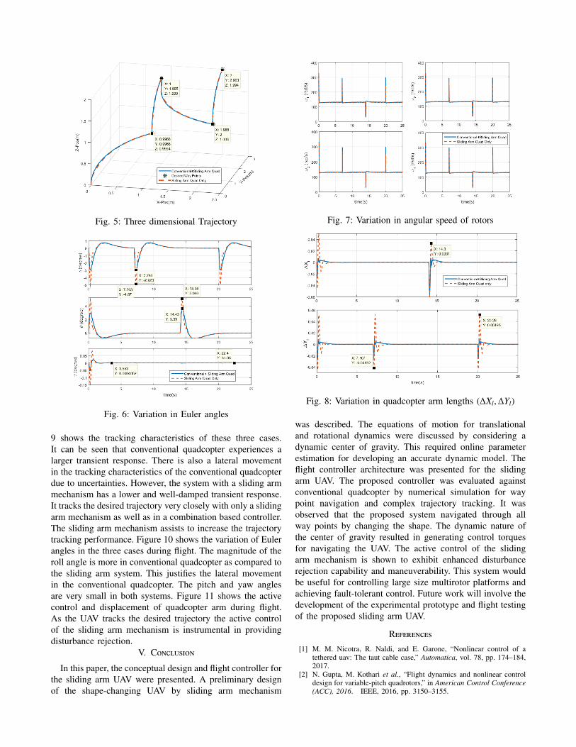
Fig. 5: Three dimensional Trajectory
Fig. 6: Variation in Euler angles
9 shows the tracking characteristics of these three cases.It can be seen that conventional quadcopter experiences alarger transient response. There is also a lateral movementin the tracking characteristics of the conventional quadcopterdue to uncertainties. However, the system with a sliding armmechanism has a lower and well-damped transient response.It tracks the desired trajectory very closely with only a slidingarm mechanism as well as in a combination based controller.The sliding arm mechanism assists to increase the trajectorytracking performance. Figure 10 shows the variation of Eulerangles in the three cases during flight. The magnitude of theroll angle is more in conventional quadcopter as compared tothe sliding arm system. This justifies the lateral movementin the conventional quadcopter. The pitch and yaw anglesare very small in both systems. Figure 11 shows the activecontrol and displacement of quadcopter arm during flight.As the UAV tracks the desired trajectory the active controlof the sliding arm mechanism is instrumental in providingdisturbance rejection.
V. Conclusion
In this paper, the conceptual design and flight controller forthe sliding arm UAV were presented. A preliminary designof the shape-changing UAV by sliding arm mechanism
Fig. 7: Variation in angular speed of rotors
Fig. 8: Variation in quadcopter arm lengths (∆Xl,∆Yl)
was described. The equations of motion for translationaland rotational dynamics were discussed by considering adynamic center of gravity. This required online parameterestimation for developing an accurate dynamic model. Theflight controller architecture was presented for the slidingarm UAV. The proposed controller was evaluated againstconventional quadcopter by numerical simulation for waypoint navigation and complex trajectory tracking. It wasobserved that the proposed system navigated through allway points by changing the shape. The dynamic nature ofthe center of gravity resulted in generating control torquesfor navigating the UAV. The active control of the slidingarm mechanism is shown to exhibit enhanced disturbancerejection capability and maneuverability. This system wouldbe useful for controlling large size multirotor platforms andachieving fault-tolerant control. Future work will involve thedevelopment of the experimental prototype and flight testingof the proposed sliding arm UAV.
References
[1] M. M. Nicotra, R. Naldi, and E. Garone, “Nonlinear control of atethered uav: The taut cable case,” Automatica, vol. 78, pp. 174–184,2017.
[2] N. Gupta, M. Kothari et al., “Flight dynamics and nonlinear controldesign for variable-pitch quadrotors,” in American Control Conference(ACC), 2016. IEEE, 2016, pp. 3150–3155.

Fig. 9: Two dimensional Trajectory
Fig. 10: Variation in Euler angles
Fig. 11: Variation in quadcopter arm lengths (∆Xl,∆Yl)
[3] S. Sheng and C. Sun, “Control and optimization of a variable-pitchquadrotor with minimum power consumption,” Energies, vol. 9, no. 4,p. 232, 2016.
[4] T. Pang, K. Peng, F. Lin, and B. M. Chen, “Towards long-enduranceflight: Design and implementation of a variable-pitch gasoline-enginequadrotor,” in Control and Automation (ICCA), 2016 12th IEEEInternational Conference on. IEEE, 2016, pp. 767–772.
[5] G. Ferrarese, F. Giulietti, and G. Avanzini, “Modeling and simulationof a quad-tilt rotor aircraft,” IFAC Proceedings Volumes, vol. 46,no. 30, pp. 64–70, 2013.
[6] S. Swarnkar, H. Parwana, M. Kothari, and A. Abhishek, “Biplane-quadrotor tail-sitter uav: Flight dynamics and control,” Journal ofGuidance, Control, and Dynamics, vol. 41, no. 5, pp. 1049–1067,2018.
[7] R. Ritz and R. DAndrea, “A global strategy for tailsitter hover control,”in Robotics Research. Springer, 2018, pp. 21–37.
[8] D. Falanga, K. Kleber, S. Mintchev, D. Floreano, and D. Scaramuzza,“The foldable drone: A morphing quadrotor that can squeeze and fly,”IEEE Robotics and Automation Letters, vol. 4, no. 2, pp. 209–216,April 2019.
[9] N. Zhao, Y. Luo, H. Deng, and Y. Shen, “The deformable quad-rotor: Design, kinematics and dynamics characterization, and flightperformance validation,” in Intelligent Robots and Systems (IROS),2017 IEEE/RSJ International Conference on. IEEE, 2017, pp. 2391–2396.
[10] M. Zhao, T. Anzai, F. Shi, X. Chen, K. Okada, and M. Inaba,“Design, modeling, and control of an aerial robot dragon: A dual-rotor-embedded multilink robot with the ability of multi-degree-of-freedomaerial transformation,” IEEE Robotics and Automation Letters, vol. 3,no. 2, pp. 1176–1183, 2018.
[11] N. Bucki and M. W. Mueller, “Design and control of a passivelymorphing quadcopter,” in 2019 International Conference on Roboticsand Automation (ICRA). IEEE, 2019, pp. 9116–9122.
[12] S. Sridhar, G. Gupta, R. Kumar, M. Kumar, and K. Cohen, “Tilt-rotor quadcopter xplored: Hardware based dynamics, smart slidingmode controller, attitude hold & wind disturbance scenarios,” in 2019American Control Conference (ACC). IEEE, 2019, pp. 2005–2010.
[13] Y. Mulgaonkar, M. Whitzer, B. Morgan, C. M. Kroninger, A. M.Harrington, and V. Kumar, “Power and weight considerations in small,agile quadrotors,” in Micro-and Nanotechnology Sensors, Systems, andApplications VI, vol. 9083. International Society for Optics andPhotonics, 2014, p. 90831Q.
[14] A. Nemati, R. Kumar, and M. Kumar, “Stabilizing and control oftilting-rotor quadcopter in case of a propeller failure,” in ASME 2016Dynamic Systems and Control Conference. American Society ofMechanical Engineers, 2016, pp. V001T05A005–V001T05A005.
[15] R. Kumar, S. Sridhar, F. Cazaurang, K. Cohen, and M. Kumar,“Reconfigurable fault-tolerant tilt-rotor quadcopter system,” in ASME2018 Dynamic Systems and Control Conference. American Societyof Mechanical Engineers, 2018, pp. V003T37A008–V003T37A008.
[16] S. Sridhar, R. Kumar, K. Cohen, and M. Kumar, “Fault toleranceof a reconfigurable tilt-rotor quadcopter using sliding mode control,”in ASME 2018 Dynamic Systems and Control Conference. Amer-ican Society of Mechanical Engineers, 2018, pp. V003T37A009–V003T37A009.
[17] D. A. Wallace, “Dynamics and control of a quadrotor with activegeometric morphing,” Ph.D. dissertation, 2016.
[18] M. Zhao, K. Kawasaki, T. Anzai, X. Chen, S. Noda, F. Shi, K. Okada,and M. Inaba, “Transformable multirotor with two-dimensional mul-tilinks: Modeling, control, and whole-body aerial manipulation,” TheInternational Journal of Robotics Research, vol. 37, no. 9, pp. 1085–1112, 2018.
[19] N. Michael, D. Mellinger, Q. Lindsey, and V. Kumar, “The graspmultiple micro-uav testbed,” Robotics & Automation Magazine, IEEE,vol. 17, no. 3, pp. 56–65, 2010.
[20] “Servo Database,” https://servodatabase.com/, accessed: 2020-03-01.[21] R. Kumar, A. Nemati, M. Kumar, R. Sharma, K. Cohen, and F. Caza-
urang, “Tilting-rotor quadcopter for aggressive flight maneuvers usingdifferential flatness based flight controller,” in ASME 2017 DynamicSystems and Control Conference. American Society of MechanicalEngineers, 2017, pp. V003T39A006–V003T39A006.