Embed Size (px)
Citation preview

flFft1 I t\O.
AIRC?AFT CIRCtJLARS
!TATIONAL ADVISORY COLiITTEZ FOR ARON1<ICS
67
sJrEpJ5.IE 9.5 SEAPLATE (:r.::Is:i)
Winner o th 1927 Schneider Cup R:ce
ii.
c. uaI Aa.. Cnr!iee
Vashii.ton March, 1928
https://ntrs.nasa.gov/search.jsp?R=19930090650 2020-03-25T12:42:04+00:00Z
NATIONAL ADVISORY COITTEE FOR AERONAUTICS.
AIRCRAFT CIRCULAR NO. 67.
SUPERMARINE S.5 SEAPLANE (BRITI3H)*
Winner of the 1927 Schneider Cup Race.
As the winner of the 1927 race for •the Sclineider Seaplane
Trophy, and. as a potential holder of the world's speed record in
the near future, the Supermarine 3.5 with Napier "Lion" racing
engine is one of the most interesting of modern British aircraft,
and. it is with a good. deal of satisfaOtion that we are able to
place before our readers some particulars and a number of illus-
trations of its more interesting features. In his paper read.
recently before the R.Ae.S.& I.Ae.E., Mr. R. J. Mitchell, chief
engineer of the Supermarine Aviation Works, gave certain very I interesting figures relating to the S.5, but owing to the fact
that the results 0±' wind tunnel tests could not be published,
much information which would have been extremely interesting had
to be withheld. Nor are we. , for Obvious reasons, in a position
to give these here. For instance, the proportion of the total
drag represented by the fuselage, the floats, the float struts,
and the wings. But in the absence of such information it is per-
missible to speculate a little and to attempt to form, from,
other sources, an idea of the efficiency of a seaplane like the
3.5. Probably the "Everling Quantities'** afford the simplest
*From "Flight," February 16, 1928. **See "The Aircraft Engineer" (Technical Supplement to "Flight,
November 25, 1925, and February 24, 1927.
N.A.C.A. Aircraft Circular No. 67 2
available means of doing this, and of t1e three "Evening Quanti-
ties" it is, in this case, Darticulanly the "High-speed Figure
in which we are interested. In his article, Professor Evening
arrived at a value of the "High-speed Figure" of 40 as a sort of
theoretical maximum or "ideal," and pointed out that actual sea-
planes never attained this, but generally reached a value of about
half of the ideal." The Everling formula for "High-speed Figure"
is, for ground level flight such as would apply to a racing sea-
plane like the S..5
TI_ V3XF - 56,000 x N
where T) is the propeller efficiency, C the drag coefficient,
V the speed in km/hour, F the wing area in square meters and N
the brake horsepower of the engine. The brake horsepower of the
Napier engine may be assumed to be 875 HP. The wing area of the
S.5 is 115 sq.ft. = 10.68 sq.m, and if we assume a top speed of
300 M.P.H. (484 km/h), a figure which is probably somewhere very
near the actual speed on a straight-line course without previous
diving, we obtain a value of the "High-speed Figure" of
484 x 10.68 = 24.8. 56,000 x 875
This figure, of course, represents propeller efficiecy di-
vided by drag coefficient, and in the absence of accurate infor-
/ / mation concerning the sort of efficiencies that obtain in the ac-
tual seaplane we are again compelled to make the best guess we
N.ASC.A. Aircraft Circular N 0 . 87
3
can. Probably 80 per cent would be somewhere near the mark, and
if this is assumed as the value of r1 , the drag coefficient of the
whole seaplane at top speed is 0.032. As the German coefficients
are twice the value of ours, we obtain a drag coefficient, in
British "absolute" units, of 0.016. Admittedly we have had to
"guess" several of the figures upon which this value is based, but
probably it is at least approxiiTiately correct. When it is reem-
bered that the machipeis-a seaplane, and that therefore the float
landing gear must offer considerably i'eater drag than a land land-
ing gear, this low value of the drag is very remarkable.
Concerning the features of design which enabled this low drag
to be attained, Mr. Mitchell gave in his lecture, previously re-
ferred to, the main changes as between the S.4 and the S.5, and
the gain in speed which he attributed to the various changes. As
these figures were given in "Flight," of February 2, 1928, it is
not proposed to repeat them here Figure 1 will serve to show
how small are the frontal areas of fuselage and floats in the S.5,
and these and other illustrations give an idea of the care taken
in strea1ining unavoidable projections, and in fairing the vari-
ous surfaces into the fuselage. The brief specification at the
end of these notes contains the main available data relating to
the seaplane, and it is of interest to note that the "Wing Power"
is the highest of any plane ever described in "Flight," being no
less than 7.8 HP./sq.ft. (81.7 i-IP./sq.m).
N.A.C.A. Aircraft Circular !'T 0 . 67 4
Constructional Features
Although in a pure speed seaplane like the S.5, the aerody-
namic design is perhaps the more interesting, there are a number
of constructional features which are somewhat unusual, and which
were developed as a result of the special conditions to be met
with in,a high-speed plane. /
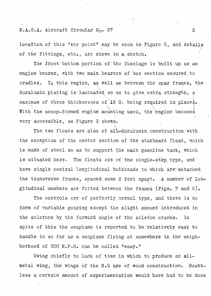
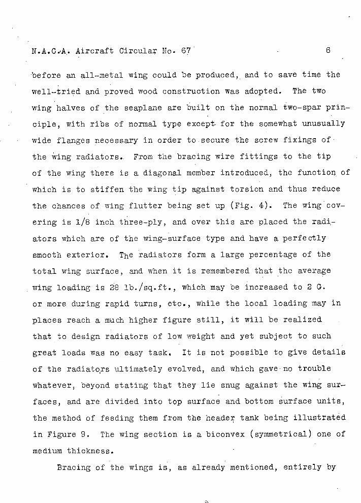
The fuselage of the S.5 is iilt entirely of metal (Fig. ),
chiefly duralumin, and an examination of the photograph of t,h
fuselage in skeleton will show that by using this material nd mak-
ing the body more or less a monocoque, a good, deal of space as,
saved so that it became possible to keep the cross section wn
to a minimum. In fact, the pilot sits on the floor, and a 1 his
shoulders touch the metal skin of the fuselage the only Opace lost
is represented by the thickness of the duralurnin skin! T1'ê method
of building up the fuselage is fairly, clear from Figure . Close-
ly spaced frames or formers of flat U-section give the form of the'
fuselage from point to point, while the Skin is made to serve in
the capacity of longerons, i.e., is a part of the streds-resist-
ing structure, reinforced here and there by fore-and-a±'t stringers.
In the forward portion there are specially strong frames for
the support of wing roots, landing gear struts and, at the top,
for the attachment of the anti-lift wire bracing. T1 e reason why
the latter point is one of great importance in the design is that
with the system of 'bracing used, this point serves to stabilize
the bracing of the whole seaplane, floats as well as'wings. The
N.A.C.A. Aircraft Circular N0 . 67 5
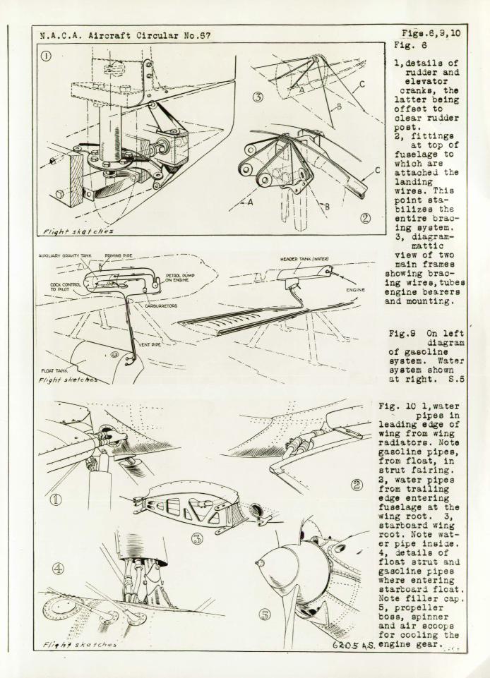
loaation of this "key point" may be seen in Figure 6, and details
of the fittings, etc., are shown in a sketch.
The front bottom portion of the fuselage is built up as an
eng.ne bearer, with two main bearers of box section secured to
cradles. I this region, as well as between the spar frames, the
duràlumin plating islaminated so as to give extra strength, a
maximum of three thicknesses of 18 G. being required in place.
With the scoop-formed engine mounting used, the engine become
very accessible, as Figure 3 shows.
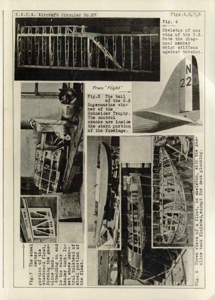
The two floats are also of a]i- .duralumin construction with
the exception of the center section of the starboard float, which
is made of steel so as to support the main gasoline tank, which
is situated here. The floats are of the single-step. type, and
have single central longitudinal bulkheads to which areat.tached
the transverse frames, spaced some .2 feet apart. A number of lon-
gitudinal members are fitted between the frames (Figs. 7 and 8).
The controls are of perfectly normal type, and there is no
form of variable gearing except tiie slight amount introduced in
the ailerons by the forward. angle of the aileron cranks. In
spite of this the seaplane is reported to be relatively easy to
handle in so far as a seaplane flying at somewhere in the neigh-
borhood of 300 M.P.H. can be called "easy."
Owing chiefly to lack of time in which to produce an all-
metal wing, the wings of the 8.5 are of wood. construction. Doubt.-
less a certain amount of experimentation would have had to be done
N.A.O.A.. Aircraft Circular No. 67
before an all-metal wing could be produced, and to save time the
well-tried and proved wood construction was adopted. The two
wing halves of the seaplane are built on the normal two-spar prin-
ciple, with ribs of normal type except . for the somewhat unusually
wide flanges necessary in order to.secure the screw fixings of
the wing radiators.. From the bracing wire fittings to the tip
of the wing there is a diagonal member introduced, the functioi of
which is to stiffen the wing tip against torsion and thus reduce
the chances of wing flutter being set up (Fig. 4). The wing cov-
ering is 1/8 inch three-ply, and over this are placed the radi •
-ators which are of the wing-surface type and have a perfectly
smooth exterior. The radiators form a large percentage of the
total wing surface, and when it is remembered that the average
wing loading is 28 lb./sq.ft., which may be increased to 2 G.
or more during rapid turns, etc., while the local loading may in
places reach a much higher figure still, it will be realized
that to design radiators of low weight and yet subject to such
great loads was no easy taskq It is not possible to give details
of the radiators ultimately evolved, and which gave' no trouble
whatever, beyond stating that they lie snug against the wing sur-
faces, and are divided into top surface and bottom surface units,
the method of feeding them from the header tank being illustrated
in Figure 9. The wing section is a biconvex (symmetrical) one of
medium thickness.
Bracing of the wings is, as already mentioned, entirely by
N.AIC.A. Aircraft Circular N 0 . 67 7
streamline wires, the top point of the fuselage deck fairing
serving to stabilize the whole bracing system of wings and floats.
Gasoline, Oil and Water Systems
With a fuselage of such very small cross-sectional area, the
subject of gasoline system, and lso to some extent oil and.
water system, became somewhat of a problem. It was found that
there would be no room in the fuselage for a gasoline tank, and
ultimately it was decided to place the main tank in the starboard
float. This has the advantage of lowering somewhat the center o±
gravity of the seaplane, and also the offset load on the starboard
side helped to counteract engine torque both when accelerating on
the water and in flight. The distance the gasoline had, to be
lifted Was, however, such that although in normal straight flight
the gasoline pump could handle it, during a steep turn, with cen-
trifugal force increasing the virtual distance, the engine would
be momentarily starved, and. so a small service tank was placed in
the fairing behind the starboard cylinder block. Thus during a
turn the engine takes its gasoline from the small tank, the
straight leg of the Schneider course giving the pump an opportu-
nity of filling this tank from the float tank before the next
turn was reached. The actual, gasoline system is diagrammetically
illustrated in Figure 9. The gasoline capacity, by the way, is
55 gallons.
Not only because of the high speed at which the Napier Liontt
N.A.CA. Aircraft Circular N 0 . 67
8
racing engines were run in the Schneider Race, butalso on ac-
count of the propeller gearing in the winning seaplane, which nat-
urally called for efficient lubrication, bearing in mind that
frictional losses in the gears must have amounted to a good many
horsepower, the oil system of the S.5 required rather close atten-
tion, . and the normal disposition was not regarded as being suffi-
cient. Consequently, the oil coolers were arranged along the
sides of the fuselage, where presumably they would be in the slip.
stream and always getting a good supplyof fresh, cool air.
Whether that position is the best possible is, perhaps, open to
doubt, since it Would seem likely that the. air does not follow
smoothly the surface of the fuselage but is considerably churned
up and also already heated to some extent by passing over the
engine. Be that as it may, that was the arrangement chosen, and
in the geared-engine seaplanes further cooling of the gears was
obtained by cutting openings in the cowlings over the cylinder
blocks.
The water system is, chiefly due to the use of wing radiators,
somewhat unusual, although not by any means particularly compli-
cated0 The water header tank is in the fairing behind the cen-
tral cylinder bank, and the water is led to the trailing edge
first, there dividing into two branches, of which one goes to the
top surface radiator arid one to the lower surface. After passing
tirough the radiators the water emerges at the inner end of the
leading edge and thence to the engine.
N.A.C.A. Aircraft Circular N0 .67
9.
The main characteristics of the 6.5 which it is permissible
to give are as follows:
Wing span
Wing chord
Wing area
Weight fully loaded
Wing loading
Gasoline (55 gallons)
Oil (5 gallons)
Pilot
26 ft. 9 in. (8.15 m)
5 " 0 " (l.25 m)
115 sq.ft. (10.68 sq.m)
3242l'o. (1475.00 kg)
28.2 lb./sq.ft. (138 kg/sq.m)
380.0 lb. (172.6 kg)
50.0 " ( 22.7 II)
170.0 " ( .77.3 ")
Evening "high—speed figure" (metric) 24.8
For obvious reasons performance figures cannot be given.
Some time in March the S.5 will be tested over Southampton Water
over a measured course, when it is hoped that it will beat the
worldt s record establihed by de Bernardi.
D
Aircraft Circlar o.6?
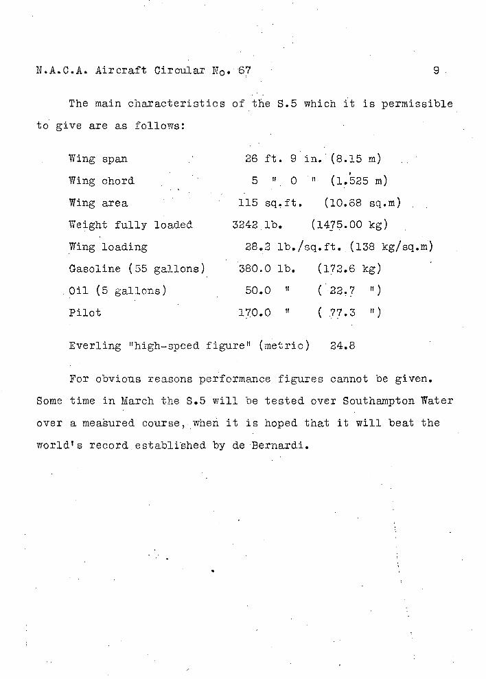
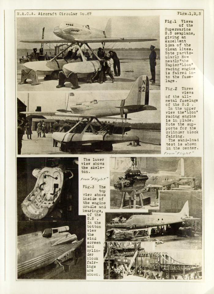
Figs .1, 2, 3
Fig.l Views of the
Supe rrrari ne S.5 seaplane, givIng an excellent ilea of the clean lines. ote parti.c-ularly ON
neatlythe Napier "Lion" racing engine is fairel to the fuse-lage.
'11
- ---- .--
4
;:
Fi g .2 Three views
of the all-retal fuselge cf the S. In the uer
7ieN the"Lion" racing engine is in lce. rote the sup-ports fcr the cylinier block fairing. The sani-].oaJ
test is shown in the center.
The lc.?..er vie.c s-ogs the akele-
:;' __ __
T1ei aholl - ir.81le of . : the engino -
I, i: j4: breer
--
.:ir- I ______
ck
a -eor/zf! uJrr. - i '-:':
: .:.. _
I
•i. 4
:1etcnof one -
From F//q,6/____
Fig.5 The tail of triS.5
.uperrnarine in-'er of the ohneider Trophy. - The aontrol _____ranka are inaiie the eterr orticn of the fugelage.
.A.C.A. Arcr-aft 1rcu1r ::.? ig .4,j, '/,
-I I I-4I-4 4) +) ' c:ioo 4) 4) -II
wo4-'.- 4 4)O +) ($44, O).O4)-4
4);: t,4 .4 4-) L.4-) .c: , 0d# s: '-4 ci 4).d p44' F-iO -IOu1
O4-'i oizo OO r4
c'- ..-i Q .-4 4, 4, r1 4-• 43!j i-44,
4 . 4-' 43))4) .•-4 :r. ms- 0 .4.L 4,i- 4)4'
/
44
I
4;,
A. :
'vII
II,( L4
AUXL&RT 6QAV1V TANK POJMNA PPC -HADA TANK (wA1R) -
!LA.C.A. Aircraft Circular No.? Figs .6,3,10
Fig. 8
1,details of rudder and elevator
cranks, the latter being offset to clear rudder post. 2, fittings
at top of fuselage to which are attache.i the landing wires. This point sta-bilizes the entire brac-ing system. 3, diagrait-
.at tic view of two main fraee
showing brac-ing trea, tubes engine bearers and mounting.
Fig.S On left di ag r am
of gasoline system. rate: system shown at right. S.5
-V: --.-
Fig. 1C l,water
N - V - - pipes in
- -. - : -- - - leading edge of VV
.: - wing from wing radiators Note
l_'b, from float, in strut fiiring. 2, water pipes from trailing edge entering fuselage at the
- wing root. 3, starboard wir.g root. Note wat-er pipe
A 4, details of float strut nd gascline pipes where entering starord flcat.
V- Note filler cap. 5, propeller boss, spinner and air scoops for cooling the
(os. engirie gear. -,