Embed Size (px)
Citation preview
C.P. No. 4 (10057)
A.R.C, Technlcd Report _
MINISTRY OF SUPPLY
AERONAUTICAL RESEARCH COUNCIL
CURRENT PAPERS
MAXIMUM IMPACT PRESSURES ON SEAPLANE HULL BOl-l-OMS
A. G. Smith, B.Sc., D.I.C., I. W. McCalg. B.Sc., W. M. Inverarlty. M.A., BSc.
Crown Copyright Reserved
LONDON : HIS MAJESTY’S STATIONERY OFFICE
1950
Price 7s. 6d. net.

MAXIMUM IMPACT PRESSURES ON SEAPLANE HULL BOTTOMS
A. G. Smith, B.Sc. D.I.C. I. W. McCaig, B.Sc. W. M. Inverarlty, M.A., B.Sc.
SUMMARY
An uwestlgatlon has been made to determlne the effect of the various impact parameters on the maximum Impact pressures on a hull bottom Implnglng on a water surface.
Pressure measurements were made, using D.V.L. mechanical pressure recorders, on three hulls, each of 3-ft. beam, in the hull launching tank. The dead rise angles of these hulls were loo, ZOO, 30' respectively. They were launched with controlled Impact condltlons of speed, attitude and acceleration at flight path angles of 8' to lOa, but with freedom in heave and pitch: further tests were made by vertical drops.
Parallel theoretical studies have been made to lnvestlgate the effect on the maximum pressure of (1) size of measuring surface, (2) beam loading, 13) freedom to pitch, (4) horizontal velocity, (5) lnltlal vertical accelera- tlon, (5) departure from the simple wedge shape.
Experimental results show that the maximum pressure measured on a diaphragm depends on the diaphragm size and posltlon and that It 1s not the true maximum pressure at that point. The maxunum measured pressures at any given part of the hull can however be expressed ln terms of the first impact condltlons as
0Vn OVV cot29 pmax = . . . . . . (S.1. I
Const. (Area Factor) (Velocity Factor)
Where oVn = Resultant velocity normal to the keel at first Impact.
ovv = Vertical velocity at first Impact.
Q = Dead rise angle at the point concerned, measured in the sectlon normal to the local keel.
Area factor = correctIon factor to give measured maximum pressures over the area of surface in terms of the true maximum.
Velocity Factor = correctlon factor to allow for the reduction in velocity SlnCe f1rS.t U"paCt.
and the Constant has a mean value of 54 when pmar 1s measured in lb./sq.ln.
The area and the velocity factors have been evaluated and their appllcablllty determlned.
When the velocltles Vn, V,, are tnose at the time of the pressure occurence, and pmax 1s the true maximum pressure, the above formula becomes -
"n V" cot%
hnax = Const.
It reduces further to the Wagner theoretIca form of V-72 cot% for const.
vertical Impacts at zero lncldence. A theoretical Justlflcatlon for the form of equation (S-1.) above 1s given for impacts at flight path angles of the orders of those tested.
Further work both theoretlcal and experimental, 1s required to extend these results to Include pressures at small flight path angles and in the planing condltlon.
1.
2.
3.
4.
5.
E.
7.
8.
LIST‘ OF CONTENTS
Introduction.
Pressure Measurements with the Hull Launching Tank.
2.1 Descrlptlon of tests.
2.2 Results.
Method of Reduction.
Relation between Measured Maximum Pressures and Impact. Parameters at Time of Pressure Measurements.
4.1 ve1oc1ty.
4.2 Area of Diaphragm.
Relation between Measured Maximum Pressures and Impact Parameters at Time of First Impact.
5.1 Attitude and PosItion of Measurement.
5.2 Hull Weight.
5.3 Pltchlng Moment of Inertia.
5.4 Vertical Acceleration at first Impact.
5.5 Dampng in Patch.
Comparison of Hull Launching Tank and Earlier Maxunum Pressure Measurements.
Further Developments.
List cf References.
List of Symbols.
List of Tables.
List of Figures.
Appendix I. A Survey of the TheoretIcal Work on Impact Pressure.
Appendix II. The Area Factor.
Appendix III. Effect of Beam Loading.
Appendix IV. Effect of Freedom in Pitch.
Appendix V. Effect of Inltlal Acceleration at Impact.
Appendix VI. Velocity, Dead Rise and the Dlrectlon of Greatest Slope.
Tables.
Figures.
1, Introductlor.
Pre-VlOUS experiments, model and full sc~ily~ have shown that the most lTport3nt parameters affecting the Impact pi-essurz‘z on a hull allehtlne on water ar? (1) dead rise &@le, (2) attitude, (3) velocity normal to the ktel. Further there has been d?duced the emplrlcal relatlonshlp -
2 blar.. = ovn cot a
K
where ovn = the resultant velocity nornal to the keel at first Impact.
;" = the angle between the surface where the pressure IS measured and the surface of the watsr,
K = a constant which increases forward and aft of the C.G. and increases from keel to chlnc.
This formula has been shown to be a good approxlmatlon fo; ,e,,ons In the vlcuuty of first rmpact both by model tests an z simple wedee ' ,nd by full scale tests on the Southampxon5, and S~n@pore', The ran:- of impact eondltlons covered in these tests WBS consloerablr, VIZ~
(1) dead rise angle 5' to 40° (enclitic@ flsred forms),
(2) keel attitude 0' to 23',
(3) resultant speeds in the flight path up to 75 knots,
M 14) static beam loading coefflclents CA0 (= --) = 0.5 (apprOX*),
Fb3
(5) lnltlal downward accelerations 0 to 1 go,
(6) angular velocltles at or subsequent to first impact of up tc 150 per sec. (full scale only).
The above formula 1s however deficient in several respects.
Firstly, It IS based only on measurements, ln sll posItions 4 9 rode1 and full scale, of the mean maxunum pressure on the surfaces of L ~r,ch -Ilzmoter diaphragms. Therefore It 1s not obvious that the true peak pressure WhlCh 1s of a transient nature and extends only over a very small width near the Ed?? of the wetted area 1s elven by the above formula as 1t stands.
Secondly, for the important practical purpose of stresslcg It 1s desirable to know the mean maximum pressure over any requred area. Eence iir 1nvest1- t'atlon 1s made ln this report of the 'area factor' which 1s aef:ned as tne ratlo of the true peak pressure to the mean maximum pressure.
Lastly the viirlatlon of the constant with posltlon on the hull reaulres examlnaTlon. To do this we define "velocity factor" as the ratlo of the constant evaluated on the velocltles at Clrst Impact to that evaluated or the velocltles at the time of maxlmwr pressure on the diaphragm 1n guestlon. This velocity factor ~111 therefore be seen to depend only an the varlatlon of velocity during the impact and not on the pressure measured on the diaphragm.
The obJects of the report are therefore to examine -
(1) the relatlonshlp between the true peak pressures and the 1mpaCt parameters.
(2) the area factor.
13) the velocity factor.
The experrmental results wLth their analysis form the body of the repor%, theoretical results and calculations are rn th? apFEndlCES.
us 316011’1 I
The authors wish to acknowledge the considerable contrlbutlons to the experlwental wsrk and to the report of F. O'Hara M.A., P.Z:. Naylor, B.A. B.Sc., J. '!. Hlrd l',Sc., and E. K. Greatrlx R.Sc.
2. Pressure Yeasurements with the 7~11 Launchlne Tank.
2.1 Descrlptlon of Tests.
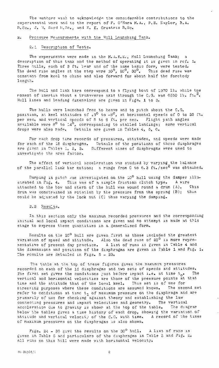
The experuwnts were made rn the M.A.E.E., Hull Launchng Tank; a descrlptlon of this tank and the method of operating It 1s given in ref. 1. Thee hulls, each of 3 ft. beair and of the same basic for", were tested. The dead rise angles at the step were lo', ZOO, 30'. This dead rise was constznt from keel to chine and also forward for about half the forebody length,
The hull and link bars correspond to a flying boat of 1370 lb. while tne moment of lnertla about a transverse axis ti-nough the C.G. was 6550 lb. fto2, Hull lines and leadug dimensions are given in Figs. 1 to 3.
The hulls were launched free to heave and to pitch about the C.G. pasltlon, at keel attitudes of +9O to -a', at horizontal speeds of 0 to 35 ft. per sec. and vertical speeds of 5 to 8 ft, per sec. Flight path angles available were 8' to 14', corresponding to stalled landings: some vert1ca1 drops were also made. !YJetalls are given in Tables 4, 5, ‘3.
For each drop time records of pressures, attitudes, and speeds were made for each of the 25 diaphragms. Details of the positions of these diaphragms are given Ii-l "n';les 1, 2, 3. Different sizes of diaphragms were used to lnvestlgate the area factor.
The effect of vertical acceleration was studied by varying the balance of the parallel link bar motion; a raxge from 0 to 6.3 ft./sec2 was obtained,
DampIng XI pitch ,&as uwestlgated on the 10' hdll using the damper lllu- strated ln Fig, 4. This was of a sunple frlctlon clutch type. A wire attached to the bow and stern of the hull was wound round a drum (A). This drum wds eonstralned in rotation by the pressure from the spring CB); this could be adJusted by the lock nut (C) thus varying the damplng.
2.2 T,esu1ts.
In this section only the "ax~mum recorded pressures and the corresponding uutlal and local Impact condltlons are given and no attempt ls made at this stag@ to express these quaotltles in a generalised form.
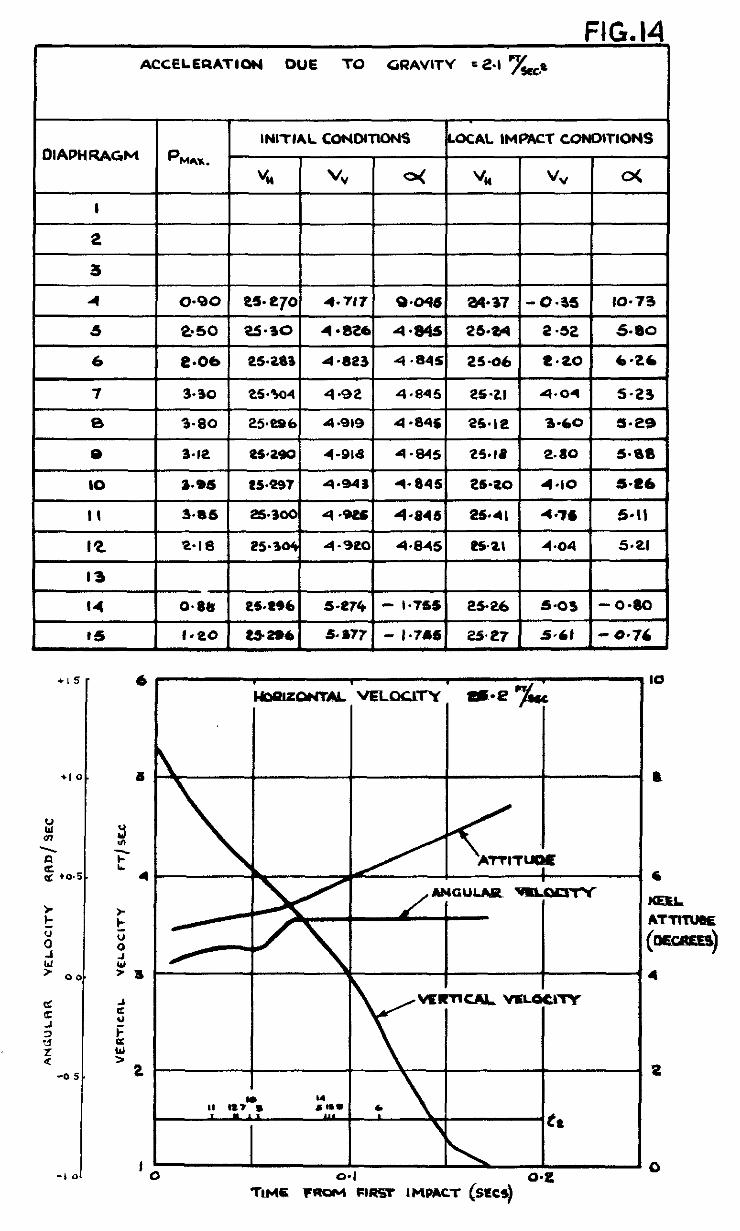
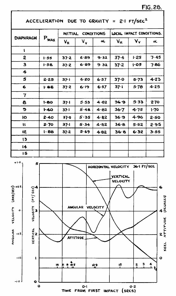
Results on the 2a" hull are given first as these included the greatest varlatlon of speed and attitude. Also the dead rise of 20' 1s "ore repre- sentatlve of present day practice. A lrst of runs 1s given in Table 4 and the dlmenslons and posItIon of the diaphragms are grven in Table 1 and Fzg. 1. The results are detailed in Figs. 5 - 23.
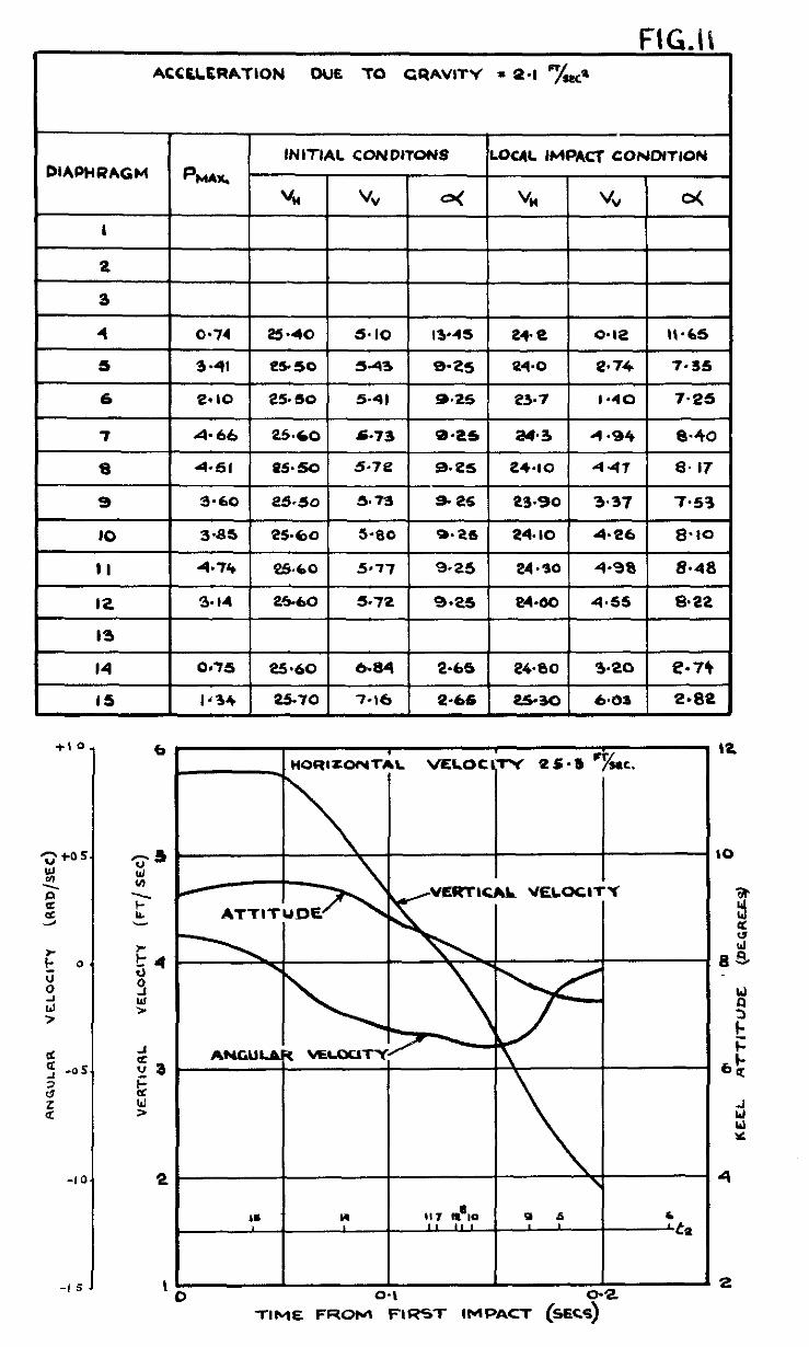
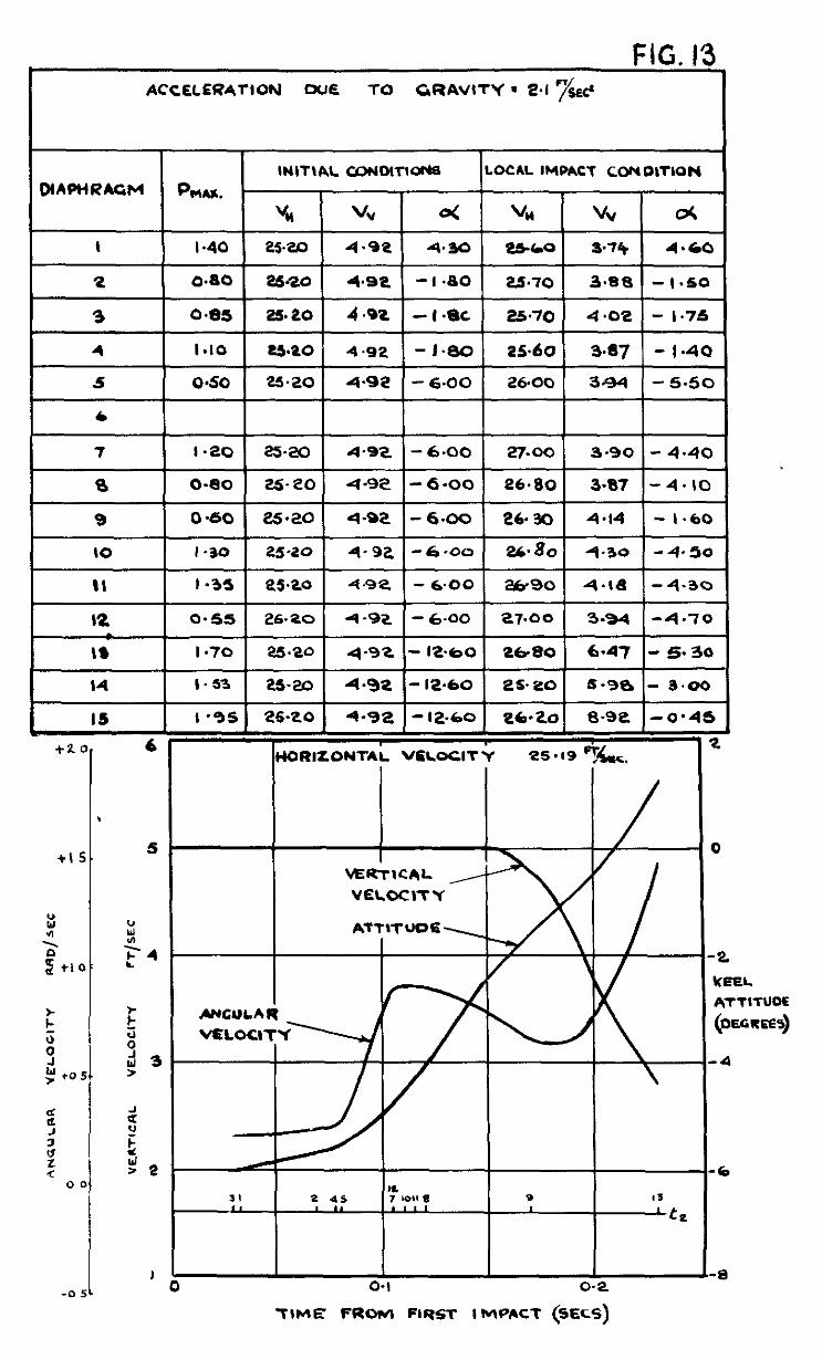
The table at the top of tnese figures grves the maxlmun pressures recorded on each of the 15 diaphragms and two sets of speeds and attitudes. The first set gives the condltlons ,,ust before impact 1.e. at time t,. The
vertical and horlzonta.1 velocltles are those of the pressure points at that trme and the attitude that of the local keelo This set IS of use for stressug purposes where these condltlons are assumed known. The second set refer to condltlons at time tl of maximum pressure on the draphrag" and are prunarlly of use for checkng against theory and establishing the law connecting pressures and impact velocrtles and geometry. The vertical acceleration dae to gravity 1s shown at the top of the table. The dlagrarr below the tables gives a time hlstory of each drop, showing the varratlon Of attitude and vertical velocltj of the C.G. with trme. A record of the times of nax~mu" pressures on the diaphragms 1s also shown.
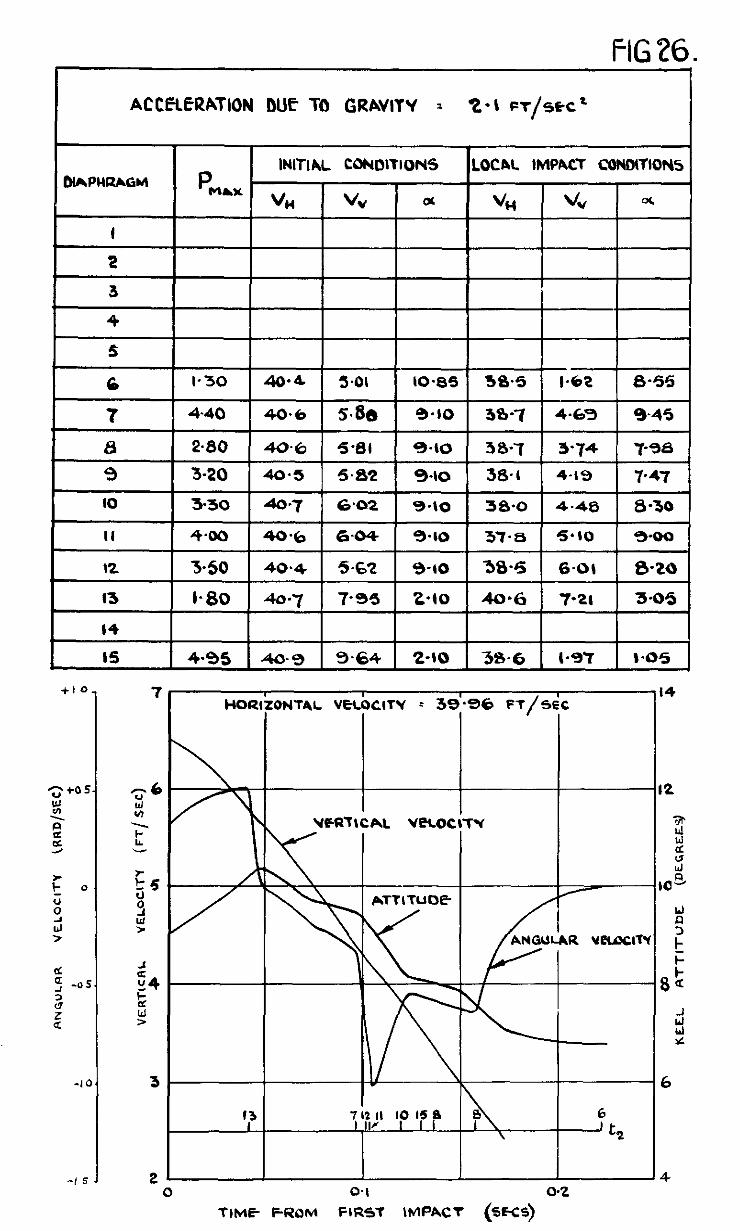
Flgse 24 - 36 give the results on the 30° hull. A list of runs 1s given in Table 5 and particulars of the diaphragms in Table 2 and Fig. 20 All runs on this hull were made with horizontal veioclty.
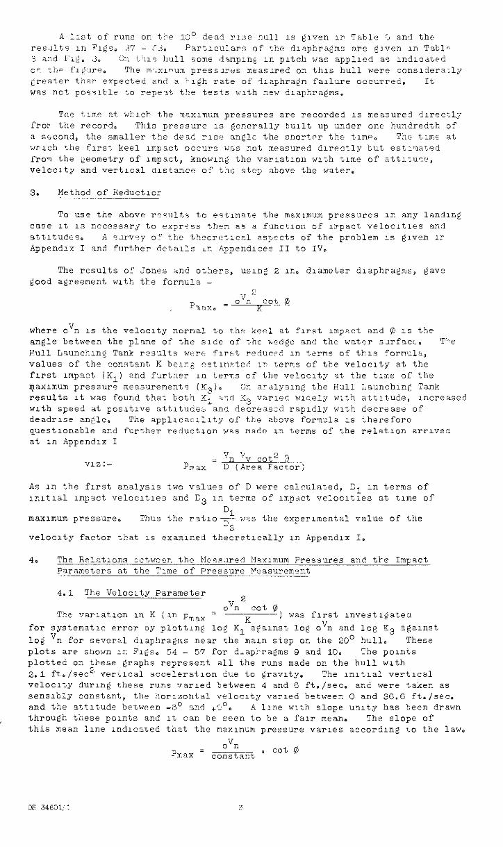
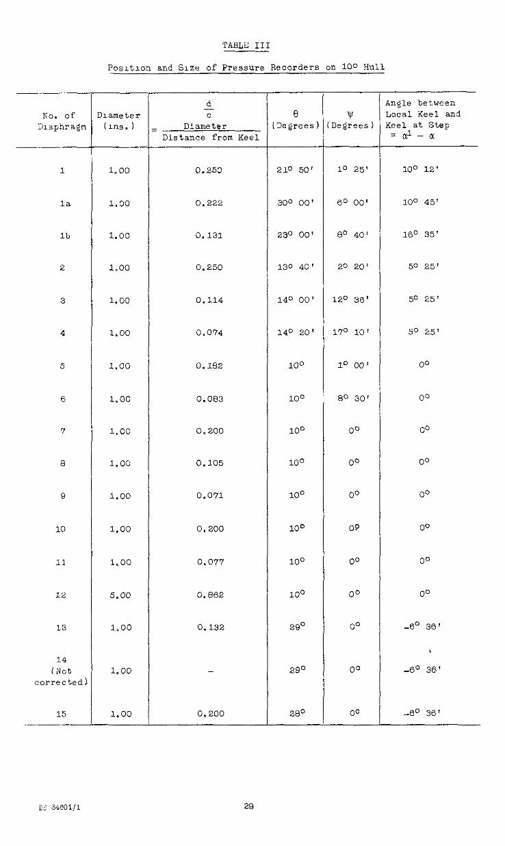
A 1;st of runs on t!le 1'30 dead rise null 1s given I> Table r, and the resJlts 1n Figs, 37 - Cd:, Fartlculars of rhe diaphragms are given in Tabl- 3 and Fig. 3. on t'l1s hull home dampIn& in pitch was applied as ndlcdted OT t.h- f1-:ure. The m>xlnum pressiras measxed on this hull were conslderacly treater thar expected and a klgh rate of Ilaphragn failure occurred. It was not poss1b1e to rq'e-it the tests with new diaphragms.
Tne tlmn at which the msxlmnum pressures are recorded 1s measured directl; fror the record. This pressure 1s generally built up under one hundredth of a second, the snaller the dead r~.se angle the snortpr the time. The tune at wrlch the first keel unpact occllrs was not measured directly tut estlxated from the geometry of Impact, knowing the varlatlon with time of attltuw, velocity and vertical alstance of the step above the water.
3. Method of Reductlor
To cse the above results to estlmaLe the mexlmum pressures in any landing case It 1s necessary to ex~r<ss then as a function of lrrpact velocltles and attltudts. A s.n-v-y ol? the thecretlcel aspects of the problem 1s given lr Appendlr I and further details in fippendlces II to IV,
The results of Jones and others, usng 2 in. diameter diaphragms, gave good agreement with the fornula -
where oVn 1s the velocity nornal to the keel at first rmpact and 0 1s the angle betwen the plane of the side of the >.cdge and the water snfaa. The Hull Launching Tank r?suits were first reducf-' m terms of this fornul6, values of the constant K berna estlriated in terms of the velocity at the first Impact (Ki) and furtner in terns of the velocity at the time of the qlaxmum pressure measurenents (I$). GE aralysn~ the Bull Launchlnc Tank results It was found that both K1 %nd K3 varied widely with attitude, Increased with speed at posltlve nttltudes and decreaszd rapidly with decrease of deadrlse ankle. The appllcacrllty of the above fornula 1s therefore questlonable and further reduction was nadc in tei-ms of the relation ari-lved at rn Appendix I
Y1Z:- = vn vv cot’) 3 PIP&X D (Area Factor)
As in the fu-st analysis two values of D were calculated, Sl in terms of w.ltl%l unpact velocltles and C 3 1n terns of lmpdct ve:oc1t1es at time of
D. maximum pressure, Thus the r%t1ofwis the experimental value of the
-3 veloczty factor that 1s examined theoretically in Appendix I.
4. The FLelatlons cetweex the Measxed Maxrmum Pressures and tke Inpact Parameters at the Time of Pressure Measurement
4.1 The Velocity Parameter
The varlatlon in K (in pr,ax = ovn
2 cot @
K ) was first rnvest1gateo
for systematic error oy plotting log K1 against log ovn and log K3 agarnst log 'n for several d1aphragrr.s near the main step on the 20' hull. These plots are shown in Figs, 54 - 57 for d,api-ragms 9 and 10. The points plotted on these graphs represent all the runs made on the hull with 2.1 ft./s& vert1ca1 acce1erat1on due to gravity, The lnltlal vertical velocity durng these runs varied between 4 and 6 ft,/sec. and were taken as sens1b1y constant, the horizontal velocity varied between 0 and 36.6 ft./set. and the attitude between -8' and +C'. A line with slope unity has been drawn through these points and It can be seen to be a fair mean. The slope of this mean line Indicated that the maxunum pressure varies according to the law.
ovn pmax = constaKi o cot rg
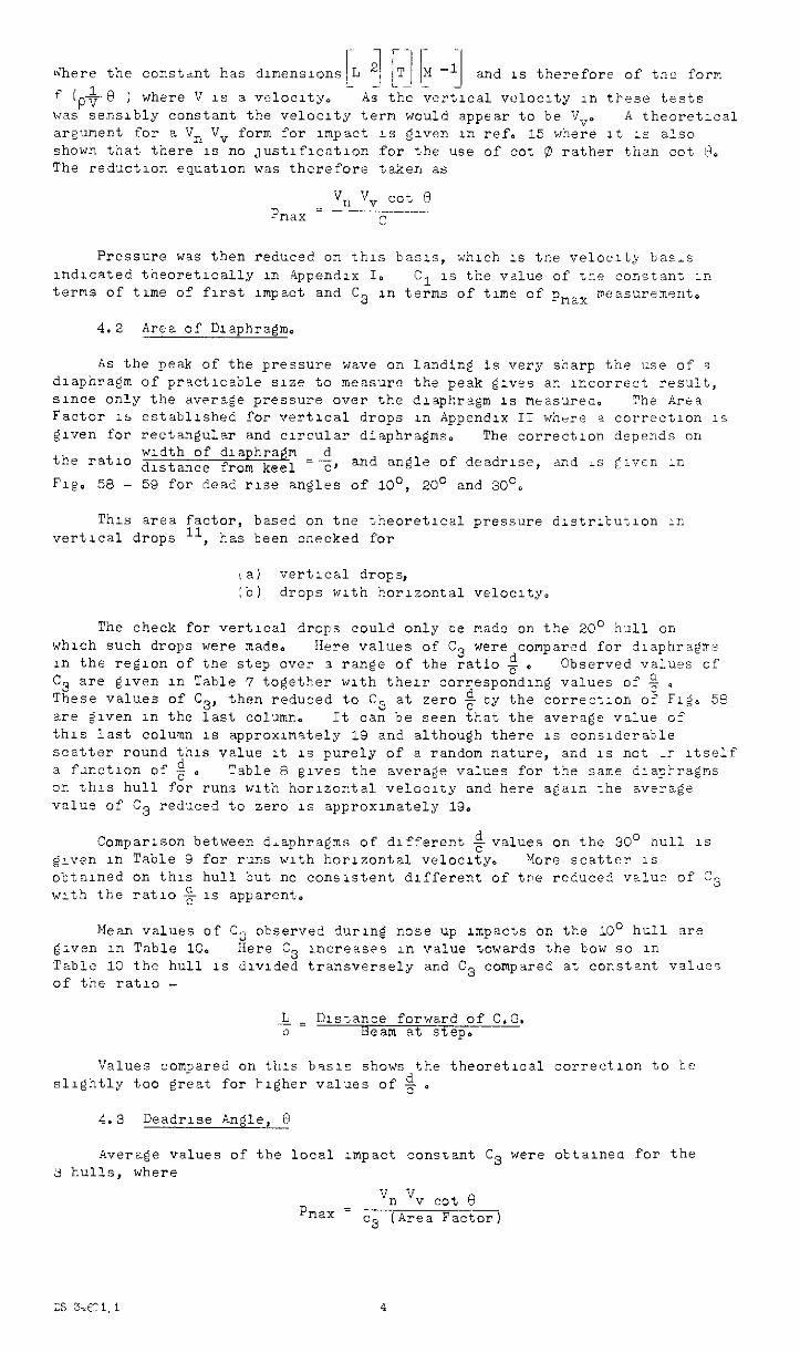
ir'here the constant has dilmenslons L I_ ][$-q and 1s therefore of tne form
f i&8 ) where V 1s a velocity, As the vertical vcloclty in these tests was sensibly constant the velocity tern would appear to be fJvo A theoretIca argument for a Vn Vv form for unpact 1s given ln ref, 15 where It 1s also shown that there IS no justlflcatlon for the use of cot 0 rather thsn cot 6, The reduction equation was therefore taken as
vu v, cot e Pnax = - - c
Pressure was then reduced on this basis, which 1s tne velocity bas,s lndlcated theoretrcally in Appendix I. Cl 1s the value of ste c03*tan: -n terns of tune of first impact and C3 in terms of time of pmax weasurem?nt.
4.2 Area of Dlaphraem,
As the peak of the pressure wave on landing is very sharp the use of i diaphragm of-practicable size to measure the peak gives ar. xcorrect result, since only the average pressure over the dlaphrapm 1s neasurec, "he Area Factor 1s established for vertical drops in Appendix II where a correctlon 1s given for rectangular and circular diaphragms. The correction depends on
width of dla hra II d the ratlo distance fro; k&l =c, and angle of deadrlse, and LS clvcn LII
F1g. 58 - 53 for dead rise angles of lo', 20' and 30'0
This area ;Tctor, based on tne theoretical pressure dlstrlbutlon in vertical drops , has been cneckrd for
: a) vertical drops, :b) drops with horizontal velocity.
The check for vertical drops could only ce made on the 20' hull on which such drops were made, Here values of c3 were compared for dlaphra@rs III the region of tne step over 3. range of the ratio $ o Observed values of C3 are given in Table 7 together with their correspondu,g values of + a These values of C3, then reduced to C3 at zero $ oy the correct:on o: Fig, 53 are given III the last column. It can be seen that the average value o? this last colunn 1s approxlmstely 13 and although there 1s considerable scatter round this value rt 1s purely of a random nature, and 1s not -r Itself a fxct1on of g o Table 8 elves the average vaiues for the same dlap5ragms or, &hls hull for runs with horizontal velocity and here @au the av?rage value of C3 reduced to zero IS approxunately 13,
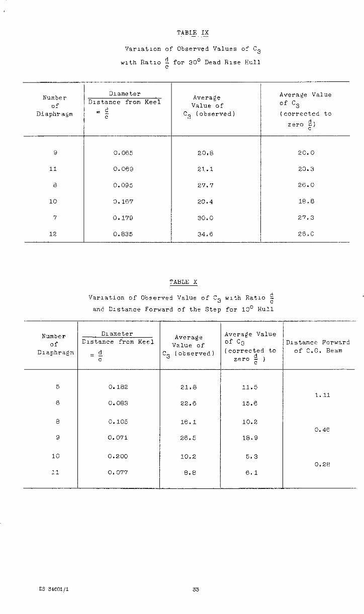
Comparrson between diaphragms of different $values on the 30' null 1s elven III Table 9 for runs with horizontal velocrty. %re scatter 1s obtalnod on this hull but no consistent different of tge reduce3 value of C3 with the ratlo + 1s apparent.
Mean values of C3 observed during nose Up impacts on the 10' hull are given ~n Table 10, Here C3 increases in value towards the bow so in Table 10 the hull 1s dlvlded transversely and C3 conpsred at constant vilties of the ratlo -
_ = Distance forward of C.O. L 3 Beam at step.
Values compared on thzs b=asls shows the theoretical correctlon to be slightly too @eat for i-lgher values of $ a
4.3 Deadrlse Angle, 0
Average values of the local Impact constant C3 were o'ctalnea for the 3 hulls, where
VII P
vv cd 6 nax = c3 (Area Factor)
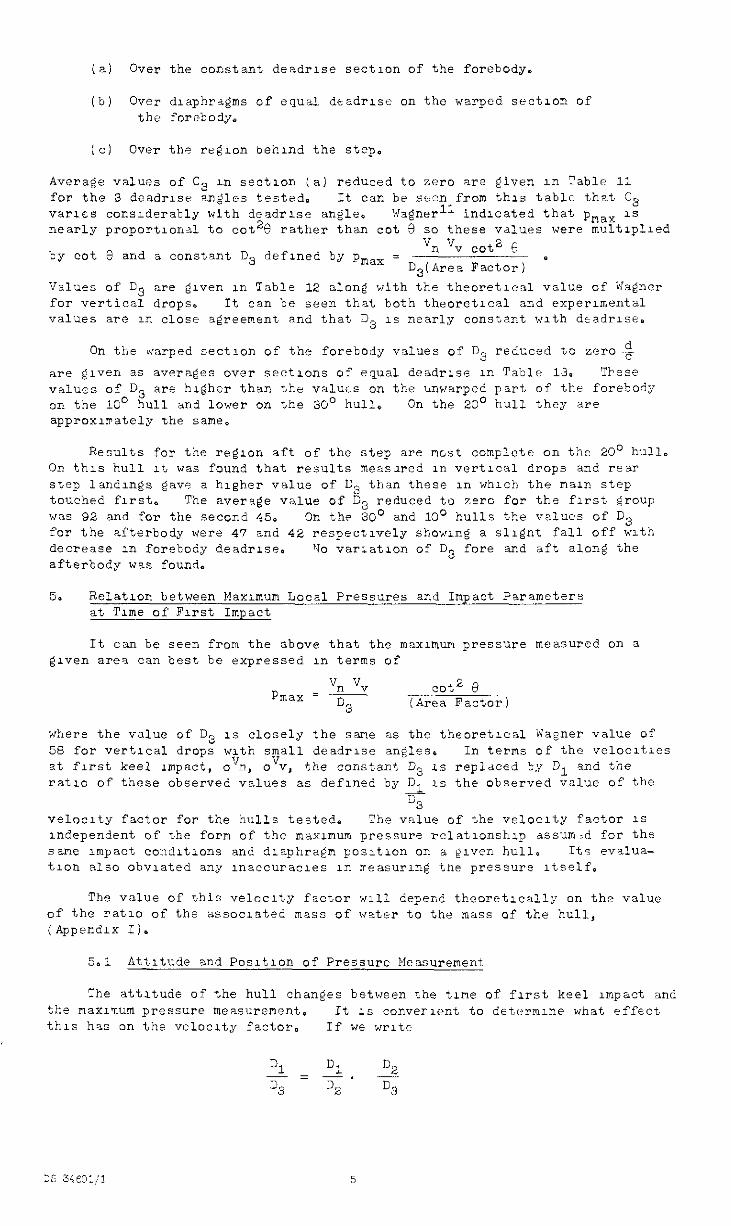
(a) Over the constant deadrlse section of the forebody.
(b) Over dlaphrdgms of equal deadrise on the warped section of the forebody,
[c) Over the rcglon behind ths step.
Average values of C3 11, section (a) reduced to zero are given ln Fable 11 for the 3 deadrlse angles tested. It can be seen from this table that C3 var1c.s considerably with deadrlse angle, Wagnerll indicated that pmax 1s nearly proportIona to cot28 rather than cot E! so these values were mcltiplled
by cot 8 and a constant D3 defined by pmax = vn vv cot2 F _I
D D3ikrea Factor)
Values of D3 are elven in Table 12 along with the theoretical valw of Wa@xer for vertical drops. It can be seen that both theoretlcal and experuental values are in close agreement and that D3 1s nearly consbant with dtadrlse.
On the &xi-ped sectlon of the forebody values of 03 redGced to zero+
are given as averages over sections of equal deadrlse 1~. Table 13. Tbf?SfZ values of D3 are hldher than the valuts on the uwarped part of the forebody on the 10' hull and lower on the 30' hull, On the 20' hull they are approxurately the same.
Results for the reelon aft of the step are nest complete on the 20' hull. On this hull At, was found that results measilred III vertical drops and rear step landu-&s gave a higher value of D3 than these in whrch the main step touched first. The average value of C3 reduced tu zero for the first group was 92 and for the second 45. On the 30' and 10' hulls the values of D3 for the afterbody were 47 and 42 respectively showing a sllgnt fall off with decrease 1n forebody deadrlse. '40 var;atlon of D3 fore and aft along the afterbody was found.
5. Relation between Maxunum Local Pressures and Impact Parameters at Tune of First Impact
It can be seen from the above that the maxunum pressure measured on a given are? can best be expressed in terms of
P Vn Vv
max = ~ cot2 0
% (Area Factor)
where the value of D3 1s closely the sane as the theoretical Wagner value of 58 for vertical drops with small deadrlse angles, In terms of the velocltles at first keel Impact, oxJn, o'v, the constant D3 1s repldced by D1 and the ratio of these observed values as defined by% 1s the observed value of the
c3 vnloclty factor for the hulls tested. The value of the velocity factor 1s Independent of the form of the maxunum pressure relatlonshlp assumzd for the sane Impact conditions and diaphragm posltlon on a given hull, Its eva1ua- tlon also obviated any lnaccuracles in rreasur& the press'xe Itself.
The value of this velocity factor ~111 depend theoretically on the value of the ratlo of the associated mass of water to the mass of the hull, (Appendix Il.
5.1 Attitude and Posltlon of Pressure Measurement
Yhe attitude of the hull changes between the tine of first keel impact and the max1llum pressure measurement. It 1s convex-lent to determine what effect this his on the velocity factor. If we write
31 Dl - = -. 2 % D2 03
35 34f01il 5
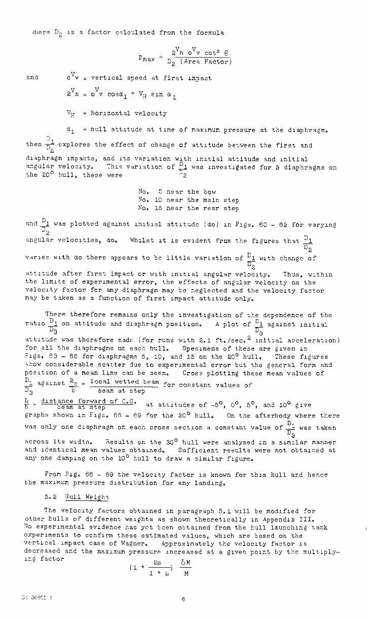
dlere D2 1s a factor calculated from the formula
Fmax = 2Vl.l ovv cot2 e
D2 (Area Factor)
and o'Jy = vertical speed at first Impact
zvn = ovv COStil + vg s1n u1
a1 = hull attitude at tune of maxunum pressure at the diaphragm.
Dl thenr explores the effect of change of attrtude between the first and 2
diaphragm unpacts, and Its varlatlon with uutial attitude and nitial angular ve1oc1ty. This varlatlon of 3 was lnvestlgated for 3 diaphragms on the 20' hull, these were d2
No. 5 near the bow No. 10 near the main step x0. 15 near the rear step
and 1 was plotted against lnltlal attitude iclo) in Figs.
% 60 - 62 for varying
angular velocities, ao. Whilst It 1% evident from the figures that 1 %
vnrles with clo there appears to be little variation of D1 with change of 5
attitude after first impact or with lnltlal angular velocity. Thus, wlthzn the llmlts of experImenta error, the effects of angular velocity on the velocity factor for any diaphragm may be neglected and the velocity factor nay be taken as a function of first unpact attitude only.
There therefore remains only the Investigation of the dependence of the rat10 D 1 on attitude and diaphragm position.
% A plot of 01 against lnltlal
% attitude was therefore made (for runs wth 2.1 ft./seca2 lnitlal acceleration) lor all the diaphragms on each hull. Specunens of these are given in Rigs. e3 - 65 for diaphragms 5, 10, and 15 on the 20' hull, These figures show considerable scatter due to experimental error but the general form and posltzon of a mean lone can be seeno Cross plotting these mean values of
+= distance forward of. beam at step at attitudes of -5O, O', 5', and 10' give
graphs shown in Figs. 66 - 69 for the 20' hull. On the afterbody where there
was only one diaphragm on each cross sectlon a constant value of- was taken %
D3 across its wldtn, ;lesults on the 30' hull were analysed 1n a slmllar manner and ldentlcal mesn values obtaned. Sufflclent results were not obtained at any one damping on the 10' hull to draw a similar figure.
From Fig. 66 - 69 the velocity factor 1s known for this hull and hence the maximum pressure dlstrlbution for any landng.
5.2 Hull Weight
The velocity factors obtained in paragraph 5.1 ~111 be modlfled for other hulls of different weights as shown theoretlcally in Appendix III. No experimental evidence has yet been obtalned from the hull launching tank experiments to confIrm these estimated values, which are based on the vert1ca1 unpact case of Wagner. Approximately the velocxty factor IS decreased and the maximum pressure increased at a given point by the multlply- 1ng factor
(1 +2!!+ M l+U M
I?
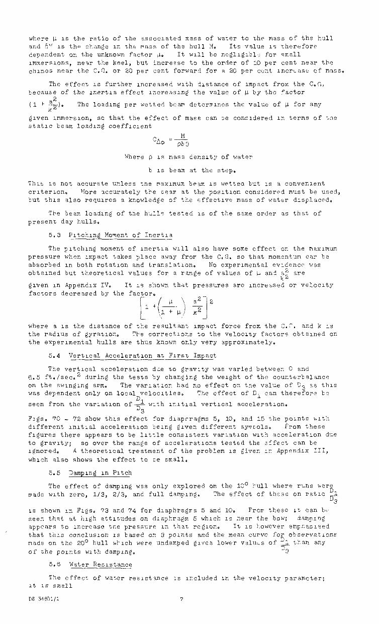
where 1; 1s the ratio of the associated mass of water to the mass of the hull and 5"" 1s th<A change II-, tht pass of the hull M. Its value IS Therefore dependent on the unknown factor @e It will be negllg~bli for small ImmersLons, new the keel, but increase to the order of 10 per cent near the chines near the C.G. or 20 per cent forward for a 20 per cent ~ncriasi- of p13sS.
The effect IS further Increased with 3lstance of Impact from the C,C, because of the lnert~a effect u~creeslng the value of fi by the factor
(1 1 ;;I* The loadlnc per wetted bear deterlnlnes the value of v for any
given lmmrrslon, so that the effect of mass can 3e conzldered in terms of tne static beam losdlng coeffrclent
M "a0 =- pb3
Where p IS mass densrty of water
b 1s beam at the step.
This 1s not accurate u-less the maximum beam 1s wpttea but LS a convenient criterion. Yore 3ccurate1y t're cearr at the posltlon cons:dered must be used, but this also requulres a knowledge of the effectiw mass of watrr dlsplacr-d.
The beam loadrng of tne hldlls tested 1s of the same order as that of presen-c day hulls.
5.3 Fltchlng Mownt cf Inertia
The pltchug moment of rnertla ~111 also have some effect on the maximum pressure when impact takes place away frorr the C,G. so that momentum ca? be absorbed ln both rotation and translation. No experimental evldencc was obtalned but theoretlcal values for a rang!? of values of Ll an? i2 are
k2 given in Appendix IV. It LS shown that pressures are increased or velocity factors decreased by the factor.
p + (;$ $-I 2 -
where a 1s the distance of the resultant Impact force from the C.C. and k 1s the radius of gyration. 3e corrfctlons to the velocity factors obtained on the experlmental hulls are thus know. only very approximately.
5.4 Vertical Acceleration a'~ Flrs~ Impact
The vertical acceleration dfie to gravity was varied between 0 and 6.5 ft./sec.2 during the tests by changing the weight of the counterbalance on the swlnglng arms The varlatzon had no effect on tne value of D3 as this was dependent only on local velocities.
Dl The effect of Di can therefore 'be
seen from the varlatlon of- with lrltlal vertical acceleration. D3
FlgS. 70 - 72 show this effect for dlaprragms 5, 10, and 15 the points blth different lnltlal acceleration belrg given different sy~~cols~ From these figures there appears to be little consistent variitlon with acceleration due to gravrty; so over the range of acceleratrons tested the Effect can be Ignored. A theoretical treatment of the problem 1s civen III Appendix III, which also shows the effect to ze small.
5.5 Damplre XI Pitch
The effect of damping was only explored on the 13' bull where rlilis kere vade with zero, l/3, Z/3, and full damping. The effect of these on ratlc 51
% LS shown in Figs. 73 and 74 for dlaphragrrs 5 and 10. Frorr these It can b- seen that at high attitudes on dzaphragm 5 which :s near the bow: damplng appears to increase tne pressure ln that regror. It 1s however empnaslsed that this conclusion IS based on 3 paints and the mean curve for observations made on the 20' hull htlch were undamped gives lower values of LA th3i7 any
of the FOliZtS with damping. CL'
5.6 water Resistance
The effect of water resistance 1s Included x-, the velocity parameter; 1t 1s small
DS 54m:/1 7
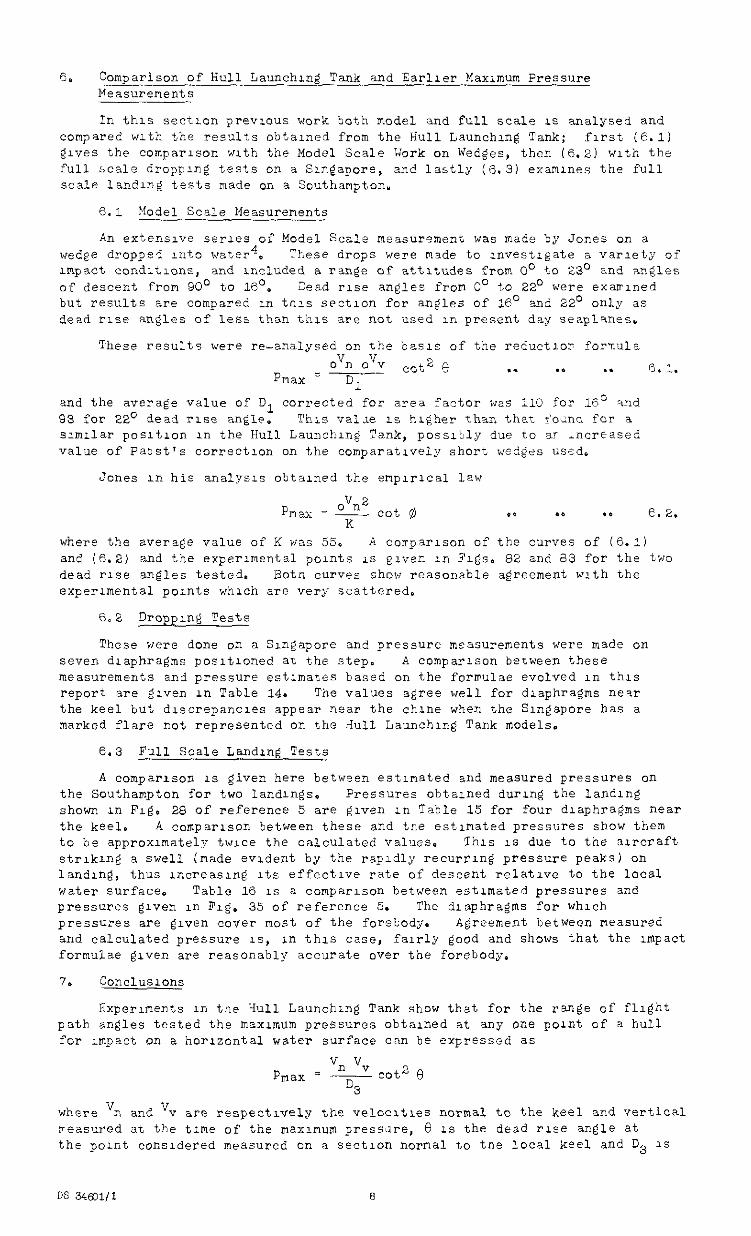
6. Comparison of Hull Launching Tank and Earlier Maximum Pressure Measurenents
In this section previous work both model and full scale 1s analysed and compared with the res,Jlts obtained from the Hull Launching Tank; first (e.1) elves the comparison with the Model Scale Work on Wedges, thcr. (6.2) with the full scale dropping tests on a Sln~apore, and lastly (6.31 examines the full scale landlni tests made on a Southampton.
6.1 Model Scale Measurements
An extensive serves of Model Scale measurement was made by Jones on a wedge dropped ~cto water', These drops were made to xwestigate a variety of rmpact condltlons, and included a ran@ of attitudes from 0' to 23' and angles of descent from 90' to 16's Dead rise angles from Co to 22' were exarrlned but results are compared ln tnls section for aneles of 16' and 22' only as dead rise angles of less than this are not used 11, present day seaplanes.
These results were x-analysed on the basis of the reductlor formula ovn ovv
Pnax =-T-- cot 2 8 . . .* . . 6.1.
1 and the average value of D, corrected for area factor was 110 for 16' and 93 for 22' dead rise an$lp. This valx 1s hleher than that r'o~nc for a sunllar posltlon in the Hull Launchrng Tank , possltly due to BT Ancreased value of Paast's correctIon on the comparatively short wedges used,
Jones in his analysis obtauied the enplrleal law
where the average value of K was 55. A corrparlson of the curves of (6.1) and (6.2) and the experimental pwnts 1s giver. in Figs, 82 and a3 for the two dead rise angles tested. Botn curves show reasonable agreement with the experimental points which are very scattered.
These were done on a SuQapore and pressure measurements were made on seven dlaphraems posltloned a~ the step. A comparison beLween these measurements and pressure estunates based on the fornulae evolved ln this report are e~ven in Table 14. The values agree well for diaphragms near the keel but dkscrepancles appear near the chine when the Singapore has a marked flare not represented on the riull Launching Tank models.
6.3 Full Scale Landlne Tests
A comparison 1s given here between estimated and measured pressures on the Southampton for two landings. Pressures obtained durlng the landing shown in Fig. 28 of reference 5 are crven in Table 15 for four diaphragms near the keel. A comparison between these and tne estimated pressures show them to be approximately twice the calculated values. This 1s due to the arcraft otrlkrng a swell (made evident by the rapidly recurring pressure peaks) on landrng, thus uxreasug Its effective rate of descent relative to the local water surface. Table 16 LS a comparison between estimated pressures and pressures given in Fxg. 35 of reference 5. The diaphragms for which pressures are given cover most of the forebodyo Agreement between measured and calculated pressure is, in this case, fairly good and shows that the uopact formulae @ven are reasonably accurate over the forebody.
7. COnClUSlOnS
Experunents in tne Hull Launching Tank show that for the range of flliht path angles tested the maximum pressures obtained at any one point of a hull for Impact on a horizontal water surface can be expressed as
where v n and 'v are respectxvely the velocxtles normal to the keel and vertical xeasured at the time of the maximum pressare, 8 1s the dead rise angle at the pornt consldered measured on a sectron normal to tne local keel and D3 1s
DS 34601/l 8
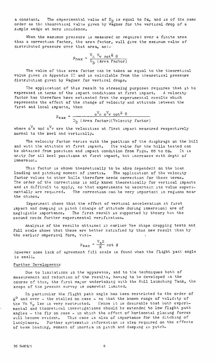
a constant. The experimental value of D3 1s equal to 54, and 1s of the .same order as the theoretical value given by Wagner for the vertical drop of a simple wedge at zero uxldence.
When the maximum pressure 1s measured or requred over a flnlte area than a correction factor, the area factor, ~111 give the maxunum value of dlstrlbuted pressure over that area, as:-
P - v, vv cot2 0 max - D3 (Area Factor)
The value of this area factor carz be taken as equal to the theoretlcal value given in Appendix II and IS calculable from the theoretical Pressure distrrbutlon given by Wagner for vertical drops.
The appllcatlon of this result to stressing purposes requires that It be expressed III terms of the impact condltlons at first unpact. A ve1oc1ty factor has therefore been estimated from the experunental results which represents the effect of the change of velocity and attitude between the first and local xnpacts, then
Pmax = ovn ovv cot2 6
D3 (Area factor)(Veloclty factor)
where ovn and OVV are the velocities at first unpact measured respectively normal to the keel and vertically.
The velocity factor varies with the position of the diaphragm on the hull and with the attitude at first impact. Its value for the hulls tested can be obtained from posltlon and impact condition from Figs. 66 to 69. It 1.3 unity for all keel positrons at first unpact, but increases w1t.h depth of immersx3n.
This factor IS shown theoretically to be also dependent on the beam loading and pltchng moment of uertla. The appllcatux, of the velocity factor values to other hulls therefore needs correction for these terns. The order of the correetlons 1s only known theoretlcally for vertlczl impacts and 1s difficult to apply, so that experiments to ascertaln Its value experl- mentally are requred. The correction can be very important III regions near the chuxs.
Experiment shows that the effect of vertical acceleration at first impact and dampIng in pitch (change of attitude during ~mmerslon) are of negligible importance. The first result IS supported by theory bur. the second needs further experimental verification.
Analysis of the results obtalned III earlier Vee shape dropping tests and full scale shows That these are better satufled by thrs new result than by the earlier emperlcal form, viz:-
PiTlaX v,2
K co' a However some lack of agreement full scale 1s found when the fLight path angle is small.
Further Developments
Due to lunltatlons in the apparatus, and to the techniques both of measurement and reduction of the results, having to be developed in the course 05 this, the first ma,~or undertaking with the Hull Launching Tank, the scope of the present survey 1s somewhat llmlted.
In particular the flrght path angle has been restricted to the order of 8' and over - the stalled on case - so that the known range of validity of the Vn V law 1s very rzstrlcted. Hence It 1s desirable that both experi- mental a;d thearetlcal nvestrgatlons should be extended to low flrght path angles - the fly on case - in which the effect of horizontal plar.lng forces ~111 become evident. This case 1s also of unportance for the dltchlng of landplanes. Further systematic lnformatlon 1s also requred on the effects of beam loading, rPoment of lnertla in Pitch and damplng in pitch,
DS 34601/l 9
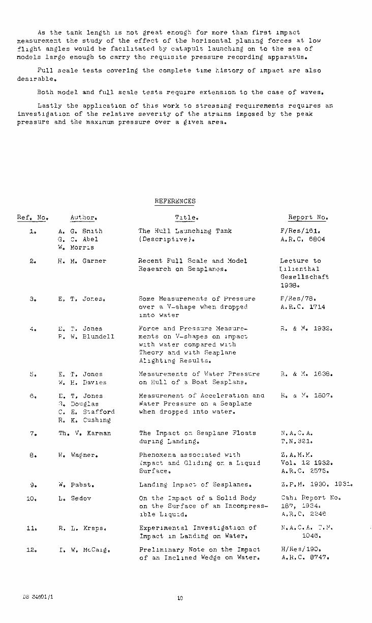
As the tank length 1s not great enough for mope than first unpact measurement the study of the effect of the horizontal planing forces at low flight angles would be facllltated by catapult launching on to the sea of models large enough to carry the requlslte pressure recording apparatus.
Full scale tests covering the complete trme history of impact are also deslrable.
30th model and full scale tests requu-e extension to the case of waves.
Lastly the appllcatlon of this work to stressing requrrements requxes an investlgatlon of the relative severity of the strains imposed by the peak pressure and the maximum pressure ova- a grven area.
Ref. No. Author.
1.
2.
3.
4.
5.
6.
7.
e.
9.
10.
11.
12,
A. G. Smith G. C. Abel W. Morris
H. M. Garner
E, T, Jones.
E. T. JOilC!.?
F. W. Elundell
E. T. Jones ‘+I. e. DaVleS
E. T. Jones G. Douglas c. E. Stafford R. K. C'whlng
Th. V. Karman
H. Wagner.
W. Pabst.
L. Sedov
R. L. Kreps.
I. W. McCalg,
REFERENCES
Tztle.
The Hull Launching Tank IDescr1pt1ve).
Recent Full Scale and Model Research on Seaplanes.
Some Measurements of Pressure over a V-shape when dropped into water
Force and Pressure Measure- ments on V-shapes on unpact with water compared with Theory and with Seaplane Alrghtug Results.
Measurements of Water pressure on Hull of a Boat Seaplane.
Measurement of Acceleration ana Nater pressure on a Seaplane when dropped Into water.
The Impact on Seaplane Floats during Landing.
Phenomena associated with impact and Glldlng on a Lrquld Surface,
Landing Impact of Seaplanes.
On the ;mpact of a Solid Body on the Surface of an Incompress- lble Llquld.
ExperImental Investlgatlon of Impact in Landing on Water.
Prellmlnary Note on the Impact of an Inclined Wedge on Water.
ReFOi-t No.
F/Res/lGl. A.R.C. 6804
Lecture to Llllenthal Gesellschaft 1938.
F/Res/7S. A.R.C. 1714
2.. & Mn, 1932.
N.A.C.A. T.N. 321.
Z.A.M.M. Vol. 12 1932. A.R.C. 2575.
Z.F.M. 1930. is310
Cahl Report No. 187, 1334* A.R.C. 2246
N.A.C.A. T.P. 1046.
H/Res/lSO. A.R.C. 8747.
2s z&Q?/1 10
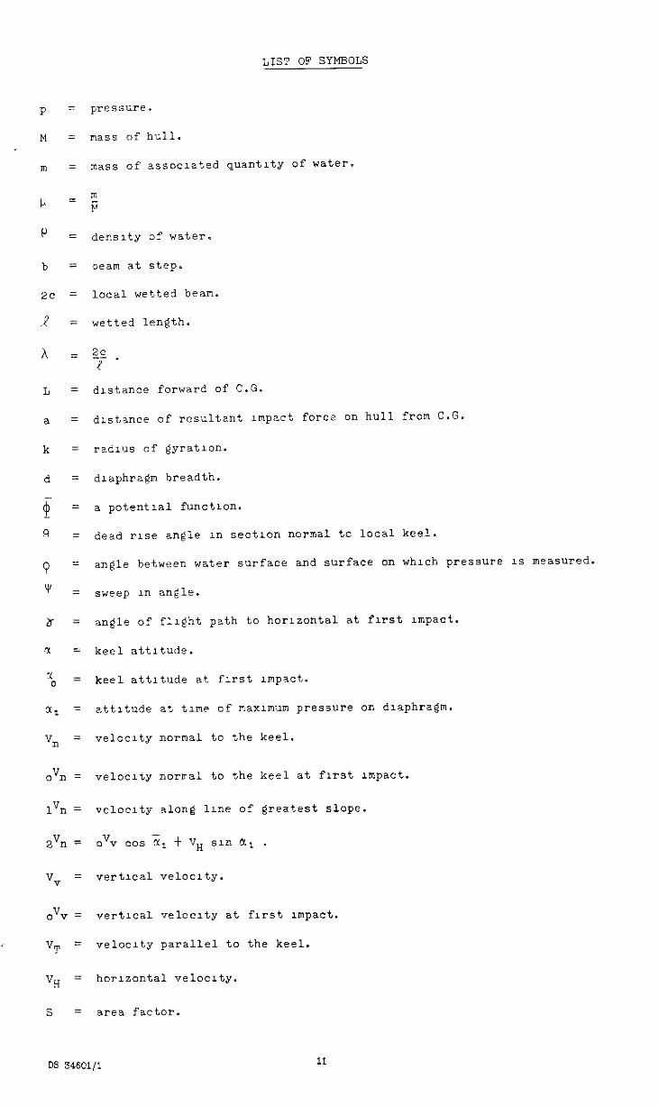
LIST OF SYMBOLS
P = pmssure.
M = mass of hull.
m = mass of associated quantity of water.
I-I =;
P z density of water.
b = beam at step.
2c = local wetted beam.
z? = wetted length.
h = z_c ! .
L = distance forward of C.G.
a = drstance of resultant Impact force on hull from C.G.
k z radius of gyration.
d = diaphragm breadth.
$ = a potent1a1 function.
Q = dead rise angle 1n section normal to local keel.
Q = angle between water surface and surface on which pressure 1s measured.
'v = sweep In angle.
b = angle of flight path to horizontal at first impact.
CL = keel attitude.
I 0 = keel attitude at first mpact.
%(1 = attitude at time of naxlmum pressure on diaphragm.
v, = velocity normal to the keel.
."I3 = velocity noriral to the keel at first rmpact.
l", = ve1oc1ty along 11ne of greatest slope.
2”iY = ovv cos & t VH sln LYl .
Vv = vert1ca1 ve1oc1ty.
ov-? = vert1c.31 ve1oc1ty at first mpact.
"T = velocity parallel to the keel.
V H = horizontal velocity.
s = area factor.
DS S46c!l/l I1
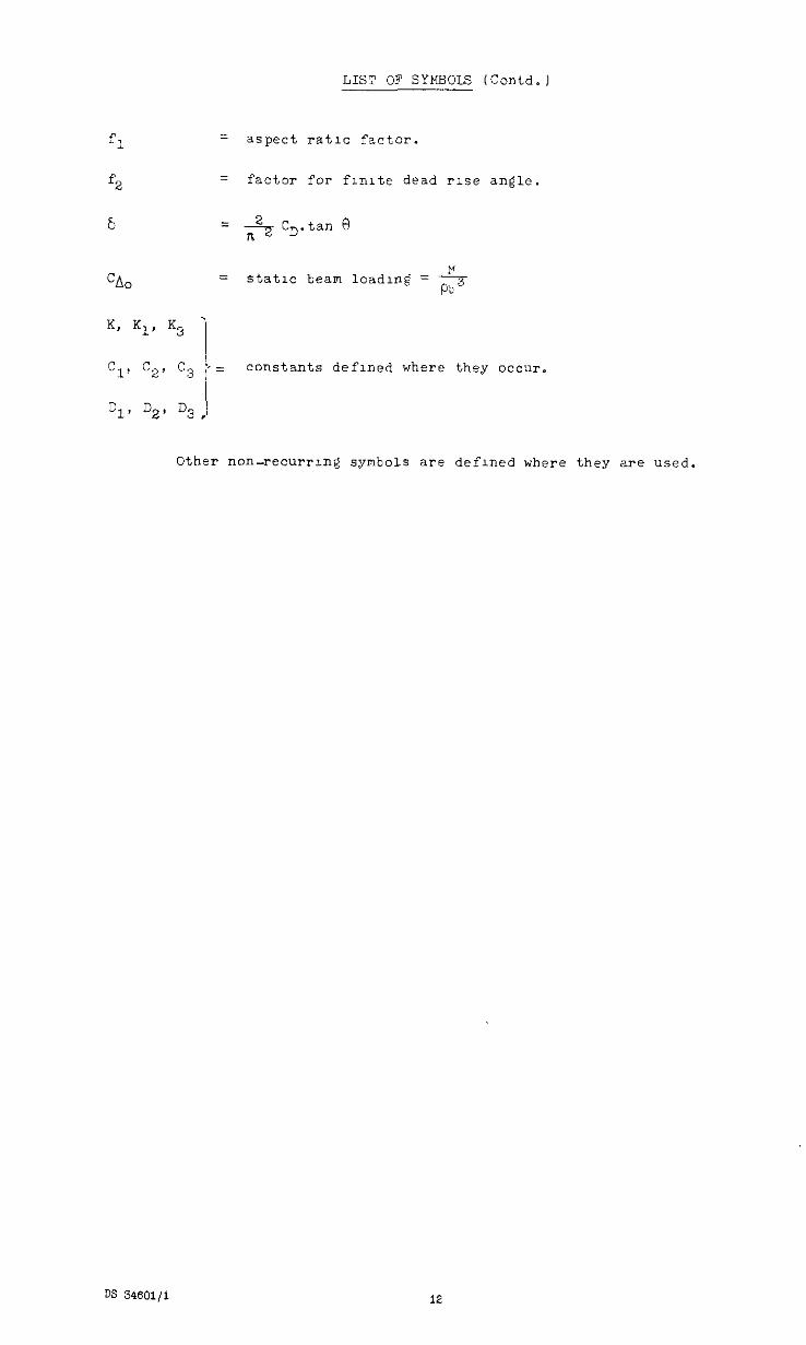
LIST OF SYMBOLS (Contd.)
fl = aspect rat10 factor.
f2 = factor for flmte dead rise angle.
6 = ;;ZZc,.tanF)
zz Static beam loadmg = 2- pa 3
c 1' C29 C3 !, _
I-
constants defmed where they occur.
Other non-recurrmg symbols are defined where they are used.
DS 34601/l 12
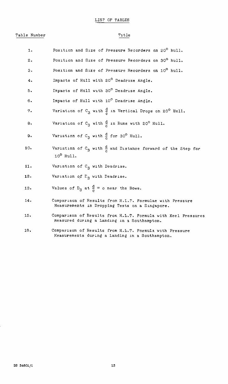
LIST OF TABLES
Table Number Title
1.
2.
3.
4.
5.
6.
7.
8.
9.
10.
Positron and Size of Pressure Recorders on 20' hull.
Posrtlon and Srze of Pressure Recorders on 30' hull.
Posltlon and Sue of Pressure Recorders on loo hull.
Impacts of Hull with 20' Deadrlse Angle.
Impacts of Hull with 30' Deadrlse Angle.
Impacts of Hull with 10" Deadrlse Angle.
Variation of C3 with $ in Vertical Drops on 20° HUll.
Var1atron of c3 with z in Runs with 20' Hull.
variation of c3 with ; for 30' Hull.
Varlatlon of c3 with $ and Distance forward of the Step for
10' Hull.
11.
12.
13.
14.
Varlatlon of C3 with DeadrIse.
Varlatron of r3 with Deadrlse.
Values of D3 at g = o near the Bows.
Comparison of Results from H.L.T. Formulae with Pressure Measurements in Dropping Tests on a Singapore.
15.
16.
Comparison of Results from H.L.?. Formula with Keel Pressures measured during a Landing in a Southampton.
Comparison of Results from H.L.T. Formula with Pressure Measurements during a Landin? in a Southampton.
FIGURZ NUMBER
1
2
3
4
5 - 23
24 - 36
37 - 53
54
55
56
57
58
59
60
61
62
63
64
65
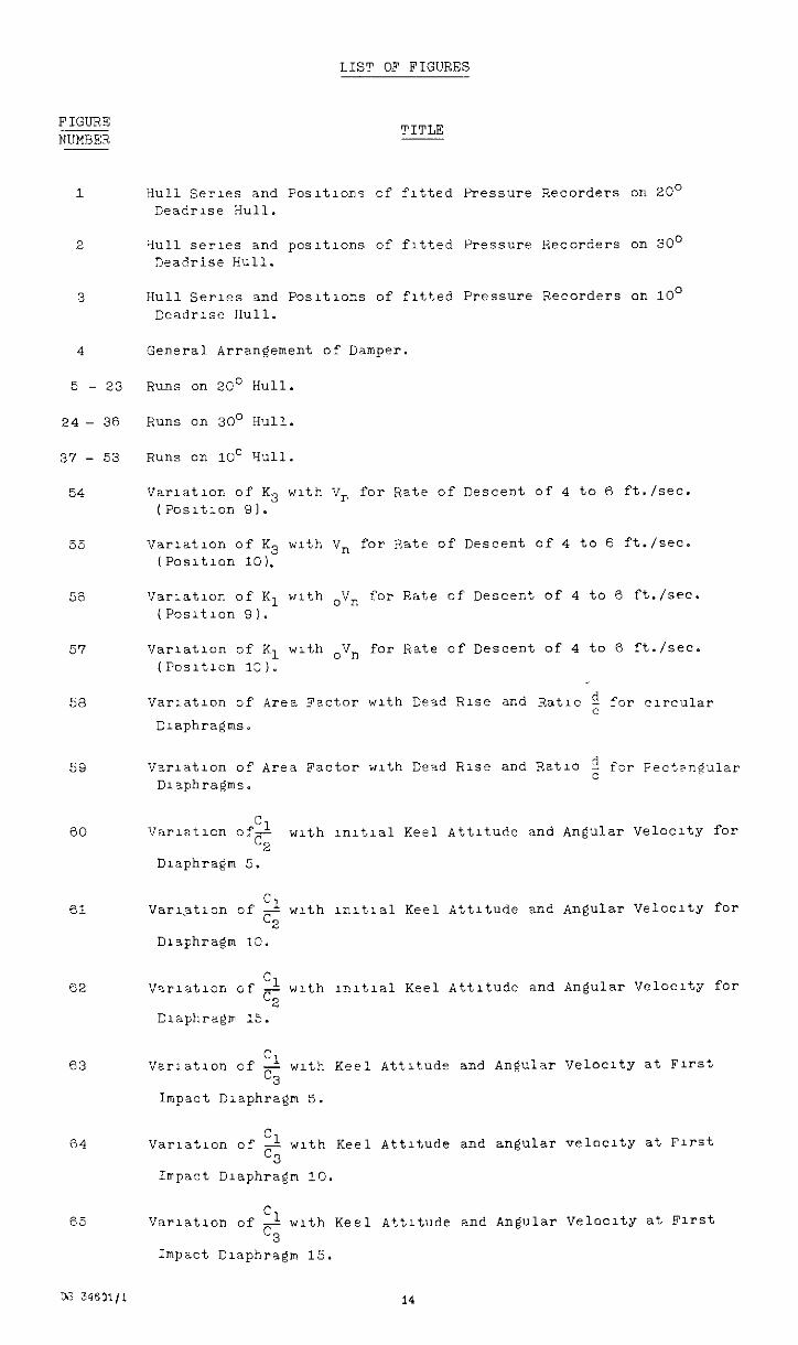
LIST OF FIGURES
TITLE
Hull Serres and Fosltlons of fltted Pressure Recorders on 20° Deadrise Hull.
3~11 series and pasltlons of fitted Pressure Recorders on 30' Deadrise Hull.
Hull Series and Posltlons of fitted Pressure Recorders on loo Ceadrlse Hull.
General Arrangement of Damper.
Runs on 20' Hull.
Runs on 30' Hull.
Runs on 10' Yull.
Varlatlon of K3 with V, for Rate of Descent of 4 to 6 ft./seC. (Posltlon 91.
Varlatlon of K3 with V, for Rate of Descent of 4 to 6 ft./set. (Posltlon 10).
Varlatlon of Kl with .V, for Rate of Descent of 4 to 6 ft./SW. (Posltlon 91.
Varlatlon of Kl with oV, for Rate of Descent of 4 to 6 ft./seC. (Posltlon lO,).
Varlatlon of Area Factor with Dead Rise and Ratlc ; for circular
Dl2phr2gP.S.
Varlatlon of Area Factor with Dnzd Rise and Ratlo ; fsr Fect?ngular Diaphragms.
Cl virlatlcn of- 5
with lnl?,lal Keel Attitude and Angular VelocltY for
Diaphragm 5.
Cl Var\attlon of - with lnltlal Keel Attitude and Angular Velocity for %
Diaphragm 10.
Cl Vsrlatlon of - with lnltlal Keel Attitude and Angular VelOCltY for cz
Diaphragm 15.
Cl Varlatlon of - with Keel Attitude and Angular Velocity at First c3
Impact Diaphragm 5.
Varlatlon of 3 with Keel Attitude and angular velocity at First c3
Irrpact Diaphragm 10.
Cl Varlatlon of - wrth Keel Attitude and Angular Velocity at First C3
Impact Diaphragm 15.
LIST OF FIGURES (Contd.)
FIGUElE NUMBER
66
67
68
69
70
71
72
73
74
75
76
77
78
79
80
81
82
83
TITLE
Cl varlatlon of - with Ratlo Wetted Beam and Distance Forward of C.G.
5 Beam at Step Beam at step
Cl Varlatlon of - with Ratlo Wetted Beam
C3 Beam at step and Distance Forward of C.S.
Beam at Step
for x = o"
Cl Varlatlon of - with Ratlo Wetted Beam and Distance Forward of C.G.
C3 aeam at step Beam at Step
Variation of - with Ratlo Wetted Beam Cl and Distance Forward of C.G.
c3 Beam at Step Beam at Step
for x = loo
Varlatlon of - with Keel Attitude and Vertical Acceleration due to c3
Gravity (Dlaphra@n 5).
Cl Variation of - with Keel Attitude and Vertical Accetieratlon due to c3
Gravity (Dlaphra@ 10).
Cl Varlatlon of - with Keel Attrtude and Vertical Acceleration due to C3
Gravity (Dlaphra@n 151.
Cl Varlatron of - with Inltlz.1 Attitude and Damping (Dlaphra@n 5). C3
Cl Varlatlon of - with Inltlel Attitude and Damping (Dlaphra@n 10). C3
Immersion Factor (Appendix I).
Pabst Correctlon Factor (Appendix Il.
Area Factor Dlaeram (Appendix II).
Effect of Beam Loading (Appendix 1111.
Effect of Freedom in Pitch (Appendix IV).
Increase in pmax due to Gravity (Appendix V).
Velocity and Deadrlse 1n Dlrectlon of Greatest Slope (Appendix VI).
Peak Pressures and Forward Speed (Appendix VII).
Peak Pressures and Forward Speed (Appendix VII).
DS 34601/l 15
. APPENDIX I
A Summary of Theoretical Work on Inpact Pressures
1, 1ntmduc:lon
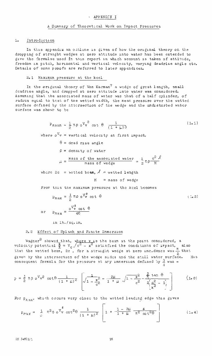
In this appendix an odtline 1s elven of how the ongIna theory on the dropplng of straight wedges at zero attitude into water has been extended to elve the formulae used fn this report 1n which account 1s taken of attitude, freedom in pitch, horizontal and vertical velocity, varying deadrise zzgle etc. Details of semz proofs are referred to later appendlces.
2,l Maximum pressure at the keel
In the orlglnal theory of Van Karman7 a wedge of great length, small deadrlse angle, and dropped at zero attitude into water "as considered. Assuming that the associated mass of water was that of a half cylinder, of radius equal to tr.at of tne wetsed width, the mean pressure over the wetted surface dnflned by %he rxiersectLon of the wed@ and the undisturbed water surface was shown tq be
P mean = ; xp ovv 2
cot e 1
(1 + VI3
where ovv = vertrcal velocity at flrrst Lmpact.
0 = dead rise angle
p = density of water
mas.s of the associated water 1 .2 1 IL= mass of wedge
= - znp M
where 2c = ketted beam,/ = wetted length
M = mass of wedge
From tnrs tne maximum pressure at the keel becomes
l np oVY cot % pmax = ;
0"; cot 0 oi- Pnax = 46
11, 1b.fsq.n.
2.2 Effect of Splash and Flnlte Immerslan
(1.1)
8 showed that, where x 1s the beam at the pant consldered, a ve13c:4~.n;:tantlal $ = VC,/= satisfied the condltlons of rlrpact, also that the wetted beam, 2c , for a straight wedge at zero incidence was$that
@ven by the lntersectlon of the wedge sides and the St111 watsr surface. HlS consequent formula for the pressure +t ary lmmei-slon defined by t "as -
P=
For F,,,, wl-lsh occurs very close to the wetted leadIng edge %hls gives
(1.4)
DS 3IEC Ii : 16
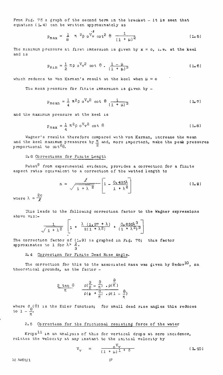
From FIG. 75 a graph of the second term III the bracket - it Is seen that equation (1.4) can be wrltten approxmately as
The minimum pressure at first lmmers~on 1s elven by x = o, 1.e. at the keel and 1s
P,lli = ; np ov”2 cot e . 1-b. I1 + Ll.)j Cl.61
which reduces to van Karman's result at the keel when k = o
The mean pressure for finite immersion IS gzven by -
pmean = 1 71zp 0”v” cot 6 1 4 11 + WI3
Il.91
and the maximum pressure at the keel IS
Wa@er's results therefore compared with "on Karman, increase the mean and the keel maximum pressures by; and, more unportant, make the peak pressures pmport1ona1 to cot2R
2.0 Corrections for Flute Length
Pabst' from experunental evidence, provides a correctIon for a finite aspect ratlo equvalent to a correctlon of the wetted length to
1 II=
,J ------T
; _ 0.425h 1
+ A
1 1
+A" 1 - 2c
wnere A = 7
This leads to the following correction factor to the Wagner expressions above VIZ:-
?i (1.27 + A) 211 + k2)
The correction factor of (1.9) 1s graphed in Fig. 76; this factor approxl.mates to 1 for h' 2.
3 a.4 Correction for Flnlte Dead Rise Angle.
The correction for this to the associated mass was given by Sedovl', on theoretical grounds, as the factor -
where P (8) to 1 -so
1s the Euler function; for small dead PLS~ angles this reduces
n
2.5 Correction for the frlctlonal reslstrng force of the water
Kreps" rn an analysis of this for vertical drops at zero lncldence, relates the velocrty at any Instant to the lnltla.1 velocity by
V v, =
(1 + ",I"; + b (l.lOl
DS 34531/i 17
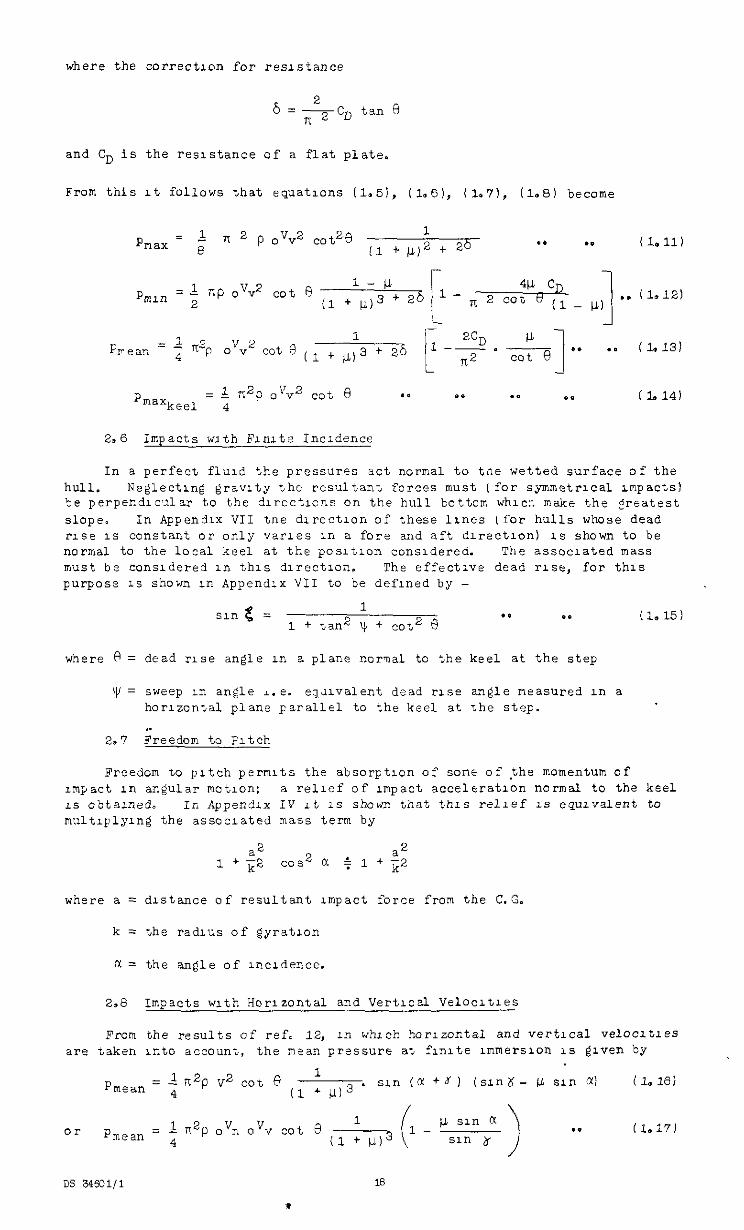
where the correction for resistance
6 =scD tan 0
and CD is the resistance of a flat plate.
From this rt follows that equations (1.51, (1.6), (la?'), il.81 become
1 bear, = ; "'p V2
1
1
ZCD il - o v cot 0 ( l + p) 3 + 26 l--.- *. .a
n2 cot e !
(1.131
2.6 Impacts with Flnlte Incrdence
In a perfect flud the pressures act normal to tne wetted surface of the hull. Neglecting gravity the resultant forces must (for symmetrical impacts) te perpexdlc~~1z.r to the d~reciilcns on the hull bottom whlcr. make the Ertatest SlOP e. In Appendxi VII tne dlrectlon of these lines ,for hulls whose dead rise IS constant or only .ial-~es in a fore and aft dlrectlon) 1s shown to be normal to the local keel at tt.e posltlon consldered. The associated mass must be considered =n this dlrectlon. The effective dead rise, for this purpose IS shown rn Appendix VII to be defined by -
sln g = 1 + lan2 ; + co+2 * *’ *e (1.15) I)
where Fi = dead rlse angle LT~ a plane norval to the keel at the step
yl = sweep 1x3 angle i.e. equvalent dead rise angle measured in a horizontal plane parallel to the keel at %he step.
,. 2.7 Freedom to Fitch
Freedom to pitch permits the absorptron of some of the momentum of mpact III angular mat1on: a relief of Impact acceleration normal to the keel LS obtarned, In Appendix IV it 1s shown that thrs relief 1s equivalent to multlplylng the associated mass term by
a2 a2 1 fk2 cos2 c( + 1 + ;2
where a = distance of resultant impact force from the C.G.
k = the radius of gyration
CI = the angle of lncrdence.
2.8 Impacts uth Horizontal and Vertical Velocltles
Fmm the results of ref. 12, 11, which horlzoctal and vertical velocltles are taken into account, the aean pressure at flnlte lmmerslon IS grven by
1 i+p ."n a", 0 1
or pmean = cot 4 (1 + 1113
DS 34601/l 18
*
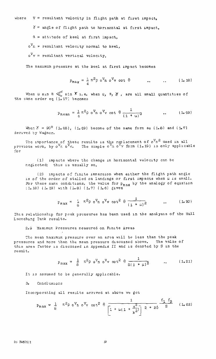
where V = resultant velocity Fn flight path at first Impact,
8= angle of flight pa%h to horizontal at first Impact,
c( = attitude of keel at first impact,
0'1, = resultant velocity normal to keel,
OV" = resultant vertl.ca1 velocity,
The maximum pressure at the keel at first Impact becomes
.a . . ( 1. 18 I
When U sin CI < sin x 1-e. when U, CQ Zr , < are all small quantities of the same order eq (1,17! becomes
1 pmeau 4 = L i12p ovn ovv cot 9
(1 + u13 . . (1. '19 1
When~ = 90' (l.M), iL(L9) become of the same form as (lee) and (laG'1: derived by Wa@er.
The xnportance of these results IS the re lacement of o n 9
' ' used in all previous work, by ovn ovv. The su,,ple ovn o Y form (1.15) 1s only applrcabIe foor
(1) impacts where the change in horizontal velocity ten be neglected: this 1s ueually so,
(2) unpacts of flnlte lmmerslon when either the flight path angle IS of the order of stalled on landings or first impacts when U 1s small. For these same condltlons, the value for pmax by the analogy of equation ;1.181 (1.19) with (1.8) (1.71 (1.6) $rves
1 Pmax = 8 rr2p 0% OV" cot2 9 (1 : u)2 . . (Lu?)
This relationship for peak pressures has been used xn the analysis of the HUG Launching Tank results.
2.9 Maximum Pressures measured on Finite Areas
The mean maxlmilm Pressure over an area ~111 be less than the peak pressures and more than the mean pressure dlscussed above. The value of this area Z-actor 1s discussed rn Appendix II and 1s denoted by S Ln the result.
It 1s assumed to be generally applicable.
3. Conclusions
Incorporating all results arrived at above we get
1 1 K2P .vn OV” cot2 e fl pmax = s S (1.221
DS 31601/l
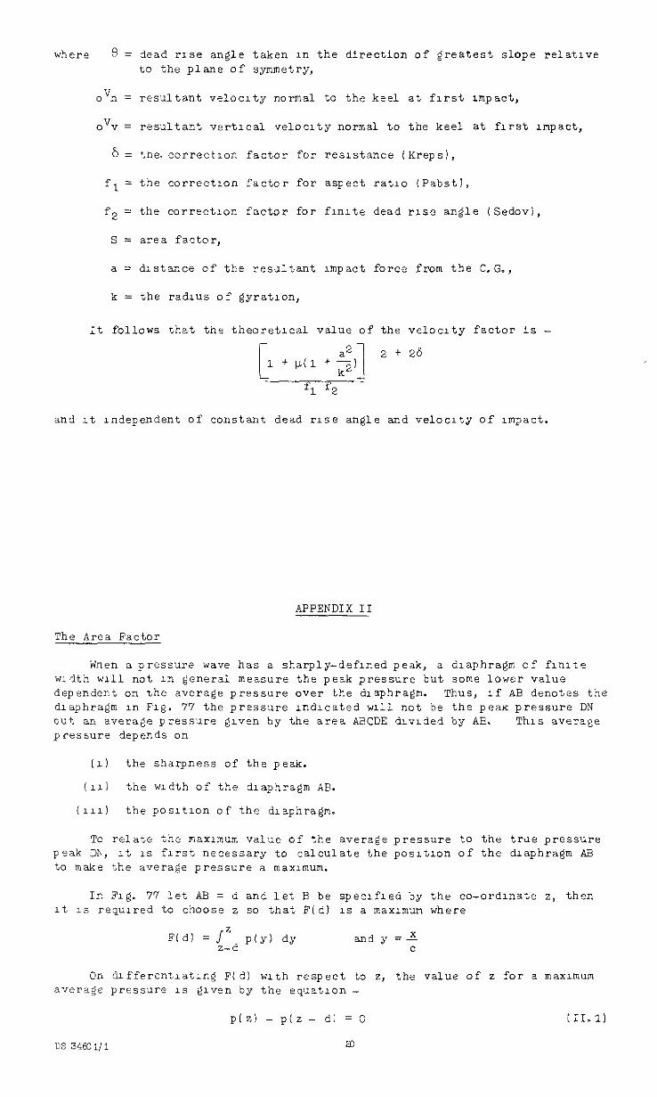
where 8 = dead rrse angle taken in the direction of greatest slope relative to the plane of symmetry,
0% = resultant velocity normal to the keel at first nnpact,
o'v = resultant vertical veloelty normal to the keel at hrst Impact,
6 = tne. correction factor for resistance (Kreps),
f 1 = the correctIon factor for aspect ratlo iPabst1,
f2 = the correction factor for flnlte dead ruse angle (Sedovl,
s = area factor,
a = drstance of the re:sJltant Impact force from the C.G.,
k = the radius of gyration,
It follows that the theoretIca value of the velocity factor 1s - -
!
32
1
2 + 26 1 + p(1 + -1
k2 - fl f2
and rt Independent of constant dead rise angle and velocity of Impact.
APPENDIX II
The Area Fzctor
Wnen a pressure wave has a sharply-defined peak, a diaphragm of funte width wlil not III general measure the peak pressure but some lower value dependent on \he average pressure over the diaphragm. Thus, If AB denotes the diaphragm in Fig. 77 the pressure lndlcated will not be the pea pressure DN out an average pressure given by the area AaCDE drvlded by AB. This average pressure depends on
(1) the sharpness of the peak.
(111 the width of the dlaphra@n AB.
(111) the posltlon of the draphragm.
TO relate the maxnnum value of the average pressure to the trae pressure p-ak Dh, It 1s first necessary to calculate the posltlon of the diaphragm AE to make the avera@ pressure a maximum.
In Fig. 77 let AB = d and let E be speclfled by the co-ordinate z, then It 1s requred to choose z so that F(d) 1s a maximum where
F(d) = j" z-d P(Y) dy andy=-ti c
On differentlatlng Fld: with respect to z, the value of z for a maxunum average pressure 1s @ven by the equation _
p(z) - p(z - d) = 0 :II.l)
OS 34Eo1/1 a
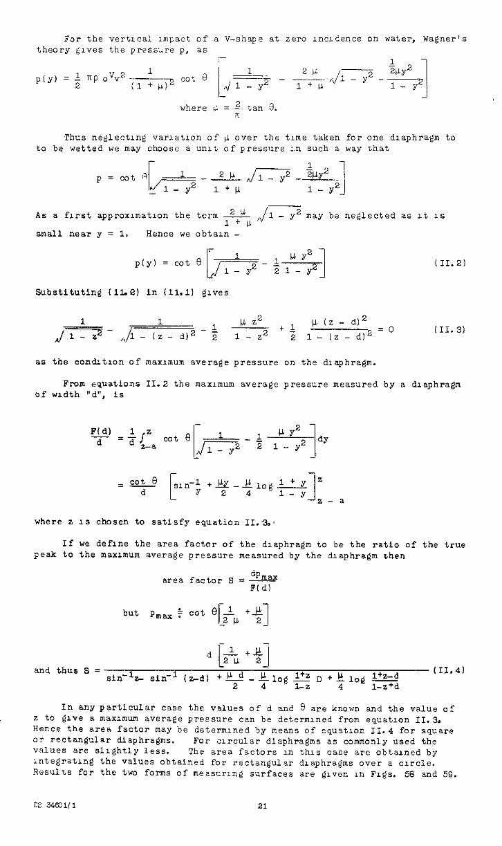
F2r the vertical Impact of a V-shape at zero lnadence on water, Wagner's theory gives the pi-eesdre p, as
where iL =Atan 8. K
Thus neglecting var~atlon of il over the time taken for one diaphragm to to be wetted we may choose a unit of pressure in such a way that
As a first approxlmatlon the term
small near y = 1. Hence we obtain -
may be neglected as It 1s
(II.21
Substituting iae) in (11.1) gives
dj2 - $ l.b (z - di2
l- (z - d12 =' (II.31
as the condltlon of maxunum average pressure on the diaphragm.
From equations of width "d", is
II.2 the maximum average pressure measured by a diaphragm
F(d) d
where z IS chosen to satisfy equation II.%
If we define the area factor of the diaphragm to be the ratio of the true peak to the maximum average pressure measured by the diaphragm zhen
dhlW area factor s = - F(d)
but pmax
and thus S = SW1 -I (z-d) +w d -$Jog g D +$log l+z-d
(II.41 z- sin -
2 l-z+d
In any particular case the values of d and 8 are known and the value of z to give a max~"um average pressure can be determIned from equation 11.3. Hence the area factor may be determlned by meane of equation II.4 for square or rectangular diaphragms. For circular diaphragms as commonly used the values are slightly less. The area factors in this case are obtained by lntegratlng the values obtained for rectangular diaphragms over a circle. Results for the two forms of meaxr~ng surfaces are glvcn rn Figs. 58 and 5s.
cs 3460 i/ 1 21
APPENDIX III
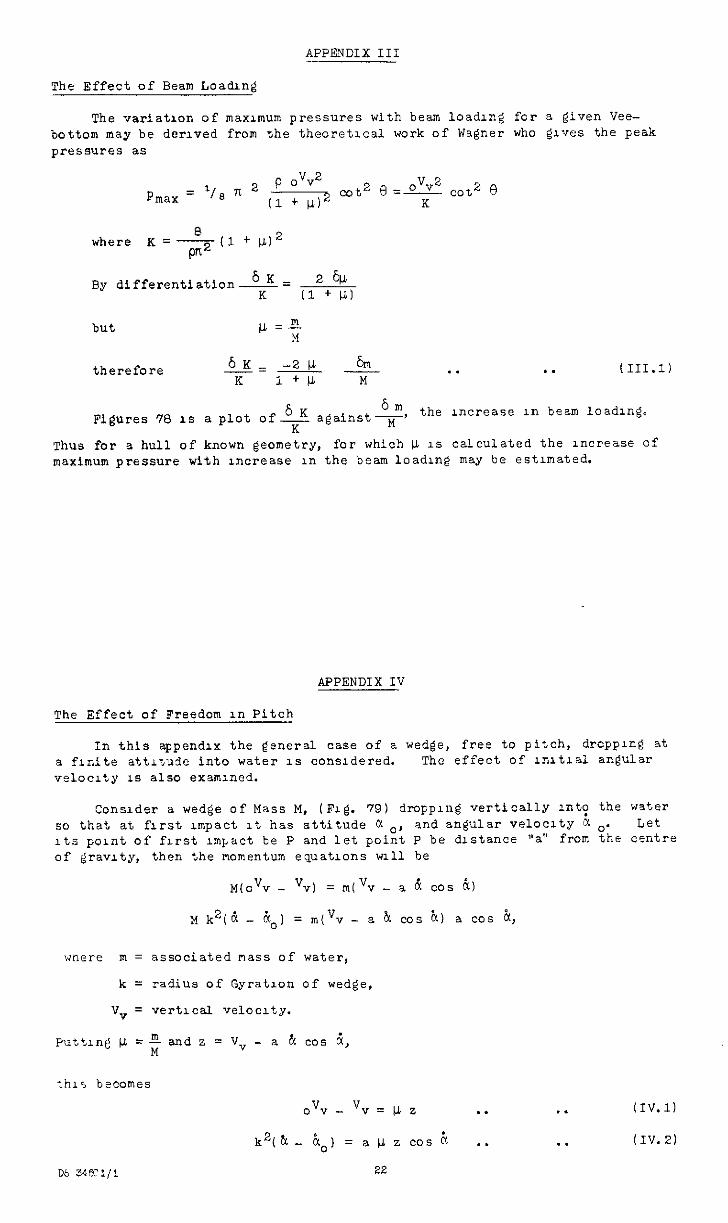
The Effect of Beam Loading
The variatron of maxunum pressures with beam loading for a given Vee- bottom may be derived from the theoretical work of Wagner who gl*?es the peak pressures as
118 n 2 p .““2
Pnax = (1 + IL12 Cot2 0 &!!2 d2 0
K
where K = - I1 + w2
6K- 2& By dlfferentiation-- K (1 + LL)
therefore 6K--2 & --l+b K M
. . . . (III.11
6K 6m Figures 78 IS a plot of- against -$f-' the increase in beam loadng.
K Thus for a hull of known geometry, for which & 1s calculated the increase of maximum pressure with uxxease in the beam loading may be estimated.
APPENDIX IV
The Effect of Freedom in Pitch
In this appendix the general case of z wedge, free to pitch, drcpplng at a finite atti?nde into water 1s considered. The effect of lnltlal angular velocity 1s also examined.
Consider a wedge of Mass M, (Fig. 79) drOppl"g Vertically St? the water so that at first Impact It has attitude c( o, and angular velocity N 0. Let Its paint of first Impact be P and let point P be distance "a" from the centre of gravity, then the momentum equations ~111 be
M(o"v - V,) = rrllVv - a c? cos i,
M k2(8 - "1,, = m('v - a & ~0s h) a cos k,
'"Jtlfre m = associated nass of water,
k = radius of Gyration of wedge,
V-? = vert1c2.l ve1oc1ty.
PuttInt w =; and z = V, - a b( cos 6,
k’(&.. $) =aWZCOSk . .
22
. . (IV.1)
. . (IV.21
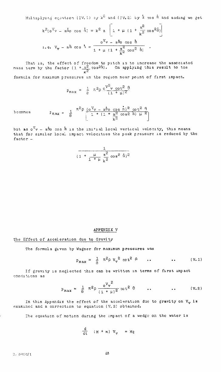
Thet IS, the effect of freedom to pitch 1s to :ncreasr the assnclated mass serm by the factor (1 +S.!?COs2~).
K2 On applying %hls result to tne
formula for maximum pressures in the region near pant of first Impact.
Pmzx = 1 n2p 0 V2Y cot2 3
8 (1 + I.li2
but as o"v - a.& cos k 1s the lnl+lal local vertical velocity, this means that for slmllar local Impact velocltres the peak pressure 1s reduced by the factor -
1 -
(1 + J-- - cos a2
1+ li k2 2 i)”
APPENDIX V
The Effect of Acceleratron due to Gravity
The formula given by Wagner for maximum pressures was
pmax = 8 1; n2p V"2 cot2 3 *. . . (V.1)
If gravity 1s neglected this can be written in terms of first 1mpaCt
condli,lons a5
1 n2p ovv
2
pmax = 8 (1 + lJ12 co:2 e . . . . 1V.2)
In this Appendix the effect o f the acceleration due to gravity on V,is examined and a correction to equation (V.2) obtained.
:he equuatlan of motion dwng the xnpact of a wedge on the water is
d dt CM + ml v, = Mg
23
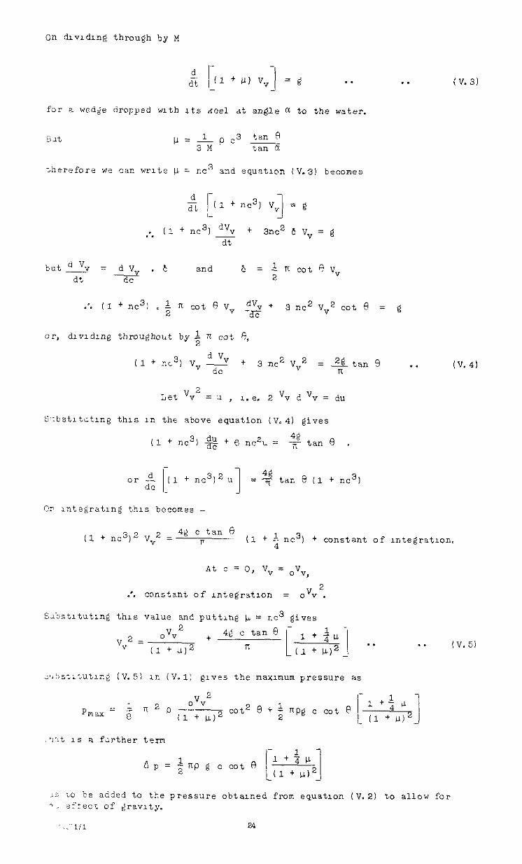
On dlvrdlnd through by ,Y
d - clt, Il+P)v.{ =g . .
-
for a wd;e dropped mth Its xeel at angle a to the water.
. . (V.3)
;hsrefore we can write or. = m3 snd equation (V-3) becomes
dr - dt I3 + nc31 v, = g I- J
,.. (1 + nc3) d”” + 3nc2 c vv = g dt
but% = dV .E ---;--v
and 6 dt
= L K cot 0 v,
QC 2
.a. (1 + n21 I $ n cot 0 v, dV” + 2 a?
3 nc2 v ” cot0 = g
(1 + nc3) v d Vv YdC
+ 3 i-K2 vv2 = zg tan 5 . . iv.41 n
Let Vv2 = II , A.% 2 'v d Vv = du
Sl:bstltotmg this in tht above equation (V-4) gives
(1 + Id) d" <
E + 6 nA = *tan0 ,
O? rnte$jratlng this becomes -
(1 + nc3)2 v 2 = 42 c tan 0
Y ~ (1 + $ nc3) + constant of rntegratmn.
At c = 0, V,= oVy
2 .'* constant of rntegratron = 0V.J .
S>bstltutrng this value and puttlng u = .c3 gives
A p = + np g c cot 0 1 +$p
I ! (1 + LL)2
. . (V.51
15 ic be add?d to the pressure obtamed from equation (V.2) to allow for 1. s:xecr ef gravity.
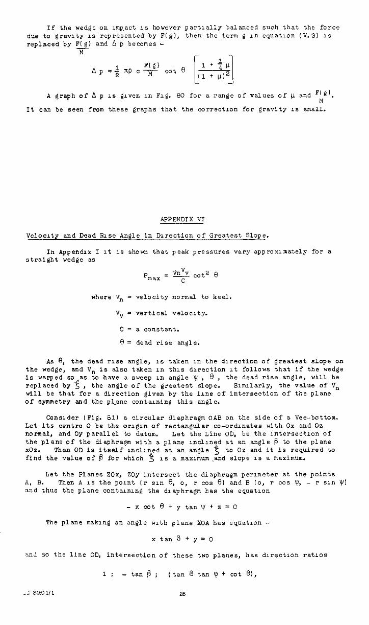
If the wedge on Imp-act IS however partially balanced such that the force due to gravity 1s represented by F(g), then the term g in equation (V.31 1s replaced by F(g) and a p becomes -
M
Ap =$ F(g)
nP c -izf- cot e 1+&h
I1 + LLJ2 -
A graph of A p 1s @ven in Fig. SO for a range of values of fi and F;gl.
It can be seen from these graphs that the correctx)n for gravity IS small.
APPENDIX VI
Velocity and Dead Rise Angle in DIrection of Greatest Slope.
In Appendix I It 1s shown that peak pressures vary approxlraately for a straight wedge as
P vnv.? max = - cot2 e
C
where Vn = velocity normal to keel.
vv = vertical ve1oc1ty.
c = a constant.
8 = dead rise angle.
As 8, the dead rrse angle, 1s taken in the dlrection of greatest slope on the wedge, and Vn is also taken in this dlrection lt follows that if the wedge is warped so as to have a sweep in angle Y, 0, the dead rise angle, will be replaced by 3, the angle of the greatest slope. Sunllarly, the value of Vn will be that for a direction given by the line of intersection of the plane of symmetry and the pl.ane contuning this angle.
Consider (Fig. 61) a circular diaphragm OAB on the side of a &e-bottom. Let its centre 0 be the orlgln of rectangular co-ordinates with Ox and Oz normal, and Oy parallel to datum. Let the Line OD, be the lntersectlon of the plane of the diaphragm with a plane lncllned at an angle p to the plane X02. Then OD is Itself rnclrned at an angle '$ to Oz and it is required to find the value of b for which 3 1s a maxunum.and slope IS a maximum.
Let the Flanes 20x, ZOy intersect the diaphragm peruneter at the points A, B. Then A IS the point (i- sin 8, o, P cos 8) and B (0, r cos Y', - r sin v/j and thus the plane contarnlng the dl.aphragm has the equatron
- x cot e + y tan y + z = 0
The plane makIng an angle wrth plane XOA has equation -
xtana+y=o
2nd so the line OD, intersection of these two planes, has dlrectlon ratios
1; - tan p ; (tan 8 tan v, + cot 81,
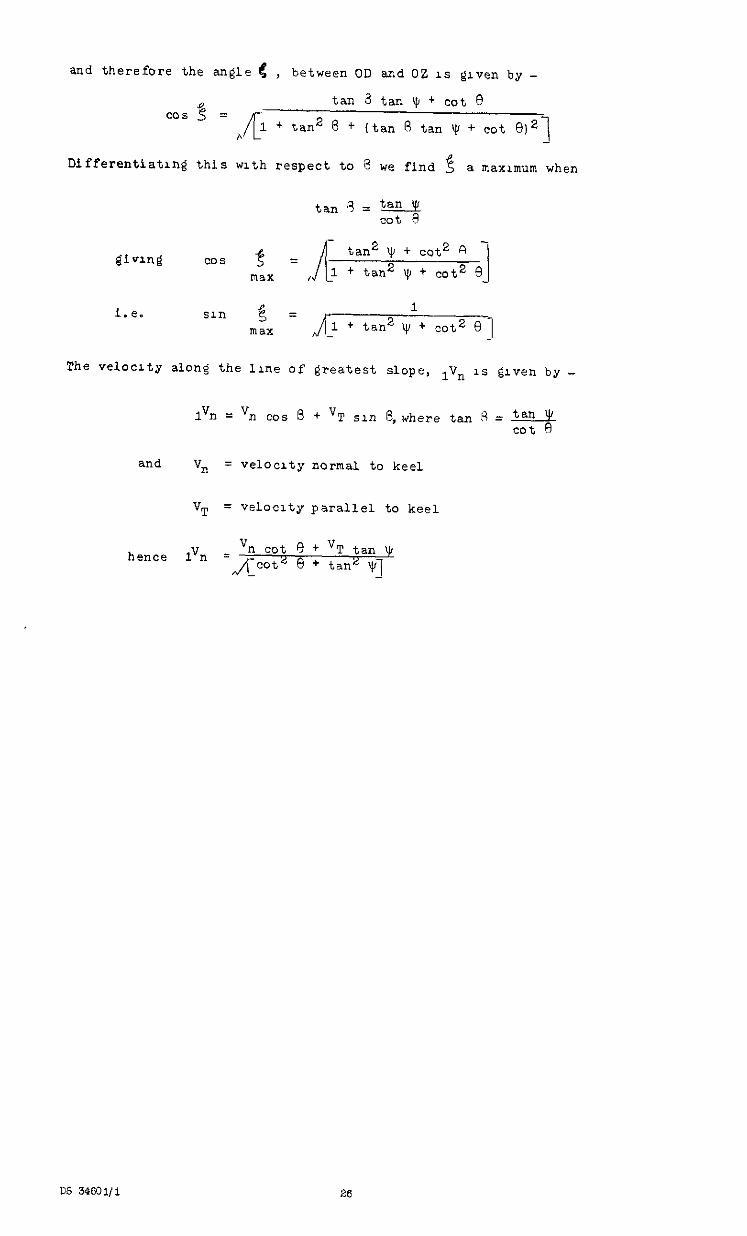
and therefore the angle 6 , between OD and 02 1s @ven by -
Differentiatmg this with respect to 8 we find f a max~~m when
1”il = VII cc..5 8 + V T sin &where tan 8 = 3
and "n = velocity normal to keel
VT = velocity parallel to keel
hence Ivn = Vi-l cot 0 + VT tan !$I
n/cot2 0 + tanL q _
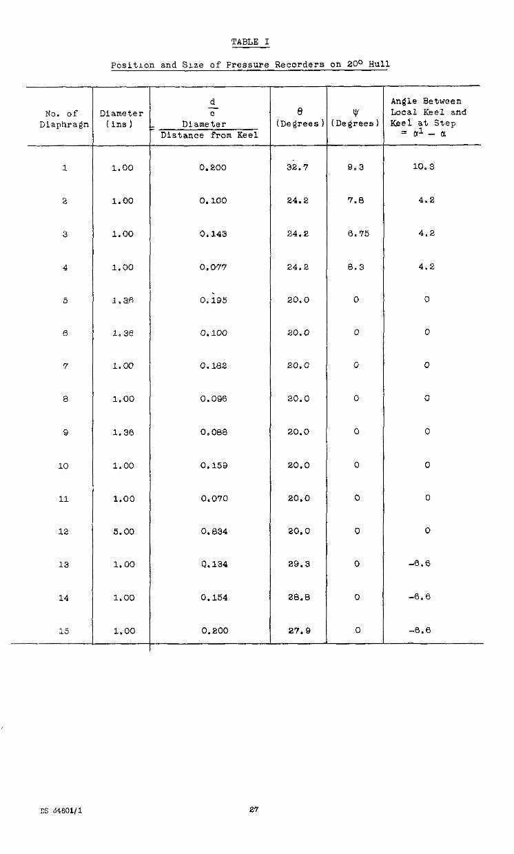
TABLE I
Position and Sue of Pressure Recorders on 20° Hull
No. of Diaphraen
1
2
3
4
5
6
7
8
9
10
11
12
13
14
15
Diameter ( ins 1
1.00
1.00
1.00
1.00
3.m
1.36
1.00
1.00
1.36
1.00
1.00
5.00
1.00
1.00
1.00
d c
Diameter Distance from Keel
e (De@'ees
0.200 32.7
0.100 24.2
0.143 24.2
0.077 24.2
0. ;95 20.0
0.100 20.0
0.182 20.0
0.096 20.0
0.088 20.0
0.159
0.070
0.834
9.134
0.154
0.200
20.0
20.0
20.0
29.3
28.8
27.9
v Degrees)
9.3
7.0
0.75
8.3
0
0
0
0
0
0
0
0
0
0
0
Angle Between Local Keel and Keel at Step
= ul - ti
10.3
4.2
4.2
4.2
0
0
0
0
0
0
0
0
-6.6
-%.%
-%.%
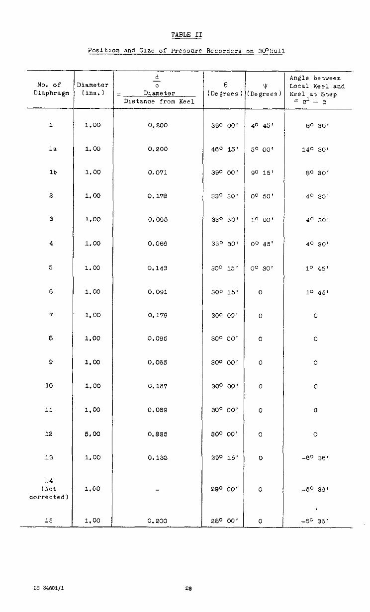
TABLE II
Position and Size of Pressure Recorders on 3O'Hull
No. of 1 Diameter Diaphragm 1 (ins. 1
1
la
lb
2
3
4
5
6
7
8
9
10
11
12
13
14 t Not
corrected
15
1.00
1.00
1,oo
1.00
1.00
1.00
1.00
1.00
1.00
1.00
1.00
1.00
1.00
5.00
1.00
1.00
1.00
d c
: Diameter Dutance from Keel
0.200
0.200
0.071
0.170
0.095
0.066
0.143
0.091
0.179
c.095
0,065
0.167
0.059
0.835
0.132
0.200
390 00'
4.30 15'
390 00'
330 30'
330 30'
330 30'
3oc 15'
300 15'
300 00'
300 00'
300 00'
300 00'
300 00'
300 00'
290 15'
290 00'
260 00'
40 45'
50 00'
SO 15'
00 50'
10 00'
00 45'
00 30'
0
0
0
0
0
0
0
0
0
0
Angle between Local Keel and Keel at Step
za1-a
80 30’
140 30'
8" 30'
40 30'
40 30'
40 30'
10 45'
10 45'
0
0
0
0
0
0
-60 36'
-e'O 36'
-60 36’
No. of Diaphragm
1
la
lb
2
3
4
5
6
7
a
9
10
11
12
13
14 I Not
corrected]
15
TABLE III
Posltlon and Size of Pressure Recorders on lo0 Hull
11ameter (ms. 1
1.00
1.00
1.00
1.00
1.00
1.00
1.00
1.00
1.00
1.00
1.00
1.00
1.00
5.00
1.00
1.00
1.00
d c
Diameter Distance from Keel
0.250 210 50' lo 25' 100 12'
0.222
0.131
0.250
0.114
0.074
0.182
0.083
0.200
0.105
0.071
0.200
0.077
0.862
0.132
0.200
300 00' B" 00' 100 45'
23O 00' 16O 35'
130 40'
140 00'
140 20'
100
100
100
100
100
100
100
loo
290
290
280
80 40'
20 20'
120 36'
170 10'
10 CO'
80 30'
00
00
00
09
00
00
00
00
00
50 25'
So 25'
5O 25'
CO
00
00
CO
00
00
00
00
-60 36'
-60 36'
-60 36'
8 Degrees
-
v Degrees)
Bngle between Local Keel and <eel at step = al - x
lx 34601/l 29
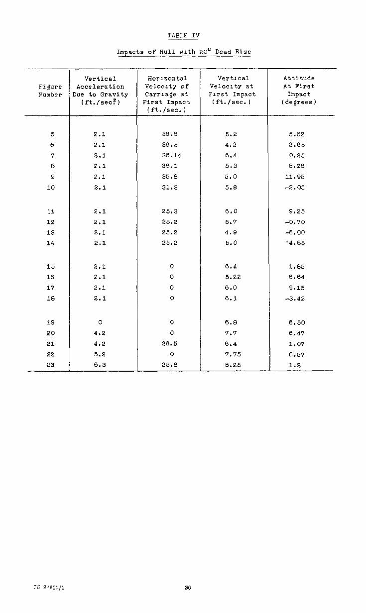
TABLE IV
Impacts of Hull with 20' Dead Rise
Figure Number
5
0
7 8
9
10
11
12
13
14
15 16
17
18
19
20
21
22
23
Vertical Acceleration
he to Gravity (ft./WC?)
Horizontal Velocity of carriage at
First Impact (ft. /sec. I
vert1ca1 Attitude Velocity at At First First Impact Impact
(ft./set.) (degrees)
2.1 36.6 5.2 5.62
2.1 36.5 4.2 2.65
2.1 30.14 6.4 0.25
2.1 36.1 5.3 8.26
2.1 35.8 5.0 11.95
2.1 31.3 5.8 -2.05
2.1 25.3 6.0 9.25
2.1 25.2 5.7 -0.70
2.1 25.2 4.9 -6.00
2.1 25.2 5.0 +4.a5
2.1 0 6.4 1.85 2.1 0 5.22 6.64
2.1 0 6.0 9.15
2.1 0 6.1 -3.42
0 0 6.8 6.50 4.2 0 7.7 6.47
4.2 26.5 6.4 1.07 5.2 0 7.75 6.57
6.3 25.8 6.25 1.2
IS 39301,1 30
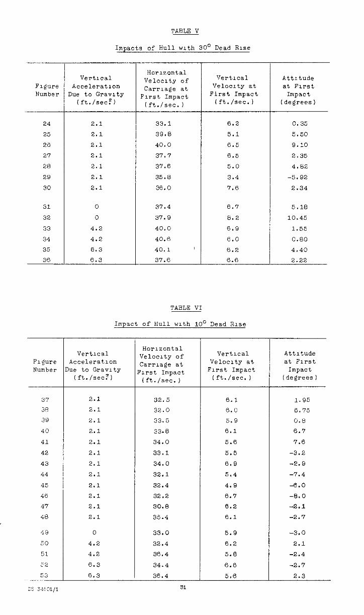
TABLE V
Impacts of Hull with 30' Dead Rise
F'lgure Number
24
25
26
27
28
29
30
31
32
33
34
35
36
-
1
-
F1gJre Number
37
38
39
40
41
42
43
44
45
46
47
48
Vertical Acceleration
he to Gravrty (ft./%x!?1
Horizontal Velocity of carriage at
First Impact lft./sec.)
vert1ca1 Attitude Ve1oc1ty at at First
First Impact Impact (ft./SC.) (degrees)
2.1 33.1 6.2 0.35
2.1 39.8 5.1 5.50
2.1 40.0 6.5 9.10
2.1 37.7 5.5 2.35
2.1 37.6 5.0 4.82
2.1 35.6 3.4 -5.92
2.1 36.0 7.6 2.34
0 37.4 6.7
0 37.9 8.2
4.2 40.0 6.9
4.2 40.6 0.0
6.3 40.1 1 6.2
6.3 37.6 0.6
5.18
10.45
1.55
0.80
4.40
2.22
TABLE VI
Impact of Hull with 10' Dead Rise
vert1ca1 Acceleration ue to Gravity
(ft./set?)
, F
6.3
2.1
2.1
2.1
2.1
2.1
2.1
2.1
2.1
2.1
2.1
2.1
2.1
0
4.2
4.2
6.3
Horizontal Velocity of carriage at 'lrst Impact (ft./%x.)
Vertical Attitude Velocity at at First
First Impact Impact Ift./sec. ) (degrees)
32.5 6.1 1.95
32.0 6.0 6.75
33.5 5.9 0.6
33.6 6.1 6.7
34.0 5.6 7.6
33.1 5.5 -3.2
34.0 6.9 -2.9
32.1 5.4 -7.4
32.4 4.9 -0.0
32.2 6.7 -8.0
30.8 6.2 -2.1
35.4 6.1 -2.7
33.0 5.9 -3.0
32.4 6.2 2.1
36.4 5.6 -2.4
34.4 6.6 -2.7
30.4 5.6 2.3
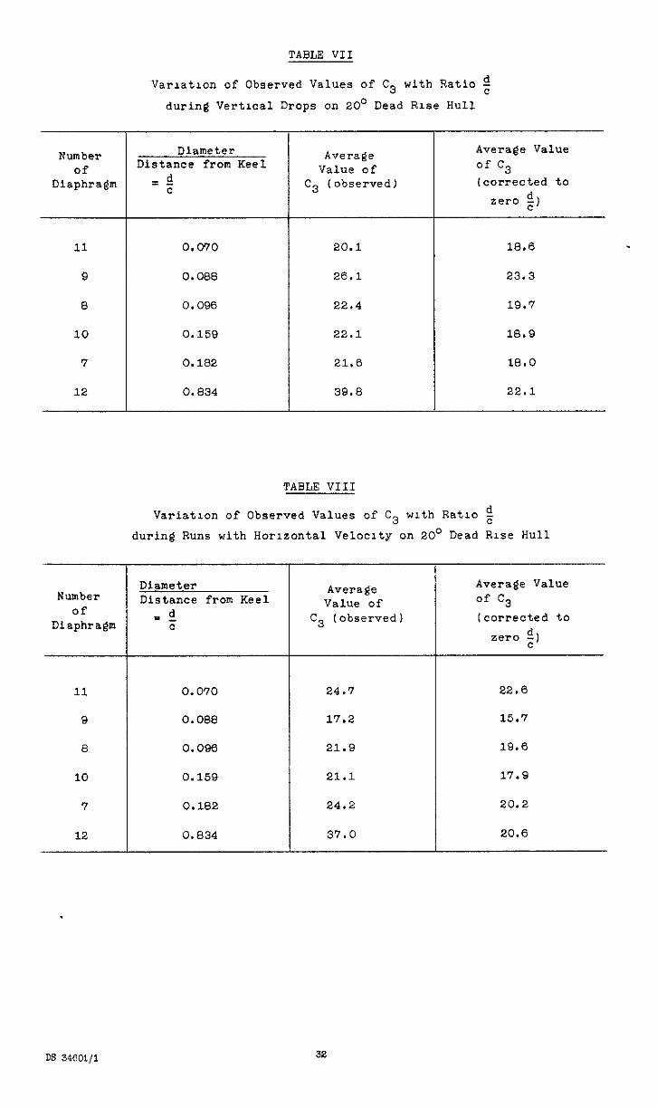
TABLE VII
Number of
Diaphragm
11
9
8
10
7
12
Varlatlon of Observed Values of C3 with Ratio 2
during Vertical Drops on 20' Dead Rise Hull
Diameter Distance from Keel
=s! c
0.070 20.1 18.6
0.088 26,l 23.3
0.090 22.4 19.7
0.159 22.1 18.9
0.182
0.834
21.0
39.8
18.0
22.1
Number of
Diaphragm
11
9
8
10
7
12
Average Value of
C3 (observed)
-
Avera@ Value of c3 (corrected to
zero g,
TABLE VIII
Variation of Observed Values of C3 with Ratlo 2
during Runs with Horizontal Velocity on 20' Dead Rise Hull
Diameter Distance from Keel
d =- c
0.070 24.7
Average Value of c3
Icorrected to
zero $1
22.8
0.088 17.2 15.7
0.096 21.9 19.6
0.159 21.1
0.182
0.834
24.2
37.0
17.9
20.2
20.6
Average Value of
C3 (observed)
DS 34801/l 32
Number of
Diaphragm
9
11
8
10
7
12
Number of
Diaphragm
5
6
8
9
10
11
TABLE IX -__
Varlatlon of Observed Values of C3
with Ratlo t for 30' Dead Rise Hull
Diameter Distance from Keel
d = - c
0.065 20.8 20.0
0.069 21.1 20.3
0.095 27.7 26.0
0.167
0.179
0.835
20.4 1e.s
30.0
34.6
27.3
26.0
Average
Value of C3 (observed)
TABLE X
Variation of Observed Value of C3 with Ratlo g
and Distance Forward of the Step for 10' Hull
Avera$e Value of c3
(corrected to
zero ;,
Diameter Distance from Keel
d =- c
0.182
0.083
0.105
0.071
0.200
0.077
Average Value of
f3 (observed)
21.8
22.6
16.1
20.5
10.2
8.8
Average Value of '23 (corrected to
zero 2 )
11.5
15.6
10.2
18.9
5.3
6.1
I )lstance Forward of C.G. Beam
1.12
0.46
0.28
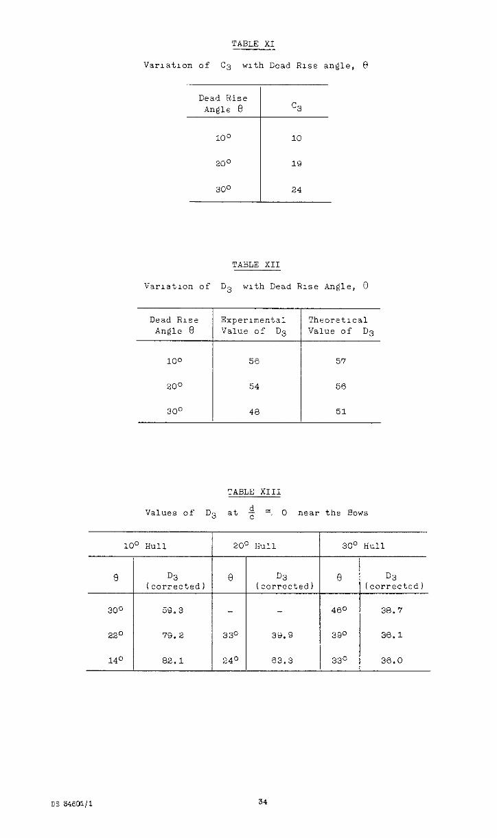
TABLE XI
Variation of c3 with Dead Rise angle, 8
Dead Rise An@le 8 c3
100 10
200 19
300 24
TABLE XII
Var~atlon of D3 with Dead Rise Angle, 8
Dead Rise Experlmentai TheoretIcal Angle 0 Value of D3 Value of D3
100
200
300
5s
54
48
57
56
51
TABLE XIII
Values of D3 at c d =, 0 near the Bows
100 Hull 20' Hull 30' Hull
I I
300 59.3 460 38.7
220 79.2 330 39.9 390 36.1
140 82.1 24'= 63.3 330 36.0
e D3 I I
I3 D3 (corrected) (corrected)
34
I’
--
TABLE XV
Comparison between Results of H.L.T, Forvula with Keel Przssures measured durng a Landing in a Soutnsmpton
at ovv = 3,G ft,./sec. v 1 135 ft,/sec. a=-o.5
Vrl $ cc&3 d Are2 ve1cc1ty P,, PIMX Gore-- -emu 'Ilax = 54 c
II Factcr Factor corrrctca ooserved
5 2.6 0.16 1.08 1.02 negllelble 2.4 7.5
7 2,7 0.45 1.35 1.01 3, 1.9 4.0

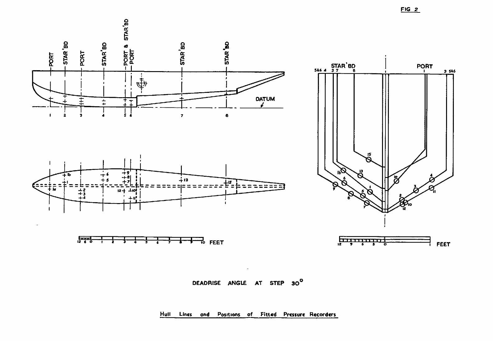
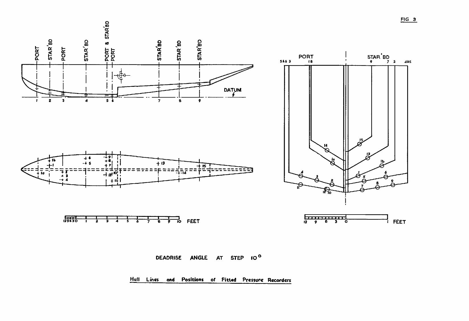
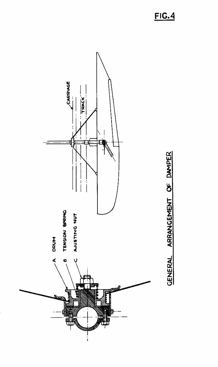
FIG.4
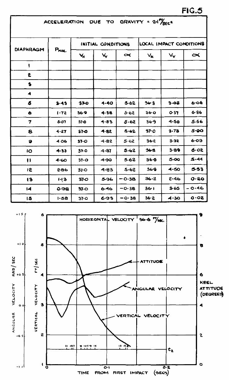
FIG.5 ACCELERATION DUE TO GRAVITY = ~47&,~
DlAPHRAGM
I5 I*58 37-o 6.93 -0~38 36.2 4-M 0.02
+1
6
6
2 4
-0
i
0
:
‘3
2
I
HORIZONTAL VELOCllY ’ 364 =/WC.
, VERTICAL VELOCITY
6
KEEL AvwwoE
TIME moii LlRSf IMPACT (4&j
ACCELERATION DUE TO ORAVITY = 247&
I DIAPHRAGM I INITIAL COWDIT\ONS I LOCAL IMPACT COUOlTlOr4S
2.81 38.8 2-35 2.65 35-S 4.78 3*6S
2.66 39-6 2.29 2-65 373 3.09 4.32
2.80 38.5 Z-Z8 246 363 2.69 4+54
3-62 38-l 2.23 2.65 36.5 3.33 4.4 I
3.47 1 38.7 2.65r 35-7 4-78 1 3-44
I-90 1 38-8 2.35 1 2.65 1 35.7 3.45
I.10 38-4 8.36 1 - 4.7 I- l-74
38.3 IO.96 I- 3.95 1 37.2 6.31 ) - 1.47
2.06 1 Se.2 13.47 I- 3.95 1 37.8 5.92 I- I.85
IO
+
6
KEEL ATTITUOE
-8 “̂ A. , . ” u YZ
TIME FRi ’ FIRST IMPACT (SfCS.)
FIG. 7 ACCELORATION DUE TO GRAVITY -- 2-l~~cce
2
3
4
6 3-b 35.2 8. I 2.25 35.5 7.01 I.53
6 3.m 95.3 a.14 2.25 36.0 5.63 I *46
8 1 4.44 1 35.2 1 7-18 1 2.25 1 35.3 1 6.85 1 I-50
a I 3.36 1 35.3 } 7.18 1 2.25 1 35.7 1 5-10 1 I.46
lo 4.34 35-2 6.93 2-25 35.6 6.25 I.46
II 3.53 35.2 7.00 2.25 35.7 6.98 I.96
I2 2-10 35.2 7.16 2*PS 35.6 7.05 2-04
I3 I.82 354 5 *69 - 4.35 36-O 3-78 0.06
I4 I *60 35.4 8-62 - 4.35 35.0 4.54 O-85
I6 2*0 354 2.59 - 4.35 35.8 3.96 0.36
I
i
HORIZONTAL VEL0Cll-f
n *, n., - . -s
-l-WE FROM FIRST IkiPACl- (srCS)
FIG. 8 1 ACCELERATION DUE TO GRAVITY = 2.1 FT/s~t:
DIAPHRAGM 1 I 3
4
5
6
7
8
9
IO
II
I2
13
4
0
P MAX
4-06
0.44
5.56 35.759 5.627 8.26 35.26 4.56 7.86
6.14 35.730 5.634 8.26 35.11 4.47 7.48
S-80 35.912 5.632 8.26 35-12 4.1 I 7.20
5.14 35.78 5 538 8,26 35.38 4.13 7.52
6~14
o-40 35.7351 4.6801 1.66 1 35.06 1 2.83 1 7.47
I.03 35.7071 4.2681 1.66 1 35.49 1 3.53 1 8.20
1.96 35.6U4 3.070 l-66 26.20 5.69 8.63
INITIAL COI’IDITIONS LOCAL IMPACT CCNDlTlON
v, vv 0-c % vv o<
35.793 5.328 8.26 35 *57 2.64 7.30
35.859 5-995 8.26 35.59 0.08 748
35.770 5.567 8.26 35.55 4.62. 8-03
35.759 5.627 826 35.20 4.47 7.77
1 HORIZONTAL VELOCI-I-Y 36.1 F1/5~c
\ I
VERTICAL VELOCITY /
ANCULAQ
VELOCIN
-7
IO
8
KEEL
ATTITUDE
(DEGREES)
6
4
2
TIME FROM FIRST IMPACT (DECS)
FIG.9 ACCELERATION DUE l-o CRAWTY = 2-l -/SEcP
DIAPHRAGM OCAL IMPACT CONDITI~S
6
6
TIME FROil.FIRST IMPACT’ (S=S)
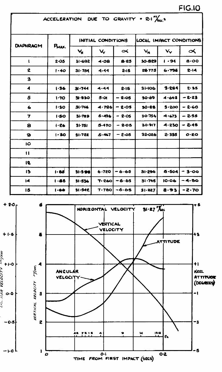
F IG.10 ACCELERATION DUE TO GRAVITY = d&a
r IoN9 I LOCAL IMGiAcT CONOITION!
I 2.05 31.692 4.08
2 I.40 31,754 4.44
3
4 I.36 8 0744 4.44
5 I -70 Y*1)SO 5.01
6 I*30 31.746 4,786
7 I.50 3bns 5.496
2.15 1 ,775I 60961 2.14
2.15 31.106
3=
-8-M 3069
- e.05 sosea - ,.,~to.7s+I 4.673 1 - 245
I 8 I lea I fb7sI I s-470 - 1.08 1 30.017 1 4.2301 - 2.4s
I+ =I-+= - 2.03 32.026 2.3% o-e0
I II ‘I IQ ‘~ I I3 1.d Sb598 6.720 -6-65 1 Jl.296/ 5.5041- 3.00
-6.65 1 31.&l IO.06 I-4.50 14
IS
I *SS 1la36 7. e60
1-w ws4e 7.780 -6.66 3l.az7 8.93 -2.70
4 + 24
-t
-t I(
(9
-,
--!
+ I.6 4
-1.0
t-
D~APHRAGW
I F 2
ACCKLKRATION OlJE TO GQAVITY = a.1 7&P
I 3
I 6 I 7
$3 IO es. 50 5-41 9.25 23.7 8.40 7.25
4.66 25.60 s-73 9-26 24.3 4 -94 a.40
I 8 4.6f OS*SO 5.7e 9. es 24.10 447 8. I7
I 9 I JO
3-60 e5*50 5.73 Pai 23.90 3.37 7.53
3.85 25.6Q 5-80 a. 25 24. IO 4.26 8.10
I II 1 4.74 1 ‘iS.60 1 5-77 1 9.25 1 24.90 1 4-98 ) 8.48
I2 3.14 C3.6.0 5.72 9.25 2440 4.55 8.22
13
14 0675 e5.60 6.a4 2.66 24-80 3.20 e-79
15 1’34 25-70 7.16 2-65 2S.M 6,OS 2.82
V-Z
TIME FROM%?Sl- IMPACT (SECS)
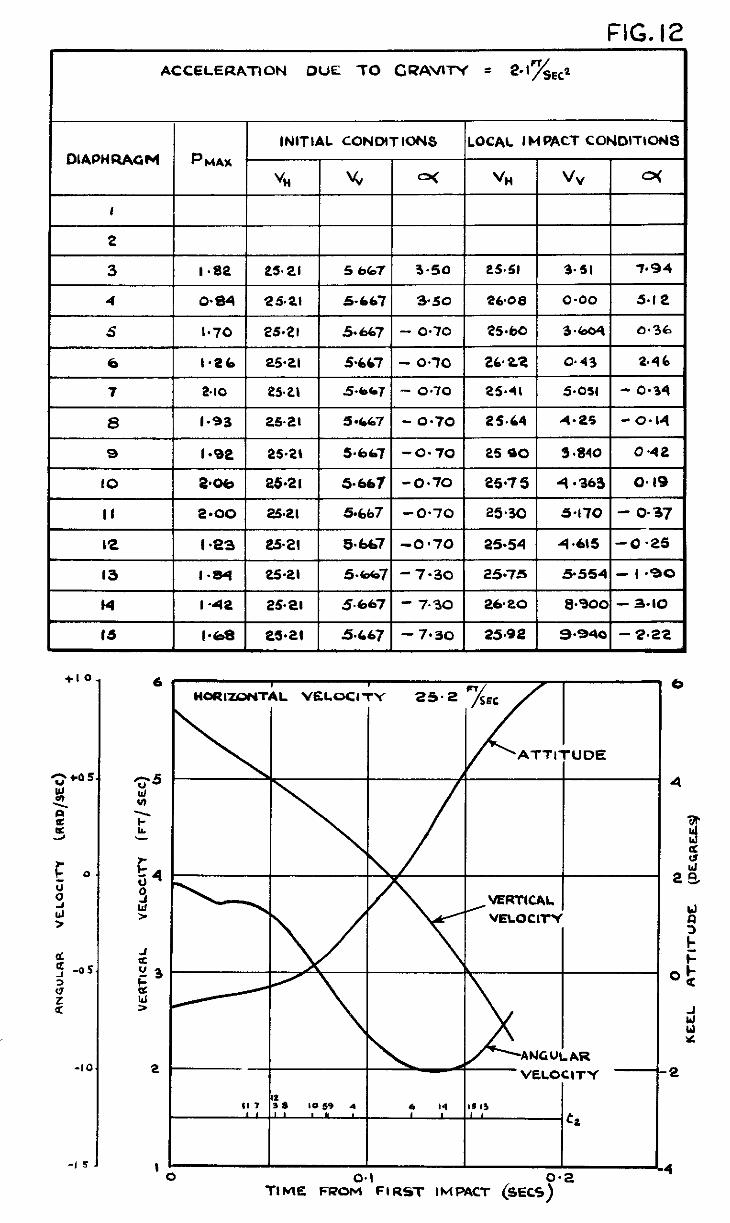
FIG. 12 ACCELERA-I-ION DUE TO CQhWlN = 2.17~~~2
-10
-1 5
6r
\
‘5 -
4-
3-
#
ZZ-
I- O
_,
-4 I
TIME FROM FIRST IMPACT (SECSj G
t
I II~~RI~ONTAL v(imaT~ es.19 ‘~5Lc .--..
\ /
/
TIME FROM FW?ST IMPACT (SECS)
ACCELEQATION DUE TO GRAVITY =24 7-a
I 3 1 e-50 25.30 1 4.826 4.845 26-W 2 -32 1 se0
6 2.06 25.283 4 -823 4 -845
7 3-30 25404 4.92 4.845
8 3-80 25.296 4.919 4-84s
I 9 I 3.1e I 2s.29aI 4-918 I 4-845
I IO I 3.*5 1 25.297I 4.9411 4-94s
25.18 1 2.80 1 5.88 1
I
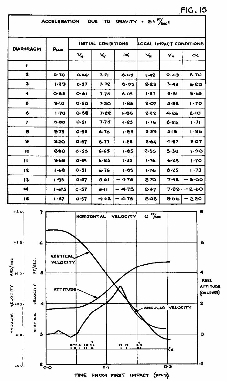
FIG. 15 ACCELERATION OUE TO GUAVITY = 2.1 ‘yggz
1 MAPMRAGM INITIAL CONDITIONS LOCAL IMPACT CONDITIONS
bw.
“i4 “v a< “H “v o<
I
Q o-70 0.60 7.71 6.05 l-42 2.69 8.70
I 4 I o-se I 0.61 I 7.75 I 6.05 I l-37 I 2.01 I 8-65
IQ I.68 o-51 6-75 I -a5 I -76 6.25 I *73
I3 I -93 0.57 5.61 - 4.75 2.70 7.45 - 3.00
I4 I -675 0.57 5.11 - 4.75 Q*?7 7*%9 -2.60
IS I-37 0.57 4.6Q - 4.75 2.00 8.06 - 2-20
vHfT\cIu,
VELDCITY
\
B
6
4
KEEL
LTTITUDE
jXCRER8)
a
0
e
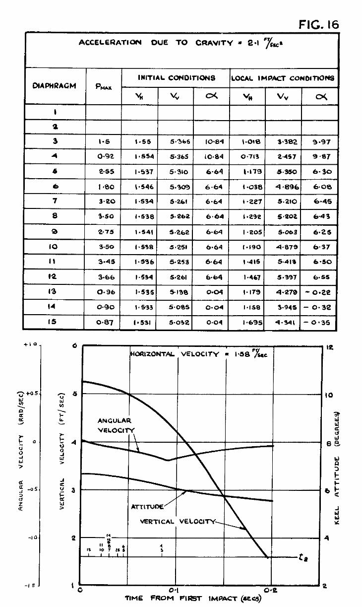
FIG. 16
6 I I*00 I b-546 1 5.3031 6.64 1 I.038 1 4.8961 6.00
I 3.20 1 I .534 1 52661 I 6.64 I I-2271 5.210 1 6.45
8 1 3.50 ( 1.538 1 5.2621 6.64 1 1.292 1 5.202 1 6.43
I 2.75 ( I.5411 5.262 1 6.64 1 I.2051 5.063 I 6.25
-1 5
VERTICAL VELOCIT
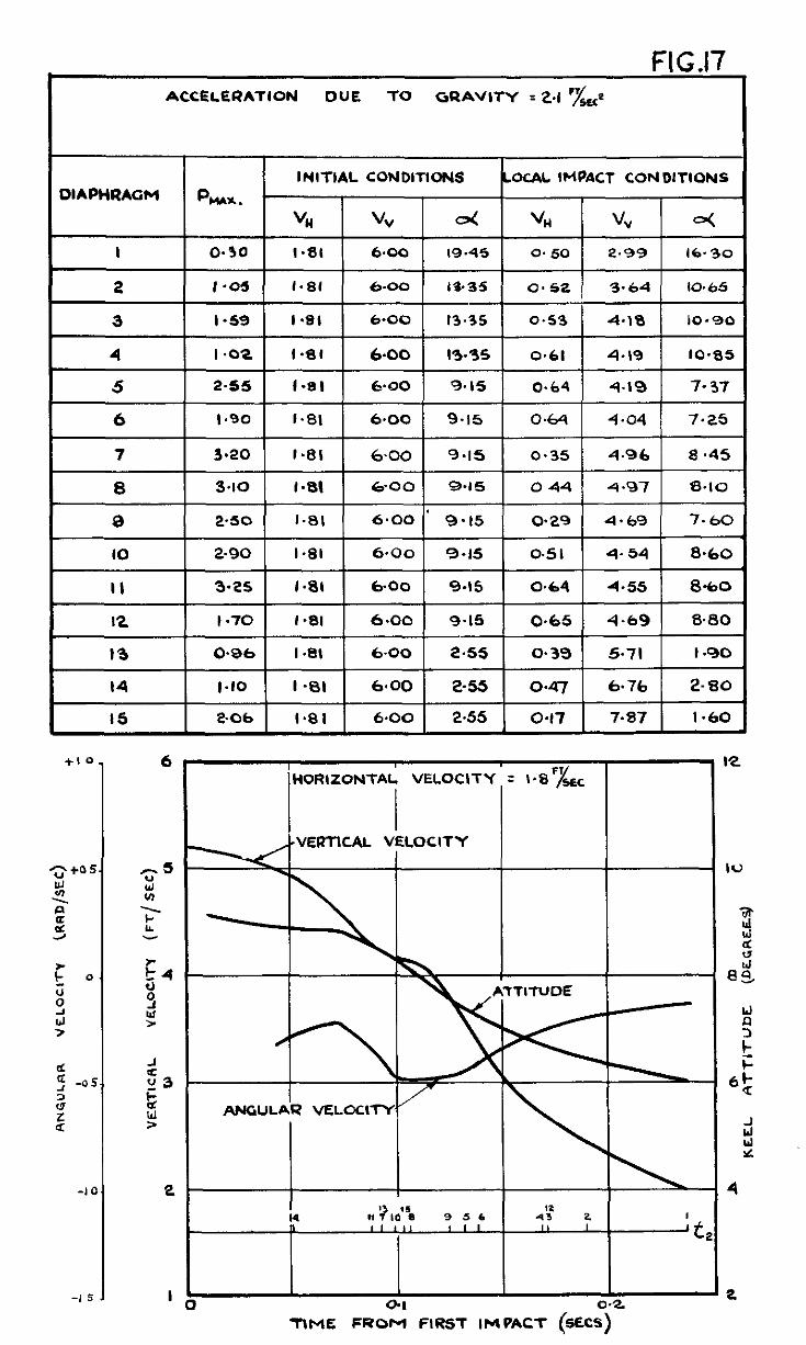
FIG 17 I IW.1.
ACCELERATION DUE TO GRAVITY I 2.1 F&
I5 I 2.06 6.00 2.55 ] 0.17 7.87 I *Ii0
VERTICAL VELOCITY
TIME FRO; FIRST IMPACT (SECi)-
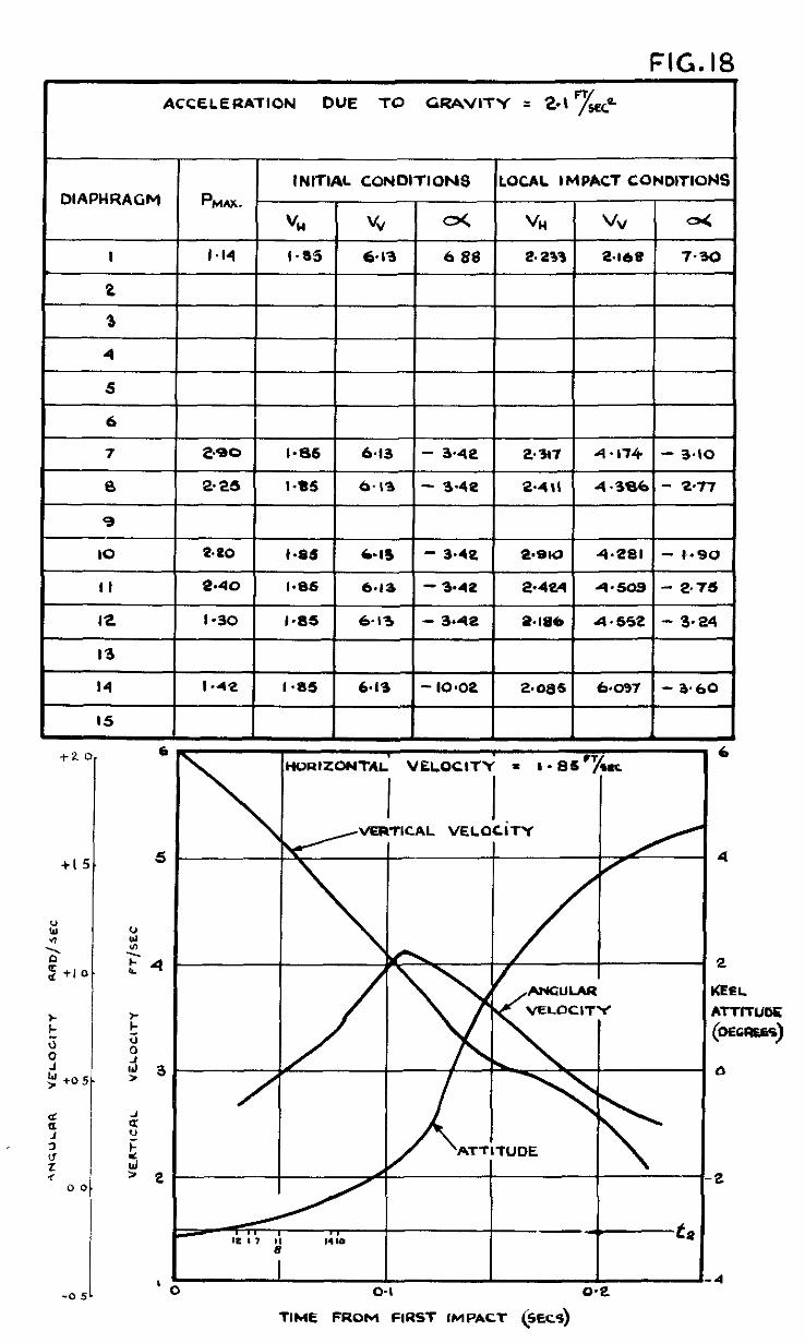
FIG. 18 ACCELERATION DUE TO GRAVITY = 2-l n/,
DlAPHRAGFl PM*&. INITIAL CONDITIONS LOCAL IMPACT CONDITIONS
“I4
I I a I4 I-85 6.13 6 88 2.233
2
3
6 I
7 2.*0 I.85 6-13 - 3.42
I3 2.25 I *a5 6. I3 - 3.4e 2*4\L I I I I I
9
IO Se0 I.BS C-IS - 34e ll*SlQ
II 2.40 I.86 6.1, - 3.42 2.424
I2 I-30 1-W 6-13 - 3.42 2.1&N
I3
I4 I -42 I *a5 6.13 - IO.02 2.085
I5
4.281
4.609
4.552
6.097
ti 6 HVFIIZONTAL VELOCITY = I - 13scT/cIc
I 1 VERTICAL vELocim
I
.
H
c
(
- ,
-:
-a
+I
J ANGULAR VELOCITY
?
‘UDE
b
4 -0
TIME FROM FIRST IMPACT (SSECS)
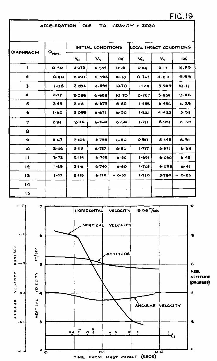
FIG. 19 ACCELERATION ’ DUE TO GRAVITY = ZERO
INITIAL CONDlTWblS LOCAL IHOACT CONDITIONS )IAPHRACM PM.c**.
“I4 VV ti VI4 vv o<
I 0.30 9.072 6.544 16.8 c-64 3-17 15.89
1 0.77 1 2.OSSl 6.5881 IO.70 1 0.787) 3.2521 9.86 1
5 I 2.49 1 2.112 1 6*6731 6.50 1 I.4801 6.5361 b.24 1
6 I I.60 ) 2.039l 6.671 1 6.50 1 I.2Y I 4.4251 5.93 1
7 I 2.91 I 2.116 I 6.7401 6.50 I 1.711 I 5.951 I 6 38 1
8
9 t-i.67 2 IO6 6.739 6.50 0 917 5 648 6.31
IO -2.48 e-112 6.757 6.50 I.717 5a71 6 30
II 3.72 2.114 6.752 6.50 I.691 6.090 6.42
TlME FROM FIRST IMPACT (f++2cS)
- a
- 6
KEEL ATTITUOE
@ECREES)
- 4
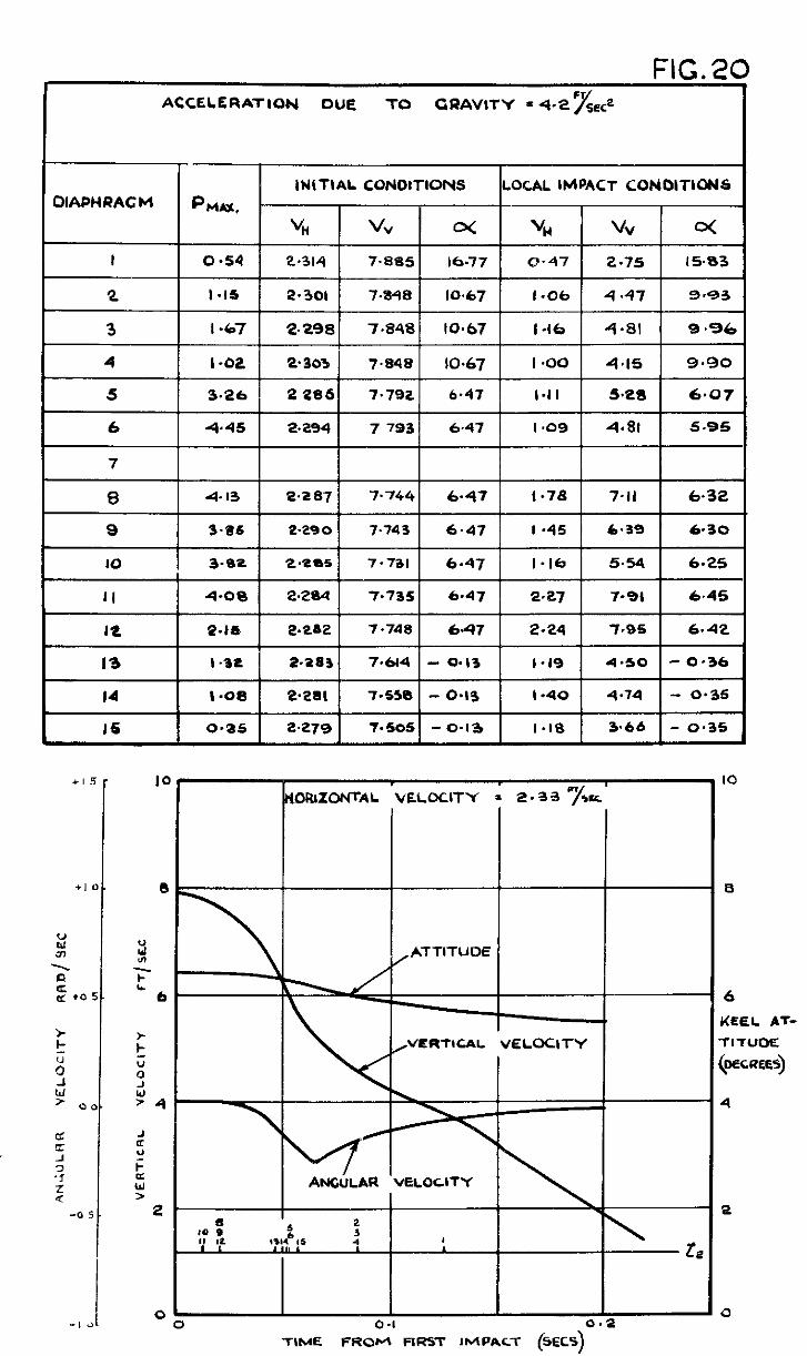
FIG.20 ACCELERATION DUE TO GRAVITY = 4.2 S& Y
~IAPHRAC M
! !
2 2 6 6 6 6
KEEL AT- KEEL AT-
; ; TITUOE TITUOE
; ; 0 0 (MCREES) (MCREES)
: : ‘4 ‘4 4 4
TIME FROM FIRS-I- IMPACT (SECS)
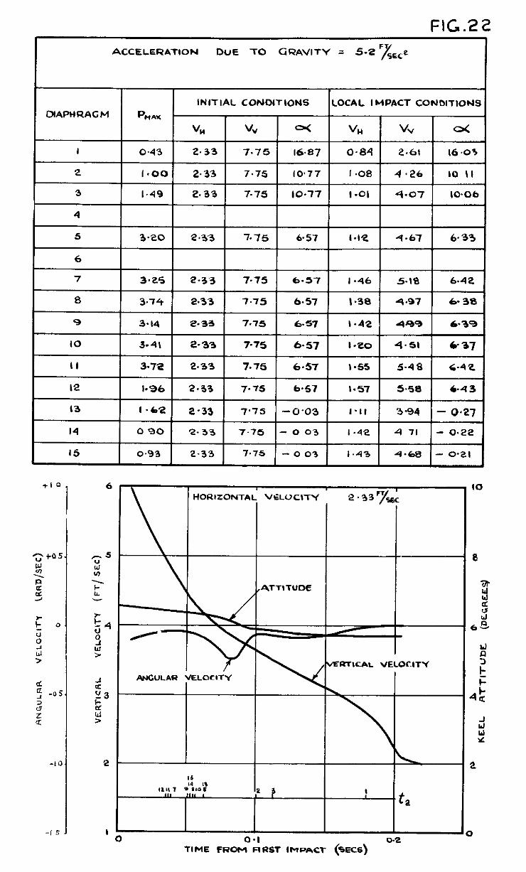
FIG.22
ACCELERATION DUE TO GRAVITY = 5-e ‘J&
INITIAL CONDtTtONS LOCAL IMPACT CONDITIONS
DtAPHRACM
I3 I.62 2-33 7’75 -0.03 I’tt 3-94 - 0.27
14 0 90 2.33 7.75 - 0 03 I .42 4 71 - 0.22
I5 0.93 2-33 7.75 - 0 03 1.43 4.68 - 0.21
HORIZONTAL VELOCITY
MRTICAL VELOCITY
ANCULAR VELOCITY
V~.
-.- TtME FROM F,RST IMPA‘X (%X6)
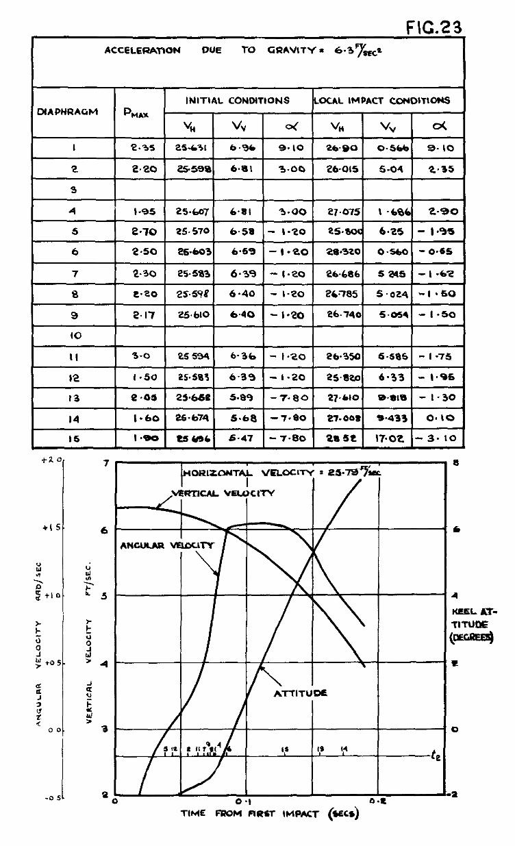
F\C.23_ ACCELERATION DUE TO GRAVITY = 6’3FyoKo
INITIAL CONDITIONS LOCAL IMPACl CONDlTlDNS XAPHRAGM PHAx
“i vv 4 “I4 V” oc
I r.35 25.631 6.96 9. IO 2690 O-566 9. IO
2. t.to 25.598 6.a1 3.00 26-015 5.04 ‘L-35
4 1 1.95 1 25&07( 6.81 1 3.00 1 27.0751 \ -6861 t-90 1
5 2-70 25 510 6-58 - I.20 PS.8oa b-25 - l-95
6 2.50 t?6*603 6.69 -I-20 2S.320 0.560 - 0.65
7 2.30 25.583 6.39 - t-20 26.686 5m5 - I -6.Z
8 2.20 25&?8 6 40 - I-20 X.785 5.024 -I -50
9 2.17 25.610 640 - l-20 26.740 5.054 - I.50
IO
II 1 3-o-~ 1 &q 6.367- I .20 1 26.3501 S.&s 1 - I -75 1
t2 1 l-50 1 25.583 1 6.3% 1 - I-20 1 25Wo1 4.33 1 - 1-95 i
13 4-05 25.668 5.89 -71-80 27.610 em8 - I.30
14 1.60 26,674 5.6a -7.80 ~l-OO8 5.433 0.10
16 I *Qo t6HC 6.47 - ‘I.80 ta 6t 17.02 - 3. IO
* ., b.L
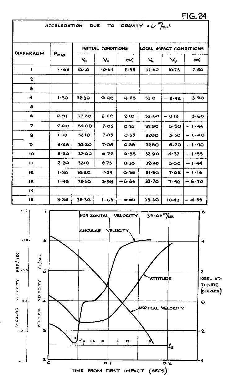
ACCELERATIW DUE TO GRAVITY * 2.1
INITIAL CONDITIONS LOCAL IMPACT CONOITIONS DIAPc(RAGbl %A%
vi4 4 o< VI4 % d
I I .68 32.10 10.34 8.85 31.60 IO.73 7.50
2
3
I 4 1 1.30 1 32.30 1 9.42 1 4.85 1 so I- a.& 3.90 1
1 6 1 0.97 1 32-20 / 8.22 1 &IO 1 33.60 I- 0.19 1 3-60 1
7 2.00 W&O0 7.05 0.35 32 90 5.50 - 144
8 I.10 32 IO 7.05 0.35 32.90 5.50 - I .40
9 3.25 32.20 7.05 0.35 32aa 5.20 - I *40
10 2.20 32.00 6-72 0.35 32.90 4.37 - 1.33
II 2.20 32dO 6.73 0.35 32.80 5.50 - I.44
I
I I I I 1 I I
I2 I.80 32.20 7.34 0.35 31.90 7.08 - I.15
I3 I.45 32.30 S-98 -6.65 33.70 7.40 - 6-70
I4
IS 3.85 32.30 I.63 - 6.65 33.30 IO.43 - 4.55
15
1, 0 !
7
6
t
4
TIME FROM FIRST IMPACT (kECS)
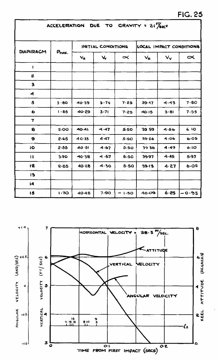
FIG. 25
INITIAL CONDITIONS LOCAL IMPACT CONOll-lONQ DlAPURACM 64w.
“Ii % H %I VV o(
I
I?
3
4
1 3.80 I 4039 I 3.74 I 7.25 1 39-47 1 4-43 1 7.80
6 I.85 40.29 3.71 3.81 7.55
I
7.25
7
8 2.00( 40.41 14.47 1 5.501 39591 4.561 610 1
I 9 I 2.65 [ 40.33 1 447 5.50 ) 35.26 1 4.06 1 6.05 1
IQ 2.85 40.28 4.30 5.50 39.13 4.27 6.05
I3
I4
13
I4
I5 I -70 4048 7.90 - I.50 40.09 6.25 -0.93 I I5 I -70 40.48 7.90 - I.50 40.09 6.25 -0.93
IO 2*53 40.51 4.b7 5.50 39 36 4.49 6.10
II 3-90 40-38 4.67 5.50 39-97 4.45 5.97
+I 7
t=IG “16.
ACCELERATION DlK TO GRAVITY =
f WORlZONT4L VKOCgTY : 3:
.h
‘/,
96 FT/C
-
a UnrxlT’ I
ANGUUI
%
-0 0.1
tlhit FROM FIRST IMPACT (5-S)
o-2
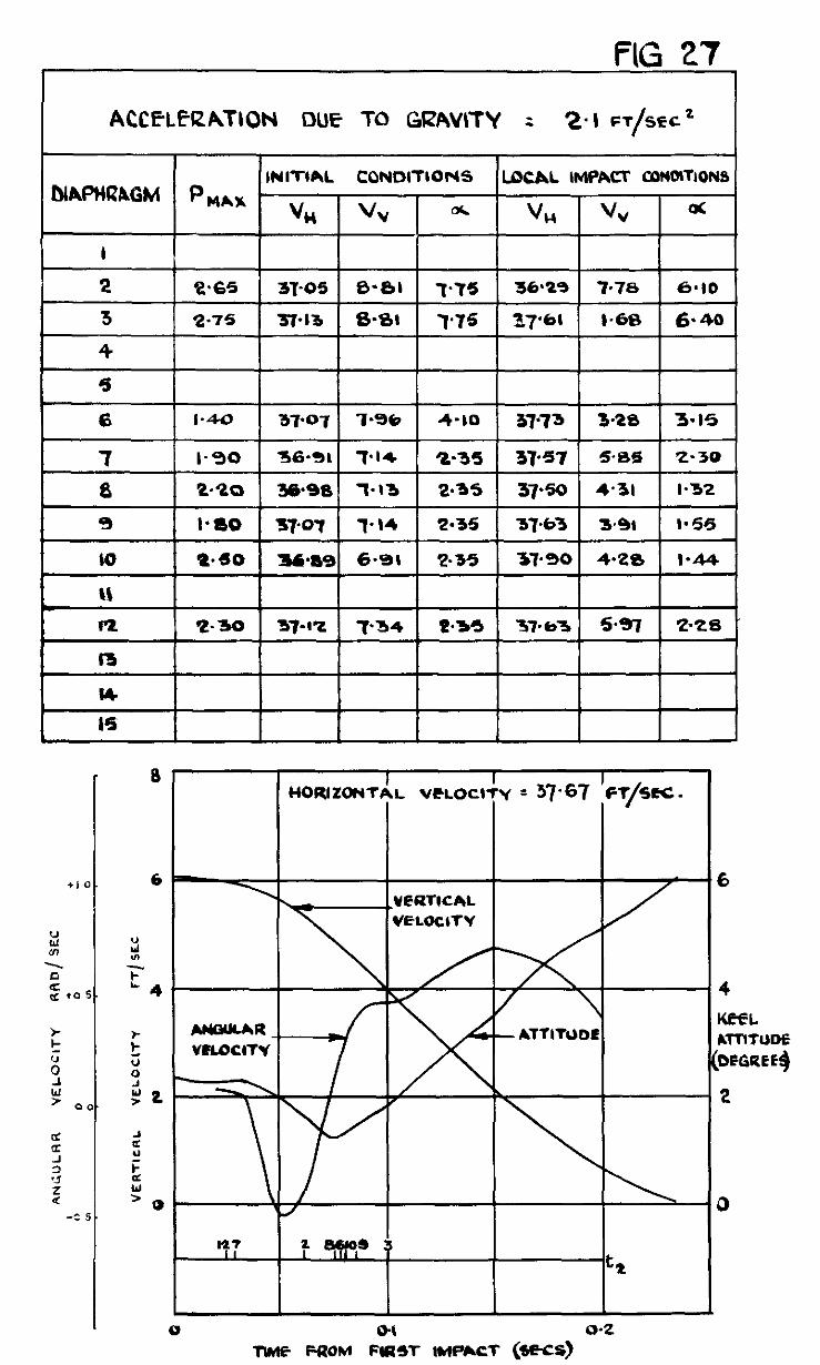
FIG 27
6
4 llhlE FROM &T IMPhCT (WCS)
o-2
6
ACCELERATION DUE TO GRAVITY = 2. I FT@2
4
-1.5
2
I
0 0
n
TlME FROM FIRST IMPACT (SECS.)
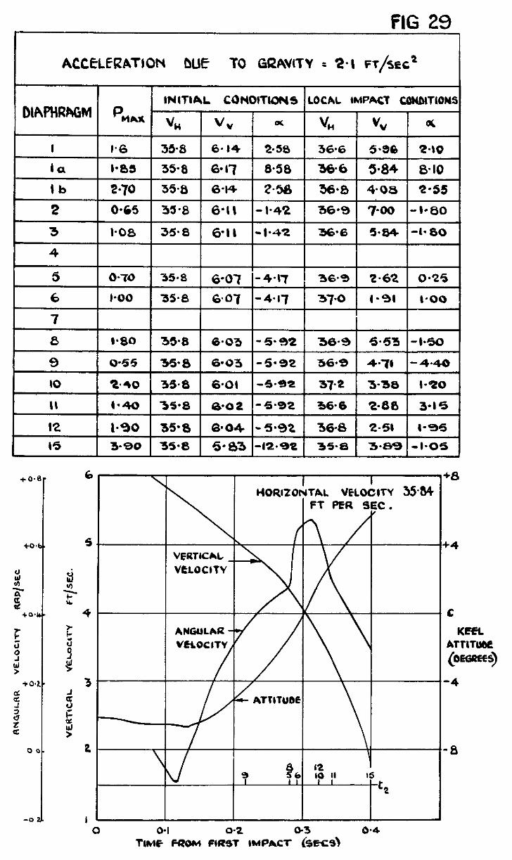
FIG 29 I
ACC&.ERATION DLE TO GRAVtTY = 2. \ FT/ST: c2 I
t fllAPHRl%GN INITIAL CONOtTlOtUS LOCAL (MPACT CWDlTlONS
I -.. . . . ..-. .-.. I PM&&
vn vv a V” I “” 1 6
t 1.6 35.8 6.44 2-58 36.6 5.36 2.40
la I*85 3!98 60 17 8.58 36-6 5.84 &IO
lb 2.70 35.8 6-14 Z-58 36.8 4-08 2.55
5 O-70 -55*8 6-07 i-4-R 36.9 2.62 O-25
1 6
I 7
l-00 35.6 6.07 -4.17 37.0 I-91 I-00 I I
9 o-55 35-8 6.03 -5-92 36.9 4-7) - 4.40
10 2.40 35.0 6.OI -5.92 37.2 S-36 l-20
II 1.40 35-8 e-02 - 5.92 366 ‘L-80 3.15
I2 I.90 35.0 6*04 -5.92 36.8 2-51 l-45
I5 3.90 35.8 5.03 -12.92 35.8 3.89 -1-05
2
/ I
\ /
,
FT f’ER SEC. FT f’ER SEC.
\ \ 12 12 IO II IO II I5 I5
-----I -----I
c2 c2
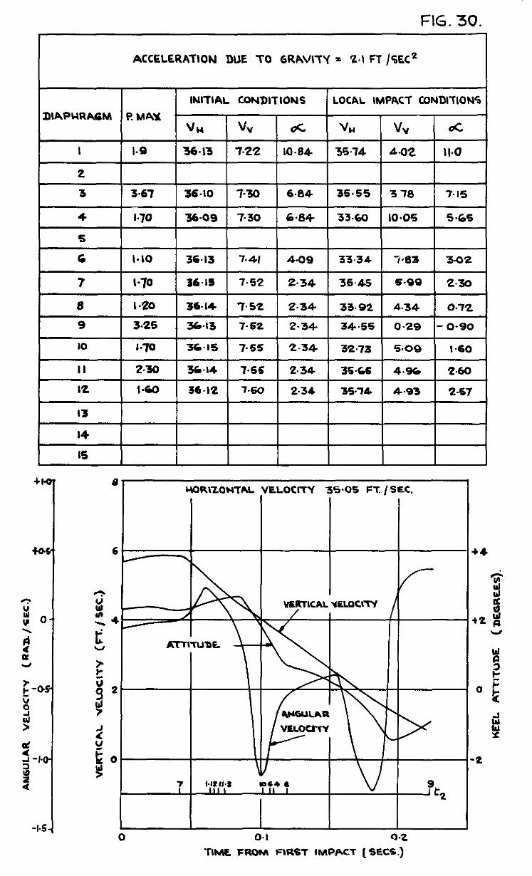
FIG. 30.
ACCELERATION DUE TO GRAVITY = ‘2.1 FT /SEC2
!I a 4
-1.5
VELOCITY 35.05 FT. i SEC.
0.1 9.2
TIME FROM FIRST IMPACT [ SECS.)
l=IG. 31. ACCIZLERIUWN DUE TO GRAVITY = Z&R0
,6 V \ KWL
/irTlflJDC (DWEES)
F -lG 32 ACCELERATION DUE TD GRAVITY = ZEQO
I I 1 INITIAL ~o~~OITIONS 1 LOCAL IMPACT COND~IO~ OIAPWRAGM P,
Vi4 VV & VI4 VV d
I / / / / / / /
2 /// // / /
I 6 1 I,25 1 37.65
1 I / I / I/
I 15 11% 1 3732 6 47 1 3.45 1 3615
6
a.47 I IO*45 36.47
8.69 1 10.45 1 3656
9
ERTlcAL VELOCITY ERTlcAL VELOCITY
9
KEEL ATTITUDE (DEGRWS)
7
KEEL ATTITUDE (DEGRWS)
7
II
RG.33. ACC%LtRATION DUE TO GRAVITY = 4 2. &EC2
IWTIN. CONDITIONS llocAL IMPACT cownows
2 ///ii// 3 1 / / / / / /
4 j////j/
5 / / / / / / /
I I2 I 2.20
I3 / kk 14 /
IS /
6 \
1’76 7 IO 52b I .75
499 I.90
$
225 4-60
4.30 2.35 4.38 ta4
$93 I*80 / / EEI / / / /
6
FIG. 34 ACCELERATION DUE l-0 GR4VIT-Y = 4’2 Fd%”
DAPf-QbcaM Pw INIl-IAL CoNDlTiONS
\IM I vv I Q(
6
40~ 1 4~ I- 0% 1
\ - 0.0
_ -20
I 7 Y II IL 8 613 lo9 I 4 I I5 I 7 II IL 8 613 lo9 4 I5 t-2
FIG. ACCkLEOATION ()UE TD GRAVITY = 6 SFTkC’
INITIAL CONDITIONS LOCAL IMPACT CON017iON5 DIAPIiRAGM PN\W
VH +Jv c% vu \Iv m
I / / / / / / /
2 / / / / / / /
3 / / / / / 1 /
4 / / f / / / /
5 / /
6 I.30 40.4
/
533
5-76
576
5.76 4.40 40% 54q 4.73
4.40 3902 493 6.45
4.40 41.0 4*04 1 5.70
4.40 40.4 3.66 6.14
-t6 40-7 7.10 -0.86
35.
RTICAL VEUUITY
/ 0
TIME FROM &T IMPACT (SECS) o-2
FIG. 36. ACCE-LERKTION DUE To GRAVlT’f = 64 !=TkC’
I 7 I/ I a I’LL&
/+-l-Et ta
113 I240
/
3843
3&3l
3853
38.38
38 27
38.34
/
/
/ I / /
/ / 3.18 7.30
33 448 5.55 / / 3.92 4 75
442 1 4d5 1 9’98 -392 24 / /
/ r’
,
HORIZONTAL VELOCI HORIZONTAL VELOCITY’
FIG. 37.
0 0 0 0 0.1 0.1
TIME FROM FIRST IMPACT (SECSJ TIME FROM FIRST IMPACT (SECSJ
FIG. 38.
ACCELERATION DUE TO GRAVITY * %I FT /SEC?
DAMPER 5
INITIAL CONDI7ONS LOCAL IMPACT CONDITIONS DIAPHRAGM P MA%.
vn V” oc vn % QC,
, -------
I 2 I-
4 I 5 90
6 3.7
I 7 I-
32.2
32 2
5.69 ! 6.75
5 -70 6.75 I
31.0
31-4
2.32
7.42
I 8 1 IO.4 1 32.2 1 S-85 1 6.76 1 31.2 1 3.23 1 7.02 1
I 9 1 6 5 1 i2 2 1 5.86 1 6.75 1 31.8 1 5.00 1 6.72 1
IO 17-O 32.2 5 91 6.75 31.7 4.68 6.92
II 19 5 32.2 5.91 6.75 31.2 3.13 7.03
I2 ----- ~ -
I3 -----__-
,4 -------
I5 __---~--
0.1 0.2 TIME FROM FIRST IMPACT (SEC3
F IG. 39.
ACCELERATION DUE TO GRAVITY - SIFT /SEC!
DAMPEP $.
INITIAL CONDlTION6 DlAPCIRAGM PMAX’
VU VY
LOCAL IMPACT CONDITIONS
VU VY oc I 2 -
El- 3 -
4 --
5 4.8 33.5
I .60
-I--- -l
6
TICAL VELQCiTY
4
2 / A
/ /
0. /
5 2 II 810 I3 I II
I
0.1 C Tlhk FROM FIRST IMPACT (SEC3
0 0
FIC.40. ACCELERATION DUE To GRAVITY - 2+~/seC?
DAMPER %.
INITIAL CONDITIONS LOCAL IMPACT CONDITIONS DIAPHRAGM F! MAY.
VI4 VV’ lot VI-I VV I a
I -- --
I 2 -- l I I I I 3 -- l I I ,
I 5 IQ.7 1 33.75 1 6.1 16.7 1 33 06 1 iSO9 1 6.83
6 -- l I I I
7 -- ! ! ! !
6 I I.0 33.75 6.1 6.7 33 77 5.18 6.73
9 --
lo IS5 33.75 6.1 6.7 33- I3 4.05 6.80
I II 1 9-7 1 33.75 1 c.1 16.7 1 32.91 1 3.76 1 6.77
I2 -- - -
I3 I.3 3375 6.1 0-I 334% 3.12 0.43
I4 --
15 --
HORIZONT~
VERTICAL VELOC VERTICAL VELOC \’
TIME FROM FIRST IMPACT (SEC4
i VELOCITY -
I
33.75 jt./sec.
I
r-f r-f
ATTITUDE ATTITUDE
/ /
-AN6lJLAR VELOCITY -AN6lJLAR VELOCITY
ACCELERATION ME TO GRAVITY = m jt/SeC’
lAMPER 3.
5.60 74 33.0 2.35 7.8
540 I ‘1.6 1 33.0 1 0.67 1 0.02
-- --
-- --
5-60 7.6 33.5 3.86 785
S&O 7-c 1 34-3 1 6.36 7.64 I I I 1
I 14 I-I- -I- I I- I 5.60 1.0 33.5 3.06 I.25
HOR lZONTAL VELOCITY - 34 ft.&c
0
13 13 1015 1015 5 5 6 6 I I I I I I
42 42
0-I 0-I 0.2 0.2 TIME FROM FIRST IMPACT (SECG
FlG.42. ACCELERAT\ON DUE TO GRAVITY = 21ft/Sd
DAMPER f
INITIAL COND\T\ONS /LOCAL IMPACT CONDITIONS ] DIAPl-tRAGM f? MA%.
1 2.1
u, V” 52 vn vv oc
33.)1 5.5 7.0 32.92 5 0 7.0
33.11 5.5 2.2 33.93 2.34 2.5
33.11 5.5 2.2 32 94 5.1 2.2 l-G--k 4 60 33.11 5.5 2.2 33 84 2.29 2 7
5 I0 33 II 5.5 -32 32 93 S-05 - 3.2
6 I II 33.ll 1 ‘5.5 l-3.2 1 33.55 1 3 92 l-3-1 1
I ~5 r- -l-l-l-l-l-l
l-G--k 33.11 5.5 -3.2 33.95
33.11 I 5.5 I- 3.2 1 34 02
l I6 -
- 33.1 I ft./set HORCZOt.lTAL VELOC\T
\ .ATT\TlJDE
_ 0.2 TlME FROM FIRST IMPACT (SE@
ACtZIELERATK)U WE -i-o GRAVITY = 2-l FT/SLc.
DAMPER %. FIG.43.
I I I INITIAL coNoITlw5 I LOCAL IMPACT coNcmd
I 5.0 33.6 8.13 7-3 3‘%0 6.9 7-5
2 75 a3.5 7.83 2.5 33.5 7.99 2-e
KEEL z Arnwuf
bEGREE3)
DIAPl4RAGH
I
la
lb
2
3
4
5
0
?
a
9
IO
II
I2
IS
ACCELERATION DUE TO GRAVITY t.1 FT/SEC*
DAMPEe 0
HORIZONZCIL VCLOCW I 32.13 n//rrc
FIG.44.
TIME FROM FIRST IMPACT (SW)
FIG 45.
VraTdL veknc4t
6
ACCELERATION DUE To GRWITY s 2 I FT/~
DANPER ‘13
0
LNITIAL VELOCITY LOCAL IMPACT CONBITIONS DIAPHRAGM p flAl
% vv o( “tl VV oc
I
lb 1 i-35 1 33.22 ( 1 8-60 1 33.61 ( 349 1 9.2
2 6.7 35.54 ( 619 1 -2.6
3 1 80 1 C-7 ( -2-60 1 33.63 1 5.57 1 -2.4
4 6.7 1 -2.60 1 5.41 I-2.25
91 I
I2 I I I I I 13
14
15
,
, .
5 1
0.
I
c ” :: z-
4
; z 0
i >
2-
- 7
, ,‘. .o
‘r v22Tl CAL VELOCITY
ANGULhR
/
/
0
II
-2 \ KEEL ATTITUDt (DLrmS) -4
-I -6
‘4
/ -8
TIME FROM F1RS-t IWCACT (SEC’S)
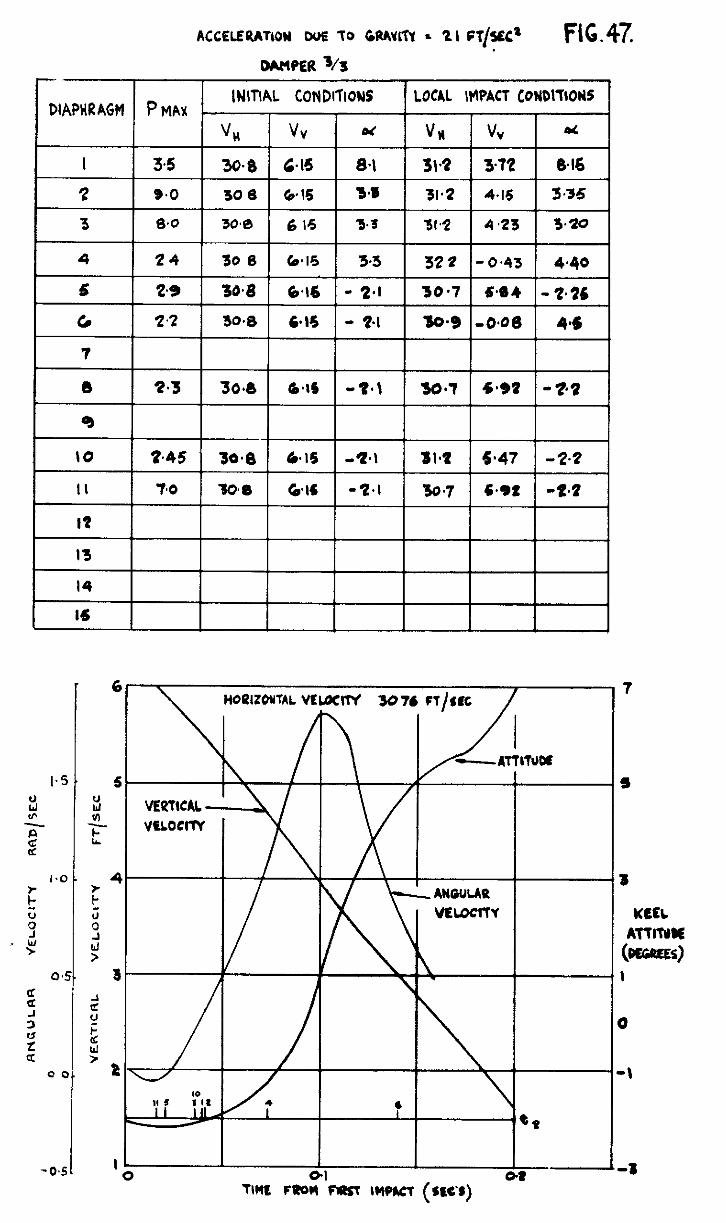
i.
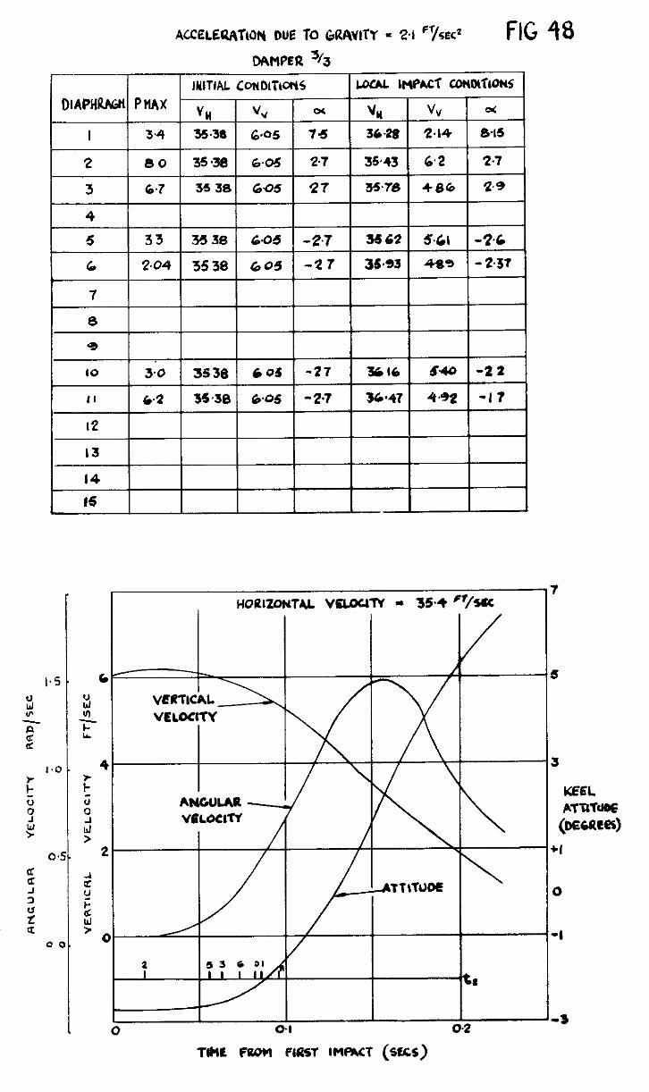
ACCELEUATIO~ DUE TO GRWITY = 24 fT/s~cz FIG 48
HOUlZOWhL VUOUlV - 354 %Sc
/
I - 0-l
ATTITWE
\
\
3
KEEL ATtITUfS
. +I
0
-I
-3
TIME lw.m PlfzsT IMmcT (sm)
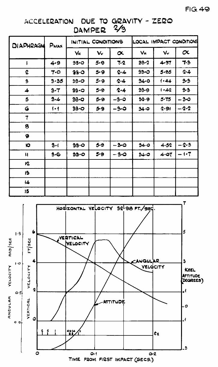
FIG 49
42ZXXLEOATION DUE TO GQAVITY - ZERO DAMPER */3
TIME FROM FIRST IMPACT (SECS.)
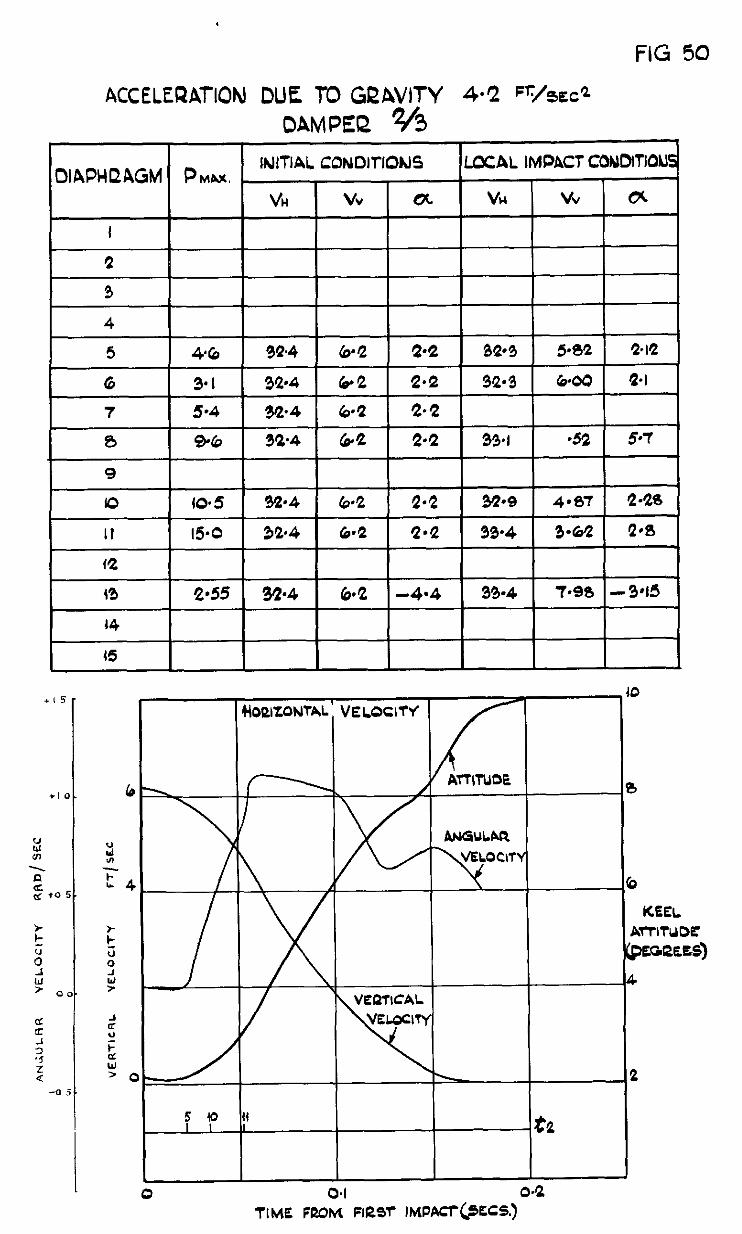
FIG 50
ACCELERAl-ION DUE r0 GQAVITY 4.2 =,/zmz” OAMPEQ %
--=-HA- L 0.1
TitdE FROM Flrar rMPACT@SCS.)
FIG.
ACCELECZATION DUE TO GQAVITY 4-Z Fr/ix&
1
1
0 -+
51
7
5
3
KEEL 4rnTUDE paREE9)
1
0
4
3
ACCELEQLITION DUE To GRAVITY 6.3 FT/s~c? OAMPEQ %
a
1
tiCEEL ATTITUDE (OEGREES)
1
FIG. 53
ACCELEQATION DUE To Gi2AVll-Y G-3 “t&c2 DAMPEl2 e23.
, oraPHeaGM pMhx INITIAL CONDITION4 I
LOCAL IMPACT CONOlTlON5 I I
idOt2lZONTAL VELOCITY
I
0 . 04. TIME F&iii FILM- lMPAC+@ECS.)
0
b
KEEL ATTITUDE (CEGQEES)
4
FIG.54
LOG K3
I I I I
VARIATION OF K3 WITH VN FiX RAXS OF DESCENT of 4736 '?&c
VARIATION OF Ke WITH %I FOR RATES Of DESCEMT OF 410 6 %c. (klNTs FROM 1 PO$mON to)
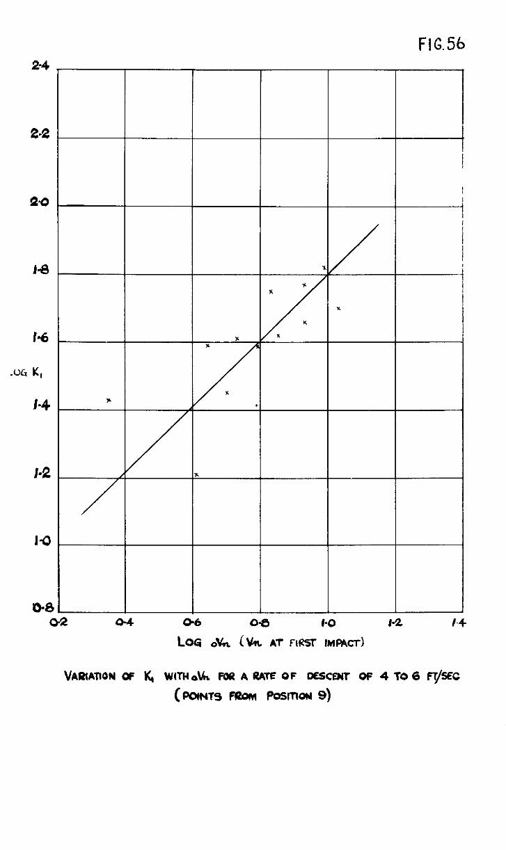
--+----I
VARIATION OF X, WITH o\h FOU A UATE OF oescmir OF 4 To 6 ~/SEC
(twws 1320~ Posmorr 9)
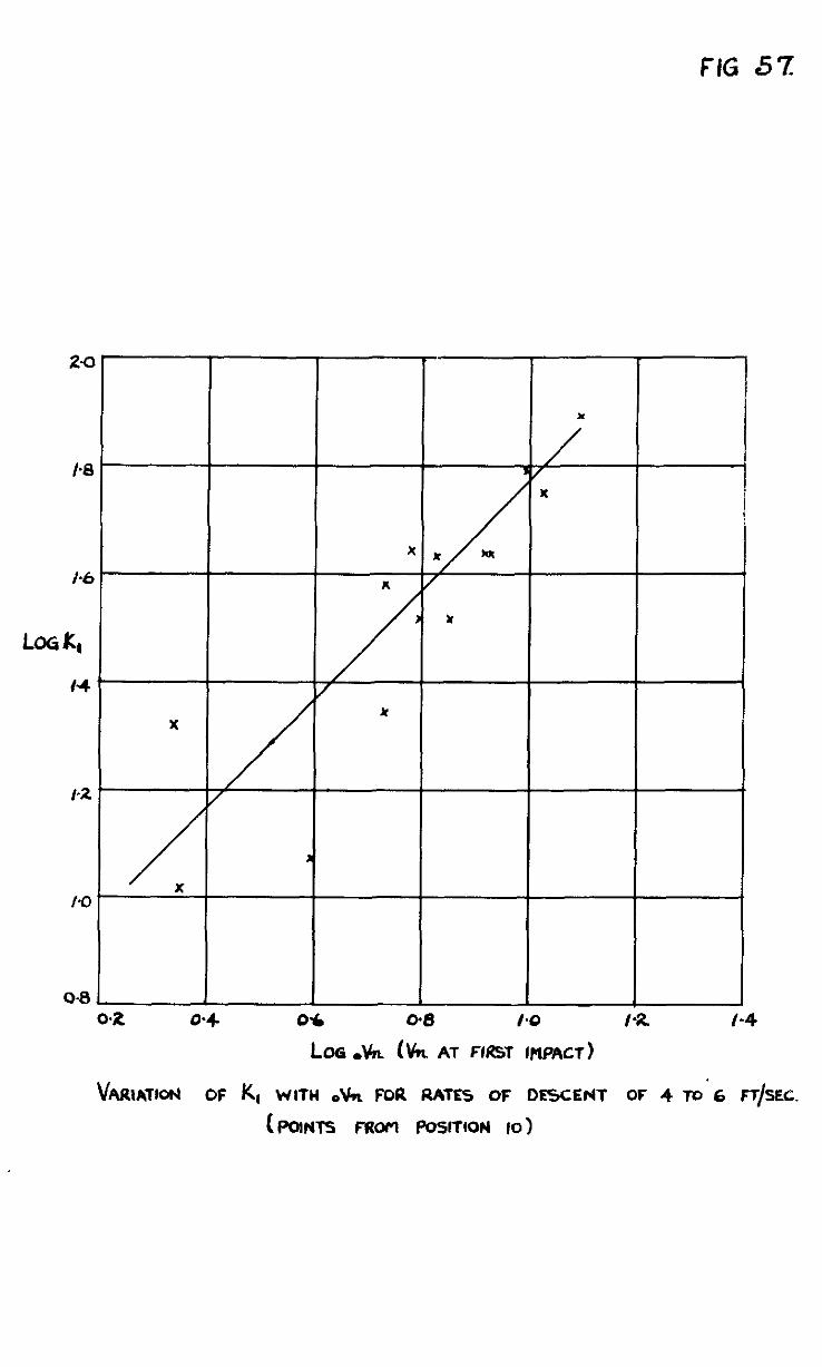
FIG 57
LO6 .k &n AT FlRST INPACT)
hRlATfo(rl OF K, WITH 0% FOR RATE5 OF DFSCEr41 OF 4 TO’6 FT/SEC.
(POINTS Faom PosrrloN IO)
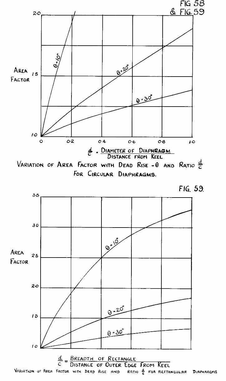
FIG 58 2.0 I & FIG.59
V I
AREA FACTOR
1s
I-O 0 OQ 04 0.6 O-8 1-O
& - DIAMETER OF DIAPHRAGM DISTANCE FROM KEEL
VARIATION of AREA fAcToR wrw DEAD f&x -8 AND ~TIO $
ha GRCULAR DIAPIGZAGMS.
FIG. 59.
AREA F ACTOR
30
25
2-a
IS
10
d BREADTH 0F RECTANGLE c' DISTANLE OF OUTER EDGE fRoM KEEL
URINATION JF RRER FRCTQR WIN DERD RISE F\~JD RRTIO $ FOR RECTRNGULRR DIRPHRRGMS
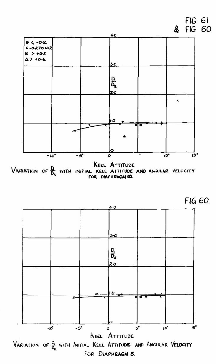
FIG 61 $ FIG 60
40
0 < -0-2 x -0-2TO 402 a > +0-x 4? +a-&
5-O
a
0,
2.0
x
A
0 & -10’ - s 0 ., IO’ IS’
V %i KEEL ATTITUDE
ARlATloN OF WlTH lNfTlAL KEEL ATTITUDE AND ANGULAR VELOCITY
FOR DlAPHRAGM (0.
FIG 60
0 0
-Id -5” 0 5’ Id 6’
V' KEEL ~TTITUOE
~RIATION OF D 4 WITH INITIAL KEEL ATTITUDE AND ANGULAR bbccr~ z
f-OR ~lAPHfU&l 5.
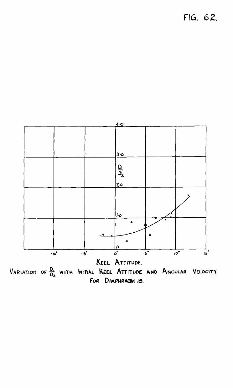
fIG. 62.
4.0 4.0
3.0 3.0
2 D D 2 0, 0,
20 20
-Id - 5’ 0’ 5’ 10. (5’
KEEL ATTITUM.
v AR~ATION OF -$ WITH INITIAL KEEL ATTITLKE ANO ANGULAR VELOC\
FOR D~APHPAGM 15.
0 0
-Id - 5’ 0’ 5’ 10. (5’
KEEL ATTITUM.
v AR~ATION OF -$ WITH INITIAL KEEL ATTITLKE ANO ANGULAR VELOC\
FOR D~APHPAGM 15. r-f
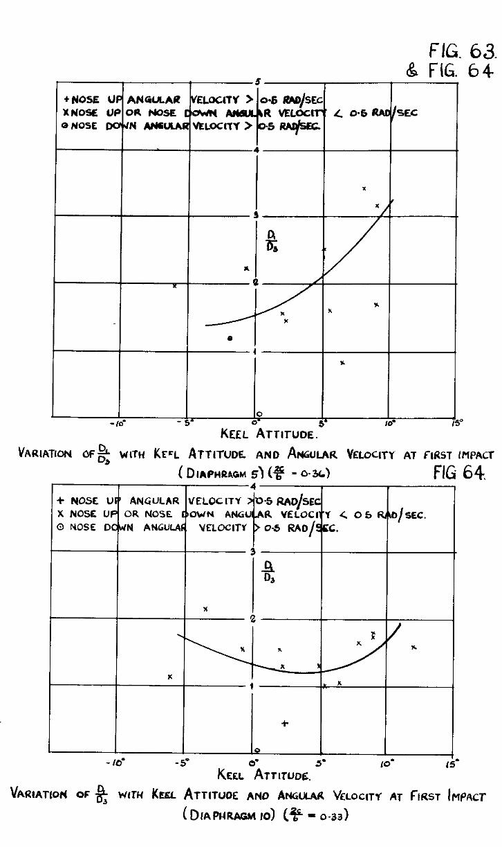
FIG. 63. & FIG. 64
- Id - 5’
VARIATION of2 WITH KECL ATTITUDE AND ANGULAR VELOCITY AT FIRST IMPACT
( DIAPHRAGM s\ (3 - 0.3~1 FIG 64 4 + NOSE UF’ ANGULAR VELOCITY D-5 RAC/SEC
X NOSE UP OR NOSE DOWN ANGU
k
A YELOCI-‘Y ( 05 fQ4t1 / SEC. 0 NOSE DOWN ANGULAC VELOCITY O-5 RAO/SCC.
3
8
x ‘2
. x
x : . r
+
0 - IO’ -5’ 5- IO’ 15.
%atATLoP( OF % wfrti KEEL ATTITUOE ANO ANGULW VELOCITY AT FIRST tr~f~cr
( DIAPI-MGM IO) t% - o-33)
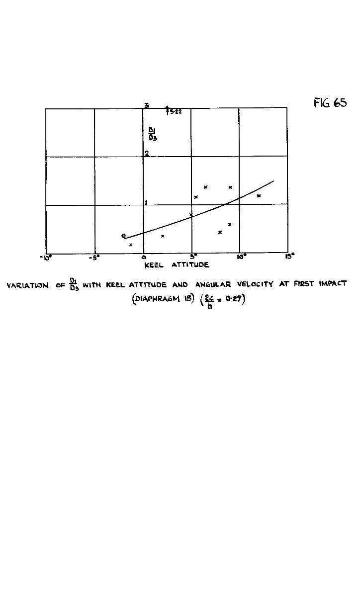
5’
FIG
VARIATION OF F3 WITH KEEL ATTITUDE AU0 4NbULAR VELOCITY At FIRST IMtifl
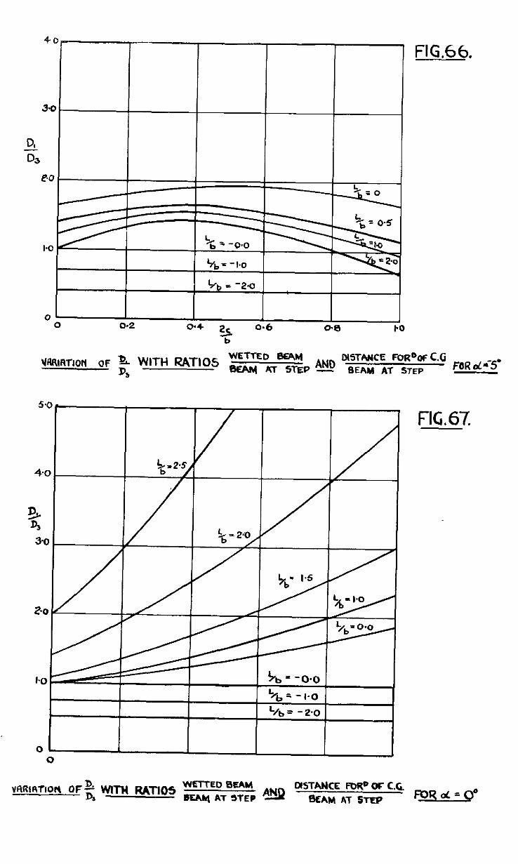
5.0 .
+0
3 %
3.0
2-o
%=-O-0
‘/b = - I.0
L/b = - 2.0
01 I I 0
FIG. 67.
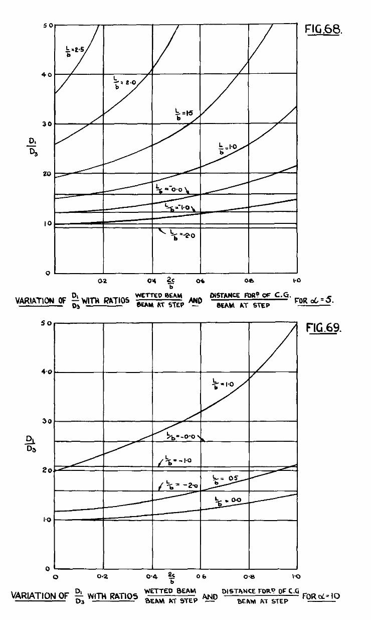
20
IO
m 0
0.2 0’4 2c T
06 00 I.0
==rl== VARlATlON OF & WiTI RATIOS
DISTA?KE FIX? o!= C.G.
BUM AT STEP FOR 06’5.
I I 0
VARIATION OF
06 0’0 I’0
DISTANCE FOR’? OF C.G
BEAM AT STEP FORd= IO
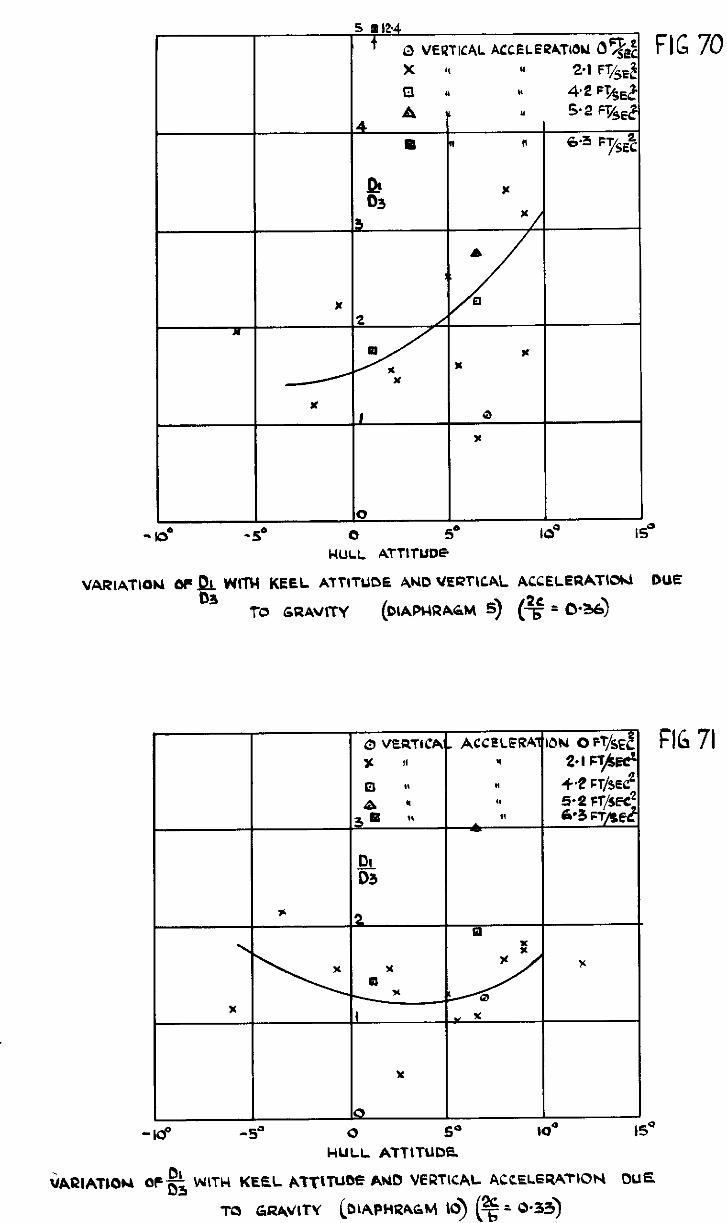
x
0
-loo -5” 0 5” IO’ IS” HULL ATTITUDE
VARIATIQU oF f!& WITH KEEL ATTITUDE AND UERTICAL ACCELERATIW DUE
TO GRAVITY
9 D3
x
-18 -5” 0 ii- IO- IS’
HULL ATTITUDE
FlG 71
TO GRAVITY (DLAPHRAGM 10) (% = O-33)
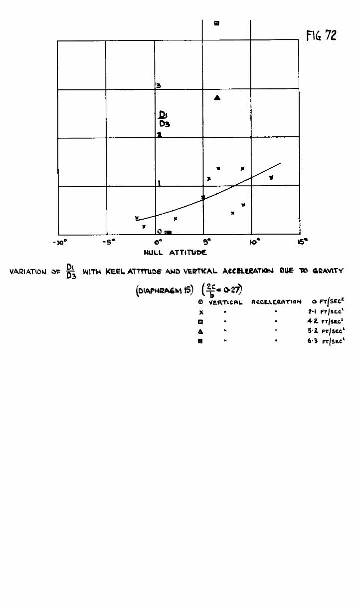
- IO0
VARIATIOU OF F3
FlG 72
-5. 0” 5- lo- IS‘
MULL ATTl’NM1
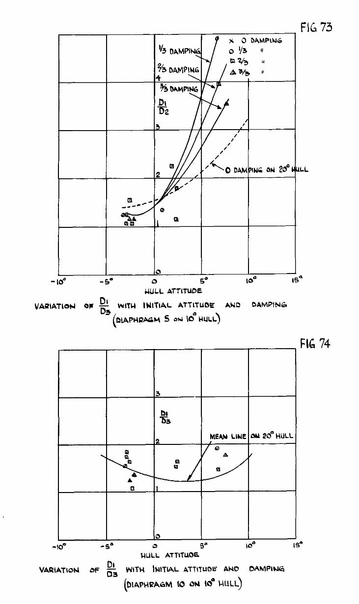
UULL ATTITUDE
01 VAUIATlON OC -3 WITU IUITIAL ATTITUOE AND OAMPlNG
(DIAPHRAGM s OM 6 HULL)
FIG 74
3
2 MEAN LlUE ti 28 HULL ,
0 . A /
tf
A \ u I
40” -5” l&ILL ATTITUOE
DI VAaIATlohl at= c3 WTW hIAL ATTITUDE AH0 DAMPLUG
(b\~~ktRbhM 10 ou lo” MULL)
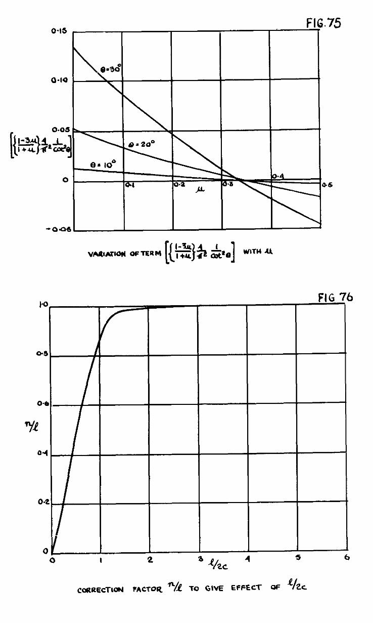
FIG : 6
I
I 2 5 P/ 4 t ,
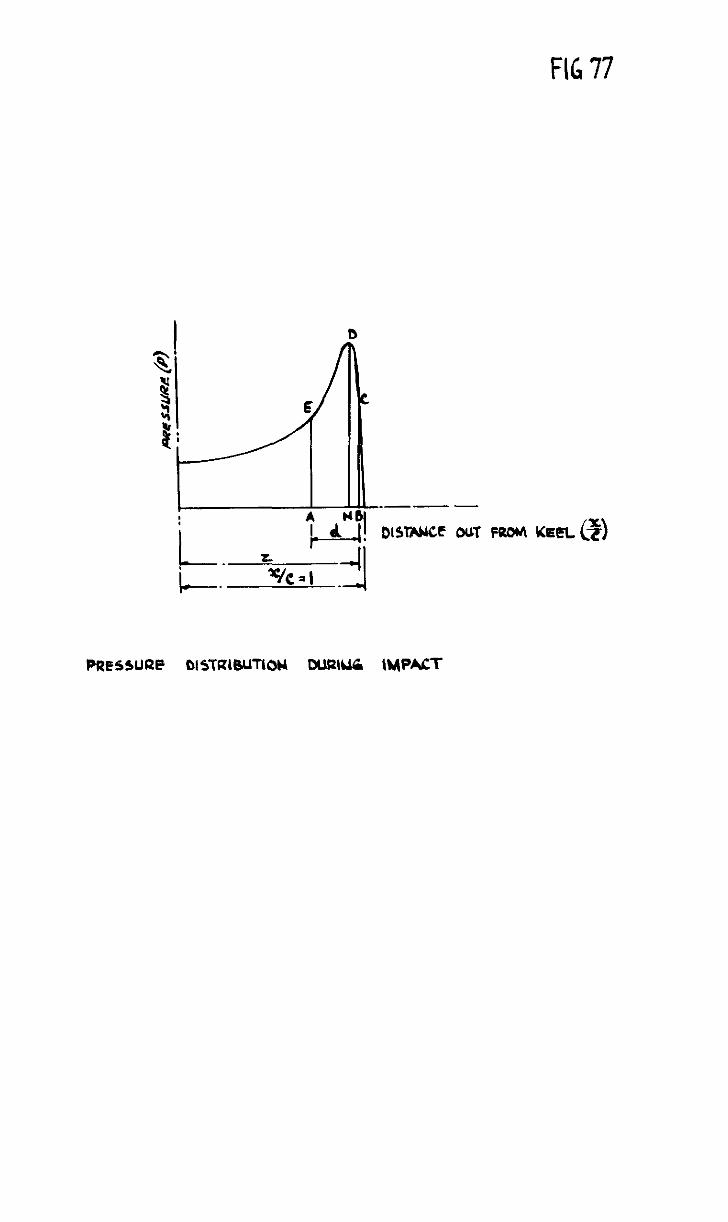
FIG 77
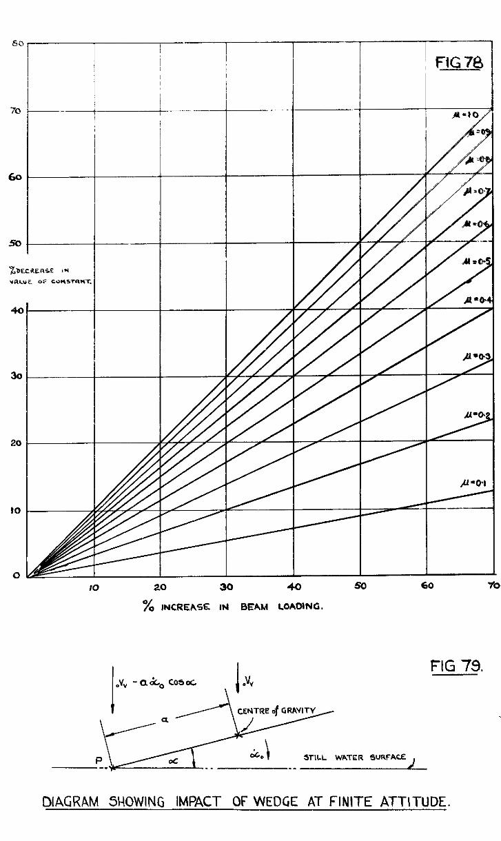
40
30
20
?O
0
I I
---I---
--t-
IO 20 30 40 50 60
% INCREASE IM BEAM LOADING.
STILL WATER SURFACE
FIG 79.
DIAGRAM SHOWING IMPACT OF WEDGE AT FINITE ATTITUDE.
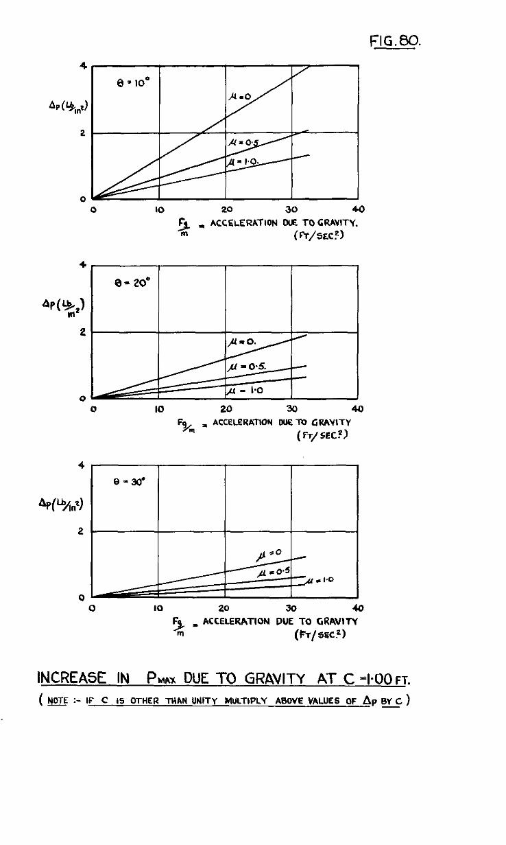
FIG.80.
0 IO 20 30 40
5- ACCELERATION ME TO GRAVITY.
Ill (R/5&)
0 IO 20 30 40
‘tkq = ACCfLERAlION DUE TO GRAWTY
(FT/SEC?)
0 IO 20 30 40
ACCELERATION DUE TO GRAVITY
(FT/src.z)
INCREASE IN PIMX DUE TO GRAVITY AT C =I-00~~.
( E :- IF C IS OTHER THAN WITY MULTIPLY ABOVE VALUES OF Ap BY C )
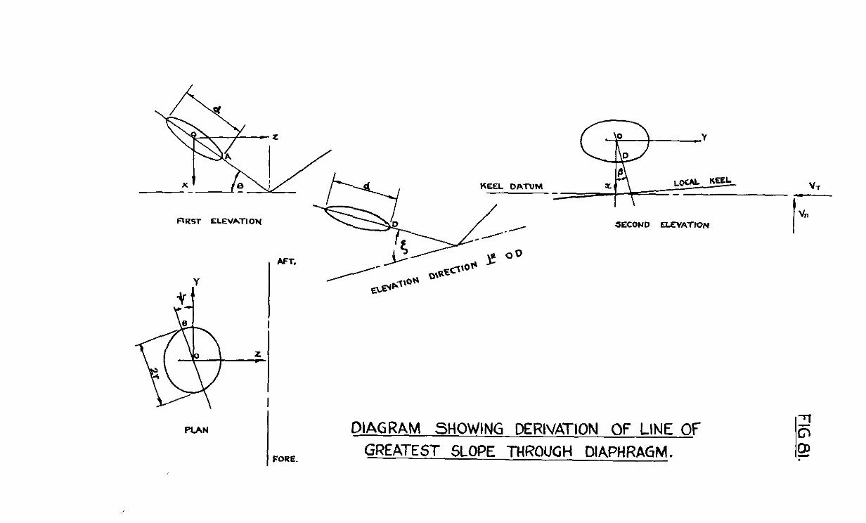
--- I Y
nl2s-r KLEVATION
, AFT.
SECONO CLEVATtON
DIAGRAM SHOWING DERIVATION OF LINE OF
GREATEST SLOPE TClROUGH DIAPHRAGM.
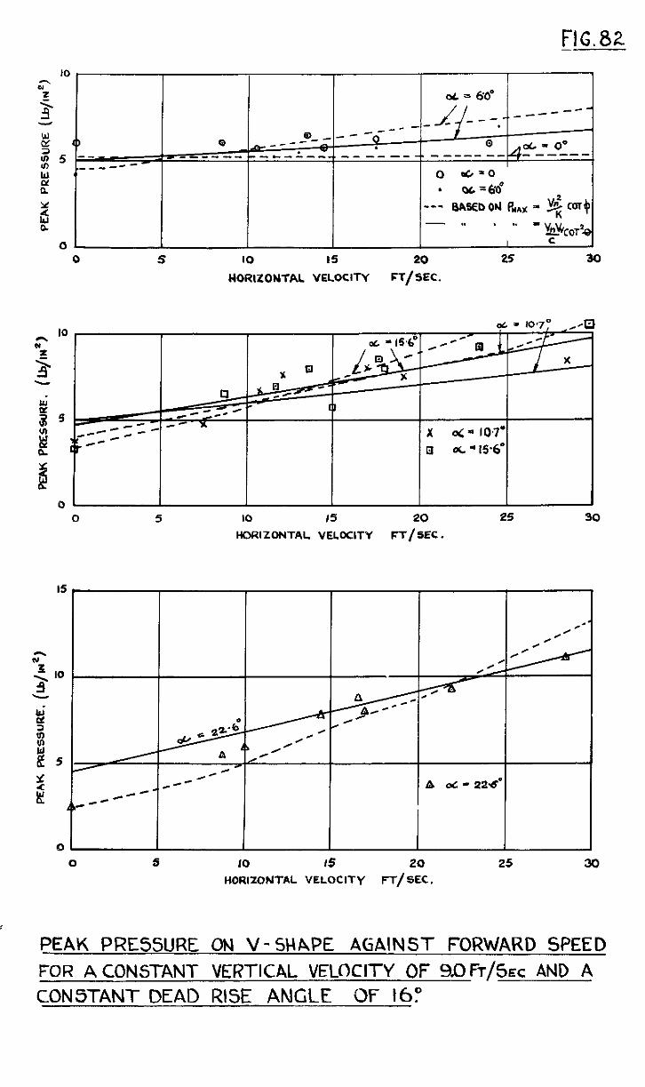
FtG.82
3 0 0 _--- Se,-- ̂ -0--- t Q - Is 5
= ,--------c-l ---.---- ----------- - d ----- 00
c s--- --- I
0 dr=o
L? . OL-M
2 --- BASEDON P*rg = COT+ 4: - I. . * = $
b!$OT2, 01 I I I I I c J
0 5 IO 15 20 25 30
WORlZONTAL VELOCITY FT/SEC.
0 ’ I 1 I I I I
0 5 IO 15 20 25 30
HORIZOUTAL VELOCITY FT/SEC.
ir
:
A d - 224
0 s IO I5 20 25 30
HORIZONTAL VELOCITY FT/SEC.
PEAK PRESSURE ON V-SHAPE AGAINST FORWARD SPEED FOR A CONSTANT VERTICAL VELOCITY OF 90 FT/SEC AND A CON5TANT DEAD RISE ANGLE OF 16:
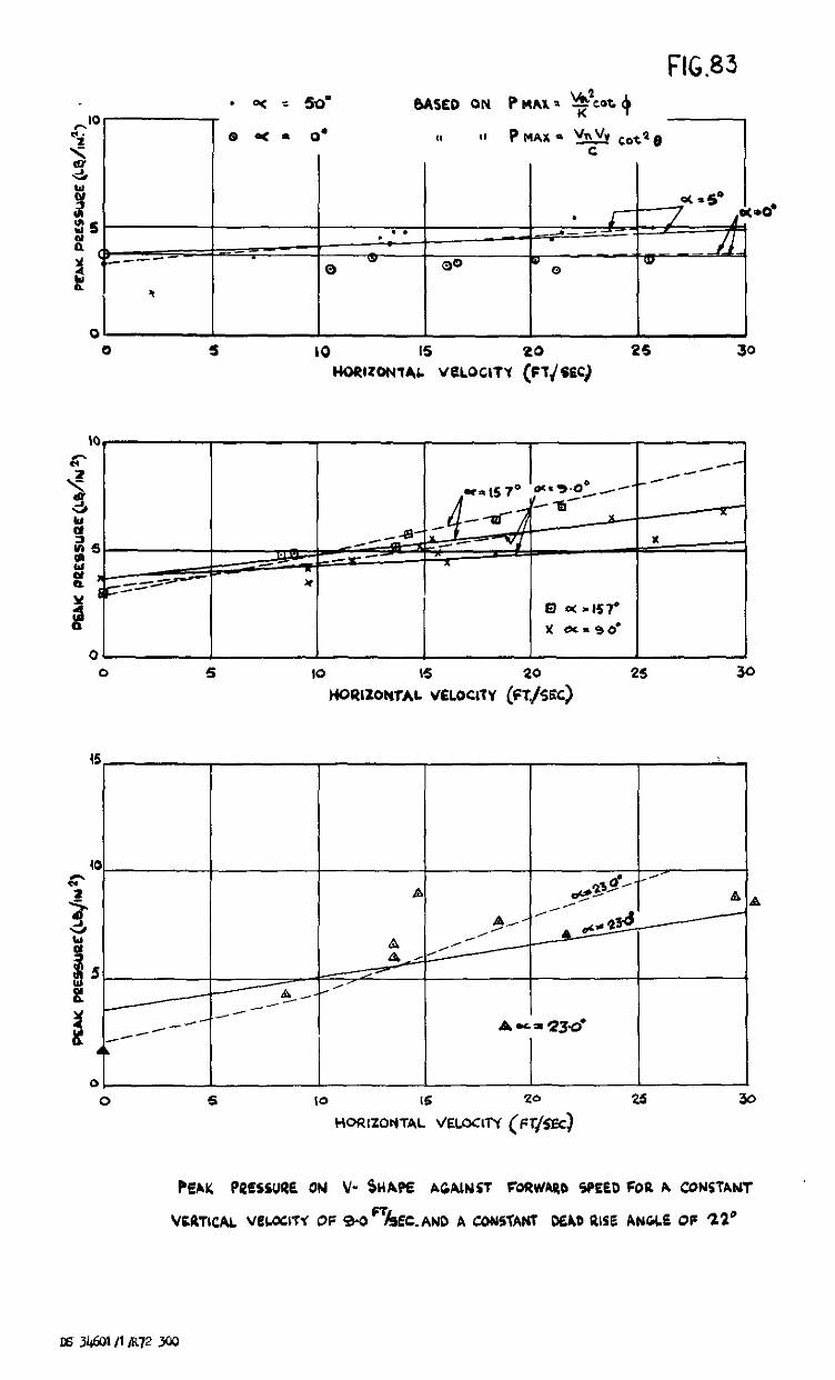
FIG.83
0 5 IO 25
I I I I I I 0 5 10 I5 20 2s 30
HoRl20N1AL VELOCITY (m/SEC)
PEAK PRESSURE ON V- 5HAF.E AGAIN51 FoUVVARD SPEED FOR A CONClAW
VCRTICAI. VCL0cl-W OF 3-D%EC.AND A CDNHAM DEAD PLEE ANGLE OF 22’

C.P. No. 4 (10057) A.R C. Techmcal Report
York House, Kmgswaay, LONWN, w c.2 429 oxford seer, Iommi, w I PO Box 569, LONDON, SE1
13a Castle street, iaxtawnOH, 2 I St .4lldmw’s crescent, C.4RDIFP 39 Kmg street, MANCHBgTBR, 2 1 Tower Lane, BRISIUL, 1
2 Edmund Street, BIRMINOWM, 3 80 ChIchester street, BELFAST or from any Bookseller
1950
Pace ,s 6d. net **l*ltLl IY O..AT .a,,*,*
S.O. Code No. 229064