Embed Size (px)
Citation preview

1
Flexural Behaviour of Textile Reinforced Concrete
Composites: Experimental and Numerical
Evaluation
Natalie Williams Portal1, Lars Nyholm Thrane
2, Karin Lundgren
3
1CBI Swedish Cement and Concrete Research Institute, Borås, Sweden and
Department of Civil and Environmental Engineering – Structural Engineering,
Chalmers University of Technology, Gothenburg, Sweden
[email protected], +46 10 516 68 87
2Department of Building Technology – Concrete, Danish Technological Institute
(DTI), Taastrup, Denmark
3Department of Civil and Environmental Engineering – Structural Engineering,
Chalmers University of Technology, Gothenburg, Sweden
Abstract
Textile reinforced concrete (TRC) is an innovative high performance composite material which
has revealed many promising attributes in various applications but test methods and reliable
numerical models need to be established to reduce uncertainty and the need for extensive
experimental studies. The aim of this paper was to evaluate the flexural behaviour of carbon textile
reinforced TRC slabs both experimentally and numerically along with the characterization of the
material and interaction level properties. The experimental results characterizing the bond
behaviour were linked to the experimental behaviour of a rectangular TRC slab in bending through
numerical analyses. A 2D macro-scale FE-model of the tested TRC slab was developed based on
the related experimental input. Comparison of the numerical results to the experiments revealed
that the flexural failure was governed by bond, and reasonable agreement was obtained in terms of
crack development, deflections, maximum load, and failure mode. Accordingly, the experiments
further indicated that the flexural behaviour of TRC slabs is greatly influenced by the bond quality.
Keywords
Textile reinforced concrete (TRC); Flexural behaviour; Bond behaviour; Finite
element; Textile materials
2
1. Introduction
Textile reinforced concrete (TRC) has been coined as a versatile high performance
composite material, yet it has not been sufficiently acknowledged due to a lack of
design specifications. Test methods and databases in combination with reliable
numerical models need to be established to reduce uncertainty. Furthermore,
design standards are not formalized for TRC such that extensive experimental
programs are still needed to acquire approval for each individual application
(Lorenz et al. 2013).
The non-linear behaviour of TRC is typically characterized by means of flexural
(Peled et al. 1999; Rempel et al. 2015; Schladitz et al. 2012; Yin et al. 2013),
tensile (Colombo et al. 2013; Jesse 2004) and pull-out tests (Lorenz et al. 2013;
Xu and Li 2007). Considering the case of a load bearing sandwich façade panel,
the structure can face load combinations which could involve, i.e. shear and
tensile forces, as well as bending moments (Shams et al. 2014). Accordingly,
numerous experiments need to be conducted to gain sufficient understanding of
the combined behaviours. In such design cases, it is most valuable to make use of
a simplified model taking into consideration homogenized special characteristics
of TRC, i.e. assuming bond-slip behaviour between textile and concrete (Hegger
et al. 2006). Other modelling levels could additionally be applied to investigate
more detailed aspects such as the behaviour of each filament (Banholzer et al.
2006) or crack bridging properties of yarns (Hegger et al. 2006) but these can
become computationally expensive and required input parameters are difficult to
quantify.
The one-way flexural behaviour of TRC in the form of thin slabs (Krüger 2004;
Peled et al. 1999) or as a beam strengthening solution (Schladitz et al. 2012) has
been typically studied by means of four-point bending tests. Early investigations
of the bearing behaviour of thin TRC specimens reinforced by AR-glass and
carbon textiles were presented in e.g. Hegger and Voss (2008) and the specimens
reinforced by a hybrid textile mesh of carbon and E-glass yarns was shown in Yin
et al. (2013). Despite the available research findings on this topic, a differing
combination of textile and cementitious matrix requires experimental
investigation, which is aimed for in this study on a particular carbon textile
reinforced concrete combination.

3
In this paper, it was of interest to observe the effect of high-performance carbon
textile fabric on the flexural behaviour of rectangular slabs with a thickness of 50
mm, which could be applied for façade panels. The thin thickness leads to a
lightweight structure, and is made possible by the use of non-corrosive nature of
textiles. Moreover, the complex interaction between the matrix and reinforcement
pertaining to the same carbon reinforced TRC used in the slabs was quantified by
means of pull-out tests. An approach linking the presented experimental methods
on various levels, i.e. material, interaction and component, to a simplified
numerical model is additionally addressed in this paper. The application of
simplified macroscale finite element (FE) modelling is proposed to gain a better
understanding of the failure mechanism and crack development of a rectangular
one-way TRC slab in bending which is typically challenging to capture
experimentally.
2. Materials
TRC specimens included in this work were composed of one layer of textile
reinforcement fabric embedded in a fine-grained concrete matrix.
A commercially available carbon textile fabric was applied throughout the
experimental study. The matrix consisted of a self-compacting concrete having an
aggregate size, dmax, of 4 mm. The material properties for the matrix and
reinforcement are described in the following sections.
2.1. Textile reinforcement fabric
TRC research efforts have primarily been focused on the development of AR-
glass, mostly due to their overall suitable mechanical properties, cost effectiveness
and availability. However, the application of carbon fibres in the form of fabrics
has become the subject of recent TRC research due to the fact that this material is
chemically inert (Micelli and Nanni 2004; Scheffler et al. 2009) and generally has
superior properties to AR-glass in terms of tensile strength and modulus of
elasticity. Carbon textile reinforcement typically consists of heavy-tow yarns,
which means that they have a larger cross-sectional area. This feature can lead to a
higher load-bearing capacity of a structure (Schladitz et al. 2012). General
material and mechanical properties made available by the producer for the carbon
textile reinforcement is given in Table 1 and an overview of the fabric is shown in

4
Fig. 1. These data were further applied as input on the material level in the FE
model (see Section 5). Experimental verification of these properties was not
conducted in this scope of work; yet, due to the variability in test methods
generally applied to characterize textile reinforcement properties, it could be
worthwhile to verify these in future work.
Table 1 Properties of the investigated carbon textile reinforcement fabric.
Fig. 1 Overview of the carbon textile reinforcement fabric.
2.2. Cementitious matrix
The cementitious matrix in TRC is generally composed of cement, fine-grained
particles, cement replacement materials (CRM) and a lower water-cement ratio
(w/c). When designing the mix composition, it was important to aim for a highly
flowable and self-compacting material which could adequately penetrate the
openings of the textile reinforcement fabric and to bear in mind the desired
thickness of the structure. In TRC, a fine-grained concrete having a maximum
aggregate size of less than 2 mm is commonly applied to achieve a superior bond

5
with the textile fabric, however this could in turn increase shrinkage of the matrix
and the need for larger quantities of cement paste. As such, the mix composition
applied in this experimental study, listed in Table 2, had a density, ρ, of 2240
kg/m3, w/c ratio of 0.4 and a maximum aggregate size, dmax, of 4 mm. The
chemical admixture applied, a polymer-based superplasticizer, helped reduce the
water-cement ratio which in turn allows for an increase in strength. Mineral
admixtures such as fly ash and microsilica were also included primarily to
improve the workability of the fresh concrete, reduce the cement quantity and
possibly increase the interfacial bond with the textile fabric.
Table 2 Mix composition of the fine-grained concrete matrix (w/c 0.40).
General material testing of the hardened concrete was included in the scope of this
experimental study, such that cylinders were cast and cured in water at 20°C until
testing. The mean compressive strength of hardened concrete, fc, was determined
experimentally on cylinders (Ø150/300 mm and Ø100/200 mm) according to EN
12390-3 (2009). Measurements were taken at 7, 14 and 99 days, which were
conducted in parallel with the flexural and pull-out test schedule. The mean
compressive strength of two Ø100/200 mm cylinders at 7 and 14 days was
measured as 36.1 MPa (std dev, σ=0.4) and 47.5 MPa (std dev, σ=1.1),
respectively. At 99 days, the mean compressive strength related to three Ø150/300
mm cylinders amounted to 84.7 MPa (std dev, σ=1.2). The tensile strength of the
hardened concrete was quantified on cylinders (Ø150/300 mm) using a tensile
splitting test based on EN 12390-6 (2009). This method consists of loading a
concrete cylinder placed on its side in a similar testing machine to that used for
compression testing. The tensile cylinder splitting strength, fct,sp , can be linearly
related to the axial tensile strength, fctm, using a correlation coefficient of 1.0
6
according to fib Model Code 2010 (2013). The mean tensile splitting strength,
fct,sp, was exclusively measured at 99 days for two specimens as 4.7 MPa (std dev,
σ=0.5). The four-point bending and pull-out tests were conducted at 99 days, such
that the resulting mean compressive strength of 84.7 MPa was applied throughout
the analyses enclosed in this study.
Due to the limited output of these applied experimental methods, other
mechanical properties required as input in the non-linear FE analysis (Section 5)
were estimated using available empirical expressions. The development of mean
compressive strength with time at 20°C, fcm(t), was calculated according to EN
1992-1-1 (2008) as a relation of the cement type and 28 day mean compressive
strength. Based on this expression, the cylinder compressive strength at 28 days
was back calculated to be 51.6 MPa using the measured data corresponding to 14
days. In addition, Young’s modulus and the fracture energy were computed using
fib Model Code 2010 to be 40 GPa based on the compressive strength at 28 days
and 99 N/m related to the tested tensile strength, respectively. Young’s modulus
and the fracture energy were calculated assuming a lightweight aggregate concrete
with normal weight sand. It should be noted that these applied empirical equations
are not necessarily tailored to fine-grained concrete or thin specimens, such that
they result in an estimation of the actual behaviour. A verification of these applied
equations by means of more comprehensive experimental tests should be verified
in future work.
3. Experimental Procedures
The scope of the experimental work encompassed the characterization of the one-
way flexural behaviour of rectangular TRC slabs and the pull-out behaviour of
thin TRC plates. Test specimens were cast and tested at the Danish Technological
Institute (DTI). It was of interest to investigate the use of a commercially
available carbon textile fabric in 50 mm thick slabs which could eventually be
applied for façade panels. Furthermore, pull-out tests were conducted on TRC
specimens composed of the same carbon textile fabric and concrete matrix
investigated in the flexural tests. It should be noted that the pull-out tests have
also been reported by the authors in Williams Portal et al. (2014), as such a
detailed analysis of these particular tests is not provided in this paper.

7
3.1. Four-point bending
The flexural behaviour of one-way TRC slabs was investigated by means of four-
point bending tests. This level of investigation is considered as the component
level in this study, which will be linked to the material and interaction levels via
FE-modelling in Section 5. The specimens had dimensions of 1000 x 200 x 50
mm with one layer of carbon textile fabric positioned at 7.5 mm from the bottom
edge of the slab (see Fig. 2). The warp yarns of the fabric were orientated
longitudinally such that they carried the tensile load resulting from the one-way
bending. One layer of carbon textile fabric corresponded to a longitudinal cross-
sectional area of 12.8 mm2 and a reinforcement ratio of 0.13%.
Fig. 2 Specimen geometry (a) and four-point bending test setup (b).
During casting, the edges of the fabric were fastened by the formwork such that
the fabric became slightly taut yet not pre-stressed which could potentially
slightly reduce the initial waviness of the fabric, increase peak load and decrease
slip. The specimens were removed from their formwork after 24 hours and stored
in a sealed and dry environment of 30°C until testing.
The four-point bending test setup, illustrated in Fig. 2 was configured in a way
that the slab was placed upside down compared to when it was cast and the load
was applied from beneath. The test specimen was placed on a loading beam with
two steel rods separating the applied load, P, by a distance of 400 mm into two
line loads, P/2. The support consisted of two aluminium profiles, of which one of
the steel rods and profiles could rotate at the bottom (not shown in Fig. 2) in order
to ensure that both line loads were uniformly distributed across the test specimen.
The load was applied by a hydraulic jack placed on a load cell. A displacement
transducer was mounted on an aluminium profile on top of the test specimen to
measure the midspan deflection relative to the supports. The deflection and
8
corresponding applied load were measured and stored every second using a data
logger.
3.2. Pull-out tests
A critical factor influencing the structural behaviour of TRC is in fact the complex
compatibility between the textile reinforcement yarn and the matrix (Zastrau et al.
2003), primarily due to the inherent heterogeneous structure of the yarn. This
interfacial behaviour, categorized as the interaction level in this study, becomes a
critical input parameter for numerical models developed to analyse the component
behaviour of TRC (see Section 5). Pull-out tests were applied to characterize the
bond behaviour of the particularly investigated carbon reinforced TRC
combination. The pull-out test setup and specimen configuration applied in this
study was designed based on the double-sided unsymmetrical test by (Krüger
2004) and Lorenz and Ortlepp (2012). The pull-out tests presented, as shown in
Fig. 3, were conducted on thin rectangular TRC specimens reinforced by a
centrally cast layer of carbon textile fabric with the dimensions of 400 x 100 x 15
mm. The thickness of the specimens was established to simulate the cover
thickness of 7.5 mm chosen for the rectangular TRC slabs tested in flexure.
Furthermore, the specimens were divided into a shorter embedment length zone
and longer anchorage length zone. The prescribed embedded length, denoted as B
in Fig. 3, was limited to the shorter end of the specimen by means of a single saw
cut crossing the yarn to be tested and a breaking point marked by two saw cuts
thus isolating an individual examined yarn. This configuration ensures that the
location of crack initiation takes place at the breaking point, as such the breaking
or rupture of the yarn does not necessarily take place at this location.

9
Fig. 3 Overview of the pull-out test setup (Williams Portal et al. 2014).
The embedment length was arbitrarily defined as Short (25 mm), Medium (50
mm) and Long (75 mm). These embedment lengths were selected to be able to
quantify the bond capacity and associated failure modes, e.g. pull-out and rupture.
Three specimens were produced for each selected embedment length in order to
obtain representative average pull-out behaviour; however, at least two specimens
per embedment length group were successfully tested. Additional information
regarding the experimental campaign related to the pull-out tests is reported in
Williams Portal et al. (2014).
4. Experimental Results
The experimental results related to the one-way flexural behaviour of rectangular
TRC slabs and the pull-out tests of thin TRC plates are presented in the following
sections. Firstly, the flexural results pertaining to the component level are
discussed in Section 4.1 according to the load versus midspan displacement
relationship, crack pattern and estimated failure mode. As for the output on the
interaction level, the pull-out test results and corresponding local bond-stress
behaviour are presented in Section 4.2. To be able to further describe and

10
understand the complex heterogeneous behaviour of TRC in bending, the
observed behaviours on the interaction and component levels were further coupled
in a numerical model simulating the four-point bending of the TRC slabs (see
Section 5).
4.1. Four-point bending tests
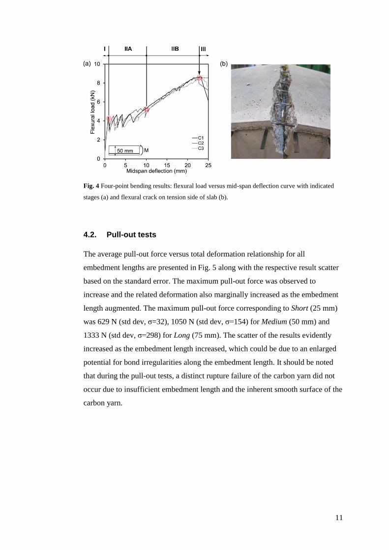
The flexural behaviour investigated for 50 mm TRC rectangular one-way slabs
reinforced by carbon fabric, denoted as C1-C3, was found to reasonably correlate
within the sample set as depicted in Fig. 4. To describe the flexural behaviour of
TRC, four states are typically defined to draw a parallel between conventionally
reinforced concrete and TRC (Brameshuber 2006): State I (uncracked concrete),
State IIA (crack formation), State IIB (crack stabilization), and State III (failure).
The elastic pre-cracking state is defined as State I whereby the behaviour was
primarily governed by the stiffness of the cementitious matrix. For C1-C3, first
cracking took place at an average load of 4.3 kN (std dev, σ=0.1) which was
followed by an abrupt unloading due to the brittle nature of the load redistribution
to the textile reinforcement. The extent of load drop or so-called delayed load
distribution is thought to be a function of the initial geometric waviness of the
fabric (Hartig et al. 2009), reinforcement area and the quality of the bond between
the reinforcement and matrix. In the case of a poor bond, low filament stiffness
and strength and/or minimal reinforcement amount, a greater deformation is
required to activate load transfer from the matrix to the reinforcement. Moreover,
State IIa was marked by the formation of multiple cracking (4-6 cracks) indicated
by the apparent load jumps with minimal load increase. The crack formation
eventually stabilized in State IIb, which was noted by a gain of stiffness said to be
governed by the properties of the textile reinforcement (Orosz et al. 2010). This
gain in stiffness is often denoted as strain hardening in the case of uniaxial tension
(Brameshuber 2006) but can be seen as a form of deformation hardening in
flexure. When failure was reached in State III at an average load of 8.5 kN (std
dev, σ=0.1) and midspan deflection of 22.6 mm (std dev, σ=0.7), it is thought that
a combination of pull-out and rupture occurred as can be observed in Fig. 4 where
the tension side of the specimen is shown. Nevertheless, the exact mode of failure
was unclear during testing, which is why this aspect was further evaluated using
FE-analysis in this paper (Section 5).
11
Fig. 4 Four-point bending results: flexural load versus mid-span deflection curve with indicated
stages (a) and flexural crack on tension side of slab (b).
4.2. Pull-out tests
The average pull-out force versus total deformation relationship for all
embedment lengths are presented in Fig. 5 along with the respective result scatter
based on the standard error. The maximum pull-out force was observed to
increase and the related deformation also marginally increased as the embedment
length augmented. The maximum pull-out force corresponding to Short (25 mm)
was 629 N (std dev, σ=32), 1050 N (std dev, σ=154) for Medium (50 mm) and
1333 N (std dev, σ=298) for Long (75 mm). The scatter of the results evidently
increased as the embedment length increased, which could be due to an enlarged
potential for bond irregularities along the embedment length. It should be noted
that during the pull-out tests, a distinct rupture failure of the carbon yarn did not
occur due to insufficient embedment length and the inherent smooth surface of the
carbon yarn.

12
Fig. 5 Pull-out test results for specimens with varying embedment lengths: pull-out force versus
deformation with scatter based on standard error.
A suitable local bond stress-slip relationship, when applied in a component level
model, should generate results that correlate with the measured bond behaviour of
the TRC plate specimen, i.e. global level. The shape of the local bond stress-slip
function is dependent on numerous parameters, e.g. material properties of the
concrete matrix, reinforcement geometry and surface, as well as the configuration
and stiffness of the mesh cross-threads. Numerical or analytical methods are
commonly applied to estimate a local bond-slip function. The local bond stress-
slip functions for carbon reinforced TRC were initially calibrated to match the
experimental results in Williams Portal et al. (2014). A first estimate of a local
bond-slip function was made according to the experimental results related to the
test specimens constituting a short embedment length. This first estimate was then
used as input in a global analysis resulting in a force versus crack opening
relation. From comparisons with the measured results, the local bond versus slip
was corrected in several steps until reasonable agreement was found on the global
level in relation to the TRC component behaviour. This calibrated local behaviour
provided in Fig. 6 underwent further adaption in terms of the estimated contact
perimeter which is why this curve slightly differs from that presented in Williams

13
Portal et al. (2014). Moreover, this local bond behaviour was subsequently applied
in the developed numerical model simulating the four-point bending of the TRC
slabs (see Section 5).
Fig. 6 Calibrated local bond-slip relationship.
5. Investigation using FE-modelling
A non-linear macroscale 2D finite element (FE) model was developed based on
the component level four-point bending tests related to the 50 mm thick TRC
slabs reinforced by carbon textile fabric. The commercial software DIANA
(DIsplacement ANAlyser) with pre- and post-processor Midas FX+ was used to
perform the analyses. The ability to interconnect the experimental findings from
the various investigated levels, i.e. material and interaction, to the TRC
component level was studied by means of the developed model. The experimental
results related to the TRC component level from the four-point bending tests were
used to validate the outcome of the FE model. Moreover, through these numerical
analyses it was important to gain further insight in the failure mode, as well as to
identify difficulties and uncertainties in the modelling of TRC. Preliminary
modelling work was also carried out in related work by Pettersson and Thorsson
(2014).

14
5.1. Model
The entire geometry of the specimen and experimental setup were modelled in
order to be able to yield a crack development pattern comparable to the
experimental results of the four-point bending (see Fig. 7). The aforementioned
geometry, material properties (material level, Section 2) and bond-slip
relationship (interaction level, Section 4.2) were used as input data in the model.
Details pertaining to the applied material models are described in the following
section. An element size of 2.5 x 2.5 mm was selected for the entire geometry.
The point load was applied as a fixed deformation and equilibrium was solved
using secant tangent iterations which yielded the most stable solution. The self-
weight was assumed to be negligible in the analysis as it was found to have a
minor influence on the overall results such that it’s bending moment corresponded
to 2% of the total bending moment of the applied load. Deformation controlled
loading means that the behaviour, especially during the cracking state, can be
followed more accurately and that the results can be more easily compared to the
test results. A rigid beam connection as a statically determinate system was
included in the model to enable the deformation-controlled loading for more than
one point load as recommended in Broo et al. (2008) (see Fig. 7). The nodes
corresponding to the location of the point loads (P/2) on the specimen had the
same displacement in the y-direction as the end nodes of the rigid links connected
to the rigid beam; displacements in the x-direction were not tied between these
nodes. The rigid beam was restrained at one end along the x-axis and rotation
about the z-axis. To avoid stress concentrations or singularities at the locations of
reaction forces and applied loads (i.e. singular nodes), dummy beams (L6BEN, 2
nodes), with low stiffness and density, were introduced at these points, to allow
for the interaction of the surrounding nodes. This interaction can be further
distinguished as eccentricity tying, wherein surrounding slave nodes were
eccentrically connected to a master node (see Fig. 7). In this case, the translation
along the y-axis and rotation about the z-axis corresponding to the slave nodes
were eccentrically connected to the centre master node.

15
Fig. 7 Idealized FE-model and special features.
The concrete matrix and textile reinforcement were modelled using 2D
quadrilateral plane stress elements (Q8MEM, 4 nodes) and 1D truss-bar elements
(L2TRU, 2 nodes), respectively. The Q8MEM elements are based on linear
interpolation and default Gauss integration (2 x 2), while the L2TRU elements are
directly integrated (1-point). The interface of the matrix and reinforcement was
defined by 2D line-interface elements with bond-slip relationship (L8IF, 4 nodes)
which has nodes at the same coordinates as the connecting concrete elements. The
purpose of the interface elements is to allow slip while still transferring stress
between the concrete and the textile reinforcement. The connectivity between the
element types is further described in Pettersson and Thorsson (2014) and
Williams Portal et al. (2013).
5.2. Material models
5.2.1. Textile reinforcement
The textile reinforcement in the longitudinal direction of the rectangular TRC slab
was bundled in a monolithic bar (see Fig. 8) similar to what has been applied in
other modelling approaches (Azzam and Richter 2011; Holler et al. 2004;
Williams Portal et al. 2013; Williams Portal et al. 2014). The monolithic bar is
assumed to have one bond interface with the concrete matrix which therefore
neglects the actual uneven bond distribution across the yarn structure. Considering

16
a cross-sectional width of dx, a number of longitudinal yarns are positioned
according to a given centre to centre yarn spacing, s, within dx. Each individual
longitudinal yarn has a contact perimeter assumed to be circular, Cf, and a circular
area, Af. An equivalent contact perimeter, Ct,l, and area, At,l, of the monolithic bar
are computed by multiplying Cf and Af respectively by the number of individual
longitudinal yarns found within dx.
Fig. 8 Depiction of the monolithic bar assumption (t is the thickness of the cross-section and s is
the centre-centre yarn spacing).
The tensile properties of the carbon textile reinforcement were not explicitly
quantified in this work, such that the properties made available by the producer
were applied in the FE-model (see Table 1). The monolithic bar was assigned a
linear-elastic stress-strain law with no limiting tensile strength. To describe the
interaction between the textile reinforcement and the concrete matrix, so-called
bond behaviour, the local bond stress-slip relationship previously presented in Fig.
6 was assigned to the 2D line interface elements.
Modelling with two interfaces between the external and internal filaments have
indicated insignificant differences when compared to modelling with one bond
interface (Holler et al. 2004). The quantification of the relative displacement
between the external and internal filaments would require an iterative and time
consuming process which is thought to be more relevant for more detailed
modelling scales, i.e. meso- and microscales. Nevertheless, it should be
mentioned that the bond behaviour included in this model takes into consideration
the effect of the lateral yarns of the fabric on the pull-out of one yarn as a result of
the test specimen configuration.

17
5.2.2. Concrete matrix
The fine-grained concrete matrix was modelled as a homogeneous material using
the properties presented in Section 2.2. The compressive strength and tensile
splitting strength of the concrete were experimentally quantified and the fracture
energy and modulus of elasticity were estimated using fib Model Code 2010
(2013). The mechanical behaviour of the concrete material was assumed to follow
typical curves for compressive and tensile behaviours provided by TNO DIANA
(2014). Furthermore, a total strain based crack model with rotating crack was
defined for the fine-grained concrete, wherein the crack direction continuously
rotates according to the principal directions of the strain vector. This model
includes both the tension softening and compressive behaviours, which were
modelled by non-linear Hordijk tension softening and Thorenfeldt compression
curves available in TNO DIANA (2014). Since the Thorenfeldt curve is based on
the compressive strength of cylinders with a length of 300 mm, it was found
necessary to correct the post-peak part of the curve. In this case, the correction
was effectuated according to a scaling factor (LTHORE) implemented in TNO
DIANA (2014). The modification of the curve, depicted in Fig. 9 allowed for the
localization of strains in single element rows. Also, a crack band width equal to
the element size (2.5 mm) was chosen as the cracks generally localized in single
element rows.
Fig. 9 Modified versus unmodified Thorenfeldt compression behaviours (a) and emphasis on the
shift of strain starting at the peak compressive strength (b). Modification based on scaling factor
LTHORE in TNO DIANA (2014).
Another feature which was incorporated in the model was the inclusion of so-
called voids created by the assumed exclusion of the lateral yarns of the fabric as

18
illustrated in Fig. 7. As well, it is a known fact that stress concentrations and crack
formation typically occur at the lateral yarn locations (Azzam and Richter 2011;
Krüger 2004), thus justifying the need for the localized adjustment of the tensile
properties of the concrete. To take this feature into account, the tensile strength
and fracture energy of localized concrete elements situated at the reinforcement-
matrix interface were decreased in relation to the ‘loss of concrete area’. It is to
say that the approximate cross-sectional area of the lateral yarn (1.83 mm2) was
subtracted from the concrete element area (6.25 mm2). The ratio between the
reduced area and the total area of the concrete element resulted in the estimated
remaining capacity of the concrete element in the location of a lateral yarn (71%).
As an initial estimation, the tensile strength and fracture energy previously
mentioned in Section 2.2 were reduced by the same factor (29%) leading to 3.3
MPa and 70 N/m, respectively.
5.3. FE results
5.3.1. General flexural behaviour
The flexural behaviour along with the failure mode could be simulated within a
reasonable level of accuracy using the developed 2D macroscale model of the
presented four-point bending test. To observe the correlation between the
numerical and experimental results (see Fig. 4), the respective flexural load versus
midspan deflection relationships were plotted against each other. Based on the
numerical results in Fig. 10, first cracking (A) occurred at a load level of 4.42 kN
and a deflection of 0.75 mm. Multiple cracking took place thereafter which was
followed by a deformation hardening behaviour with a comparable stiffness to
that of the experimental curves. The TRC specimen eventually underwent a bond
failure in the analysis at an ultimate load of 9.58 kN and deflection of 25.30 mm,
which is marked by the growth of the end slip at the outer edges of the specimen
as further described in Section 5.3.2. Moreover, a slight overestimation of the load
at first cracking was obtained which occurred at a lower deflection value as
presented in Table 3. As for the load and midspan deflection at failure, these
values were marginally higher than the experimental results which could be due to
the following factors: scatter in pull-out test results leading to uncertainty in local
bond stress-slip curve, overestimation of the deformation, i.e. total slip, due to the
exclusion of internal filament slip, as well as the exclusion of the reduction of the

19
cross-sectional area of yarns caused by successive failure of filament rupture
(Lepenies 2007). Furthermore, the frictional zone of the local bond stress-slip
curve, i.e. bond stress decline after peak, was not adequately captured. The
configuration of the pull-out test setup and choice and placement of measurement
devices, i.e. LVDT, did not allow for the precise measurement of the pull-out
failure due to a sudden release of the LVDT upon failure. Other modifications to
the model could include the effect of the end support pressure and/or the impact of
the curvature (Hegger et al. 2008; Voss et al. 2006) on the bond; these effects
would however cause an increased capacity. Lastly, it is thought that the inclusion
of experimental compressive and tensile behaviours pertaining to the given fine-
grained concrete could also help improve the correlation between the numerical
and experimental results.
Fig. 10 Comparison of experimental and FE-results.
Table 3 Comparison between average experimental flexural results and FE-analysis.
20
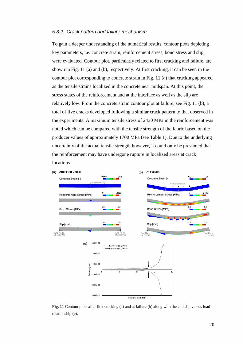
5.3.2. Crack pattern and failure mechanism
To gain a deeper understanding of the numerical results, contour plots depicting
key parameters, i.e. concrete strain, reinforcement stress, bond stress and slip,
were evaluated. Contour plot, particularly related to first cracking and failure, are
shown in Fig. 11 (a) and (b), respectively. At first cracking, it can be seen in the
contour plot corresponding to concrete strain in Fig. 11 (a) that cracking appeared
as the tensile strains localized in the concrete near midspan. At this point, the
stress states of the reinforcement and at the interface as well as the slip are
relatively low. From the concrete strain contour plot at failure, see Fig. 11 (b), a
total of five cracks developed following a similar crack pattern to that observed in
the experiments. A maximum tensile stress of 2430 MPa in the reinforcement was
noted which can be compared with the tensile strength of the fabric based on the
producer values of approximately 1700 MPa (see Table 1). Due to the underlying
uncertainty of the actual tensile strength however, it could only be presumed that
the reinforcement may have undergone rupture in localized areas at crack
locations.
Fig. 11 Contour plots after first cracking (a) and at failure (b) along with the end slip versus load
relationship (c).

21
Additionally, to further verify the failure mode in the analysis as an anchorage
failure, the growth of the end slip at both ends of the interface was plotted against
the flexural load, see Fig. 11 (c). The scale was adjusted to show the growth
before failure occurs. From these results, it can be observed that the end slip
started to grow at a load of approximately 8.8 kN which led to an eventual
anchorage failure in the analysis as the end slip significantly increased. Based on
this numerical analysis, it can be supposed that the failure mechanism which took
place in the four-point bending experiments was indeed an anchorage failure. The
partial rupture of the textile fabric could however not be captured in this particular
model, but certainly this partial rupture contributed to the ultimate failure in the
experiments.
6. Conclusions
This paper focused on presenting an approach linking experimental methods from
material, interaction and component levels to numerical investigations for thin
rectangular TRC slabs reinforced by carbon textile fabric. The material level
properties were experimentally and analytically quantified for the cementitious
matrix, while the textile properties were values from the producer. The interaction
level was represented by a calibrated local bond-slip curve obtained from pull-out
tests. The component level was characterized by the one-way flexural behaviour
of these slabs which resulted in multiple cracking and deformation hardening. The
failure mechanism was however difficult to characterize during testing yet it was
observed to be a combination failure of pull-out and partial filament rupture.
The 2D macroscale model developed for the four-point bending test of the carbon
reinforced TRC slabs generated comparable results to the experimental ones with
an adequate level of accuracy. The analyses resulted in a slight over prediction of
the ultimate capacity and revealed that failure was governed by bond; this failure
mode was difficult to determine in the four-point bending tests alone but seem
trustworthy when looking at the results together. The underlying accuracy of the
modelling output of the flexural behaviour of the TRC slab can be further
improved by refining the experimental methods applied on the various levels of
investigation and by increasing the number of experimental samples.

22
Acknowledgments
The presented research was funded by the European Community’s Seventh Framework
Programme under grant agreement NMP2-LA-2009-228663 (TailorCrete) and FORMAS (Homes
for Tomorrow). More information about the research projects, TailorCrete and Homes for
Tomorrow, can be found at www.tailorcrete.com and www.homesfortomorrow.se, respectively.
References
Azzam A, Richter M (2011) Investigation of Stress Transfer Behavior in Textile
Reinforced Concrete with Application to Reinforcement Overlapping and
Development Lengths. Paper presented at the 6th Colloquium on Textile
Reinforced Structures (CTRS6), Dresden, Germany,
Banholzer B, Brockmann T, Brameshuber W (2006) Material and bonding
characteristics for dimensioning and modelling of textile reinforced
concrete (TRC) elements Mater Struct 39:749-763 doi:10.1617/s11527-
006-9140-x
Brameshuber W (ed) (2006) Report 36: Textile Reinforced Concrete-State-of-the-
Art Report of RILEM TC 201-TRC vol 36. RILEM publications,
Broo H, Lundgren K, Plos M (2008) A guide to non-linear finite element
modelling of shear and torsion in concrete bridges. Report 2008:18,
Chalmers University of Technology
Colombo I, Magri A, Zani G, Colombo M, di Prisco M (2013) Erratum to: Textile
Reinforced Concrete: experimental investigation on design parameters
Mater Struct 46:1953-1971 doi:10.1617/s11527-013-0023-7
EN 1992-1-1 (2008) EN 1992-1-1:2005 Eurocode 2: Design of concrete
structures. Comité Européen de Normalisation (CEN),
EN 12390-3 (2009) Testing hardened concrete - Part 3: Compressive strength of
test specimens. Comité Européen de Normalisation (CEN),
EN 12390-6 (2009) Testing hardened concrete - Part 6: Tensile splitting strength
of test specimens. Comité Européen de Normalisation (CEN),
fib Model Code 2010 (2013). Fédération Internationale du béton, Lausanne
Hartig J, Jesse F, Häußler-Combe U Influence of different mechanisms on the
constitutive behaviour of textile reinforced concrete. In: 4th Colloquium
on Textile Reinforced Structures (CTRS4), Dresden, Germany, 2009.
Hegger J, Schneider H, Voss S, Bergmann I (2008) Dimensioning and application
of textile-reinforced concrete ACI Special Publication 250
Hegger J, Will N, Bruckermann O, Voss S (2006) Load–bearing behaviour and
simulation of textile reinforced concrete Mater Struct 39:765-776
doi:10.1617/s11527-005-9039-y
Hegger J, Voss S (2008) Investigations on the bearing behaviour and application
potential of textile reinforced concrete Engineering structures 30:2050-
2056
Holler S, Butenweg C, Noh SY, Meskouris K (2004) Computational model of
textile-reinforced concrete structures Computers & Structures 82:1971-
1979 doi:10.1016/j.compstruc.2004.03.076
Jesse F (2004) Tragverhalten von Filamentgarnen in zementgebundener Matrix
(Load bearing behaviour of filament yarns in a cementitious matrix).
Technische Universität Dresden

23
Krüger M (2004) Vorgespannter textilbewehrter Beton (Prestressed textile
reinforced concrete). Dissertation, University of Stuttgart
Lepenies IG (2007) Zur hierarchischen und simultanen multi-skalen-analyse von
textilbeton (On the Hierarchical and Integrated Multi Scale Analysis of
Textile Reinforced Concrete). Dissertation, Technische Universität
Dresden
Lorenz E, Ortlepp R (2012) Bond behavior of textile reinforcements-development
of a pull-out test and modeling of the respective bond versus slip relation.
In: High Performance Fiber Reinforced Cement Composites 6. Springer,
pp 479-486
Lorenz E, Schütze E, Schladitz F, Curbach M (2013) Textilbeton–Grundlegende
Untersuchungen im Überblick Beton und Stahlbetonbau 108:711-722
Micelli F, Nanni A (2004) Durability of FRP rods for concrete structures
Construction and Building Materials 18:491-503
Orosz K, Blanksvärd T, Täljsten B, Fischer G (2010) From material level to
structural use of mineral-based composites—an overview Advances in
Civil Engineering
Peled A, Bentur A, Yankelevsky D (1999) Flexural performance of cementitious
composites reinforced with woven fabrics Journal of materials in civil
engineering 11:325-330
Pettersson M, Thorsson P (2014) FE-modelling of Textile Reinforced Concrete
Facade Elements. Master's Thesis, Chalmers University of Technology
Rempel S, Kulas C, Hegger J (2015) Bearing Behavior of Impregnated Textile
Reinforcement. Paper presented at the 3rd ICTR International Conference
on Textile Reinforced Concrete Aachen, Germany,
Scheffler C, Gao S, Plonka R, Mäder E, Hempel S, Butler M, Mechtcherine V
(2009) Interphase modification of alkali-resistant glass fibres and carbon
fibres for textile reinforced concrete I: Fibre properties and durability
Composites Science and Technology 69:531-538
Schladitz F, Frenzel M, Ehlig D, Curbach M (2012) Bending load capacity of
reinforced concrete slabs strengthened with textile reinforced concrete
Engineering structures 40:317-326
Shams A, Horstmann M, Hegger J (2014) Experimental investigations on Textile-
Reinforced Concrete (TRC) sandwich sections Composite Structures
118:643-653
TNO DIANA (2014) Finite Element Analysis User's Manual - Release 9.5.
Williams Portal N, Lundgren K, Walter AM, Frederiksen JO, Thrane LN (2013)
Numerical Modelling of Textile Reinforced Concrete. Paper presented at
the VIII International Conference on Fracture Mechanics of Concrete and
Concrete Structures, Toledo, Spain, 10-14 March,
Williams Portal N, Perez Fernandez I, Thrane Nyholm L, Lundgren K (2014)
Pull-out of textile reinforcement in concrete Construction and Building
Materials 71:63-71
Voss S, Hegger J, Hegger J, Brameshuber W, Will N Dimensioning of textile
reinforced concrete structures. In: Proceedings of the 1st International
RILEM Symposium on textile reinforced concrete, RILEM Publication
SARL, France, 2006. pp 151-160
Xu S, Li H (2007) Bond properties and experimental methods of textile reinforced
concrete Journal of Wuhan University of Technology--Materials Science
Edition 22:529-532 doi:10.1007/s11595-006-3529-9

24
Yin S, Xu S, Li H (2013) Improved mechanical properties of textile reinforced
concrete thin plate Journal of Wuhan University of Technology-Mater Sci
Ed 28:92-98 doi:10.1007/s11595-013-0647-z
Zastrau B, Richter M, Lepenies I (2003) On the Analytical Solution of Pullout
Phenomena in Textile Reinforced Concrete Journal of Engineering
Materials and Technology 125:38-43