Embed Size (px)
Citation preview

Flexible Plug and Play Communication Trial Report

Flexible Plug and Play FPP Communications Trial Report
UK Power Networks (Operations) Limited. Registered in England and Wales. Registered No. 3870728. Registered Office: Newington House, 237 Southwark Bridge Road, London, SE1 6NP Page2 of 38
Table of Contents
1.0 Document Control ........................................................................................................................................................ 3
1.1 Version History ........................................................................................................ Error! Bookmark not defined.
1.2 Associated Documents ............................................................................................................................................. 3
2.0 Introduction .................................................................................................................................................................. 4
2.1 Purpose .................................................................................................................................................................... 4
2.2 Scope ....................................................................................................................................................................... 4
3.0 Communications Trial overview ................................................................................................................................... 4
4.0 COM01 Trial - Communications network reliably and performance ............................................................................ 6
4.1 Trial requirements .................................................................................................................................................... 6
4.2 Trial activities ............................................................................................................................................................ 6
4.3 Analysing Communication Performance .................................................................................................................. 7
4.4 Schedule of the test ................................................................................................................................................ 12
4.5 Periods of no IEC 61850 traffic .............................................................................................................................. 13
4.6 ICMP latency ......................................................................................................................................................... 15
4.7 MMS latency ........................................................................................................................................................... 17
4.8 TCP Keep-Alive ...................................................................................................................................................... 19
4.9 Data Profile ............................................................................................................................................................. 20
5.0 COM02 Trial - Communications network supports Plug and Play features .............................................................. 24
5.1 Trial requirements .................................................................................................................................................. 24
5.2 Trial activities .......................................................................................................................................................... 24
5.3 Integrate a new RF mesh communications device to the FPP network ................................................................ 24
5.4 Update communications hardware in a seamless and quick method .................................................................... 26
6.0 COM03 Trial - Interoperability .................................................................................................................................... 27
6.1 Trial requirements .................................................................................................................................................. 27
6.2 Trial activities .......................................................................................................................................................... 27
7.0 COM04 Trial - Communications network offers high level of security ....................................................................... 29
7.1 Trial requirements .................................................................................................................................................. 29
7.2 Trial activities .......................................................................................................................................................... 29
7.3 Deploying and validating security in Communications platform ............................................................................. 29
8.0 Communication Trial Outcomes ................................................................................................................................ 38

Flexible Plug and Play FPP Communications Trial Report
UK Power Networks (Operations) Limited. Registered in England and Wales. Registered No. 3870728. Registered Office: Newington House, 237 Southwark Bridge Road, London, SE1 6NP Page3 of 38
1.0 Document Control
1.1 Associated Documents
Reference Document Source
1 DA.P0154.FPP Functional and Non-Functional Requirements Specification V1.0
2 PP P0168 FPP_Use Cases V1 1
3 P0157.FPP.High Level Design_v1.9
4 WS01.P0190.FPP.End to End Acceptance Test Report v4.0
5 Security deployment: Security implementation details, Q&A and planning
Flexible Plug and Play FPP Communications Trial Report
UK Power Networks (Operations) Limited. Registered in England and Wales. Registered No. 3870728. Registered Office: Newington House, 237 Southwark Bridge Road, London, SE1 6NP Page4 of 38
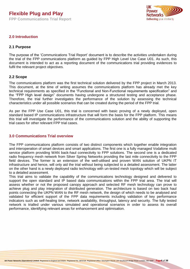
2.0 Introduction
2.1 Purpose
The purpose of the ‘Communications Trial Report’ document is to describe the activities undertaken during the trial of the FPP communications platform as guided by FPP High Level Use Case U01. As such, this document is intended to act as a reporting document of the communications trial providing evidences to fulfil the relevant project objectives.
2.2 Scope
The communications platform was the first technical solution delivered by the FPP project in March 2013. This document, at the time of writing assumes the communications platform has already met the key technical requirements as specified in the “Functional and Non-Functional requirements specification” and the “FPP High level design” documents having undergone a structured testing and acceptance phase. Therefore, the trial further investigates the performance of the solution by assessing the technical characteristics under all possible scenarios that can be created during the period of the FPP trial. As per the FPP Use Case U01, this trial is concerned with basic proving of a newly deployed, open standard based IP communications infrastructure that will form the basis for the FPP platform. This means this trial will investigate the performance of the communications solution and the ability of supporting the trial cases for other relevant FPP trial cases.
3.0 Communications Trial overview
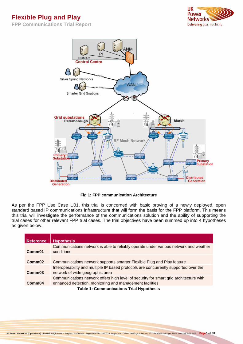
The FPP communications platform consists of two distinct components which together enable integration and interoperation of smart devices and smart applications. The first one is a fully managed Vodafone multi service platform providing WAN back-haul connectivity to FPP solutions. The second one is a dedicated radio frequency mesh network from Silver Spring Networks providing the last mile connectivity to the FPP field devices. The former is an extension of the well-utilised and proven WAN solution of UKPN IT infrastructure and hence, will only aid the trial without being subjected to a detailed assessment. The latter on the other hand is a newly deployed radio technology with un-tested mesh topology which will be subject to a detailed assessment. This trial aims to validate the capability of the communications technology designed and delivered to support the open standard and IP based data communications within the FPP trial area. The trial will assess whether or not the proposed canopy approach and selected RF mesh technology can prove to achieve plug and play integration of distributed generation. The architecture is based on two back haul points connecting the UKPN WAN to the RF mesh network, the design of which needs to be analysed and validated for efficient support of the FPP data requirements including validation of key performance indicators such as self-healing time, network availability, throughput, latency and security. The fully tested network is trialled under various simulated and operational scenarios in order to assess its overall performance, identifying relevant areas for enhancement and optimisation.
Flexible Plug and Play FPP Communications Trial Report
UK Power Networks (Operations) Limited. Registered in England and Wales. Registered No. 3870728. Registered Office: Newington House, 237 Southwark Bridge Road, London, SE1 6NP Page5 of 38
Fig 1: FPP communication Architecture
As per the FPP Use Case U01, this trial is concerned with basic proving of a newly deployed, open standard based IP communications infrastructure that will form the basis for the FPP platform. This means this trial will investigate the performance of the communications solution and the ability of supporting the trial cases for other relevant FPP trial cases. The trial objectives have been summed up into 4 hypotheses as given below.
Reference Hypothesis
Comm01
Communications network is able to reliably operate under various network and weather
conditions
Comm02 Communications network supports smarter Flexible Plug and Play feature
Comm03
Interoperability and multiple IP based protocols are concurrently supported over the
network of wide geographic area
Comm04
Communications network offers high level of security for smart grid architecture with
enhanced detection, monitoring and management facilities
Table 1: Communications Trial Hypothesis

Flexible Plug and Play FPP Communications Trial Report
UK Power Networks (Operations) Limited. Registered in England and Wales. Registered No. 3870728. Registered Office: Newington House, 237 Southwark Bridge Road, London, SE1 6NP Page6 of 38
4.0 COM01 Trial - Communications network reliably and performance
4.1 Trial requirements
The Flexible Plug and Play project aims to investigate the performance of the communications solution based the RF mesh infrastructure and its ability of supporting the communications required by the FPP technical solution during various seasonal changes and network loading conditions.
4.2 Trial activities
Improving Communication Performance
The performance monitoring of the first connected DG customer highlighted one of the hidden issues with the communications platform related to intermittent failures. This led to a series of investigation and testing on both WAN and RF mesh solutions to find the root cause of the issue generating huge learning from the project. The basic topology of the RF mesh network was based on multiple remote nodes communicating back to a central system via any one of four Master nodes. The FPP communications network was designed with fully dynamic RF mesh architecture, as such any RF mesh remote node at any part of the 700 square Km trial area would be capable of routing via any of the 4 RF mesh master nodes installed at the two back-haul sites. This was quite an innovative design which required synchronisation between the four master nodes using Master Failover Protocol (MFP) to achieve guaranteed failover functionality. This synchronisation mechanism determined which of the four master nodes has the best available route for each remote node and as such should be the single master to announce that route to the upstream WAN’s routing domain, disregarding the routes from the three remaining master nodes. The investigation identified a number of factors contributing to the suboptimal performance. The main cause of the issue was related to implementation issues on the WAN infrastructure devices which hindered the ability of the master nodes to fully synchronise with each other over the Wide Area Network (WAN). This resulted in intermittent failures of remote nodes and higher latencies due to sub-optimal or conflicting routings. A number of corrective actions were taken to resolve this issue as follows.
Removal of route summarization in the WAN in order to prevent the loss of cost metrics in the routes announced by the Master nodes. Loss of cost has led asymmetric routing of communications through the WAN
Addition of specific filter rules in the WAN routers at each backhaul sites to prevent a condition where the remote node routes learned by BGP were then re-distributed back to the substation routers, causing a conflict with RIP that led to the loss of routes and therefore loss of end-to-end communication capability
Re-location at each substation router of the Master Bridges’ Ethernet connection, as the HWIC module on the routers was found to be unable to reliably support multicast communications required by the Master Failover Protocol
The corrective actions led to a stable performance with high availability of remote nodes and lower latencies. The performance of the RF mesh network was further improved by network optimisation exercise which involved replacement and re-location of under-performing relays and reinforcement of additional relays in parts of the network with lower signal quality. The figure below shows the improvement in the latency for some devices communicating to the ANM after a number of corrective actions were taken as part of the fault resolution process.

Flexible Plug and Play FPP Communications Trial Report
UK Power Networks (Operations) Limited. Registered in England and Wales. Registered No. 3870728. Registered Office: Newington House, 237 Southwark Bridge Road, London, SE1 6NP Page7 of 38
. Latency comparison before and after resolution of issues
4.3 Analysing Communication Performance
Master Ebridge Utilisation
The RF Mesh is configured with Four Master Ebridges acting as the focal points for the mesh network. These are split with two devices located at both March Grid and Peterborough allowing a large number of remote devices to connect to the system. This allows the total data traffic to be shared across multiple EBridge Masters increasing the capacity of the RF mesh network. Standard reporting within Silver Spring Network’s Gridscape application allows visibility of the utilisation of the four EBridge Masters and how much of their capacity is being used. The following plots demonstrate the utilisation levels for the Master EBridges at March Grid.

Flexible Plug and Play FPP Communications Trial Report
UK Power Networks (Operations) Limited. Registered in England and Wales. Registered No. 3870728. Registered Office: Newington House, 237 Southwark Bridge Road, London, SE1 6NP Page8 of 38
These charts represent a 2 week period of stable running and show consistent levels of utilisation for both devices. For comparison purposes, the Peterborough EBridge Masters have consistently been running between 2-4% utilisation demonstrating a high level of additional capacity in the system. March Grid Master 2 is also operating with 2-3% utilisation. However March Master 1 has been consistently operating at 20% of capacity. While this does not represent an issue in terms of data throughput it is clearly being used more frequently. In more standard RF Mesh deployments it would be expected that the utilisation would balance out between the four devices. Further investigation has shown that this is due the complexities of the dual bridges at each site combined with advanced failover routing utilising the Master Failover Protocol (MFP). While this does not present an issue for the FPP RF Mesh Network, it does reveal that additional communications capacity could be released if the communications traffic was more effectively balanced. While further investigation into this is being considered, it is currently outside the scope of this project.
General Performance Parameters The RF Mesh Network employed for relies on multiple nodes to produce a range of routes for data to pass through the system. This dynamic routing approach allows devices across the system to send data packets through a series of hops through multiple nodes back to the EBridge Masters. There are a number of factors that affect how this system performs, including distance between nodes, signal strength, number of hops and density of the mesh. The testing of the network for FPP has identified a number of key parameters that affect current performance and will influence future design. As each devices joins the mesh network, it looks for additional devices it can communicate with, forming a list of nodes and relative strength of these links. In some cases the links between nodes have been established that have exceeded 10km. However links in the 4-5km range have proven to be the most effective and provided the optimal signal strength with high levels of data transmission success. An example of the range of RF Mesh propagation can be seen in the image below. This represents the existing links between a site at Greenvale and 23 other nodes on the network. As can be seen from this, a large number of near neighbours offer the potential for multiple data routes which will continue to increase as additional devices are added and the mesh gets denser.

Flexible Plug and Play FPP Communications Trial Report
UK Power Networks (Operations) Limited. Registered in England and Wales. Registered No. 3870728. Registered Office: Newington House, 237 Southwark Bridge Road, London, SE1 6NP Page9 of 38
Survey work undertaken in September 2014 identified a number of links that required further reinforcement. This was generally down to one link being used for a wide range of end points. Adding additional Relays and Remote Bridges to the network have increased the density of the mesh significantly, allowing multiple routes and thus increased the reliability of the network. As part of the initial RF Mesh design, a hop limit of 4 hops was set from a remote point back to an EBridge Master. This was primarily down to the additional latency that is added during a hop which can range from 25ms to 150ms depending on signal strength and obstructions between nodes. With the network running in a dense configuration, the majority of devices can return data in 3 hops or less. The image below shows and example report from Gridscape demonstrating hop count and device latency. In this case most devices are responding on average within 250ms, with some out lying devices still responding in under 1 second.

Flexible Plug and Play FPP Communications Trial Report
UK Power Networks (Operations) Limited. Registered in England and Wales. Registered No. 3870728. Registered Office: Newington House, 237 Southwark Bridge Road, London, SE1 6NP Page10 of 38

Flexible Plug and Play FPP Communications Trial Report
UK Power Networks (Operations) Limited. Registered in England and Wales. Registered No. 3870728. Registered Office: Newington House, 237 Southwark Bridge Road, London, SE1 6NP Page11 of 38
Analysing Communication Performance from the ends points
The analysis is based on the information provided in UniCA trace logs, ICMP (ping) message logs and the ANM Application message log file. The analysis is focused on the time window of 26th November 2014 from 10:00 to 14:00. During that time window, a stress test is performed with an increment of information sources over the network. The object of this analysis is to study the performance of the communication between the control centre (ANM system with IP address 10.48.40.45) and 61850 IEDs with the following IP addresses:
Information Source IP Address Comments
Bury 10.247.0.66 Not available
Chateris 10.247.0.98
Farcet 10.247.0.130
Funthams 10.247.0.162
Littleport 10.247.2.66 Not available
MarchGrid CE Router 10.247.2.1
MarchGrid 10.247.2.226
MarchPrimary 10.247.2.98
Northwold 10.247.2.130
Peterborough CE Router 10.247.0.1
• Peterborough • 10.247.0.34
Ramsey1 MP 10.247.0.226
Southery 10.247.2.162 Not available
Whittlesey 10.247.0.194
Wissington 10.247.2.194
In addition, results of this analysis will be compared with those obtained in the analysis from 31st October 2014.

Flexible Plug and Play FPP Communications Trial Report
UK Power Networks (Operations) Limited. Registered in England and Wales. Registered No. 3870728. Registered Office: Newington House, 237 Southwark Bridge Road, London, SE1 6NP Page12 of 38
4.4 Schedule of the test
Date time when the information sources have been started (26th November 2014)
Time Test
10:00 Begining of the test sequence
10:04 Indications and measurements RCB are enabled for Farcet
10:16 Indications and measurements RCB are enabled for Funthams
12:18 Indications and measurements RCB are enabled for Farcet - GENE
12:49 Indications and measurements RCB are enabled for Funthams - GENE.
Indications and measurements RCB are enabled for Marchgrid – GENE.
Indications and measurements RCB are enabled for Whittlesey – GENE.
Indications and measurements RCB are enabled for Wissington – GENE.
Indications and measurements RCB are enabled for Southery – GENE.
Indications and measurements RCB are enabled for Peterborough – GENE.
Indications and measurements RCB are enabled for Chateris – GENE.
Indications and measurements RCB are enabled for Marchgrid - MRCNT1.
Indications and measurements RCB are enabled for Northwold - NWNNT1.
Indications and measurements RCB are enabled for Peterborough - PTCNT4.
Indications and measurements RCB are enabled for Whittlesey - WHTNT1.
13:58 (stress test) Indications enabled for Chateris - CHTNT1.
Indications enabled for Peterborough - PTCNT3.
Indications enabled for MarchGrid - MRCNT1.
Indications enabled for Whittlesey – WHTNT2.
14:11 (stress test) Indications 1 and 2 enabled for Chateris – CHTNLOCA.
Indications 1 and 2 enabled for Funthams – FUNNLOCA.
14:30 Tests termination

Flexible Plug and Play FPP Communications Trial Report
UK Power Networks (Operations) Limited. Registered in England and Wales. Registered No. 3870728. Registered Office: Newington House, 237 Southwark Bridge Road, London, SE1 6NP Page13 of 38
4.5 Periods of no IEC 61850 traffic
From the analysis of the UniCA traces we identified the following issues in the communication. This is an issue that was observed during last analysis from 31st October 2014. At that time, in log file “UniCA_2014Oct31_00h02m44sAss239643” from 23:15 to 23:22 there was no correct 61850 traffic from server however the logs shows a big amount of TCP messages sent from the IED with packet size of 139 bytes that cannot be decoded by the UniCA analyser. Further analysis shows that these messages originate from the connected IEDs and contain the transport layer but these messages don’t carry any useful payload for the above layers in the OSI model. The UniCA analyser shows these messages as “Unknown tp0 pdu type”.
tp0 (transport protocol class 0) is transport protocol used to bridge between TCP networks and networks implementing other technology. There are three hypotheses here:
1. The MMS library is not properly implemented in some IEDs and under specific conditions causes this behaviour.
2. The network is unstable and causes disconnects from time to time. Due to the retransmission of the packets corruption occur in the active network components. It has to be investigated further if this corruption only occurs with IEDs that have many hops to the ANM and if this is linked to their geographical location.
3. The active network components cause packet corruption when relabeling or rerouting the MMS messages on the network.

Flexible Plug and Play FPP Communications Trial Report
UK Power Networks (Operations) Limited. Registered in England and Wales. Registered No. 3870728. Registered Office: Newington House, 237 Southwark Bridge Road, London, SE1 6NP Page14 of 38
After that amount of tp0 messages from the IED and ANM continues to exchange data on TCP level by exchanging several ACK messages until the IED closes the connection without any reason by sending a RST message in frame #107 to the ANM system.
From 31st October till 26th November improvements in the network were introduced, the changes resulted in a better performing network. This result can be clearly observed in the new stress test trace files. The amount of tp0 messages is reduced and no disconnections are observed. Overall the connections are more stable and less unexpected disconnections occur. Currently only for 3 IEDs we see unexpected tp0 messages and disconnects. After deeper analysis, we observed that the remaining tp0 messages have the same size as well formed and correctly received IEC 61850 MMS reports.

Flexible Plug and Play FPP Communications Trial Report
UK Power Networks (Operations) Limited. Registered in England and Wales. Registered No. 3870728. Registered Office: Newington House, 237 Southwark Bridge Road, London, SE1 6NP Page15 of 38
4.6 ICMP latency
Latency is a time interval between the stimulation and response. During this analysis we verified two types of latency, the so-called round trip time for ICMP (ping) messages and the IEC 61850 MMS request/respond latency. In the analysis of 31st October we observed that the ICMP responses took too long or never arrived. This can be seen in the following log file fragment:
### Ping Bury at 23:15:20.84 on the 31/10/2014 ###
Pinging 10.247.0.67 with 1 bytes of data:
Request timed out.
Ping statistics for 10.247.0.67:
Packets: Sent = 1, Received = 0, Lost = 1 (100% loss),
Request timed out
### Ping Bury at 23:16:30.84 on the 31/10/2014 ###
Pinging 10.247.0.67 with 1 bytes of data:
Reply from 10.247.0.67: bytes=1 time=1049ms TTL=121
Ping statistics for 10.247.0.67:
Packets: Sent = 1, Received = 1, Lost = 0 (0% loss),
Approximate round trip times in milli-seconds:
Minimum = 1049ms, Maximum = 1049ms, Average = 1049ms
### Ping Bury at 23:17:37.84 on the 31/10/2014 ###
Pinging 10.247.0.67 with 1 bytes of data:
Request timed out.
Ping statistics for 10.247.0.67:
Packets: Sent = 1, Received = 0, Lost = 1 (100% loss),
Request timed out
### Ping Bury at 23:18:46.84 on the 31/10/2014 ###
Pinging 10.247.0.67 with 1 bytes of data:
Reply from 10.247.0.67: bytes=1 time=708ms TTL=121
Ping statistics for 10.247.0.67:
Packets: Sent = 1, Received = 1, Lost = 0 (0% loss),
Approximate round trip times in milli-seconds:
Minimum = 708ms, Maximum = 708ms, Average = 708ms
### Ping Bury at 23:19:54.84 on the 31/10/2014 ###
Pinging 10.247.0.67 with 1 bytes of data:
Reply from 10.247.0.67: bytes=1 time=375ms TTL=121
Ping statistics for 10.247.0.67:

Flexible Plug and Play FPP Communications Trial Report
UK Power Networks (Operations) Limited. Registered in England and Wales. Registered No. 3870728. Registered Office: Newington House, 237 Southwark Bridge Road, London, SE1 6NP Page16 of 38
Packets: Sent = 1, Received = 1, Lost = 0 (0% loss),
Approximate round trip times in milli-seconds:
Minimum = 375ms, Maximum = 375ms, Average = 375ms
### Ping Bury at 23:20:59.84 on the 31/10/2014 ###
Pinging 10.247.0.67 with 1 bytes of data:
Request timed out.
Ping statistics for 10.247.0.67:
Packets: Sent = 1, Received = 0, Lost = 1 (100% loss),
Request timed out
### Ping Bury at 23:22:06.83 on the 31/10/2014 ###
Pinging 10.247.0.67 with 1 bytes of data:
Request timed out.
Ping statistics for 10.247.0.67:
Packets: Sent = 1, Received = 0, Lost = 1 (100% loss),
Request timed out
### Ping Bury at 23:23:15.84 on the 31/10/2014 ###
Pinging 10.247.0.67 with 1 bytes of data:
Reply from 10.247.0.67: bytes=1 time=1209ms TTL=121
Ping statistics for 10.247.0.67:
Packets: Sent = 1, Received = 1, Lost = 0 (0% loss),
Approximate round trip times in milli-seconds:
Minimum = 1209ms, Maximum = 1209ms, Average = 1209ms
In the October 31 results, we observed that even with an active IEC 61850 connection several ICMP request messages originating from the ANM are not always replied by the IED. From the data that was analysed an average of 50% of the ICMP messages are replied by the IED. There are several reasons for this,
1. Due to the IED not having enough resources to handle incoming ICMP requests or the network being fully utilized and dropping the (lower priority) ICMP messages in favour of the IEC MMS data exchange.
2. A more likely reason is due to the timeout parameter of 2 seconds rather than 10 seconds used in error within the ping script. This means that any transaction higher than 2 seconds would be marked as a failed transaction. Hence, the performance results based on this ping script cannot be representative of the true performance.
PING statistics for 31st October 2014: • Total messages: 1272 • Received: 621 (48,82 %) • Lost: 651 (51,18 %) • Average latency: 1030 ms (Maximum: 1920 ms; Minimum: 139 ms)

Flexible Plug and Play FPP Communications Trial Report
UK Power Networks (Operations) Limited. Registered in England and Wales. Registered No. 3870728. Registered Office: Newington House, 237 Southwark Bridge Road, London, SE1 6NP Page17 of 38
A big improvement was observed in ICMP latency in results of 26th November with 100% of ICMP Ping messages received. The observed latency for the different locations is the following:
Sites Latencies
Bury (IP 10.247.0.98) Average latency : 2321 ms. (Maximum : 4518 ms; Minimum: 124 ms)
Farcet (IP 10.247.0.130) Average latency: 168 ms. (Maximum: 290 ms; Minimum :45 ms.)
Funthams (IP 10.247.0.162) Average latency: 107 ms. (Maximum: 168 ms; Minimum: 46 ms.)
MarchGrid_CE_Router (IP 10.247.2.1) Average latency: 8 ms.
March Primary (IP 10.247.2.98) Average latency: 1556 ms. (Maximum: 2982 ms; Minimum: 133 ms.)
Northwold (IP 10.247.2.130) Average latency: 4031 ms. (Maximum: 7690 ms; Minimum: 372 ms.)
Peterborough_CE_Router (IP 10.247.0.1) Average latency: 7 ms.
Peterborough (IP 10.247.0.34) Average latency: 82 ms. (Maximum: 118 ms; Mimimum: 45 ms.)
Ramsey1_MP (IP 10.247.0.226) Average latency: 336 ms. (Maximum: 508 ms; Mimimum: 163 ms.)
Southery (IP 10.247.2.162) Average latency: 2970 ms. (Maximum: 5265 ms; Mimimum: 675 ms.)
Whittlesey (IP 10.247.0.194) Average latency: 222 ms. (Maximum: 344 ms; Mimimum: 100 ms.)
Wissington (IP 10.247.2.194) Average latency: 963 ms. (Maximum: 1513 ms; Mimimum: 412 ms.)
The changes in the network configuration improved the overall network performance. In the November results we have not observed any ICMP message losses.
4.7 MMS latency
In results from 31st October big difficulties were observed in MMS 61850 messages responses. The latency observed for different IEC 61850 message types was the following: • Associate request/respond average latency: 314 ms • GetURCBValues request/respond average: 3943 ms (Maximum: 7619 ms; Minimum: 267 ms) • GetDataSetDirectory request/respond average: 1223 ms (Maximum: 2202 ms; Minimum: 244 ms) • SetURCBValues request/respond average: 5330 ms (Maximum: 10360 ms; Minimum: 300 ms) When a connected IED start to send reports to the ANM, the latency for these IEC 61850 messages is increased to the maximum and occasionally they are not acknowledged.

Flexible Plug and Play FPP Communications Trial Report
UK Power Networks (Operations) Limited. Registered in England and Wales. Registered No. 3870728. Registered Office: Newington House, 237 Southwark Bridge Road, London, SE1 6NP Page18 of 38
After the improvement of the network configuration a reduced latency was measured. In results from 26th November, a big reduction was observed. From the received trace files we have measured for the used IEC 61850 MMS message the following average latencies. • Chateris (IP 10.247.0.98)
o Associate request/respond average latency: 394 ms o GetBRCBValues request/respond average: 1170 ms o GetDataSetDirectory request/respond average: 115 ms o GetURCBValues request/respond average: 218 ms o SetURCBValues request/respond average: 221 ms o SetBRCBValues request/respond average: 707 ms
• Farcet (IP 10.247.0.130)
o Associate request/respond average latency: 314 ms o GetURCBValues request/respond average: 85 ms. (Maximum: 117ms; Minimum: 52 ms) o GetDataSetDirectory request/respond average: 86 ms. (Maximum: 120 ms; Minimum: 53
ms) o SetURCBValues request/respond average: 87 ms. (Maximum: 118 ms; Minimum: 55 ms)
• Funthams (IP 10.247.0.162)
o GetURCBValues request/respond average: 85 ms. (Maximum: 114ms; Minimum: 55 ms) o GetDataSetDirectory request/respond average: 195 ms. (Maximum: 327 ms; Minimum: 63
ms) o SetURCBValues request/respond average: 108 ms o SetBRCBValues request/respond average: 87 ms. (Maximum: 164 ms; Minimum: 55 ms)
• March Primary (IP 10.247.2.98)
o GetBRCBValues request/respond average: 208 ms (Maximum: 303 ms; Minimum: 112 ms) o GetDataSetDirectory request/respond average: 171 ms (Maximum: 286 ms; Mimimum:
56 ms) o SetURCBValues request/respond average: Not configured/used for this IED o SetBRCBValues request/respond average: 467 ms. (Maximum: 732 ms. Minimum: 201 ms)
• Northwold (IP 10.247.2.130)
o Associate request/respond average latency: 2065 ms (Maximum: 2889 ms; Minimum: 1240 ms)
o GetBRCBValues request/respond average: 1052 ms (Maximum: 1641 ms; Minimum: 464 ms)
o GetDataSetDirectory request/respond average: 3540 ms (Maximum: 6100 ms; Mimimum: 979 ms)
o GetURCBValues request/respond average: 10893 ms o SetURCBValues request/respond average: 13021 ms o SetBRCBValues request/respond average: 1169 ms
• Peterborough (IP 10.247.0.34)
o GetBRCBValues request/respond average: 56 ms (Maximum: 57 ms; Minimum: 54 ms) o GetDataSetDirectory request/respond average: 99 ms. (Maximum:141 m; 56 ms) o GetURCBValues request/respond average:56 ms o SetURCBValues request/respond average: 19 ms o SetBRCBValues request/respond average: 97 ms (Maximum:135 ms; Minimum: 59 ms)

Flexible Plug and Play FPP Communications Trial Report
UK Power Networks (Operations) Limited. Registered in England and Wales. Registered No. 3870728. Registered Office: Newington House, 237 Southwark Bridge Road, London, SE1 6NP Page19 of 38
• Ramsey1_MP (IP 10.247.0.226) No IEC 61850 commands were captured for this location, the trace file only showed only reports .There was no data exchange between the ANM and the IED to setup the reporting configuration and receive the initial process values. The captured data exchange is related to an already stable situation where only changed process data is exchanged.
• Southery (IP 10.247.2.162)
o Associate request/respond average latency: 1498 ms o GetBRCBValues request/respond average: 492 ms (Maximum: 483 ms; Minimum: 501 ms) o GetDataSetDirectory request/respond average: 678 ms. (Maximum: 686 ms; Minimum:
669 ms) o GetURCBValues request/respond average: 570 ms (Maximum: 595 ms; 545 ms) o SetURCBValues request/respond average: 548 ms o SetBRCBValues request/respond average: 451 ms (Maximum: 355 ms; Minimum: 547 ms)
• Whittlesey (IP 10.247.0.194)
o GetBRCBValues request/respond average: 147 ms (Maximum: 174 ms; Minimum: 120 ms) o GetDataSetDirectory request/respond average: 179 ms (Maximum: 179 ms. Minimum:
178 ms) o GetURCBValues request/respond average: 119 ms o SetURCBValues request/respond average: 120 ms o SetBRCBValues request/respond average: 694 ms
• Wissington (IP 10.247.2.194)
o Associate request/respond average latency: 530 ms (Maximum: 550 ms. Minimum: 510 ms) o GetBRCBValues request/respond average: 199 ms o GetDataSetDirectory request/respond average:757 ms o GetURCBValues request/respond average: 490 ms o SetURCBValues request/respond average: 773 ms o SetBRCBValues request/respond average: 409 ms o
4.8 TCP Keep-Alive
During the lab tests it was observed that TCP_KEEPALIVE messages where sent in fixed intervals, two sets every 5 seconds. The RF mesh network equipment does not inspect the packets or manage TCP/IP connections. The RF mesh network works below layer 3.
The ANM system is capable of configuring the TCP_KEEPALIVE messages and should be configured to have long keepalives in order not to overload the network. The current setting of TCP_KEEPALIVE is set to 10 seconds, meaning the time between two keepalive messages in idle condition. By default this setting is 2 hours and for IEC 61850 a value of 20 seconds is recommended. The TCP_KEEPALIVE interval is the

Flexible Plug and Play FPP Communications Trial Report
UK Power Networks (Operations) Limited. Registered in England and Wales. Registered No. 3870728. Registered Office: Newington House, 237 Southwark Bridge Road, London, SE1 6NP Page20 of 38
duration between two successive retransmissions when there is no acknowledgment to the previous message. The TCP_KEEPALIVE interval is currently set to 1 second. We recommend increasing this value to 5 seconds. Also it needs to be verified in the field what the best configuration parameters are for both the network and the ANM application. Typically the communication of data between each radio node is accomplished using a four-way handshake:
1. POLL – ‘are you there?’ 2. POLL ACK – ‘Yes I am and I can take your traffic.’ 3. DATA – ‘here is my data for you.’ 4. DATA ACK – I got it.
The packet/frame that is sent during any one of those four steps can be lost, leading the nodes to retry or re-queue for later transmission. It is relevant to emphasize that this 4 way handshake is done for every packet that is being send over the network, no matter big or small the packet is. This also applies for small TCP_KEEPALIVE messages. The time that the radio node is using to process TCP_KEEPALIVE data it cannot be used for mission critical application data like IEC 61850. The end to end latency is increased by inserting many TCP_KEEPALIVES over the radio mesh; therefore it is important to keep the transmission of TCP_KEEPALIVE messages as low as possible. In general independent of the communication technology that is used the TCP_KEEPALIVE messages are introducing an increase of end-to-end latency. By design every communication architecture has its own latency characteristics, depending on the design and the set-up of the network the TCP_KEEPALIVE may or may not decrease the performance of the complete system. GPRS is a best-effort service on a mobile 2G radio network; therefore it has no fixed definition of latency and availability. Priority is given to mobile voice communication and will affect the performance of the GPRS infrastructure and will lead to variation in performance and end-to-end latency. The maximum speed of a GPRS connection offered is similar to a modem connection in an analogue wire telephone network; theoretical maximum is 56 kbit/s. The round-trip time (RTT) is typically about 600–700 ms and often reaches 1s, this makes it not the best choice for controlling substations but it is ideal for monitoring applications. Using satellite communication for substation automation data is usually not recommended due to the fact that the round trip latency of a geostationary satellite could be up to 20 times that of a terrestrial based network. But in the case of UKPN the average latency is 1 second.
4.9 Data Profile
In this chapter typical IEC61850 data packet size is determined. The TCP/IP overhead for every MMS message is 54 bytes and is included in the packet sizes used in the analysis in this chapter. As depicted during the lab testing at UKPN the RF meshed infrastructure adds an overhead to every MMS message. For example a simple Boolean message of 1 byte, has an additional 224 bytes of packet overhead + 100 bytes of Radio Poll/Ack/Data/Ack synchronization overhead. This overhead is introduced by the MAC layer protocol in order to perform the 4 way handshake as described in chapter 4.6. When we calculate the bandwidth required for a one byte Boolean to be updated once every second is 325 * 8 = 2600 bits/second. For example, when a GI (one of the biggest MMS messages that can be sent) is

Flexible Plug and Play FPP Communications Trial Report
UK Power Networks (Operations) Limited. Registered in England and Wales. Registered No. 3870728. Registered Office: Newington House, 237 Southwark Bridge Road, London, SE1 6NP Page21 of 38
sent we have the following: (540 + 224 + 100) * 8 = 6912 bits/sec. The maximum throughput on the RF-Mesh is 100.000 bits/sec. We identified the following average values for the following IEC 61850 message types:
61850 MMS message type 61850 MMS packet size including TCP
payload (bytes) from IED to ANM
GetURCBValues request/respond 341
SetURCBValues request/respond 240
GetDataSetDirectory request/respond 292
Associate request/respond 465
Report 135
GI 540
Data Reporting
The size of the IEC 61850 reports from IEDs to the ANM for the different information sources in the table below. 54 bytes of TCP/IP overhead is included.
Information Source IP Address Biggest (bytes) Smallest (bytes) Average (bytes)
Bury 10.247.0.66 Not available Not available Not available
Chateris 10.247.0.98 1514 215 865
Farcet 10.247.0.130 651 151 401
Funthams 10.247.0.162 479 178 329
Littleport 10.247.2.66 Not available Not available Not available
MarchGrid CE Router 10.247.2.1 Router Router Router
MarchGrid 10.247.2.226 Not available Not available Not available
MarchPrimary 10.247.2.98 265 187 226
Northwold 10.247.2.130 267 174 221
Peterborough CE Router
10.247.0.1 Router Router Router
Peterborough 10.247.0.34 872 187 530
Ramsey1 MP 10.247.0.226 236 163 200
Southery 10.247.2.162 Not available Not available Not available
Whittlesey 10.247.0.194 178 178
Wissington 10.247.2.194 184 184
10.247.2.195 262 152 207
10.247.2.229 246 168 207
10.247.20.2 181 84 133
For several locations, there is a big difference between biggest possible size and the smallest. We identified that the data inside those packets of different sizes is the same. The used data-set is the same (i.e for Chateris both big and small reports are using the data-set CHTNLOCA/LLN0.Indications). In addition to this list of IP addresses, it was observed that the ANM system is continuously attempting to connect to a big list of IP addresses without any response. The connection attempts through SYN messages at TCP level imply an extra overhead of 66 bytes extra for each IP address and degrading the

Flexible Plug and Play FPP Communications Trial Report
UK Power Networks (Operations) Limited. Registered in England and Wales. Registered No. 3870728. Registered Office: Newington House, 237 Southwark Bridge Road, London, SE1 6NP Page22 of 38
overall network performance. We recommend reconfiguring the ANM not to connect to these sites when they are offline. If necessary use ICMP messages to verify if a site is online.
RF Mesh Bandwidth usage
In order to estimate the usage of RF bandwidth, we assume two cases, Normal Operation and Worst Case. The RF bandwidth in this case is the “effective bandwidth” supported for application data and it does not take into account of the additional overhead that the RF mesh technology introduces to the data. The devices included in this estimation are those included in the table above. For one information source, it is calculated as follows:
OneSourceThroughput = (MMSsize (bytes) + 224 + 100)*8 Normal Operation: Estimation with every information source sending the average packet size.
The bandwidth usage in this case is calculated as follows: NormalOperationThroughput = ((865 + 224 + 100) + (401 + 224 + 100) + (329 + 224 + 100) + (226 + 224 + 100) +
(221 + 224 + 100) + (530 + 224 + 100) + (200 + 224 + 100) + (178 + 224 + 100) + (184 + 224 + 100) + (207 + 224 + 100) + (207 + 224 + 100) + (133 + 224 + 100)) * 8 = 60552 bits/s. (60.55 %) Worst Case: Estimation with every information source sending the biggest possible.
The bandwidth usage in this case is calculated as follows: WorstCaseThroughput = ((1514 + 224 + 100) + (651 + 224 + 100) + (479 + 224 + 100) + (265 + 224 + 100) + (267 + 224 + 100) + (872 + 224 + 100) + (236 + 224 + 100) + (178 + 224 + 100) + (184 + 224 + 100) + (262 + 224 + 100) + (246 + 224 + 100) + (181 + 224 + 100)) * 8 = 74216 bits/s. (74.21 %)
The above numbers is an overall estimation based upon the UniCA tracefiles analysed.
Optimising the communication infrastructure
We have identified that the ANM system is using the buffered reporting service model. This model is very powerful and can when the communication is interrupted for a long time internally capture the issued reports and issue the saved data to the ANM system when the communication service is restored. This synchronization of the data is necessary to have a historical overview of what happened when the communication was interrupted. In the case of the FPP project this historical data is not relevant. The ANM system will after connection issue a general interrogation command to get the actual status of the generator and use the received data as a starting point. The synchronization of the data puts a relative high load on the network when:
1. several sites need to reconnect at the same time 2. the outage time is long and thus high amounts of reports have been buffered 3. the reports itself are using large data-sets and thus can contain high amount of data
Any combination of the above can also happen. Also weather conditions might have an impact on the network quality and therefore it is not recommend having the chance of overloading the network with (old) data. We recommend using only the unbuffered reporting service model together with an optimized data-

Flexible Plug and Play FPP Communications Trial Report
UK Power Networks (Operations) Limited. Registered in England and Wales. Registered No. 3870728. Registered Office: Newington House, 237 Southwark Bridge Road, London, SE1 6NP Page23 of 38
set. An optimized data-set contains just only the information required to provide data to the ANM. Only relevant data points are included in the data-set. The events that happened during the loss of communication will be lost forever but the ANM system will get updated by requesting a general interrogation report from the connected IEDs when the communication is restored. During our analysis we also observed that currently several IEDs were configured with buffered reporting service is configured and with an integrity time >0. An integrity time bigger than zero would enable the IED to report the data-set contents to the ANM periodically. Periodic reporting of data is useful for measurements and other fast changing data but this is now also configured for status information of switchgear. In several UniCA network traces this reporting of static switchgear position information is twice per second. Buffered reporting is configured on the following locations:
10.247.2.98
10.247.0.130
10.247.2.130 An industry best practice is to use periodic (integrity) reporting only for measurements and to use event based reporting for status information. In the cases that integrity is enabled for status information we recommend to disable the integrity time-out completely. This change can be made either on the ANM (by configuring the Report Control Block with an integrity period of 0) or on the IED side by preconfiguring the SCL file with integrity period 0. Usually the ANM is using the integrity trigger option in the Reporting service model and periodically (configured by intgpd) send a report from the IED to the ANM

Flexible Plug and Play FPP Communications Trial Report
UK Power Networks (Operations) Limited. Registered in England and Wales. Registered No. 3870728. Registered Office: Newington House, 237 Southwark Bridge Road, London, SE1 6NP Page24 of 38
5.0 COM02 Trial - Communications network supports Plug and Play features
5.1 Trial requirements
The Flexible Plug and Play project aims to enable faster and cheaper connection of DG onto the existing distribution network. To achieve this aim, the project commissioned a radio canopy covering the whole of the geographic area of the FPP trial enabling any new node to join the RF mesh with minimal effort.
5.2 Trial activities
This trial activity aimed to prove that a new DG connection within any part of the FPP trial area could be easily and quickly connected to ANM. The following methods have been followed: 1) Integrate a new RF mesh communications device to the FPP network achieving the following outputs
a) Equipment pre-configured on the bench b) No overall system downtime during the process c) Quick installation with pre-configured hardware d) Automatic discovery and setup by remote Gridscape application
2) Replace communications hardware in a seamless and quick method with minimal link downtime achieving the above outputs.
5.3 Integrate a new RF mesh communications device to the FPP network
As described in the trial requirements, the FPP communications platform has been chosen and developed with an aim to have a scalable solution facilitating the process of connection of new communications points in the FPP trial area. Additional communication points can be required to commission new smart devices which could be a new measurement or a new generator for example. In the diagram below is described the general flow of activities to follow to effectively add a new communication point.
Site Survey
generator
location
Install new
Generator
Verify on LV pole DB possible locations for
Relay installation
Install new
Generator
New location can see
more than 2 neighbors?
Site Survey
Report
Yes
No
Site Survey
for Relay
location
Install new
Relay
Site Survey
Generator
location
Site Survey
Report
Site Survey
Report
From a practical point of view, it implies the involvement of the Telecom team at the various steps of this process:
1. UKPN Ops Telecom team have been trained to do the site survey;
2. The site survey required to bring one Remote Bridge with external antenna from the warehouse and
a power supply (to connect the cigarette lighter and the Remote Bridge);

Flexible Plug and Play FPP Communications Trial Report
UK Power Networks (Operations) Limited. Registered in England and Wales. Registered No. 3870728. Registered Office: Newington House, 237 Southwark Bridge Road, London, SE1 6NP Page25 of 38
3. It requires also to bring a laptop with the CATT software and FSU (and ready to be used in secure
mode)
4. Using CATT sofatware, the engineer gets the Nodeq information of the Bridge at the location were
the Generator control room should be installed/deployed;
5. The Bridge should have several neighbours on its Nodeq;
6. If that is the case it is OK to proceed with installation of the Generator at that location
7. If the Bridge only sees one neighbours at the location it is advisable to install one relay on a LV pole
between the Generator location and the takeout point (AP/Master bridge)
a. Note: In principle when doing the survey the antenna is lower than the original antenna
should be so a better connectivity may be expected. Alternatively the site survey can also be
done using an antenna with a pole 3 to 4 meters high.
8. If the Bridge at the Generator location cannot see any neighbour a relay must be installed between
the generator location and the takeout point and then a new site survey of the generator location
must be done.
When the decision has been made to install the new Remote Bridge, the MAC address of the devices and the location information needs to be captured. When the device has been deployed in the field then is possible to proceed with the Gridscape configuration. Gridscape cannot complete the configuration of a device until and unless it is present on the RF network and has neighbours that can provide it a route to an Access Point. At a high level the process is:
1. Create e new Remote Bridge device into Gridscape using the MAC address and the location details.
As the device is powered, it is discovered by Gridscape and its status should change from new to
discover when the discovering job runs.
2. Create the RTU to connect to this Remote Bridge and link them together.
3. Select the Network in which the Remote Bridge needs to be added. It is sensible to choose the
same network as another Remote Bridge that is geographically close to where the new Remote will
be installed.
4. Add the Remote Bridge and the associated RTU in the network by configuring the IP parameter.
The IP configuration for both the remote Ebridge and RTU(s) is applied at the time when the logical
Devices are “added to the Network” in Gridscape.
Outcomes and remedial activities following a site survey in the FPP network Following the surveys carried out in September 2014, some recommendations have been set out for - to a certain extent - improving the performance of the mesh network on the ground but mainly to prepare the network for new customers. During this survey, two significant component degradations were uncovered during the assessments:
1. One relay was significantly underperforming and needed to be replaced. the survey shows, too, that
the antenna is significantly shadowed and would, ideally, be moved to a clearer, neighbouring pole,
where the antenna can be placed in a higher position. It should also be protected with a surge
suppressor.

Flexible Plug and Play FPP Communications Trial Report
UK Power Networks (Operations) Limited. Registered in England and Wales. Registered No. 3870728. Registered Office: Newington House, 237 Southwark Bridge Road, London, SE1 6NP Page26 of 38
2. The antenna chained associated with one of the master bridges at March Grid was failing and
needed to be replaced/repaired. Whilst on site, it has been noted that the antennas on the external
pole should be rotated to be aligned under one another.
The surveys included high level on-site assessment of new customers and sufficient confidence was gleaned to be confident that (after the recommendations below) all of the potential customers can be accommodated.
5.4 Update communications hardware in a seamless and quick method
The silver springs Ebridges were fully upgraded from generation 2 to generation 4 on 29 May 2013. This led to
improved performance of the solution with a huge increase in the data throughput up to 225kbps. The details of the
update activities are presented within the SDRC 9.4.
Recommended new location

Flexible Plug and Play FPP Communications Trial Report
UK Power Networks (Operations) Limited. Registered in England and Wales. Registered No. 3870728. Registered Office: Newington House, 237 Southwark Bridge Road, London, SE1 6NP Page27 of 38
6.0 COM03 Trial - Interoperability
6.1 Trial requirements
Flexible Plug and Play project architecture aims to demonstrate interoperability among devices using open standards protocols such as IEC 61850 and SNTP. The trial shall prove that the communications network is able to support multiple and concurrent flow of IP based open standards such as protocol IEC 61850 and SNTP, demonstrating that interoperability and multiple IP based protocols are concurrently supported over the network of wide geographic area.
6.2 Trial activities
Using DNP3 for the AVC trial
To maintain voltage profile on the interconnected 11 kV network in compliance with the policy and minimise reactive power flow across the network it has been proposed to use Active Network Management to calculate required voltage target based on transformers and feeders measurements and grid substation and remote measurements from point of common coupling (PCC). This calculated optimum voltage target was then distributed to all interconnected Grid substations. In order to enable this kind of interaction the technical solution needed to accommodate remote measurements of voltage from remote measurement point using the SuperTAPP n+ relay to the ANM system using the communication architecture as presented in the figure below. One of the main features of the proposed architecture was to use the DNP3 protocol over the RF mesh infrastructure demonstrating the capability of the FPP communication solution to support multiple IP based protocols in addition to the IEC 61850.

Flexible Plug and Play FPP Communications Trial Report
UK Power Networks (Operations) Limited. Registered in England and Wales. Registered No. 3870728. Registered Office: Newington House, 237 Southwark Bridge Road, London, SE1 6NP Page28 of 38
Interoperability results
In this architecture implemented to provide the exchange of information between various kind of devices using either IEC 61850 or DNP3, the trial activity proved that the RF mesh technology was able to carry different kind of IP based protocols without compromising in any way the exchange of information. The traces captured during the AVC/ANM trial showed that it was effectively possible to exchange information inside this infrastructure using various protocols. . In the figure below, it is possible to see the connection established by the ANM system (acting as Master) to the generator sites to get voltage measurements using the DNP3 protocol.

Flexible Plug and Play FPP Communications Trial Report
UK Power Networks (Operations) Limited. Registered in England and Wales. Registered No. 3870728. Registered Office: Newington House, 237 Southwark Bridge Road, London, SE1 6NP Page29 of 38
7.0 COM04 Trial - Communications network offers high level of security
7.1 Trial requirements
Flexible Plug and Play project architecture aims to demonstrate that the FPP communications infrastructure offers high level of security for smart grid architecture with enhanced detection, monitoring and management facilities.
7.2 Trial activities
Nowadays security is a major threat and is has become crucial requirements in any smart grid deployment. That’s why the trial activities focused to illustrate that the newly deployed RF mesh communications was highly secure supported by enhanced detection, monitoring and management facilities. The following activities have been carried out:
7.3 Deploying and validating security in Communications platform
The deployment of the security within the communication platform consisted to the SSN Security features, including disabling Legacy Port, enabling Link Layer Security, and enabling Application Security. Practically the following activities have been carried out:
1. Perform audit of HW and SW for security settings and versioning 2. Swap out FSUs for Secure FSUs used to connect to the field communication devices 3. Disable Legacy Port, enable Link Layer Security, and implement application security settings (e.g.,
Application security enablement, Secure Tunnel Management, Certificate Management, Golden Image and OS Hardening)
4. Deploy UIQ –SAM used to offer an controlled access the applications In addition to those activities, additional security requirements have been agreed
Serial port on the RF bridges disabled
The application layer firewalls on the bridges configured for FPP.
Ensure FPP devices had zigbee disabled by default
Implementing Application Layer Security1 There are two types of application layer traffic (based on 7-layer OSI model) in the network. The first are the DA command and response packets between application server in the substation (such as RTUs) and the various SSN bridges. These are protected by encryption and integrity check enabled by IPsec tunnels between the substation and the bridges. The second type of application traffic is the mesh and device management traffic between Gridscape and the bridges. These are protected by the encryption and integrity checks enabled by the X.509 certificate exchange, verification, and subsequent key negotiation between the two ends. The Gridscape version 2.x can be used to set up and monitor the IPsec tunnels as described in the Gridscape User Guide under the “Security in Gridscape” section. Application security for the management traffic can be configured by importing the appropriate policy file in XML file format into Gridscape 2.x. The property SSN_DA_NICNAC_SECURITY_MODE must be set to REQUIRED or at least PREFERRED for the application layer security to be turned on. Additionally, for SSN Application Layer Security support,
1 From the SSN “Security deployment report" [5]

Flexible Plug and Play FPP Communications Trial Report
UK Power Networks (Operations) Limited. Registered in England and Wales. Registered No. 3870728. Registered Office: Newington House, 237 Southwark Bridge Road, London, SE1 6NP Page30 of 38
an appropriate set of certificates forming a validated certificate chain must be configured for the application. Generation of the certificate chain is outside GridScape application and is done by SSN Services personnel. Either an externally generated “keykeep.store” file is placed in a specific location in the application's installation directory structure. The run-time configuration property NICNAC_SECURITY_KEYSTORE_DIRECTORY must be set to indicate its path in the event KeySafe is used. Finally, the packet handling libraries called NICNAC must be set for application layer security. The property named NICNAC_SECURITY_ENABLED must be set to “true”. If NICNAC_SECURITY_ENABLED is “false”, the application will communicate with the device via the “legacy” (unsecured) net_mgr port. For a description of the certificate hierarchy managed by the SSN Root CA, please refer to the section titled “Public Key Infrastructure in Silver Spring Networks”. SSN Services has the necessary tools for certificate and key management. One such set of key management applications is called “SSN Certificate Authority Tools” and it allows for several tasks including the following:
certificate monitoring, auditing, renewal
certificate debugging
Requests for certificate renewals
Generation of certificates under the Operator Root
Certificate revocation
Evidence of Application Security deployment on the right side of the Gridscape screenshot below:

Flexible Plug and Play FPP Communications Trial Report
UK Power Networks (Operations) Limited. Registered in England and Wales. Registered No. 3870728. Registered Office: Newington House, 237 Southwark Bridge Road, London, SE1 6NP Page31 of 38
Policy information (also from Gridscape):
Disabling Legacy Port
What it is:
All traffic to UDP 645 port dropped. Only encrypted messages sent to the secure port (UDP 648) for
most commands will be accepted – Reboot, Network management queries, Configuration changes
etc. Certain commands will be allowed on the secure port without the creation of a secure
association (no certificate exchange or encryption required). These commands are mainly for
diagnostic purposes and the role associated with them is called the NULL role.
What it is not:
A disabled legacy port does not provide Link Layer Security.
The wireless RF mesh (“NAN”) is not formed at the application layer. Neither application layer security nor closing the legacy clear text port affect mesh communication.
Risk-Benefit Considerations
All write and execute commands initiated by Gridscape will always be encrypted.
NICs not communicating securely can be detected using read commands allowed by NULL Role.
Note again: Gridscape will communicate to the Secure Port on bridge by default. If Gridscape can
not reach the NIC over the secure port, it can be configured to attempt to communicate with the NIC
over the Legacy Port
Watchdog timer (available on UtilOS 2.6.9 and higher) will open legacy port on the NIC if no
communication is detected for more than 96 hours. This can be turned off.
SSN uses a script driven process that will:
Verify that the NIC is reachable
Send an echo request to form and verify secure association

Flexible Plug and Play FPP Communications Trial Report
UK Power Networks (Operations) Limited. Registered in England and Wales. Registered No. 3870728. Registered Office: Newington House, 237 Southwark Bridge Road, London, SE1 6NP Page32 of 38
Verify minimum firmware version (command line option)
Check to see if the Legacy Port is open
Turn off Legacy Port to drop traffic to UDP 645
Report success of script by MAC address
Rerun script until >95% of reachable NICs achieved
Escalate issue to SSN NetLab Team for analysis if any devices are still unconfigurable
Ask customer to perform field visits if remote remediation not possible
Enabling Link Layer Security
Link layer security is designed to protect all neighbor to neighbor communications within the RF mesh. The
benefits are as follows:
It protects against rogue injection and tamper of layer 2 traffic in the mesh that is required for the
mesh upkeep (e.g. timing updates, registration with Access Points, link evaluation exchange etc.)
It protects against rogue devices joining the network. The level of trust for basic entry into the mesh
is manufacturing trust where the device has to show its birth certificate to prove that is an SSN
manufactured device. The level of trust required for full participation in the network (e.g. allowed to
forward traffic from Gridscape, advertise routes etc.) is Operator-level trust where the birth certificate
is supplemented by a “Driver’s License” issued by the back-office server DLCA (Drivers License
Certificate Authority) that checks whether a device with proven manufacturing trust is expected in
the network (indicated by presence in the device database in the back-office). Link-layer strict mode
enforces this secure enrollment.
Link layer security is supported in Griscape by a link-layer element in the security policy XML definition.
When a policy is applied to networks and a configuration deployment is made to devices joined to the
network, their link layer security setting will be changed to reflect the setting in the policy. It specifies the
mode in use on the networks. The two possible modes of link-layer security are COMPATIBILITY and
STRICT. In the COMPATIBILITY mode, a node first tries to establish link-layer security with its neighbor but
falls back to open communication if it fails. In the STRICT mode, it only allows a packet to be exchanged if
the link-layer secure connection can be made. The COMPATIBILITY mode exists to make sure all devices
have the perquisites for a successful transition to link-layer security (i.e. check all certificates, check
settings and communications with the DLCA server etc.).
Managing Birth Certificates and Driver license Birth Certificates uniquely identify a device manufactured by SSN. It contains the public key corresponding
to the unique private key of the device generated within its SoC (System on Chip) at manufacturing time.
The birth certificate and private key of the NIC never change throughout the life of the NIC (Network
Interface Card). The birth certificate is an X.509 certificate that binds the public key part of the key pair, the
MAC address, and also the NIC type that defines the specific usage or role of the device - e.g. whether it is

Flexible Plug and Play FPP Communications Trial Report
UK Power Networks (Operations) Limited. Registered in England and Wales. Registered No. 3870728. Registered Office: Newington House, 237 Southwark Bridge Road, London, SE1 6NP Page33 of 38
a bridge or a meter or an Access Point or a repeater etc. The birth certificate is signed by a manufacturing
station’s key that proves that it is manufactured by an authenticated SSN manufacturing facility.
The Driver’s License is another X.509 certificate that contains the same public key as the Birth Certificate.
However, it is signed by the DLCA server’s key issued under a particular Operator (UKPN). Hence the
Driver’s license ties the device to a particular Operator (UKPN). Once a device receives its Driver’s License,
it uses it for all secure association and key negotiations on the network. If the link-layer strict mode is turned
on in the devices, it will refuse to talk to another device that possesses a Driver’s License which chains to a
different Operator.
Deploying secured applications: FSU:SAM, DLCA, DMS and CAAS
Field Service Unit - Secure Access Manager, or FSU:SAM, is an application with a UI used in
conjunction with the FSU that lets an administrator “personalize” the FSU to a particular Operator
(UKPN), authorize the FSU to be able to execute various levels of operations (e.g. configuration
settings only, firmware upgrade, access policy changes etc.), limit the number of encrypted secure
maintenance links each FSU can set up within a configured amount of time with SSN devices with
the Communications Module (Network Interface Card).
Driver’s License Certificate Authority or DLCA is a server in the back-office that issues Driver’s
License certificates to authenticated and authorized devices in the RF mesh. It essentially
“personalizes” or attaches a device cryptographically to a particular operator. The Driver’s Licenses
issued last only a specified duration of time (typically 6 months).
Centralized Authentication and Authorization Service or CAAS is a service with a UI that
provides centralized user and role management for Gridscape and all other SSN applications as
well as single sign on. It has account management policy enforcement (how many days of inactivity
before account lockout, account validity windows, number of simultaneous sessions allowed per
user etc.) as well as custom role creation where the administrator can pick and choose the
privileges to map to a role. Please refer to the CAAS User Guide for a full description of its features.
Device Management Service or DMS provides a central device registry for all applications. DMS
has the ability to sync data from various applications and provides a centralized API for searching
devices. It supports SSL for secure communications
Requirement for penetration testing The requirements for penetration testing is being considered by UKPN as part of the trial phase of the FPP project in order to support the cyber security approach which has been implemented from the outset of the program. The objectives of the penetration tests are as follows:
Acquire an understanding and exploration of potential weak points in the systems, communications infrastructure and service provision thereof for smart grid implementations.
Identify potential areas of residual vulnerabilities, allowing the definition of the required remediation actions to improve the security posture.
The approach for scoping the penetration tests is based on reviewing the FPP architecture, and identifying the relevant potential attack scenarios that could be used by a malicious party in order to take control, cause disruption or retrieve sensitive information from the infrastructure. Consequently this analysis, builds
Flexible Plug and Play FPP Communications Trial Report
UK Power Networks (Operations) Limited. Registered in England and Wales. Registered No. 3870728. Registered Office: Newington House, 237 Southwark Bridge Road, London, SE1 6NP Page34 of 38
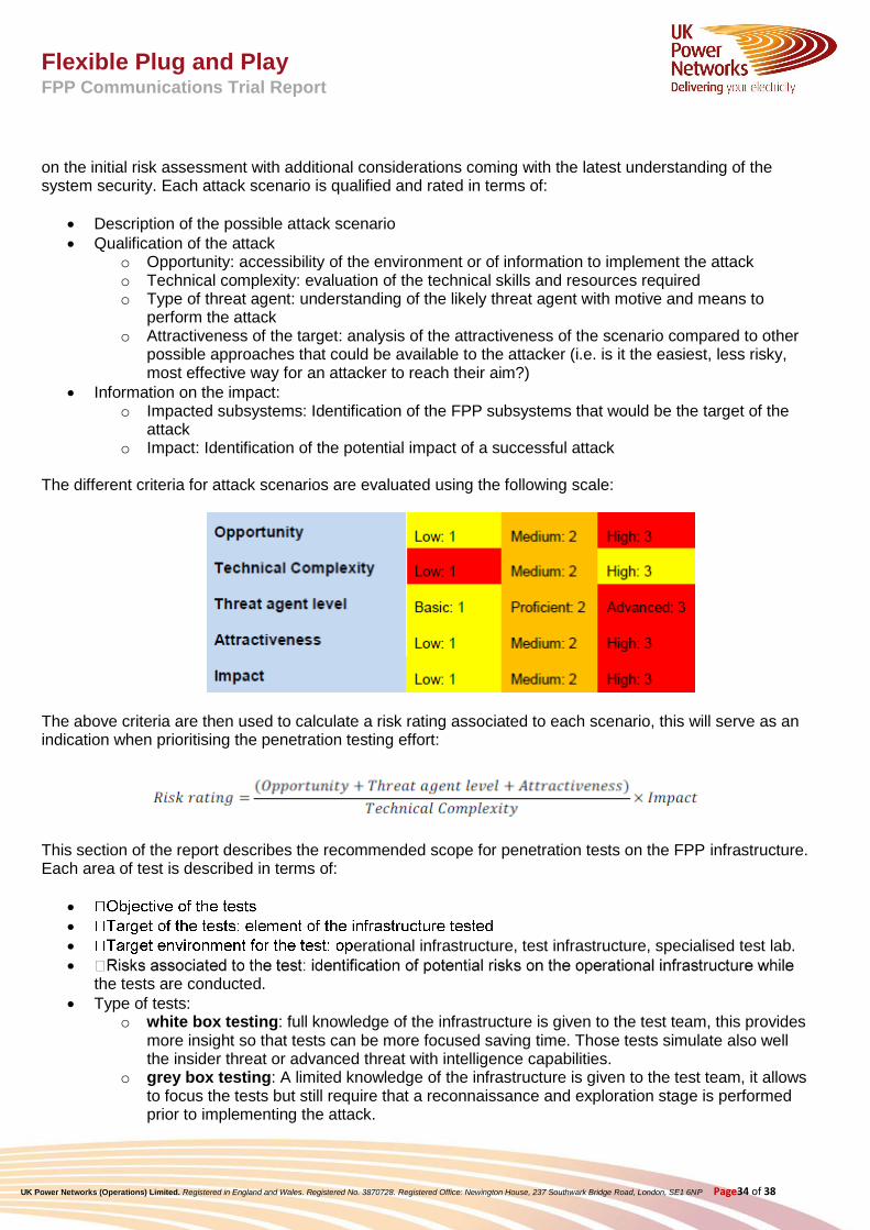
on the initial risk assessment with additional considerations coming with the latest understanding of the system security. Each attack scenario is qualified and rated in terms of:
Description of the possible attack scenario
Qualification of the attack o Opportunity: accessibility of the environment or of information to implement the attack o Technical complexity: evaluation of the technical skills and resources required o Type of threat agent: understanding of the likely threat agent with motive and means to
perform the attack o Attractiveness of the target: analysis of the attractiveness of the scenario compared to other
possible approaches that could be available to the attacker (i.e. is it the easiest, less risky, most effective way for an attacker to reach their aim?)
Information on the impact: o Impacted subsystems: Identification of the FPP subsystems that would be the target of the
attack o Impact: Identification of the potential impact of a successful attack
The different criteria for attack scenarios are evaluated using the following scale:
The above criteria are then used to calculate a risk rating associated to each scenario, this will serve as an indication when prioritising the penetration testing effort:
This section of the report describes the recommended scope for penetration tests on the FPP infrastructure. Each area of test is described in terms of:
erational infrastructure, test infrastructure, specialised test lab.
the tests are conducted.
Type of tests: o white box testing: full knowledge of the infrastructure is given to the test team, this provides
more insight so that tests can be more focused saving time. Those tests simulate also well the insider threat or advanced threat with intelligence capabilities.
o grey box testing: A limited knowledge of the infrastructure is given to the test team, it allows to focus the tests but still require that a reconnaissance and exploration stage is performed prior to implementing the attack.
Flexible Plug and Play FPP Communications Trial Report
UK Power Networks (Operations) Limited. Registered in England and Wales. Registered No. 3870728. Registered Office: Newington House, 237 Southwark Bridge Road, London, SE1 6NP Page35 of 38
o black box testing: No prior information is given to the test team, this simulates an external attacker with no knowledge of the infrastructure. It requires dedicating time to reconnaissance and exploration of the target prior to implementing any attack.
Finally, the tests are ranked in a recommended order of priority for UKPN considering:
learning points for UKPN,
ty associated to organizing the tests (e.g. involvement of third parties, risks of disruption of BAU operations).
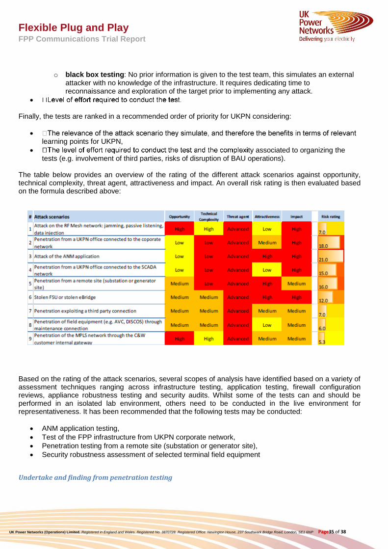
The table below provides an overview of the rating of the different attack scenarios against opportunity, technical complexity, threat agent, attractiveness and impact. An overall risk rating is then evaluated based on the formula described above:
Based on the rating of the attack scenarios, several scopes of analysis have identified based on a variety of assessment techniques ranging across infrastructure testing, application testing, firewall configuration reviews, appliance robustness testing and security audits. Whilst some of the tests can and should be performed in an isolated lab environment, others need to be conducted in the live environment for representativeness. It has been recommended that the following tests may be conducted:
ANM application testing,
Test of the FPP infrastructure from UKPN corporate network,
Penetration testing from a remote site (substation or generator site),
Security robustness assessment of selected terminal field equipment
Undertake and finding from penetration testing

Flexible Plug and Play FPP Communications Trial Report
UK Power Networks (Operations) Limited. Registered in England and Wales. Registered No. 3870728. Registered Office: Newington House, 237 Southwark Bridge Road, London, SE1 6NP Page36 of 38
External security experts were used by the FPP project to carry out penetration testing on the network. The worst case scenario was simulated where a hacker has the knowledge of the local and remote IP addresses and has managed to gain physical access to connect the local substation LAN. The type of the tests were selected such that these would target the high priority risks resulting from the risk assessment of the FPP overall architecture. This approach contributes to a proportionate management of risks and ongoing monitoring of operational risks linked to cybersecurity. During the future operational phase of the project, further tests may be conducted as required to explore other relevant attack vectors (e.g. advanced testing on RF Mesh network, test of robustness of the Secured Field Service Unit). The Penetration testers found that the security of the data from the substation to the pre-production ANM server was of a very good level with the correct provisions implemented. The Penetration testers visited the substation located in March, Cambridgeshire on 23 December 2014 to conduct the security assessment. The Penetration testers were provided with an spare IP address, subnet mask and the default gateway for their test laptop to be configured and was allowed to plug into the local FPP substation LAN at March Grid substation. The IP address of the pre-production ANM server was also provided along with two ports that should be expected to be open. These ports were TCP 102 and TCP 5001. Apart from the open ports, The Penetration testers were informed that ICMP Ping traffic was also permitted. Once connected to the network, an initial reconnaissance scan of the local subnet was conducted to identify hosts. This scan revealed six other hosts. Following this a full port scan of the first notified default gateway was conducted which was one of the smart devices with a remote 3G access from the vendors . The host had a number of interesting ports/services identified. The port of most interest on this host was the SSH port, to which a brute-force attack was conducted using the most common username and password combinations to gain access to the device. However, authentication to the device was not successful through this method as shown in the following screenshot.
The Penetration testers did not perform a full port scan on all hosts within the subnet due to the fragile nature of the devices in use, rather performing port scans on individual hosts.
The second test was performed with the default gateway IP address as the RF mesh remote Ebridge. This gateway IP address was then scanned to find that only one port was open, port 6543. After a Telnet connection was established to the service it was found that it did not require authentication, although it appeared that the commands available on the device were limited.

Flexible Plug and Play FPP Communications Trial Report
UK Power Networks (Operations) Limited. Registered in England and Wales. Registered No. 3870728. Registered Office: Newington House, 237 Southwark Bridge Road, London, SE1 6NP Page37 of 38
Several attempts using different methods such as ICMP requests and TCP port probes were performed against the IP address of the pre-production ANM server. All attempts were found to be unsuccessful, meaning that the host was not accessible from an unauthenticated user perspective. PA Consulting Group was later informed that there were restrictions implemented, to ensure that only users whose MAC addresses that had been registered with a server hosted in the United States would be able to access this. As a result of the testing conducted it would appear that the configuration of this filtering method successfully prevents unauthorised hosts from accessing the remote server.

Flexible Plug and Play FPP Communications Trial Report
UK Power Networks (Operations) Limited. Registered in England and Wales. Registered No. 3870728. Registered Office: Newington House, 237 Southwark Bridge Road, London, SE1 6NP Page38 of 38
8.0 Communication Trial Outcomes
The Communication trial allowed getting a better understanding of the implementation of radio mesh network for smart grid Communications and the capabilities of such an approach. The trial has highlighted that the RF mesh infrastructure with the canopy approach was a scalable solution facilitating the process of connection of new communications points in the FPP trial area. This process has been used by the business (operational telecom team of UKPN) during the FPP implementation and the knowledge captured during this stage will enable efficient future FPP solution deployment as well as facilitate the potential utilisation of the RF mesh technology for future applications The trial proved that the communications network was able to support multiple and concurrent flow of IP based open standards such as protocol IEC 61850, SNTP and DNP3, demonstrating that interoperability and multiple IP based protocols are concurrently supported over the network of wide geographic area.
The trial activities focused to illustrate that the newly deployed RF mesh communications was highly secure supported by enhanced security monitoring and management facilities implemented as part of the FPP communication infrastructure. In addition to the security deployment the requirements for penetration testing has been also considered by UKPN as part of the trial phase of the FPP project in order to support the cyber security approach. The objectives of the penetration tests were to acquire an understanding and exploration of potential weak points in the systems and to identify potential areas of residual vulnerabilities.
Finally the communication trial investigated the performance of the communications solution based the RF mesh infrastructure and its ability of supporting the communications required by the FPP technical solution. The capability of the whole ANM solution including both the central system and the field device was tested and proven to identify a communications failure; take fail safe action and quickly restore the system to normal operation once the system becomes healthy.
Availability of the communications platform was found to be the highest priority performance indicator for the deployment of ANM system. One of the attributes of the RF mesh network is the self-healing mechanism which provides multiple routes back to the destination in event of a node failure, improving the availability and resilience of the network. However, it was seen that the overall communication architecture needed to be optimally designed and thoroughly tested including the WAN architecture as the trial results demonstrated that the network can be as strong as its weakest link. Throughput and latency were also other important parameters affecting the performance of the overall ANM system. The FPP communication platform following performance results were seen:
• Availability: Even though both the WAN and the RF mesh availability was individually seen to attain over 99% performance levels, the end to end network suffered intermittent outages. This seriously impacted the overall network availability performance levels.
• Throughput: It can vary from >200kbps to <20kbps depending on the device with number of hops to the master node and link quality
• Latency: Multiple factors affect latency – number of RF mesh hops, Routing via different master node.
The trial highlighted that the quality of actions taken by ANM during abnormal events is also crucial to maintaining quality of supply and protecting the health of distribution assets and equally in maximising the export of the DG power to the network.