Embed Size (px)
Citation preview

| 1
Flexible Plug and PlayA demonstration of the technical characteristicsof the Flexible Plug and Play solution - SDRC 9.4
September 2013

Definitions
Active Network Management (ANM) Autonomous, software-based control system that monitors grid conditions and issues
instructions to distributed generators or other field devices in order to maintain the
distribution network within operating limits.
Automatic Voltage Control (AVC) Substation level system that is used to maintain the substation voltage at a constant
value and within the statutory limits.
Combined Heat and Power (CHP) Co-generation or use of power plant to simultaneously generate electricity and
useful heat.
Communications platform The communications platform installed and commissioned in the FPP trial in March
2013. It is based on the Radio Frequency wireless mesh technology.
CDM Construction, Design and Management 2007: regulations used in the construction
industry in UK.
DigSILENT Manufacturer of PowerFactory – a power systems modelling tool used by
UK Power Networks.
Distributed Generation (DG) Electricity generation connected to the distribution network.
Distributed Network Protocol (DNP3) Communication protocol widely used currently in the utilities industry.
Dynamic line rating System for calculating real-time ratings of overhead lines based on actual
weather data.
EPN Eastern Power Networks plc, the holder of a distribution licence.
ENMAC The system that UK Power Networks is using at Control Centre level to manage its
distribution network.
FPP Trial Zone An area of the EPN distribution network that serves approximately 30km diameter
(700km2) between Peterborough and Cambridge in the East of England, UK.
IEC 61850 The International Electrotechnical Committee’s Standard for the design of electrical
substation automation.
Term Description

| 3
Local Area Network (LAN) Group of computers and associated devices that share a common communications line.
Low Carbon Network Fund (LCNF) A funding mechanism introduced by Ofgem to promote projects that will help all
DNOs understand how they can provide security of supply at value for money as
Britain moves to a low carbon economy.
Modern Protection Relays or A protection scheme to be trialled by the FPP project to overcome the limitations
Novel Protection scheme associated with the use Directional Overcurrent schemes for protection of Grid
transformers.
Ofgem The Office of Gas and Electricity Markets: regulator for the electricity and gas markets
in Great Britain.
On load tap changer A connection point selection mechanism along a power transformer winding that
allows a variable number of turns to be selected in discrete steps.
Point of connection The interface between the UK Power Networks’ equipment (main fuse, energy
meter) and the consumer’s equipment (supply panel).
Quadrature-booster A specialised form of transformer used to control the flow of real power on a three-
phase electricity transmission network.
SCADA Supervisory Control and Data Acquisition: centralised computed-based systems that
monitor and control the electricity distribution network.
Standard Running Arrangements The distribution network configuration under normal network operating conditions.
PI – Data Historian The IT system UK Power Networks is using for collection and archiving of real-time
data and events, mainly measurements from the distribution network.
SNTP (Simple Network Time Protocol) A networking protocol for clock synchronization between computer systems.
Term Description

Flexible Plug and Play A demonstration of the technical characteristics of the Flexible Plug and Play solution
4 |
Contents Definitions 2
1 Executive Summary 6
2 Introduction 8
2.1 Flexible Plug and Play 9
2.2 Flexible Plug and Play: The Trial Zone 10
2.3 Scope of report 11
3 Assumptions and Design Approach 12
3.1 DG Connections and constraints location 13
3.2 FPP technical solution 15
3.3 Learning from the integration process 23
and results
4 Data Communications 24
4.1 Concept 25
4.2 Design 26
4.3 Data optimisation 31
5 Smart Devices 34
5.1 Quadrature-booster and Quadrature-booster 36
Controller System (QBCS)
5.2 Dynamic line rating 38
5.3 Automatic Voltage Controller (AVC) 40
5.4 Remote Terminal Unit 42
5.5 Novel protection relays 45
5.6 Ring Main Units for network reconfiguration 47
6 Smart Applications 48
6.1 Design 50
6.2 Testing and commissioning 55
7 Next steps 57
8 Appendices 59
FiguresFigure 1: Physical architecture 16
Figure 2: Communications architecture 17
Figure 3: FPP integration platform 21
Figure 4: Data engineering process 28
for RTU configuration
Figure 5: Data traffic and DG connections 32
Figure 6: Dynamic line rating 39
architecture diagram
Figure 7: Simplified SuperTAPP n+ Connection 40
Figure 8: General ANM architecture 51
Figure 9: Communication with external 52
applications
Figure 10: ANM production platform for 54
site acceptance test
TablesTable 1: FPP baseline solution 19
Table 2: IEC 61850 integration tools 22
Table 3: IEC 61850 conformance blocks for FPP 29
Table 4: FPP data usage estimation 31

| 5
1Executive Summary

Flexible Plug and Play A demonstration of the technical characteristics of the Flexible Plug and Play solution
6 |
Executive SummaryThe focus of this report is the design and deployment of the
smart devices and their integration with the ANM system to
a fully operational FPP solution that delivers the specified
functionality. This is an important milestone for the FPP project
as it marks the completion of its construction phase and start
of the trials phase. During trials, the ability of the technical
solution to release headroom in the network and facilitate the
faster and cheaper connection of DG will be tested.
Two DG customers have accepted the FPP connection
offers and their wind farms are planned for connection to
the distribution network in July 2014. Working with real
customers will generate significant learning for the project
but the project has also been designed so that the technical
solution can be tested through simulation in order to de-risk
any potential issues with customer recruitment.
The various components of the technical solution were
supplied by different project partners:
• Smarter Grid Solutions designed, installed and
commissioned the ANM system that will be used to control
generator output;
• Fundamentals Ltd delivered the Quadrature-booster
Controller and the Automatic Voltage Controller relays;
• Alstom Grid provided the novel protection scheme to
overcome the limitations associated with the use of
Directional Overcurrent (DOC) protection and the DLR
solution for 33kV overhead lines; and
• GE Power Conversion has developed the upgraded Remote
Terminal Unit for the substations located into the trial area.
One of the main objectives of the project was to develop
the FPP technical solution on an open standard architecture
using the IEC 61850 substations communication standard for
the integration of the ANM system and the smart devices.
The specific standard was chosen in order to gain experience
Flexible Plug and Play (FPP) is a Second Tier Low Carbon
Network Fund (LCNF) project that aims to connect distributed
generation (DG) onto constrained parts of the electricity
distribution network without the need for conventional
network reinforcement. To achieve this, innovative technical
and commercial solutions are being trialled to manage
constraints and maximise network utilisation.
TheFPPtechnicalsolutionisbasedonthreemain
components:
1. A communications infrastructure to facilitate integrated
operation of the geographically disparate components
that make up the FPP technical solution. The design and
commissioning of the communication infrastructure has
been a key milestone for the project and was completed in
March 20131.
2. Power systems devices in the field (also referred
to as “smart devices”) which are connected to the
communication infrastructure and which provide control
and monitoring capabilities. One of these devices is the
Quadrature-booster which was commissioned in July 20132.
Other devices are the Dynamic Line Rating (DLR) system
for 33kV overhead lines, the novel protection relays, the
upgraded Remote Terminal Units (RTU), the Generator
Controllers and the Automatic Voltage Control (AVC) Relays.
These devices are deployed as point solutions that resolve
local constraints and release additional headroom in the
existing infrastructure for connection of DG.
3. A centralised Active Network Management (ANM) system
which provides overarching management of the various
functional and controllable elements that make up the FPP
technical solution; The ANM system enables the overall
integration of the various point solutions into a coordinated
system approach.
1 SDRC 9.3 - Communications Platform report, available at www.flexibleplugandplay.co.uk 2 SDRC 9.8 – Deployment of Quadrature-Booster within the trial area report, available at www.flexibleplugandplay.co.uk

Flexible Plug and Play A demonstration of the technical characteristics of the Flexible Plug and Play solution
| 7
with its use and explore whether its engineering structure
and definition could ease integration and reduce engineering
time for applications in smart grid projects.
The project achieved its main milestone of commissioning
the FPP solution while pushing the boundaries of technical
and organisational innovation in a number of areas including:
TheDNOasthesystemintegrator
The FPP project involves significant information and
communication technology elements to solve power systems
problems. The relevant work activities associated with the
delivery of the technical solutions were structured in four
distinct work packages:
• Workstream 1 Delivery of the Communications
Infrastructure
• Workstream 2 Delivery of the Smart Devices
• Workstream 4 Delivery of the Active Network
Management system
• Workstream 8 Systems Integration
The Systems Integration workstream working closely with the
Technical Design Authority function ensured an integrated
approach and process in designing and testing the systems
installed. The testing approach involved different stages
of testing including a pre-production integration platform
which was used to test all components and prove their
interoperability before commissioning in the live operational
distribution network.
UK Power Networks’ subject matter experts from a number
of departments including Information Systems, Operational
Telecommunications, Asset Management and the FPP project
teams worked together with external input where required
to design, install and test the systems.
The project at its inception decided to keep in-house the
majority of the Systems Integration work in order to develop
skills and retain a significant proportion of the knowledge
generated.
ImplementationofIEC61850substationcommunications
protocol
The project has delivered the open standards architecture by
implementing a data communication infrastructure using the
IEC 61850 standard. The IEC 61850 standard is widely used
inside the boundary of the individual electrical substation
boundaries for protection scheme applications; however
the project is using it in a novel way both in terms of
communication between multiple substations and also over
a wireless mesh network.
The novel approach in the use of the standard meant that
key challenges such as data and traffic optimisation had
to be tackled generating significant learning and providing
an initial understanding on the potential for scalability and
application of such technologies.
This report outlines the design, testing, installation and
commissioning of the FPP technical solution and it marks
the successful completion of the Successful Delivery Reward
Criterion (SDRC) for the Demonstration of FPP technical
characteristics of FPP solution referenced as 9.4 in the Project
Direction.
The FPP project intends to disseminate further information on
the learning outcomes and performance of the FPP technical
solution during the trial phase of the project.

Introduction
2

Flexible Plug and Play A demonstration of the technical characteristics of the Flexible Plug and Play solution
| 9
Flexible Plug and Play (FPP)2.1The FPP project, funded under Ofgem’s LCNF Second Tier
mechanism, aims to facilitate the faster and cheaper
connection of DG onto the distribution electricity network
without the need for conventional network reinforcement.
The FPP methods achieve this objective by managing network
constraints and maximising network utilisation, which will be
conducted through the integration of smart devices, smart
applications and smart commercial arrangements.
The project, led by UK Power Networks, addresses this
requirement in partnership with ten project partners:
Vodafone (formally Cable & Wireless Worldwide), Silver
Spring Networks, Alstom Grid, Smarter Grid Solutions, GL
Garrad Hassan, University of Cambridge, Imperial College
London, the Institution of Engineering and Technology,
Fundamentals Ltd and GE Power Conversion.

Flexible Plug and Play A demonstration of the technical characteristics of the Flexible Plug and Play solution
10 |
Flexible Plug and Play: The trial zone2.2The location chosen for the FPP project is an area of
UK Power Networks’ EPN distribution network that
serves approximately 30km diameter (700km²) between
Peterborough and Cambridge (the FPP Trial Zone) in the East
of England, UK. This area is favourable to DG developers,
wind and solar farms in particular, due to geography and
favourable weather conditions3.
Over recent years UK Power Networks has experienced
increased activity in DG development in this area, and a
rapid rise in connection applications; existing renewable
DG connections total 144MW, with 158MW of DG capacity
currently at various stages of the planning process seeking
to connect as at July 2013. Using conventional connection
approaches, the connection of this anticipated growth in
DG is expected to require significant network reinforcement
to manage network thermal and voltage constraints and
reverse power flow issues.
For this reason, the area between Peterborough and
Cambridge serves as an ideal trial area for the FPP project to
explore alternative smart connection solutions.
An extensive set of trials aligned with the project’s use cases
will run from Q3 2013 to Q4 2014 in order to generate key
learning outcomes that the project is seeking to deliver both
in terms of facilitating cheaper and faster connections and
the performance of the overall technical solution that has
been installed.
3 http://www.ukpowernetworks.co.uk/internet/en/connections/documents/HQ-2000-4702-D.pdf

Flexible Plug and Play A demonstration of the technical characteristics of the Flexible Plug and Play solution
| 11
Scope of report2.3This report summarises the work associated with the design
and deployment of the FPP technical solution and the
completion of SDRC 9.4 (A Demonstration of the Flexible
Plug and Play technical characteristics of the FPP technical
solution) by end of September 2013 as described in the FPP
Project Direction. The successful completion of the SDRC is
evidenced by the commissioning of the different components
of the architecture and this report, a catalogue of available
evidence can be found in Appendix 5.
In addition, this report provides an initial insight to the learning
available to other Great Britain distribution network operators
when designing, installing and commissioning similar systems
and gives an indication of the learning that will be generated
by the project during the trials phase (Q4 2013 to Q4 2014).
Thereportisstructuredasfollows:
Section3 Outlines the design approach that has driven
the specifications of the technical solution and
describes the strategy to ensure the integration
of the overall FPP solution.
Section4 Provides the key elements considered for the data
communication design and implementation.
Section5 Details the overall process going from the
requirements and specifications up to the final
commissioning on site for all the smart devices.
Section6 Focuses on the smart applications. The section
highlights the specifications retained for the
implementation of the ANM system and the
process driven to the acceptance of the solution.
Section7 Concludes the report and highlights the main
learning.
Appendix5summarisesthekeydocumentsavailablethat
evidencetheSDRCrequirementsaslistedbelow:
• Installation and commissioning documentation of IEDs and
other field devices necessary to support the trials and in
accordance with the specification included in the contracts
with the relevant partners.
• Installation and commissioning documentation of production
of smart applications in accordance with the specification
included in the contracts with the relevant partners.
• Pre-production interoperability test results for FPP’s smart
devices and smart applications.
• IEC 61850 certification for all relevant Remote Terminal Units
(RTU), Intelligent Electrical Devices (IED) and other IEC 61850
field devices.
A list of the key project documents generated during
completion of this work that are available to GB DNOs is
included in Appendix 6.

3Assumptions and Design Approach

Flexible Plug and Play A demonstration of the technical characteristics of the Flexible Plug and Play solution
| 13
DG connections and constraints location3.1As of July 2013, the potential for renewable generation in
the trial area is approximately at 302MW of capacity and
consists of 144MW of connected DG and a further 158MW of
DG capacity at various stages within the connections process.
The size of the projects varies from 0.25MW up to the largest
at 18.5MW, all of which are proposed for connection in the
11kV, 33kV and 132kV distribution network.
Theconnectionofthesegeneratorswillcausespecific
issuesthathavebeenidentifiedincluding:
• Thermalconstraints: Thermal overloads arising at certain
pinch points, partly due to the natural flow of power
through the interconnected network, which leaves some
capacity under utilised.
• Increaseinreversepowerflows: Existing Grid substation
transformers have limits on reverse power flow, which
is due to the allowable Directional Overcurrent (DOC)
protection settings and the size of the Grid transformers.
• Voltageconstraints: Voltage control is made more difficult
by the changes in power flows, particularly reverse power
flow through tap changer transformers. The connection
of DG on the 11kV side at primary substations may cause
voltage levels to be outside of statutory limits.
Appendix 1 presents a simplified single line diagram for
the FPP trial area including all the DG connections and the
constraint locations described below. The generators are
categorised as those that currently connected, those that have
accepted their connection offers and those that are at different
stages of planning and might materialise in the future.
3.1.1ConnectionsfeedingintoMarchGrid(reverse
powerflows)
Any connections within this area of the network, at any voltage
(EHV, HV or LV), would increase reverse power flow from 33kV to
the upstream 132kV network. The existing infrastructure within
the FPP project area consists of a small number of 132kV grid
supply points and an interconnected 33kV network supplying
small 33/11kV primary substations. The main limitation
on March Grid is the reverse power capacity, considerably
before the grid transformer reaches its thermal or tap change
capabilities, which is limited by the maximum settings that
can be applied to the Directional Overcurrent (DOC) protection.
The present limitations are 2 x 45MVA transformers, maximum
DOC setting 75% x 45MA = 34MVA under N-1 condition when
one of the grid transformer circuit is out of service. Although
some additional spare capacity could be released through
the replacement of the existing protection system, this would
only provide a further approximately 11MW of headroom
which, when compared to an aggregated total of 19.75MW of
requested exports and the potential for increases in the uptake
of small scale generation, it would quickly be exceeded.
The first of the FPP accepted offers (a wind farm of 10MW
capacity) will connect in the area of March Grid utilising the ANM
technology in order to manage the reverse power flow constraint.
The connection is planned for energisation in summer 2014.
3.1.2ConnectionsintoPeterboroughCentralGrid(reverse
powerflows)
Any connections within this area of the network, at any
voltage (EHV, HV or LV), would reduce load at Peterborough
Grid 33kV, and therefore increase reverse power flow from
33kV to the upstream 132kV network. The main limitation on
Peterborough Central Grid is the reverse power capacity, well
before the grid transformer reaches its thermal or tap change
capabilities, which is limited by the maximum settings that
can be applied to the Directional Overcurrent protection. The
present limitations are 2 x 60MVA grid transformers, maximum
DOC setting 75% x 60MA = 42MVA under N-1 condition when
one of the grid transformer circuit is out of service. The projected
worst- case reverse power flow with the existing generation
is approximately 13MW. Whilst the spare capacity is currently
32MW, there is a further 30.9MW of aggregated generation

Flexible Plug and Play A demonstration of the technical characteristics of the Flexible Plug and Play solution
14 |
accepting additional DG onto the distribution network.
3.1.6ConnectionsontoMarchPrimary(voltagerise)
The high penetration of DG around the March Grid significantly
changes behaviour of the distribution network around that area.
High volumes of generation connecting on the network affects
the voltage profile on the distribution network, and possible
unacceptable voltage rise at the point of common coupling (PCC).
Like other distribution networks, the original design does not
consider bi-directional power flows, voltage rise contributions
from DG, and other associated impacts. As a result standard
voltage regulation strategies are unable to satisfactorily deal
with these problems. Therefore, novel solutions are required.
3.1.7ConnectionsontoChatterisPrimary(voltagerise)
Voltage level studies show possible fluctuations when
distributed generators are connected. When planned
generators are connected the indicative voltage rise at
Chatteris 11kV is 1.043pu, which is close to the 6% limit, and
leaves little headroom for the connection of further DG.
3.1.8ConnectionsontoNorthwoldandDownhamMarket
33kVlines(thermal–powerflowbalance)
The 33kV Northwold overhead line and the 33kV Downham
Market overhead line operate in parallel with differing source
impedances resulting in unbalanced load sharing. The full capacity
of all the lines cannot be used because Northwold reaches its
full capacity limit when the other line is at two thirds of its fully
capacity. This is a common constraint where the 33kV network runs
interconnected. This constraint restricts the seasonal export of the
local CHP plant at Wissington British Sugar factory, and constrains
connection of additional generation along the Downham Market
line. To increase utilisation of the 33kV line capacities out of
Wissington, the parallel circuits required to be augmented with
series-connected impedance addition/reduction capabilities.
The added (or compensated) impedance is chosen such that the
power flow balance between the parallel lines is improved.
expected to be connected in the area, along with the potential
for increases in the uptake of small scale generation.
3.1.3ConnectionsontoBury–PeterboroughCentral33kV
circuit(thermal)
This zone involves a 20.7km overhead line through areas around
Bury, Farcet and Ramsey. Any connections within the area on
the 33kV network, especially between Bury Primary and Farcet
Primary where the conductor is smallest, would increase thermal
loading on this circuit beyond its limits (23MW summer rating).
One of the two accepted FPP connections (wind farm, 7.2MW
capacity) will utilise this line and the constraint will be
managed through a combination of application of dynamic
line rating and ANM technology. The connection is currently
planned for energisation in Q2 2014.
3.1.4ConnectionsbetweenMarch/ChatterisT2Teepoint–
FunthamsLaneT233kVOHLcircuit(thermal)
There is a dense distribution of wind farms connected to this
overhead line (OHL), which currently forms a bottleneck for
the connection of further DG in the area as the current capacity
is near the thermal rating of the overhead line conductor.
3.1.5ConnectionsbetweenMarchGrid–WhittleseyT2/
ChatterisT233kVcircuit(thermal)
This section of network comprises of 5.06km overhead line
conductor all rated 23MW (summer). This rating is based on
static seasonal ratings traditionally applied to overhead lines –
summer, autumn/spring and winter which are based on ENA
Engineering Recommendation (ER) P27. A total of 10.75MW of
firm generation export has already been connected on this line,
with a further 17.5MW of generation requesting connection.
This would increase the loading to 28.25MW, which exceeds the
23MW summer capacity rating of the line. This and any further
connections would therefore impact on the thermal loading
of this 33kV circuit and its capacity would form a constraint in

Flexible Plug and Play A demonstration of the technical characteristics of the Flexible Plug and Play solution
| 15
FPP technical solution3.23.2.1OverviewoftheFPPtechnicalsolution
In context of the above constraint scenarios a technical solution
is required to enable a seamless integration of new distributed
generators within the trial area with an autonomous and real
time management of those network constraints. The technical
solution, comprising of a range of solutions, is designed to cater
for single or combination of constraints at a single location and
is able to evolve and adapt to changes in network conditions
caused by addition of new generators.
The technical solution involves the implementation of a smart
grid architecture using smart devices and ANM over an Internet-
Protocol (IP)-enabled communications backbone, in parallel
with UK Power Networks’ existing Supervisory Control and Data
Acquisition (SCADA) and related communications infrastructure.
The FPP project is seeking to prove that the technical solutions
can work together to deliver their specified functionality and
should distributed generators are willing to connect during the
life time of the project then their faster and cheaper connection
can be facilitated.
In essence the function of the FPP technical solution is to actively
manage real and reactive power flows on the distribution
network in response to prevailing network conditions to
maximise generation output/export whilst ensuring that
dynamically calculated network constraints are not breached.
This may be achieved through a combination of distributed
autonomous control actions and centralised co-ordinated
control actions, including control of generator output.

Flexible Plug and Play A demonstration of the technical characteristics of the Flexible Plug and Play solution
16 |
Physical architecture
Figure 1 illustrates the physical architecture of the FPP technical
solution, highlighting the key physical elements of the solution.
The equipment installed at control level (ENMAC, Active
Network Management, ODS (Operational Data Store)/PI – see
definitions) comprises mainly of servers located in data centres.
The equipment that is located in substations or in the field, such
as RTUs, smart devices and local ANM controllers comprises
mainly of industrial computers. It also illustrates where existing
communications (legacy system) and new radio frequency
mesh wide area communication infrastructure will be used.
3.2.2 Architecture of the FPP technical solution
SCADA systems in the majority of power industries typically
operate in a centralised management model providing both
monitoring and control facilities. The FPP architecture has
adopted a similar model with a centralised ANM system
which interfaces with the existing UK Power Networks’ SCADA
system but operates independently at both functional and
non-functional levels. By the virtue of this model, every design
aspect ensures that no element of the FPP architecture will
interfere with the existing IT and SCADA infrastructure during
the FPP trial phase. The separation of the two infrastructures
was a key business requirement for the trial to ensure that the
new FPP systems have no impact on the business-as-usual
operation of the existing systems.
Figure 1: Physical architecture
ENMAC Active Network Management system ODS/PI
Generator/circuit breaker
Weather stationand CTs
Tap changerQuad booster
Novel Protection SchemeRTU in Local Control Unit
Ring Main Units
Existingmeasurements/Status of network
Quad Booster Control System Local ANM ControllerDynamic Line Rating Relay
Weather stationLeg
acy Co
mms
RF CommsRF Co
mms
RF C
omm
s
RF Comm
s
RF Comms
RF CommsRF Comm
s
Automatic Voltage Controller
Flexible Plug and Play Successful Reward Delivery Criteria 9.4 Report
UK Power Networks (Operations) Limited. Registered in England and Wales. Registered No. 3870728. Registered Office: Newington House, 237 Southwark Bridge Road, London, SE1 6NP Page18 of 55
The equipment used to form the integration platform (please refer to Figure 3 for the relevant schematic):
• ANM Pre-‐production platform • 3 RF mesh devices (2 remote E-‐bridges and 1 master E-‐bridge)
• 1 measurement simulator (OMICRON) • 1 computer to run IEC 61850 Integration tools (see next section) • 1 optical switch
Figure 3: FPP integration platform
Client/Server Simulator
Generator Controller Generator Controller
RF comms
Ethernet Switch
MastereBridge
Remote eBridge
Smart ApplicationsFront End
Generator Simulator
Optical/Ethernetswitch
RTU
Ethernet
Measurements Simulator
Wired
Ethernet Ethenet
Remote eBridge
RF comms
Ethernet
QBCS DLR AVC
Wired
Wired
Wired
Fibre Fibre
Fibre
Ethernet
ANM Pre-ProductionPlatfrom
ANM Pre-ProductionPlatfrom
RTU (Upgraded)
FPP high level architecture VO 3.vsd
FPP physical architecture 23/09/2013

Flexible Plug and Play A demonstration of the technical characteristics of the Flexible Plug and Play solution
| 17
Communications architecture
The second architectural diagram in Figure 2 provides view of
the entire communications architecture. This diagram presents
the architecture in three communications levels: operations
level (control centre), station level (substation) and bay level
(device) in order to categorise the functionality and location
of the components. The diagram also distinguishes between
existing and business as usual components as and new FPP
components using white background and yellow background
symbols respectively. This diagram also illustrates at a high level
the network connections between the various components
such as the connection of ANM system to UK Power Networks
applications at the operations level and interconnection of
substation devices at the station level.
Figure 2: Communications architecture
Substation LAN
UKPN RTU
RF ebridge
Ope
ratio
ns le
vel
Stat
ion
leve
lBa
y le
vel
ENMAC SCADA
VodafoneMSP WAN
Hardwired
Hardwired
Hardwired Hardwired
TEC (Telecontrol equipment cubicle)
UKPN RTU
ANM Local Controller TEC
MSP = Multi Services PlatformWAN = Wide Area Network
Digital data link
Substation LAN
HMIHMI
UKPN control centre
UKPN SCADA
FPP Silver SpringsRF Mesh
UKPN SCADA
RF ebridge
Plant measurements
Novel Protection
Relay
Quad BoosterControl System
Automatic Voltage Controller
Dynamic LineRating Relay
Generator control System
Customercircuit
breaker
UKPNcircuit
breaker
UKPNRTU
RFebridge
GeneratorController
PI Historian
ANM
Key
Fibre
CAT5e
Copper link/Hard wire
New FPP equipment
Existing equipment

Flexible Plug and Play A demonstration of the technical characteristics of the Flexible Plug and Play solution
18 |
3.2.3SmartDevicesandSmartApplications
TheFPPtechnicalsolutionconsistsofthefollowingkey
components:
SmartApplications:
• In order to keep the network within limits by controlling
interruptible distributed generators, two smart applications will
be trialled; one to manage to the power flows and the second
one to manage the voltage.
• A third smart application will also be trialled in order to provide
dynamic thermal rating of overhead lines at the central
application level.
SmartDevices:
• AQuadrature-boosterandQuadrature-boosterController
System (QBCS)4: The QBCS automatically controls the tap
position of the Quadrature-booster in order to manage power
flows in a parallel circuit. The ANM system is required to monitor
and control the generator output in order to optimise the flow
of power in the circuits, without conflict with the QBCS. The QBCS
will provide information to the ANM system, which will also use
measurements at Wissington substation to define optimal level
of generation output.
• DynamicLineRating(DLR): The function of the dynamic line
rating will be to monitor local weather station data and calculate
ampacity5 ratings based on the real weather conditions. The
ampacity ratings will be provided to the ANM system, which
will dynamically manage thermal constraints. According to the
generators and constraint locations.
• AutomaticVoltageController(AVC): The primary function
of the AVC will be to monitor the voltage level (11kV or 33kV)
by controlling the transformer On Load Tap Changer (OLTC) to
maintain voltages on the electrical network which it supplies
within appropriate/statutory limits. In the perspective of the
trial, two AVC schemes will be installed. They will monitor and
manage the voltage constraints that may occur mainly if new
generators will be connected on the 11kV grid. The devices will
also provide information the ANM system. The AVC devices are
delivered by Fundamentals.
• NovelProtectionRelays: The function of the novel protection
relay will be to trial alternative schemes to directional overcurrent
protection at specific locations within the FPP trial area, in order
to accommodate potential reverse power flows. The trials will
involve initial deployment of novel protection relays in an alarm
only configuration, in parallel with existing protection schemes.
The novel protection relay is delivered by Alstom Grid UK Ltd.
• UpgradedRTUs: The boundaries of the trial area are defined
by the electrical network feed by two Grid substations and
ten primary substations. These substations will be upgraded
to provide relevant measurements to the smart applications
using a standard protocol (IEC 61850). The upgraded RTUs are
delivered by GE Power Conversion.
Table 1 provides a summary of the equipment that has been
commissioned and makes up the FPP technical solution.
4 SDRC 9.8 – Deployment of Quadrature-Booster within the trial area report, available at www.flexibleplugandplay.co.uk 5 Ampacity is defined as the maximum amount of electrical current a conductor or device can carry

Flexible Plug and Play A demonstration of the technical characteristics of the Flexible Plug and Play solution
| 19
Table 1: FPP baseline solution
Power Flow Smart Application ANM UK Power Networks’ Control Centre
Voltage Smart Application ANM UK Power Networks’ Control Centre
Dynamic Rating Smart Application ANM UK Power Networks’ Control Centre
Generator Controllers (four) Generator substations
Quadrature-Booster Control System TapCON 260 relay (MR) Wissington substation
DLR1A and DLR1B Micom P341 relay (Alstom) Farcet Primary substation
M871 data logger
Lufft WS501-UMB compact weather station
DISCOS optical current sensors
DLR2 Micom P341 relay (Alstom) Funthams Lane Primary substation
M871 data logger
Lufft WS501-UMB compact weather station
DISCOS optical current sensors
DLR4 Micom P341 relay (Alstom) March Grid substation
M871 data logger
Lufft WS501-UMB compact weather station
AVC1 SuperTAPP n+ (Fundamentals) March Grid substation
AVC2 SuperTAPP n+ (Fundamentals) March Primary substation
MPR1 (Novel Protection Relays) Micom P142 relays (Alstom) March Grid
MPR2 (Novel Protection Relays) Micom P142 relays (Alstom) Peterborough Central
Upgraded substation RTUs (12) T5500 (GE) March Grid GS
Wissington
Farcet Primary
Peterborough Central GS
Chatteris Primary
Funthams Lane Primary
March Primary
Bury Primary
Littleport Primary
Northwold Primary
Whittlesey Primary
Southery Primary
FlexiblePlugandPlay Equipment CommissioningSitetechnicalsolution

Flexible Plug and Play A demonstration of the technical characteristics of the Flexible Plug and Play solution
20 |
TestingandintegrationapproachoftheFPPtechnical
solution
One of the main challenges of the project was the testing
and integration of various components into a functional and
scalable solution that delivers the project’s objectives. It was
recognised during the bid stage that the integration process
was a key risk for the project that could impact both the
quality of the technical solution and the delivery timescales.
In order to mitigate this, a comprehensive testing approach
was developed including different stages of testing and the
set-up of an integration laboratory in UK Power Networks’
premises where the interoperability testing could be carried
out prior to deployment into the live operational environment.
The responsibility for the testing and integration process
was shared between the FPP Workstream Managers,
FPP Project Manager and Design Authority. In addition,
UK Power Networks’ subject matter experts in specific areas
such as Real-Time Systems, Information Systems and Capital
Programme were engaged alongside specialised personnel
from the various project partners and suppliers in order to
carry out the various tests.
3.2.4Testinglevels
TheFPPprocessoftestingwasbasedonfollowing
approach:
1.Unittests: Unit testing is the first to take place; it does not
test the overall system but only partial parts that have been
developed separately. Each unit test case is independent
from the others. These unit tests may involve substitutes
like mock-up devices and test harnesses to assist testing
a product in isolation. Also some local integration tests
(related to software or devices) can be also done to prepare
the systems for integration testing. These tests include
technical and functional aspects.
2.Integrationandinteroperabilitytests: System integration
testing is the process that exercises a FPP product’s
coexistence with others. The system integration process
tested the FPP products required interactions with the whole
FPP solution. The FPP architecture uses a standard protocol for
data exchange; as such interoperability tests are part of the
integration tests.
All the integration tests are described into the System
Integration Test Specification document6. The system
integration testing involves:
• Data integration tests: These tests are designed to
demonstrate the interoperability of different components
implementing the same protocol. For that purpose, these
tests validate the communication between the IEC 61850
Client, the ANM servers, the IEC 61850 servers and smart
devices, under test over the proposed communication
channels for FPP. Data integration testing will not exercise
the full range of data exchange made possible by IEC 61850,
only the data exchange required by FPP will be tested.
• End-to-endfunctional: These tests exercised a subset of
the functionality set out in the FPP Functional Use Cases. The
integration testing can expose problems with the interfaces
among the system components before trouble occurs in real-
world system operation. At the interface the tests aimed to
validate the communication (RF Mesh) and the protocol (IEC
61850). The integration testing is completed progressively
until the entire system has been integrated. Once all the
integration testing in the laboratory is completed the site
acceptance tests are carried out to ensure the operation of
the system in a live environment.
Note: As part of the High Level Test Approach7 the test design also
describes the non-functional tests based on the non-functional
requirements as defined in the Functional and Non-functional
Requirement Specifications document8. Non-functional testing
6 DA P0250.FPP Scope of Work WS8 testing and system integration v1.07 DA.P0202.FPP High level Test Approach v1.08 DA.P0154.FPP Functional and Non-Functional Requirements Specification v1.0
Flexible Plug and Play A demonstration of the technical characteristics of the Flexible Plug and Play solution
| 21
can be done at different level of the testing strategy (during
unit, integration or acceptance tests) depending on the non-
functional requirement to test.
3.2.5 Testing environment
In order to deliver the testing planned, the different project
partners have setup their own test environments for unit testing
and for the factory acceptance test of the components they
were responsible for providing. As several components needed
to be implemented and integrated to provide the overall
FPP solution, the FPP project has setup its own independent
integration platform:
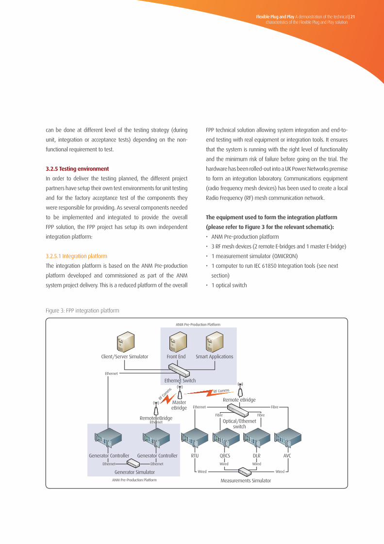
3.2.5.1 Integration platform
The integration platform is based on the ANM Pre-production
platform developed and commissioned as part of the ANM
system project delivery. This is a reduced platform of the overall
FPP technical solution allowing system integration and end-to-
end testing with real equipment or integration tools. It ensures
that the system is running with the right level of functionality
and the minimum risk of failure before going on the trial. The
hardware has been rolled-out into a UK Power Networks premise
to form an integration laboratory. Communications equipment
(radio frequency mesh devices) has been used to create a local
Radio Frequency (RF) mesh communication network.
The equipment used to form the integration platform
(please refer to Figure 3 for the relevant schematic):
• ANM Pre-production platform
• 3 RF mesh devices (2 remote E-bridges and 1 master E-bridge)
• 1 measurement simulator (OMICRON)
• 1 computer to run IEC 61850 Integration tools (see next
section)
• 1 optical switch
Figure 3: FPP integration platform
Flexible Plug and Play Successful Reward Delivery Criteria 9.4 Report
UK Power Networks (Operations) Limited. Registered in England and Wales. Registered No. 3870728. Registered Office: Newington House, 237 Southwark Bridge Road, London, SE1 6NP Page18 of 55
The equipment used to form the integration platform (please refer to Figure 3 for the relevant schematic):
• ANM Pre-‐production platform • 3 RF mesh devices (2 remote E-‐bridges and 1 master E-‐bridge)
• 1 measurement simulator (OMICRON) • 1 computer to run IEC 61850 Integration tools (see next section) • 1 optical switch
Figure 3: FPP integration platform
Client/Server Simulator
Generator Controller Generator Controller
RF comms
Ethernet Switch
MastereBridge
Remote eBridge
Smart ApplicationsFront End
Generator Simulator
Optical/Ethernetswitch
RTU
Ethernet
Measurements Simulator
Wired
Ethernet Ethenet
Remote eBridge
RF comms
Ethernet
QBCS DLR AVC
Wired
Wired
Wired
Fibre Fibre
Fibre
Ethernet
ANM Pre-ProductionPlatfrom
ANM Pre-ProductionPlatfrom
Client/Server Simulator Front End Smart Applications
MastereBridge
Measurements Simulator
Generator Simulator
Remote eBridgeEthernet
ANM Pre-Production Platform
ANM Pre-Production Platform
RF Co
mmsRF Comms
Ethernet
Ethernet
Remote eBridge
Fibre
Fibre
Wired
Fibre
Wired
Wired Wired
AVCRTU DLRQBCS
Flexible Plug and Play Successful Reward Delivery Criteria 9.4 Report
UK Power Networks (Operations) Limited. Registered in England and Wales. Registered No. 3870728. Registered Office: Newington House, 237 Southwark Bridge Road, London, SE1 6NP Page18 of 55
The equipment used to form the integration platform (please refer to Figure 3 for the relevant schematic):
• ANM Pre-‐production platform • 3 RF mesh devices (2 remote E-‐bridges and 1 master E-‐bridge)
• 1 measurement simulator (OMICRON) • 1 computer to run IEC 61850 Integration tools (see next section) • 1 optical switch
Figure 3: FPP integration platform
Client/Server Simulator
Generator Controller Generator Controller
RF comms
Ethernet Switch
MastereBridge
Remote eBridge
Smart ApplicationsFront End
Generator Simulator
Optical/Ethernetswitch
RTU
Ethernet
Measurements Simulator
Wired
Ethernet Ethenet
Remote eBridge
RF comms
Ethernet
QBCS DLR AVC
Wired
Wired
Wired
Fibre Fibre
Fibre
Ethernet
ANM Pre-ProductionPlatfrom
ANM Pre-ProductionPlatfrom
Optical/Ethernetswitch
EthernetEthernet
Generator ControllerGenerator Controller
Ethernet Switch

Flexible Plug and Play A demonstration of the technical characteristics of the Flexible Plug and Play solution
22 |
3.2.5.2 Integration tools
As part of the technical support on IEC 61850 implementation,
DNV KEMA was instructed to carry out an independent
evaluation and recommendation of data engineering, testing
and simulation tools. UK Power Networks’ internal stakeholders
were engaged in brainstorming workshop to identify core UK
Power Networks and FPP project requirements for the tools. A
requirement specification was subsequently created for each
tool which formed part of an information request to vendors
and essentially dictated the selection process. The following
tools were selected and procured for the FPP project.
These tools are used during the implementation of IEC 61850
in the project. Tool training was also organised for FPP team
members as well as relevant UK Power Networks’ staff likely
to be involved in future maintenance or implementation.
Further work will be carried out by FPP project team during
the trial phase to enable smooth business as usual handover
of these tools.
Table 2: IEC 61850 integration tools
1 Server Simulator Triangle Microworks ANVIL Simulates smart devices acting as IEC 61850 servers
2 Client Simulator Triangle Microworks HAMMER Simulates ANM acting as IEC 61850 client
3 Data Analyser KEMA UniCA Analyser Protocol analyser for error detection and
communications testing
4 Substation Configuration UniCA SCL Checker The SCL checker is used for validation of (SCL) files
Language (SCL) Checker
5 IED Capability Description Helinks STS The ICD Editor creates the ICD file used to configure
(ICD) Editor a server or a smart device
6 System Configurator Helinks STS The system configurator combines the ICD files into
one Substation Configuration Description (SCD)
file. This SCD file is imported in the Manufacturer
specific IED configurators.
No. IEC61850Tool SelectedProduct Function

Flexible Plug and Play A demonstration of the technical characteristics of the Flexible Plug and Play solution
| 23
Learning from the integrationprocess and results
3.3
The integration tests of the different components of the
FPP technical solution have required the team to manage
a large number of dependencies within the Project. Project
partners and project suppliers were involved in the delivery
of the smart applications and the Smart Devices. Using the
project plan, the FPP System Integration workstream setup
up the integration plan and identified the dependencies
with other workstreams. When the integration platform was
commissioned the integration process started with the aim
to integrate one by one the various elements of the FPP
technical solution. This process took six months to carry out
and three months before that to plan.
The challenge faced during this stage was the availability of
new skills to implement the IEC 61850 standard. To develop
new competencies, the project contracted technical support
and training. Specifically, DNV KEMA was engaged to provide
support with the design and implementation of the IEC 61850
project across the project. DNV KEMA worked very closely
with the rest of the FPP project participants and UK Power
Networks’ experts from the Information Systems, Operational
Telecommunications and Real-Time Systems teams.
It became evident that the integration of new generation
of relays and RTUs has changed with the introduction of
information and communication technologies within the
substation; operations that were traditionally the domain of
power systems engineers now could require additional skills
such understanding of IP networking, data communications
and data modelling.
In term of results, all the components of the FPP technical
solution have been successfully integrated following the
tests described into the System Integration Test Specification9
document. The results of these tests have been captured
by completing the test document and providing various
records (traces, logs and videos) in order to evidence the
pre-production interoperability test results for FPP’s smart
devices.
After the completion of the integration stage, the smart
devices and the smart application have been installed and
commissioned on site as detailed in the next sections.
9 WS08.P0142.FPP Integration Tests specification

4Data Communications

Flexible Plug and Play A demonstration of the technical characteristics of the Flexible Plug and Play solution
| 25
Concept4.1Data communication is an integral part of the FPP solution as
the FPP project concept relies on a system capable of real time
interaction between its components across wide geographic
area following innovative model of active management as
opposed to the traditional passive management. Essentially,
the core role of data communication in FPP is to enable
ANM to receive data relating to generator power export
and network constraint status so that any generator control
instructions from ANM can then be swiftly transmitted to
generator control system.
There are mainly three elements involved, communications
infrastructure, communications protocol and communications
equipment; the former two are detailed below and the latter
has been covered within various sections of this report.

Flexible Plug and Play A demonstration of the technical characteristics of the Flexible Plug and Play solution
26 |
Design4.24.2.1Communicationsinfrastructure
The FPP communications infrastructure is based on a multi-
layered architecture consisting of ANM Local Area Network
(LAN) at the operations level and substation LAN at the station
level, connected together by the FPP communications solution
comprising of RF Mesh Network and Wide Area Network
(WAN). The entire FPP infrastructure is capable of supporting
IP-based communications including IP-based protocols defined
by Distributed Network Protocol 3.0 (DNP3) and IEC 61850
standard. The communications infrastructure has been designed
to provide the highest degree of resilience and availability in line
with the standards of existing SCADA infrastructure particularly,
with consideration of design principles mentioned above.
RFMeshNetwork
In comparison to the widely implemented star or ring
topology in power industry, FPP project is implementing radio
communications mesh network topology which offers additional
benefits coupled with fresh challenges. The RF Mesh technology
acts as the primary connectivity between substations and the
end FPP generator sites, commonly known as the “last mile”
connection. The mesh network interfaces to FPP WAN via two
back-haul links presented at two grid substations providing dual
redundancy. The IP-based RF Mesh operates on sub-GHz radio
spectrum, 870-876 MHz, delivering the required propagation
and performance while supporting a practical data rate for
current and future smart grid services.
The mesh network is designed to provide radio canopy over
the FPP trial area thereby, making it easy to connect any future
generator customer. The mesh topology ensures that every
remote node always has multiple routes to a master node. One
of the fundamental differences to traditional network is that the
devices are able to communicate with each other in a peer-to-
peer fashion, without all communication passing through the
central firewalls adding another dimension to FPP security design
work. Further details on the RF mesh design and deployment
are given in FPP SDRC report 9.3 which is available on the FPP
website (www.flexibleplugandplay.co.uk).
WideAreaNetwork
RF mesh network utilises Vodafone Multi Service Platform (MSP)
to connect to the ANM LAN via two back-haul links. The MSP is
an IP-based network that provides a proven, secure and high
availability platform already in use as UK Power Networks’ core
communications IP backbone network. The WAN also enables
connectivity to Silver Spring Networks and Smarter Grid Solutions
via secure VPN (Virtual Private Network) tunnel connections.
Data traffic is logically segregated within the WAN using secure
sub-networks known as VRF (Virtual Routing and Forwarding).
Further details on the WAN design and deployment are given in
FPP SDRC report 9.3.
ANMLocalAreaNetwork
The ANM system is installed within UK Power Networks
Control Centre LAN in the form of a controlled sub-network
commonly known as DMZ (Demilitarised zone). With a firewall
separating the FPP network from the rest of UK Power Networks
infrastructure, DMZ provides additional layer of security. Over the
secured connection ANM exchanges data with SCADA servers,
PI Data Historian servers and the UK Power Networks Simple
Network Time Protocol (SNTP) time server.
SubstationLocalAreaNetwork
Similar to the concept of ANM LAN segregation at the Operations
level, FPP design also adopts similar approach at the station level
with implementation of FPP substation LAN. This serves two
primary functions; firstly to provide a medium for information
exchange between components of the FPP Technical Solution
which are co-located in the same substation; and secondly to
interface with RF mesh linking to the FPP WAN. There was no
standard in UK Power Networks for substation LAN, accordingly
the FPP project undertook extensive design work in this area

Flexible Plug and Play A demonstration of the technical characteristics of the Flexible Plug and Play solution
| 27
which aimed to provide technical reference for future projects.
Following key areas are covered as part of FPP substation LAN
design and implementation:
• LANTopology: Single switch star topology is implemented
which offers simplicity in design and maintenance.
• LAN switch implementation: Having assessed multiple
products against FPP requirement a Layer 3 Ethernet switch
is selected which supports multiple fibre and copper ports.
Wherever possible fibre cables are used for LAN connections
external to cabinets to mitigate issues from electromagnetic
interference.
• IP Addressing: FPP has implemented 27 bit subnet IP
addresses allowing 30 usable addresses for FPP devices in
each primary substation, a future-proofed approach that
would cater for significant amount of additional devices.
• Security: The substation LAN will be physically and logically
separate to other UK Power Networks’ network. It was
ensured that the LAN switch supports the security features
specified by the FPP security design requirements.
4.2.2Communicationprotocols
IEC61850FPPrequirements
The International Electrical Committee (IEC), representatives
from both utilities and suppliers have jointly elaborated the new
standard IEC 61850 “Communication Networks and Systems in
Substations”. Gaining acceptance worldwide, IEC 61850 is the first
and only global standard that considers all the communication
needs within substations.
The general scope of the standard is designed to support the
communication of all functions being performed in the substation.
Its main goal is interoperability; this is the ability for IEDs from one
or different manufacturers to exchange information and use the
information for their own functions. This point is very relevant
for the FPP context which aims to design an interoperable and
scalable solution able to cope with future requirements.
Although this protocol has been initially designed to implement
internal substation communication, the innovations brought by
the project are:
• To consider this protocol for communication between the
field devices and the centralised ANM server. The ANM
at the Control Centre will be acting as an IEC 61850 client
to communicate with the remote devices acting as IEC
61850 servers. The remote devices include substation RTUs,
Generator Controller and smart devices such as Dynamic Line
Rating relay, Quadrature-booster Control relay and Automatic
Voltage Controller.
• To implement IEC61850 protocol on a low bandwidth (when
compared to high bandwidth communications usually
available within the substation) communication medium such
as RF mesh.
For clarity, the FPP technical solution will use the following
elements of IEC 61850 standard communications as defined in
IEC 61850-8-1 part:
• Core Abstract Communication Server Interface (ACSI) services,
which are supported via Manufacturing Message Specification
(MMS) Protocol Suite support.
• Time synchronisation services, which are supported via SNTP
support.
As consequence, the use of Sampled Values (SV), Generic Object
Oriented Substation Events (GOOSE) and Generic Substation
State Events (GSSE) is out of scope of FPP.
IEC61850dataconfiguration
The data model of the IEC 61850 standard is an object-
oriented one, grouping the data into the smallest possible sets
referring to the smallest possible functions to be implemented
independently. These smallest possible data groups or functions
are named Logical Nodes. The Logical Nodes and all Data and
Attributes contained are named according to a standardised
semantic, which is mandatory.

Flexible Plug and Play A demonstration of the technical characteristics of the Flexible Plug and Play solution
28 |
A prerequisite for the project is the use of components, which are
proven to be compliant with IEC 61850. Each IED/Smart Devices
supplier provided a conformance test certificate for each device to
be used in the FPP solution.
In the IEC 61850 standard, all the files used to configure
compliant devices are written following a dedicated XML syntax:
the Substation Configuration description Language (SCL). In
order to document its data model each device is delivered with
a SCL file called IED Capability Description file (ICD). When the
devices are ready to be integrated into a system, the Configured
IED Description file (CID) describes all configuration parameters
relevant for that IED (IP address, Report Control Blocks). This file is
used as input to the ANM system (acting as an IEC 61850 Client)
to interact with the devices (acting as IEC 61850 Servers).
All the field devices used in the FPP solution, have been delivered
and tested with the appropriate ICD/CID files in order to be
integrated with the ANM system.
In the particular case of the FPP substation RTUs, which implement
an IEC 61850 Server, the capability is also described by a SCL file
of type .ICD which incorporates all of the relevant Logical Nodes
from the IEC 61850 data model in order to model the substation.
This is referred to as the RTU Master ICD file. The RTU Configuration
Tool will read this file and the user will select the required data
objects and associate them with internal RTU references (digitals,
analogs, alarms and controls).
The main activities were to identify the set of logical nodes
incorporating the ones required the FPP project, the ones that
could be defined as standard for UK Power Networks’ substations
and potential additional requirements for future applications. In
order to identify the overall requirements, the project engaged
with internal stakeholders. IEC 61850 training sessions and
workshops were carried out and will be carried out to disseminate
and develop IEC 61850 knowledge through operational teams.
The RTU Configuration Tool will output an SCL file of type .CID which
contains the configured IED information including the configuration
of data sets and report control blocks which the RTU uses to report
input data. The overall process is described in Figure 4.
Manufacturer
System Configurator
Master ICD
Updated Master ICD
*.ICDANM
4
1
1
2
3
4
FPP creates the Master .ICD with LN type templates
GE IED Configurator creates CID for specific substation with instantiated LN and LD from template
The specific CID is used by the System Configurator to create SCD for ANM system
TBD - in case of updating a Master LN type the CID be updated ‘easily’ with the new type
Specific.CID
GE IED Configurator
2
*.SCD
3
ICD Editor
Figure 4: Data engineering process for RTU configuration
*.ICD

Flexible Plug and Play A demonstration of the technical characteristics of the Flexible Plug and Play solution
| 29
IEC61850conformanceandcertification
One of the FPP project requirements is that any field device
using IEC 61850 protocol for the purpose of the project needs
to be certified. The IEC 61850 conformance blocks shown in
Table 3 have been identified to cover the FPP requirements.
The smart devices and applications were successfully
certified by independent third party assessors against the
FPP requirements.
Table 3: IEC 61850 conformance blocks for FPP
1: Basic Exchange Ass1, Ass2, Ass3, AssN2, AssN3, AssN6
AssN4, AssN5
Srv1, Srv2, Srv3, Srv4, Srv5, SrvN1abcd, SrvN4 Srv6, Srv7, Srv8, Srv9, Srv10, SrvN1e,
SrvN1f, SrvN2, SrvN3
2: Data Sets Dset1, Dset10a, DsetN1ae Dset10b, DsetN1b, DsetN16
5: Unbuffered Reporting Rp1, Rp2, Rp3, Rp4, Rp7, Rp10, Rp12 Rp5, Rp6, Rp8, Rp9, Rp11, RpN5,
RpN1, RpN2, RpN3, RpN4 RpN6, RpN7
6: Buffered Reporting Br1, Br2, Br3, Br4, Br7, Br8, Br9, Br12, Br14 Br5, Br6, Br10, Br11, Br13, BrN6, BrN7
BrN1, BrN2, BrN3, BrN4, BrN5
13: Time sync Tm1, Tm2, TmN1 Tm3, TmN2
ConformanceBlock Mandatorytestcases Conditionaltestcases

Flexible Plug and Play A demonstration of the technical characteristics of the Flexible Plug and Play solution
30 |
DNP3(DistributedNetworkProtocol)
DNP3 is also an open standard communications protocol
implemented for two applications in FPP project. In UK
Power Networks DNP3 is currently used by SCADA application
ENMAC to communicate with remote outstations or RTUs. As
ENMAC does not yet support IEC 61850 standard, ANM uses
the DNP3 protocol to communicate with it. In this case the
ANM acts as a DNP3 slave to ENMAC acting as a DNP3 master.
The second implementation of DNP3 in the FPP project is
at the substation level to communicate with optical Current
Transformer (CT) provided by Powersense. The optical CTs
are used to obtain current measurements for overhead lines
where CTs were not easily available. In this case the Optical
CTs act as a DNP3 slaves to the GE T5500 RTU which is acting
as a DNP3 master. This further demonstrates flexibility of the
FPP architecture by concurrently supporting existing and new
protocols at different levels.
SNTP(SimpleNetworkTimeProtocol)
Precise time clock synchronisation is an important requirement
for real time applications like ANM. Time synchronisation
provides common reference point for communicating devices
and allows accurate correlation of network events. As defined
in IEC 61850-8-1, SNTP is used for time synchronisation
in the FPP architecture for all communicating devices. At
operations level, the ANM system uses SNTP to synchronise
its time clock with the UK Power Networks’ master clock
at the control centre. However, this facility is not available
at the station level so, SNTP time server functionality was
developed within the GE T5500 RTU by the FPP project. The
RTU uses a local GPS receiver to maintain its internal time
clock and further allows FPP smart devices to subscribe to its
time service, that ensures that all system components and
measurements are time synchronised.

Flexible Plug and Play A demonstration of the technical characteristics of the Flexible Plug and Play solution
| 31
Data optimisation4.3The IEC 61850 standard was originally developed for internal
substation applications utilising high speed communications.
However, the FPP project is stretching the capabilities of the
standard by applying it over a wide geographic area over a
given bandwidth of a radio mesh technology. Hence, the data
communications need to be carefully optimised considering
the impact on the data loading on the radio mesh network
under the anticipated stress conditions such as communications
outage, disaster event, network congestion etc.
Initial lab tests carried out by Smarter Grid Solutions
indicated ANM data utilisation of 30 Kbits per second based
on connection of 6 Generator controllers and all FPP smart
devices as shown in Table 4.
Table 4: FPP data usage estimation
Generator Controller (local Generator Controller) 6 1 26,400
RTU ( Remote Terminal Unit) 2 3 3,387
AVC (Automatic Voltage Control) 2 5 480
QBCS ( Quadrature-booster Control system) 1 5 240
Dynamic line rating 4 600 8
Weather Station 1 600 2
Totalexpecteddatautilisationforallsmartdevices 30.5kbps
SmartDevices(Servers) Devicecount Reportperiod(secs) Datautilisation(bps)

Flexible Plug and Play A demonstration of the technical characteristics of the Flexible Plug and Play solution
32 |
However the testing carried out on RF mesh networks
showed data throughput of 25 kbits per second based on
the worst case scenario of 3 RF mesh hops. As illustrated
by the Figure 5 as the generator connections increase, the
data utilisation will also increase resulting in a progressive
degradation of network performance. This clearly highlighted
a requirement of optimising the utilisation of IEC 61850 data
over the RF mesh network.
Figure 5: Data traffic and DG connections
Date
Loa
ding
(kb
ps)
160
140
120
100
80
60
40
20
0
Number of Generators
15 25 35
Dataloading(kbps)
5 10 20 30

Flexible Plug and Play A demonstration of the technical characteristics of the Flexible Plug and Play solution
| 33
The FPP team organised a brainstorming workshop with
Silver Spring Networks, Smarter Grid Solutions and DNV KEMA
to identify possible areas of improvement to the application
and communications network. Extensive lab tests were also
carried out in the UK Power Networks lab to understand and
analyse the behaviour of ANM traffic over different settings
and scenarios. This process has already identified some key
enhancements which have been subsequently tested and
implemented. As part of the FPP trial phase, further test cases
will be undertaken with both real and simulated devices on
the trial network to continue fine tuning of the network.
Another objective of this exercise was to identify the tipping
point of the existing FPP communications infrastructure, which
means identification of potential scenarios that will require
certain upgrade or modification of existing equipment. The
following are the key areas for enhancement:
• The initial design of 1 second Integrity poll by ANM used in
table 4 has been found to be unnecessary and impractical
for FPP. Hence, reporting of data change only by exception
from the field devices has been implemented to reduce
the traffic load.
• The lab testing showed ANM sent five keep alive messages
per second. The ANM has been reconfigured to significantly
reduce the rate of generation of keep alive messages.
• Adoption of efficient techniques during IEC 61850 data
modelling to reduce the size of data payload generated on
each transaction.
• Various actions have also been identified to fine tune the
behaviour of ANM client and servers.
The data optimisation has been key in achieving a balance
between the cost of the communications infrastructure to be
deployed, the actual data communications requirements of
the various components and the performance of the overall
solution in terms of latency. This work will continue during
the trials and it will be critical in determining the actual traffic
requirements for the overall solution, these will be become
available during the trials phase.

5Smart Devices

Flexible Plug and Play A demonstration of the technical characteristics of the Flexible Plug and Play solution
| 35
The FPP technical solution implements smart devices from
various vendors to address and manage specific existing or
anticipated network constraints and operational limitations
of the network that either restrict DG connections or are
introduced by the connection of DG. The range of smart devices
includes: Quadrature-booster and associated control system,
Dynamic Line Rating system, Automatic Voltage Controllers,
upgraded Remote Terminal Units and novel protection relays.
This section outlines the concept, design, installation, testing
and commissioning of the smart devices. For clarity, the
Generator Controller device will be presented in the section 6
related to the ANM. At the time of bid award the project also
expected to deploy Frequent Use Switches, these are no longer
required as the same trials can be delivered using business-as-
usual equipment (ring main units).

Flexible Plug and Play A demonstration of the technical characteristics of the Flexible Plug and Play solution
36 |
Quadrature-booster and Quadrature-boosterController System (QBCS)
5.15.1.1Concept
The QBCS is used to control an on-load tap changer connected
within a Quadrature-booster, which has been deployed to
adjust the phase angle within a circuit that increases the
impedance of an individual line. This Quadrature-booster has
the aim of transferring power onto the lesser utilised of two
parallel circuits. The QBCS controls this process by calculating
the active power flow in the two parallel circuits and setting
the TAPCON 260 to adjust the power flow to achieve optimal
power sharing between the two circuits. The deployment
of the Quadrature-booster within the FPP project provides a
demonstration that improved balance between the circuits
would allow additional aggregate power flow capacity
headroom of approximately 10MW.
5.1.2Designandinstallation
The Quadrature-booster is installed on the Downham Market
teed circuit at Wissington British Sugar substation 33kV end.
Appendix 2 shows the simplified single line network diagram
with the Quadrature-booster installed in the Downham
Market teed circuit.
Under standard running arrangement the Downham Market
teed circuit is loaded approximately twice as much loading
as on each of the Northwold and Southery circuits. The
maximum power flow limits on the Wissington outgoing
33kV circuits are laid down in the Connections & Use of
System Agreement (1997). Excess power flow beyond the
maximum limit is undesirable since it will over-stress system
components and cause damage to the Downham Market
teed circuit.
The QBCS, which consists of a TAPCON 260 relay manufactured
by Maschinenfabrik Reinhausen (MR) and designed and
installed by Fundamentals Ltd, operates in the four modes:
1.Automaticmode(AUTO): The power flow is automatically
controlled by TAPCON 260 relay in accordance with set
parameters. The QBCS settings cannot be changed in
automatic mode. This operation can be enabled/disabled
both locally and remotely.
2.Manualmode(MANUAL): In manual mode, no automatic
controls occur. The motor drive unit can be controlled via
the QBCS operating panel or the front TAPCON 260 relay
panel and via SCADA.
3.Localmode(LOCAL): There is no active management by
the QBCS in this mode.
4.Remote mode (REMOTE): In remote mode commands
from Control via ENMAC are executed. In this mode,
manual operation of the RAISE, LOWER, MANUAL and AUTO
keys is disabled. This is accessed via hardwired inputs from
ENMAC via SCADA.
The Quadrature-booster operates in single mode – no
parallel operation. Control of the Quadrature-booster OLTC
is individually selectable from either “Remote” control from
ENMAC via SCADA or “Local” from the QBCS display.
The QBCS is connected to the substation RTU with hard
wires to communicate with the UK Power Networks SCADA
using legacy communication network. The QBCS relay
communicates also with the ANM system using IEC 61850
via the FPP substation LAN and FPP communication platform.
The QBCS relay synchronises its time clock with UK Power
Networks time service provided by substation RTU using SNTP
protocol over the substation LAN. This architecture ensures a
common time reference is achieved for all FPP devices.

Flexible Plug and Play A demonstration of the technical characteristics of the Flexible Plug and Play solution
| 37
5.1.3Testingandcommissioning
The factory acceptance testing for the QBCS TAPCON 260 relay
was successfully completed in May 2013, at Fundamentals’
factory in Swindon. When the Quadrature-booster was
installed a cold commissioning test was completed, which
consists of a number of off-load tests designed to confirm
correct installation and configuration of the system prior to
the final connection, commenced in early June 2013. The
final commissioning for the project was undertaken and
the Quadrature-booster was energised in July 2013. When
the Quadrature-booster and the QBCS were commissioned
on site, the final site integration was undertaken to ensure
that the equipment was able to send information to the ANM
system. The QBCS was connected to the LAN using fibre links
and the local connectivity was tested. At first stage a 61850
Client Simulator was used to interact locally with the QBCS.
The Client simulator were able to connect the QBCS, acting
as an IEC 61850 Server, to read information from the relay
and to subscribe to identified data such the power of the two
lines or the tap position. Then the relays were connected to
the RF mesh infrastructure to run end-to-end tests with the
ANM system. During the tests, the power of the lines and
tap position were successfully sent to the centralised system.
The results of these tests have been captured into the site
commissioning report to provide the necessary evidence of
the successful integration of the Dynamic Line Rating into the
FPP technical solution.
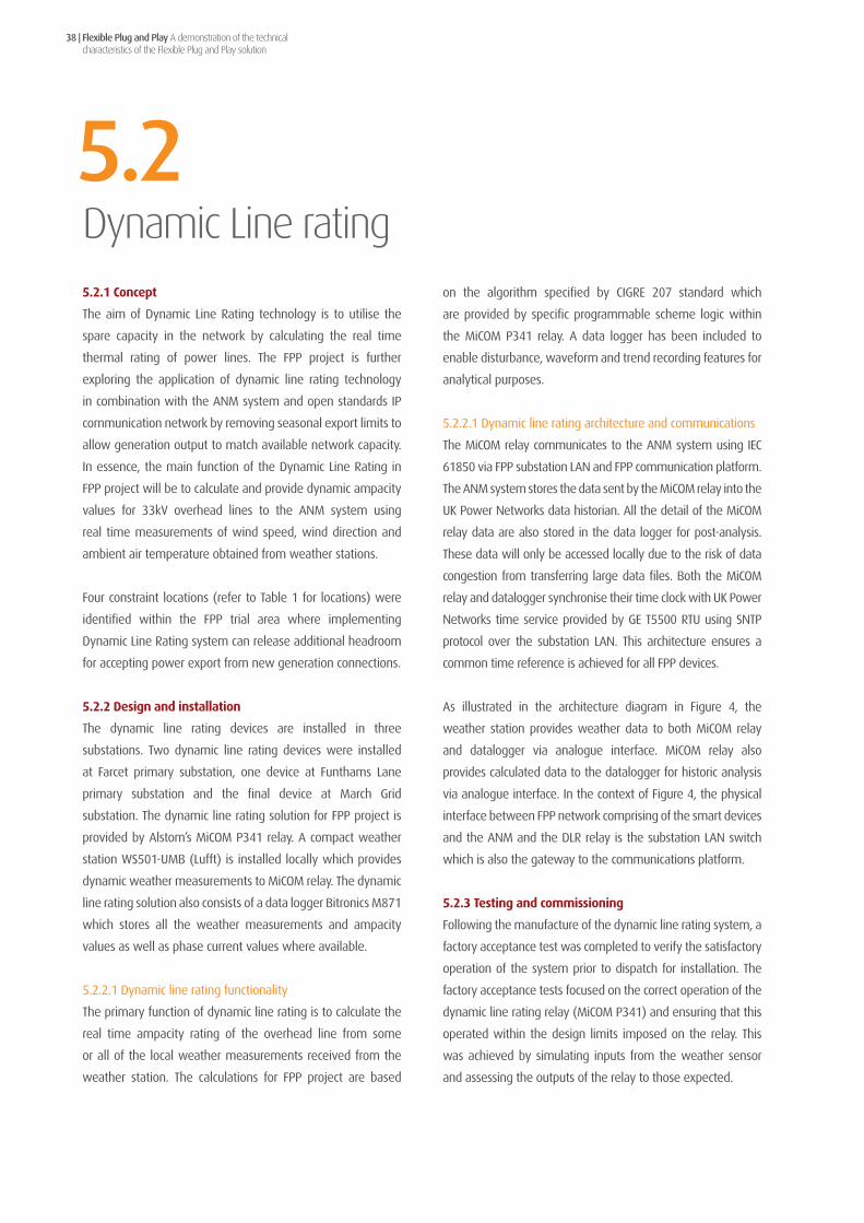
Flexible Plug and Play A demonstration of the technical characteristics of the Flexible Plug and Play solution
38 |
Dynamic Line rating5.25.2.1Concept
The aim of Dynamic Line Rating technology is to utilise the
spare capacity in the network by calculating the real time
thermal rating of power lines. The FPP project is further
exploring the application of dynamic line rating technology
in combination with the ANM system and open standards IP
communication network by removing seasonal export limits to
allow generation output to match available network capacity.
In essence, the main function of the Dynamic Line Rating in
FPP project will be to calculate and provide dynamic ampacity
values for 33kV overhead lines to the ANM system using
real time measurements of wind speed, wind direction and
ambient air temperature obtained from weather stations.
Four constraint locations (refer to Table 1 for locations) were
identified within the FPP trial area where implementing
Dynamic Line Rating system can release additional headroom
for accepting power export from new generation connections.
5.2.2Designandinstallation
The dynamic line rating devices are installed in three
substations. Two dynamic line rating devices were installed
at Farcet primary substation, one device at Funthams Lane
primary substation and the final device at March Grid
substation. The dynamic line rating solution for FPP project is
provided by Alstom’s MiCOM P341 relay. A compact weather
station WS501-UMB (Lufft) is installed locally which provides
dynamic weather measurements to MiCOM relay. The dynamic
line rating solution also consists of a data logger Bitronics M871
which stores all the weather measurements and ampacity
values as well as phase current values where available.
5.2.2.1 Dynamic line rating functionality
The primary function of dynamic line rating is to calculate the
real time ampacity rating of the overhead line from some
or all of the local weather measurements received from the
weather station. The calculations for FPP project are based
on the algorithm specified by CIGRE 207 standard which
are provided by specific programmable scheme logic within
the MiCOM P341 relay. A data logger has been included to
enable disturbance, waveform and trend recording features for
analytical purposes.
5.2.2.1 Dynamic line rating architecture and communications
The MiCOM relay communicates to the ANM system using IEC
61850 via FPP substation LAN and FPP communication platform.
The ANM system stores the data sent by the MiCOM relay into the
UK Power Networks data historian. All the detail of the MiCOM
relay data are also stored in the data logger for post-analysis.
These data will only be accessed locally due to the risk of data
congestion from transferring large data files. Both the MiCOM
relay and datalogger synchronise their time clock with UK Power
Networks time service provided by GE T5500 RTU using SNTP
protocol over the substation LAN. This architecture ensures a
common time reference is achieved for all FPP devices.
As illustrated in the architecture diagram in Figure 4, the
weather station provides weather data to both MiCOM relay
and datalogger via analogue interface. MiCOM relay also
provides calculated data to the datalogger for historic analysis
via analogue interface. In the context of Figure 4, the physical
interface between FPP network comprising of the smart devices
and the ANM and the DLR relay is the substation LAN switch
which is also the gateway to the communications platform.
5.2.3Testingandcommissioning
Following the manufacture of the dynamic line rating system, a
factory acceptance test was completed to verify the satisfactory
operation of the system prior to dispatch for installation. The
factory acceptance tests focused on the correct operation of the
dynamic line rating relay (MiCOM P341) and ensuring that this
operated within the design limits imposed on the relay. This
was achieved by simulating inputs from the weather sensor
and assessing the outputs of the relay to those expected.

Flexible Plug and Play A demonstration of the technical characteristics of the Flexible Plug and Play solution
| 39
Following the successful installation of the equipment, final
testing and commissioning was undertaken to verify the
correct operation of the Dynamic line rating Relay (P341)
and the data logger (M871). An overview of this testing and
commissioning is described as follows:
• Dynamic Line Rating relay: The settings within the
dynamic line rating relay (P341) were verified against
those developed during the design phase of the project.
Data generated by the weather station was then collected
through the relay and used to calculate the ampacity using
the CIGRE standard. This calculated ampacity value was
compared against the ampacity value generated within the
relay to check its validity.
• Data logger (M871): The information recorded within
the data logger has been checked to verify that it aligns
with the information generated by the weather station and
dynamic line rating relay.
When the dynamic line rating devices were commissioned
on sites, the final site integration was undertaken to ensure
that the equipment was able to send information to the ANM
system. The dynamic line rating devices were connected
to the LAN using fibre links and the local connectivity was
tested. At the first stage a 61850 Client simulator was used
to interact locally with the dynamic line rating devices. The
Client simulator was able to connect to the dynamic line rating
systems, acting as an IEC 61850 Server, to read information
from the relay and to subscribe to identified data such weather
information or ampacity. Then the relays were connected
to the RF mesh infrastructure to run end-to-end tests with
the ANM system. During the tests weather information and
ampacity were successfully sent to the centralised system.
The results of these tests have been captured into the site
integration test schedules to provide the evidences of the
successful integration of the dynamic line rating into the FPP
technical solution.
Figure 6: Dynamic line rating architecture diagram
Dynamic Line Rating System - Alstom
5
32
1
6
4
CTs P341
M871
Flexible Plug and Play Network
Weather station
Key
Current measurements
Weather station analogue output to data logger M871
Weather station analogue output to DLR P341
DLR P341 analogue output 4-20mA to data logger M871
Fibre link to FPP Network (IEC61850 and SNTP)
Ethernet link to FPP Network (SNTP)
1
2
3
4
5
6

Flexible Plug and Play A demonstration of the technical characteristics of the Flexible Plug and Play solution
40 |
Automatic Voltage Controller (AVC)5.35.3.1 Concept
The high penetration of DG around March Grid significantly
changes behaviour of the distribution network around that
area. High volumes of generation connecting onto the network
affects the voltage profile on the distribution network, and
possible unacceptable voltage rise at the point of common
coupling (PCC). Like other distribution networks, the original
design does not consider bi-directional power flows, voltage
rise contributions from DG, and other associated impacts. As
a result standard voltage regulation strategies are unable to
satisfactorily deal with these problems. Modern novel solutions
are required to allow bi-direction power flows with voltage
regulating strategies equipped to handle the effects of DG on
system voltage profile. The aim of AVC trials is to provide an
innovative automatic voltage control scheme integrated with
ANM and could help in addressing voltage issues caused by DG.
The SuperTAPP n+ relay from Fundamentals has recently been
approved by UK Power Networks for use on the distribution
network. The FPP trial aims to build on this success and
address, among other things, the following:
• The benefits associated with the interaction of SuperTAPP n+
with other smart technologies, such as the ANM.
• Identifying the voltage headroom provided through the use
of the SuperTAPP n+ within the FPP project area, specifically
at March Primary where a cluster of DG is connecting.
The trials will include:
• Prove communication of SuperTAPP n+ with ANM using IEC
61850 Standard.
• Assess the possible interaction between the local and
centralised voltage regulation strategy.
• Remote measurement of voltage using SuperTAPP n+
5.3.2 Design and installation
The FPP has installed a set of SuperTAPP n+ relays at both
March Grid and March Primary (refer to single line drawing in
Appendix 3) as described in Figure 7:
Figure 7: Simplified SuperTAPP n+ Connection
Key
On Load Tap Changer
OLTC
X X
VTARG
VG
VLDC
SuperTAPPn+ Relay
Feeder 1
Feeder 2
IFG
IL1
IG
IL2
VVT I
TL

Flexible Plug and Play A demonstration of the technical characteristics of the Flexible Plug and Play solution
| 41
The existing AVC schemes at March Grid and March Primary
are equipped with SuperTAPP and MVGC01 relays respectively.
These have been replaced with Supertapp N+ which will
provide more accurate voltage control at substation level and
will also interface with the ANM system via the IEC 61850
protocol.
March Grid 132/33kV substation comprises 2 x 45MVA grid
transformers fed at 132kV by two overhead line circuits from
Walpole Grid Supply Point and interconnected to Peterborough
Power Station. The 132kV circuits are teed to Walsoken Grid
and Peterborough Central Grid. The simplified single line
drawing is shown in Appendix 3.
5.3.3Testingandcommissioning
The AVC system was visually inspected and electrically tested
prior to energising, with functional tests undertaken to confirm
that the scheme is operating as required. The scheme was
then connected with UK Power Networks’ SCADA and tested
to confirm that alarms. Indications and controls operate as
designed.
Final site integration was undertaken to ensure that the
equipment was able to send information to the ANM system.
The AVC devices were connected to the LAN and the local
connectivity was tested. At first stage a 61850 Client simulator
was used to interact locally with the AVC devices. The client
simulator was connected to the AVCs, acting as an IEC 61850
Server, to read information from the relay and to subscribe
to identified data such voltage measurement or tap position.
Then the AVCs were connected to the RF mesh infrastructure to
run end-to-end tests with the ANM system. During these tests
the voltage information and tap position were successfully sent
to the centralised system. The results of these tests have been
captured into the site integration test schedules to provide the
evidences of the successful integration of the AVCs into the FPP
technical solution.

Flexible Plug and Play A demonstration of the technical characteristics of the Flexible Plug and Play solution
42 |
Remote Terminal Unit (RTU)5.45.4.1Concept
In existing distribution network architecture, Remote Terminal
Units (RTU) are installed into the substations (grid, primary and
also some distribution substations) in order to provide network
control and monitoring functionality by communicating with
the SCADA system. As part of business as usual UK Power
Networks install RTUs delivered by GE Power Conversion from
its product line T5500, which uses the a legacy communication
method that relies on satellite links.
As part of the FPP architecture, the primary function of the
RTU is to collect relevant substation data and communicate this
data to the ANM system. This function for FPP is additional
to the RTU’s normal functionality unrelated to FPP. The main
innovation introduced by the project is the use of the IEC 61850
standard to enable this communication outside the substation
via the RF mesh.
The IEC 61850 is a standard widely used to implement new
generation of electrical substation, which allows for a design
scalable architecture. This choice has also been driven by the
necessity to separate the flow of information transmitted to
the SCADA system which uses a DNP3 protocol. Indeed all
the RTUs also continue to communicate directly with ENMAC
via a separate communications port on the RTU and separate
communications infrastructure independent of the FPP Wide
Area Communications Infrastructure
5.4.2Designandinstallation
FPPrequirementsfortheRTUupgrade
One of the key requirements of for the RTU is the ability to
provide all data items to the ANM system, although the RTU is
configurable such that only data relevant to the ANM system
are provided. Also the RTU has the capability to receive data
items from the ANM system, although the RTU is configurable
such that only data relevant to the RTU are provided.
The RTU collects information from the new devices introduced
as part of the FPP project, for the purposes of providing
this information to ENMAC via the existing RTU to ENMAC
communication links.
The RTU utilises at a minimum, the following communications
protocols (over and above those protocols already in use
for communications between the RTU and other connected
systems/devices such as ENMAC):
• IEC 61850 is used for communications between the RTU
and ANM. The RTU is configured as an IEC 61850 server.
In order to optimise limited bandwidth available on the
Wide Area Communications Infrastructure, data volumes
and packet sizes are optimised in terms of minimising the
overhead introduced by the protocol itself. This is likely to
require the configuration of report control blocks in the RTU,
and buffered and/or unbuffered reporting from the servers
being triggered by exception.
• DNP3 over IP is used for communications between the RTU
and local devices. The RTU is configured as the DNP3 master.
• IEC 60870-5-103 is used for serial communications between
the novel protection relays and the RTU.
The RTU functions as a network time server, utilising SNTP as
defined in IEC 61850 to permit time synchronisation for all
smart devices connected on the substation LAN.
NewfunctionalitiesoftheupgradedRTU
To match with the required FPP specification, GE Power
Conversion implemented changes into its T5500 product.
More precisely the T5500 Processor firmware and the T5500
configuration tool have been upgraded to enable the RTU
to interface with an ANM system as required. The new
developments have implemented the following functionalities:

Flexible Plug and Play A demonstration of the technical characteristics of the Flexible Plug and Play solution
| 43
• IEC61850 Server: The interface to the ANM has been
designed to be by IEC 61850 protocol over a LAN. In this
design, the ANM acts as a 61850 Client and the RTUs
behave as IEC 61850 Servers. However, the existing RTUs
installed into the substations did not incorporate IEC 61850
Servers’ functionalities which have been developed by
GE Power Conversion for the FPP technical solution. For
the implementation, the IEC 61850 core ACSI services are
supported via MMS. The implementation does not require
supporting Sampled Values, Generic Object Oriented
Substation Events or Generic Substation Status Events.
The IEC 61850 server enables the ANM to subscribe to the
RTU and request data on change events from specified data
points. The server implementation uses predefined Report
Control Blocks (RCBs) for data transfer to client devices
(such as the ANM). In this respect, the server provides
the functionality required as configured using the RTU
Configuration Tool. Either one pair of RCBs per RTU or one pair
per Logical Device as required at the configuration time. In
this context, a pair will consist of a buffered RCB for reporting
digital inputs and an unbuffered RCB for analogue changes.
• IEC 61850 Server Configuration Tool: The T5500 reads
its configuration from an SCL file of type ICD and a data
mapping file, both generated by the T5500 Configuration
Tool. Any T5500 Digital or Analogue Input points which are
to be reported on the IEC 61850 interface are mapped to
Data Objects using a data mapping file. The configuration
process is detailed further in the report.
• SNTP TimeServer: The RTU acts as a time server, using
the GPS clock input available to it to maintain its clock,
and allowing other devices of the FPP technical solution to
synchronise with the time server in the RTU by sending it
SNTP requests. The SNTP server will respond to SNTP requests
from other devices on the network, or it can be configured
to broadcast or multicast the time at regular intervals. This
requirement ensures a common time reference is achieved
for all FPP devices.
The aim of these new developments is to provide necessary
measurements and indications from substation equipment to
ANM. This information enables ANM to determine the network
status and running arrangement for its calculations. As part of
the business as usual function, the RTU also interfaces with
some of the FPP smart devices such as QBCS, AVC and novel
protection relay to provide SCADA communications to ENMAC
as presented in the Figure 1. Also the RTU communicates
with Optical Current Transformer solution via DNP3 which
provides current measurement to ANM and other necessary
measurements to ENMAC.
RTUarchitectureandcommunications
The RTU communicates with ANM using IEC 61850 via FPP
substation LAN and FPP communications platform. However,
RTU is a critical component in the FPP architecture acting as
a common component shared between ENMAC and ANM. To
prevent any interference to SCADA network, the FPP network
will connect to RTU via a spare ethernet port which provides
both logical and physical separation between two networks.
• ENMAC communications: The RTU provides SCADA
communications to ENMAC via DNP3 protocol over SCADA
LAN and SCADA communications infrastructure. Ethernet
port 1 and a number of serial ports are used for SCADA
functionalities.
• FPPcommunications: The RTU communicates with ANM
via IEC 61850 standard using the spare ethernet port 2 over
FPP LAN and FPP communications platform. Ethernet port
2 will also be used for time synchronization service using
SNTP protocol and also to communicate with optical Current
Transformer solution via DNP3 protocol.

Flexible Plug and Play A demonstration of the technical characteristics of the Flexible Plug and Play solution
44 |
5.4.3Testingandcommissioning
In total 12 RTUs were upgraded into 2 Grid substations and 10
Primary substations. The replacement of the technical panels
was completed following the business as usual procedure.
After the RTUs were installed and commissioned on the
relevant substations into the trial area, final site integration
was undertaken to ensure that the equipment were able to
send information to the ANM system. For each site, the RTU
was connected to the LAN using fibre links and the local
connectivity was tested. At first stage a 61850 Client simulator
was used to interact locally with the RTU devices. The client
simulator was able to connect the RTUs, acting as an IEC 61850
Server, to read information from the RTU and to subscribe
to identified data such digitals or analogue. Then the RTUs
were connected to the RF mesh infrastructure to run end-to-
end tests with the ANM system. Digital and analogue signals
were successfully sent to the centralised system. The results
of these tests have been captured into the site integration
test schedules to provide the evidences of the successful
integration of the RTUs into the FPP technical solution.

Flexible Plug and Play A demonstration of the technical characteristics of the Flexible Plug and Play solution
| 45
Novel protection relays5.55.5.1Concept
To improve the network capacity with regards to connection
of DG, it is important to allow the power flow to be in both
directions across the 132/33kV Grid transformers. At March
Grid the generation connections have reached its limit due the
reverse power flow restriction caused by the Directional Over-
Current (DOC) relays. The installation of a novel protection
scheme will provide a workable alternative to overcome the
limitation of the existing DOC protection.
Operationally within the business UK Power Networks’
standard for backup to the intertrip scheme on 132kV system
is DOC. With increasing DG connections reverse power flow
capacities, constrained by use of the DOC schemes, are
exceeded. Non-standard novel protection methods, use of
intertripping or generator constraining at risk period may
alleviate this problem.
Instead of applying DOC, novel protection relays that allow
full capacity of the transformers to be utilised for reverse
power flows can be used. Whereas Directional Negative Phase
Sequence (DNPS) may offer possibilities, this protection has not
been proven in practice. The FPP project therefore provides the
opportunity to install the DNPS in combination with Directional
Voltage Dependent Over-current (DVDO) in a ‘monitor/alarm
only’ mode. Two of these schemes have been installed for trial
at March Grid and Peterborough Central, and will operate in
parallel with the DOC.
The DNPS protection is limited to 132kV sites. It could however,
once accepted, provide a useful additional protection option at
other primary UK Power Networks sites.
5.5.2Designandinstallation
The ‘main’ protection on the 132kV circuits from Walpole –
March – Peterborough Central is via pilot cables rented from
BT. At present UK Power Networks relies on DOC to back up the
intertripping function. The reverse power capacity is reached
well before the transformers reach their thermal or tap change
capabilities, which is limited by the maximum settings that
can be applied to the DOC protection. The DOC is normally
set at 50% of the transformer MVA rating. At both March and
Peterborough Central the DOC is currently set at 75%, which
the highest it can be set without losing its sensitivity and
becoming unable to detect faults.
The FPP project considered three alternative protection
philosophies available within Alstom’s P142 relay to replace
the DOC relays:
1.DirectionalVoltageDependantOvercurrent(DVDOC)on
the33kVside: This scheme only covers three phase faults
on the 132kV side. No issues identified.
2.Directional Negative Phase Sequence (DNPS) on the
33kVside: This scheme covers phase to phase and phase
to earth faults on the 132kV side. The studies show this
scheme is a potential solution, however its stability could
not be proven. The background “normal” and “abnormal”
levels of NPS for normal running and fault types that the
system must be stable for could not be determined. From
that point of view it is very difficult to determine whether
this scheme would remain stable without carrying out an
actual trial on the field and testing the scheme under real
network fault conditions.
3.NeutralVoltageDisplacement(NVD)onthe132kVside:
This scheme covers all types of the above faults, however it
will require set of CVTs on the 132kV side. Also this scheme
is non-directional, which means it needs to be slow enough
to discriminate against LV faults.
Based on the above it was recommended that a combination
of DVDOC and DNPS is used only for alarm but not for tripping.
These schemes initially will be monitored to assess their
performance against various faults and when a confidence

Flexible Plug and Play A demonstration of the technical characteristics of the Flexible Plug and Play solution
46 |
level is established then they could be adopted more widely
(or dropped as the case may be).
The relays are connected with the March Grid and Peterborough
Central RTUs to communicate with the UK Power Networks’
SCADA system via legacy communication links. Considering the
protection functionalities of these particular relays, there is no
need for data information exchanges with the ANM system.
5.5.3Testingandcommissioning
The protection relays (P142) that were used by the project
are UK Power Networks approved protection relays and,
as such, were commissioned using the same process as for
a typical protection relay. The difference is in the additional
functionality being trialled, including the directional negative
phase sequence and voltage dependant overcurrent protection
philosophies.
For completeness, below is a high level overview of the
commissioning process undertaken:
The protection settings and scheme logic are downloaded
onto the protection relay and are then verified to confirm they
match those approved during the design process. The relay is
then secondary injected to check the drop off and pick up of
all of the protection functions. These include a pick up at 200A
with a time delay of 250ms for the directional negative phase
sequence protection and a reduction in the overcurrent setting
to a quarter of the default setting (1200A down to 300A) in
the event that the voltage drops to below 24kV for the voltage
dependant overcurrent. This is followed by functional checks
which verify the operation of the trip relays and the alarms
generated. Once complete, the protection settings and scheme
logic are checked once again to confirm there have been no
changes throughout the commissioning process.

Flexible Plug and Play A demonstration of the technical characteristics of the Flexible Plug and Play solution
| 47
Ring Main Units for network reconfiguration5.65.6.1Concept
The original scope of the project included a provision for two
frequent use switches to be deployed at a strategic location
on the 33kV overhead line circuits between Peterborough
Central and March Grid substations to enable seasonal running
arrangements and network reconfiguration to maximise the
DG connected onto the network. Since then, it was identified
that a reinforcement project currently being carried out at the
same strategic location that will utilise Ring Main Units (RMUs)
that it can deliver the same functionality. As such there was no
need to install the frequent use switches and this change to
the project was formally approved by Ofgem.
5.6.2Designandinstallation
The RMUs are being installed to address an existing issue with
the loading of the 33kV circuits feeding Chatteris, Whittlesey
and Funthams Lane from March Grid.
The RMUs will provide the flexibility to run the network
with normally open points (NOPs) on the March Grid legs
at Whittlesey (see Appendix 4). This will enable Funthams
Lane and Whittlesey primary substations to be fed from
Peterborough Central and overcome the loading issue referred
to above. Through the ANM system, the project will monitor
the status of the March Grid legs of the Whittlesey RMUs, and
the setup will improve the network configuration changes by
increasing the flexibility to move load between Peterborough
Central and March Grid.
The control of the RMUs uses the legacy communication
network up to the UK Power Networks’ SCADA centre.
Distribution substations RTUs are installed to interface the
SCADA and the RMUs via DNP3 protocol. The ANM system
monitors the position of the switches so that its database
reflects the topology of the network (see section 7.1.3). The
switch position will be sent from the UK Power Networks’
SCADA to the ANM system using the existing DNP3 link
between the two environments. The feasibility of this solution
has been successfully tested during the acceptance tests of the
ANM production system. The solution will be configured when
the RMUs will be commissioned.
The 33kV Areva FBE RMUs are positioned on site, within
a self-contained GRP container. They are not electrically
connected, although are recorded on the asset management
tool as being available on site. Works on the cable circuits into
Peterborough Central are currently being carried out and to be
completed first (Q4 2013) before connecting the Whittlesey
RMUs (Q2 2014) to avoid the network being at risk, regarding
the removal of a 33kV link at Whittlesey Primary that cannot
be removed until the circuit work is complete.

6SmartApplications

Flexible Plug and Play A demonstration of the technical characteristics of the Flexible Plug and Play solution
| 49
As presented in the section 3, the network remaining capacity
into the FPP trial area is not sufficient to be able to offer firm
connections to new DG developers. Thus during the FPP trial,
the ANM will monitor and control the network so that the
existing remaining capacity can be fully exploited for new
interruptible connections.
ANM will involve the adoption of a platform and associated
autonomous software applications, from Smarter Grid
Solutions, to monitor and control the network in real time
to ensure it remains within its operating constraints. Within
the FPP project, several ANM applications will be deployed
including power flow management and voltage management
applications. The project also will also trial a thermal ratings
application which increases the capacity of the network when
weather cooling effects allow more power to be transferred,
particularly through overhead lines.

Flexible Plug and Play A demonstration of the technical characteristics of the Flexible Plug and Play solution
50 |
Design6.16.1.1ANMcomponents
The ANM system is composed of several centralised servers
communicating with the field devices as described in Figure 8.
CommunicationFrontEnd(sgscommshub)
The communication front end performs all data handling
and processing for the ANM system via a range of industry
protocols. The communication front end is configured to use IEC
61850, DNP 3.0 and OPC for the project. The Communication
front end is deployed on two Windows servers; one runs as
main and the other as a standby. The Communication front
end runs eXtremeDB, a real time database, and uses this to
communicate with the Application Server.
ApplicationServer(sgscore)
The application server is a modular, integrated, flexible and
scalable execution environment upon which the SGS smart
applications (i.e. Power Flow Management Application, Voltage
Management Application, Dynamic Ratings Application)
are deployed. The application server is deployed on two
Linux servers; one runs as main and the other as a standby.
The application server runs eXtremeDB and uses this to
communicate with the communication Front End.
PowerFlowManagementApplication(sgspowerflow)
The Power Flow Management Application manages the
power flow through chosen points on the network ensuring
it remains below specific thresholds. Power flow limits are
related to the thermal constraints of network equipment, such
as transformers or overhead lines. In order to perform power
flow management the current or power flow through the
chosen points on the network, also referred to as constraint
locations or ANM zone boundaries, are measured directly or
derived from the measurement of current or power flow at
other points on the network. Power flow management is
achieved by regulating the output of distributed generators
whose power export impacts on the power flow through
constraint locations on the distribution network.
VoltageManagementApplication(sgsvoltage)
The Voltage Management Application manages voltage at
chosen points on the network ensuring it remains within
specific thresholds. In order to perform voltage management
the voltage at the chosen points on the network, also referred
to as constraint locations, are measured directly or derived
from the measurement of voltage at other points on the
network. Voltage management is achieved by regulating
chosen parameters of controllable devices (i.e. in the case of
FPP, the real and reactive power of generators) associated with
the voltage constraints.
It is possible that the Power Flow Management Application
and the Voltage Management Application are controlling the
same device. In this case, there is an arbitration process which
decides on the priority action. For example, if both the Power
Flow Management Application and the Voltage Management
Application need to curtail a generator, the arbitration
compares the curtailment values and applies the lower of the
two values. At the time of writing, no such common devices
have been identified.
DynamicRatingsApplication(sgsratings)
The Dynamic Ratings Application monitors weather and
network information, and calculates the line power/ampacity
ratings for use by the Power Flow Management Application.
GeneratorController(sgsconnect)
The Generator Controller interfaces with and controls devices
connected to the network. It is deployed at each location of
a device controllable by the ANM system, receiving set-point
signals and transmitting these to the native control system of
devices under the control of the ANM. The generator controller

Flexible Plug and Play A demonstration of the technical characteristics of the Flexible Plug and Play solution
| 51
also implements an autonomous fail-safe mechanism in the
event of non-compliance, loss of communications or abnormal
operation. The generator controller includes a local Human
Machine Interface (HMI). Within this project, the Generator
Controller connects to generators and communicates that data
to the ANM via the IEC 61850 protocol.
Figure 8: General ANM architecture
sgs core (Main)
sgs power flow
sgs voltage
sgs ratings
sgs core (Standby)
sgs power flow
sgs voltage
sgs ratings
sgs comms hub (Main) sgs comms hub (Standby)
eXtremeDB
IP based WAN
IEC 61850 DNP 3.0 IEC 61850 DNP 3.0
IEC 61850 IEC 61850 IEC 61850 IEC 61850 IEC 61850
RTU (GE Power Conversion) sgs connect
Quad Booster
Current Transformer
DLR (incl Weather station)
Voltage Transformer
FUS AVC
DG
(vendor-specific com)
Weather station

Flexible Plug and Play A demonstration of the technical characteristics of the Flexible Plug and Play solution
52 |
Externalapplications
The ANM system passes data to two existing UK Power
Networks systems as shown in Figure 9:
1.TheSCADAsystem(ENMAC): ENMAC application provided
by GE Network solutions is the UK Power Networks
network management system. ANM exchanges data to
ENMAC application and presents itself as one of the RTU
objects to Control Engineers providing alarms, indications,
measurements and control functionality.
2.Thedatahistorian(PI):PI system provided by OSIsoft, is
the UK Power Networks central repository for operational
data and events including SCADA events. The ANM
communicates with PI using the Communication Front
End over the existing UK Power Networks communication
infrastructure. Any changes in the real-time database of
ANM are pushed to PI for storage.
The ANM system also receives control signals from ENMAC as
control engineers can enable/disable the ANM status of the
overall scheme, specific zones or specific generators.
Figure 9: Communication with external applications
sgs comms hub (Main) sgs comms hub (Standby)
IEC 61850 BACKHAUL
DNP 3.0 OPC DPN 3.0 OPC
DPN 3.0 OPC
ENMAC PI

Flexible Plug and Play A demonstration of the technical characteristics of the Flexible Plug and Play solution
| 53
6.1.2ANMRedundancyandFailsafeMode
Redundancy
The ANM hardware used for the trial is designed on “dual-
redundancy” principles; all hardware within the control centre
(i.e. the Communication Front Ends, Application Servers, and
the network switches) is duplicated such that the failure of
a single hardware item does not cause the ANM system to
fail. In addition to this dual-redundancy, each of the servers
is specified with its own internal redundancy: each server has
two power supplies, two network cards, multiple hard disks
configured as RAID 5 with a hot standby disk, two processors,
and multiple memory cards.
Communicationfailuresandfailsafemode
If communications fail between the ANM and one of the field
devices providing measurement point data (RTU, QBCS or
AVC), the ANM places the relevant measurement point out of
service. The associated generator controller is instructed to set
the corresponding DG into its fail safe state. The fail-safe state
is configured per generator and is either:
• A configured set point.
• A pre-configured schedule of set points.
Similarly if a communications failure is detected between the
ANM and the generator controller, the generator controller
moves to a failsafe state and will take one of the following
actions, depending upon the configuration of the generator
controller:
• Issues each connected generator with a pre-configured fail
safe set point or
• Issues set points to each connected generator as dictated by
a pre-configured fail safe schedule.
Meanwhile the Power Flow and Voltage Management
Applications exclude the generator from all power flow
calculations. No control actions are attempted by either Power
Flow Application or Voltage Management Application on this
generator controller.
The communication failed state is entered by the generator
controller when communication has failed for a configurable
amount of time. The fail safe is specific to each generator
controller.
If a communication failure occurs with the dynamic line rating
or the weather station, the rating application is designed to
cope with missing data and uses the best data available to
provide a rating. In the event of the loss of all live data it uses
seasonal ratings which are stored within the ANM database.
6.1.3Networkrunningarrangements
In order to configure the ANM applications to manage the
FPP network, the network running arrangements have to be
known. There is a standard running arrangement (the normal
running arrangement) and this has been used during the power
systems analysis carried out by Smarter Grid Solutions. The
ANM applications can manage multiple running arrangements
if these are pre-defined and the relevant analysis completed.
The ANM will monitor the network topology using the status
of ring main unit and circuit breaker via information passed
from the RTUs or ENMAC.
A change in position of the switches entails dynamic
reconfiguration of the relationships between the Measurement
point and the Distributed Generators for the Power Flow
Management Application and Voltage Management
Application. When the ANM system recognises a change
in network configuration, the Power Flow Management
Application and Voltage Management Application read in the
configuration data (i.e. Measurement Points and Generators)
for the specific network arrangement and immediately use
these to manage the network.

Flexible Plug and Play A demonstration of the technical characteristics of the Flexible Plug and Play solution
54 |
6.1.4Productionplatform
ProductionANMHardware
The production ANM hardware (Figure 10) consists of the
following items:
• 2 x Application Servers;
• 2 x Communication Front Ends;
• 4 x Generator Controllers with dedicated HMI’s;
• 1 x Weather Station (a MetPak™ Pro Weather Station plus a RTU).
The ANM servers are installed into the UK Power Networks’
control centre and are managed according business as usual
rule by operational teams.
Figure 10: ANM production platform for site acceptance test
UKPN Network
Standalone Weather station site
Weather station
BrodersenRTU32
NetworkMeasurements
UKPNRTU
DLR
AVC Relay
QBCS
Generator Control System
BrodersenRTU32
SGSconnect
ANM DG Site x
AB Panel View
LocalUI
sgs connect panel
MOBUS
sgs core 1
sgs core 2
sgs comms hub 2HP
sgs comms hub 1HP
HP
HP
UKPN Switch
UKPN Switch
UKPNServer/RTU
UKPNENMAC
UKPNServer
PI Historian
Central Rack
DPN3.0
OPC
HMI Data
IEC61850

Flexible Plug and Play A demonstration of the technical characteristics of the Flexible Plug and Play solution
| 55
Testing and commissioning6.2The FPP project required the testing of the two sets of ANM
platform: Pre-production and Production. For each of these sets
of ANM system there were two test stages: factory acceptance
test and site acceptance test.
Factory acceptance tests were performed to test all functional
and non-functional elements of each sub-system component.
The factory acceptance tests were carried out on both the
pre-production and production sets of hardware, with test
simulators being used during the tests.
The site acceptance test of the ANM pre-production hardware
were carried out within an FPP-wide pre-production
environment (the integration laboratory) set up by UK
Power Networks which includes the relevant test simulation
equipment. Site acceptance test of the ANM Production
hardware was carried out once all the production equipment
had been installed in the live environment.
In order to ensure that all the relevant tests have been carried
out, the Acceptance Test Specification (ATS) for the ANM
system was defined. This document described a suite of tests
used to ensure that all functionality declared in the Functional
Design Specification is adhered to. It details the individual tests
performed at each stage of acceptance testing.
6.2.1Testprocedure
For all the acceptance test procedure, three test stages were
performed:
1.Hardwaretests: these tests ensure that all target hardware
is fit for purpose without testing any application logic. These
tests are performed at factory acceptance test and site
acceptance test for pre-production and production.
2.Data Transfer tests: Data transfer tests validate
communication and data exchange between all sub-system
elements with application logic loaded. Tests performed at
factory acceptance test ensure that all Generator Controller
instances and the other IEDs can communicate with the
Communication Front End at the data transfer level. The
tests performed at the site acceptance test validated the
data transfer between the target hardware not available
during the factory acceptance test. The data transfer tests
validate the capability of the ANM system to interoperate
with the external components mainly using IEC 61850 but
also other protocols (DNP3 and OPC).
3.End-to-End tests: Upon successful completion of all data
transfer and hardware tests the ANM scheme can be tested
as a single unit. Testing the functionality of the scheme as
a whole involves exercising core logic and observing how
all sub-system components interact with one another, from
end-to-end. All end-to end tests are performed at factory
acceptance test; most are repeated at site acceptance test.
6.2.2Testsimulation
During the acceptance tests, one of the key challenges was the
ability to simulate the different component of the architecture.
For this purpose a test simulator was used for the factory
acceptance test/site acceptance test of both pre-production
and production. This is provided on Smarter Grid Solutions
hardware and provides simulation of power system quantities,
allowing ANM applications to be tested against an environment
similar to that expected in production. The simulation functions
provided by the test simulator are described below.
• Measurement Point Simulation: The test simulator
includes a measurement point simulation algorithm for
each measurement point. This simulates the current and
voltage measurement at each measurement point. The
effect of firm generation on current and voltage measured
at measurement points is simulated. Varying the firm
generation represents a combination of firm generation and
load and is a value which can be manipulated manually to
vary the current and voltage at the measurement point. The

Flexible Plug and Play A demonstration of the technical characteristics of the Flexible Plug and Play solution
56 |
simulation function may be enabled or disabled to allow
tests to be carried out as required.
• Generator Simulation: The test simulator simulates the
feedback of the generation control system and input it
to Generator Controller. This tool simulates the output of
multiple DGs and provides the following functionality:
• Circuit Breaker Controls and Indications: This provides an
indication of the circuit breaker position based a trip or
close signal from the ANM system.
• DG Output: This simulates the output of the generator
based upon the ANM target set-point. A ramp algorithm
was used to permit a gradual change of the export power
towards the set-point.
• Communications: This allows communication between
Generator Controller and Communication Front End to
be stopped or started. This is used whilst testing the
response of Power Flow Management Application,
Voltage Management Application and Dynamic Ratings
Application to a loss of communications to Generator
Controller and other field devices.
• ExternalSystemSimulation: The test simulator includes
a DNP3 Client that simulates data transfer to/from the
UK Power Networks’ SCADA system (ENMAC). The test
simulator includes an OPC Client that simulates data transfer
to the UK Power Networks Data Historian (PI).
• SmartDevicesorIEDsSimulation:The test simulator includes
a 61850 server test harness which allows the simulation of
data transfer to/from any of the IEDs. The IEDs are AVC relays,
the QBCS, dynamic line rating devices and UK Power Networks
RTUs. For each device, the simulation includes 61850 data sets
and associated Report Control blocks.
6.2.3Results
The acceptance test activities related to the ANM system started
in February 2013 by the factory acceptance test of the pre-
production platform. All the tests described in the acceptance test
specification document and compatible with the architecture of
the pre-production platform were passed successfully.
The site acceptance test of the pre-production platform was
then completed forming the core element of the integration
laboratory and providing the evidence to the successful
delivery of pre-production interoperability test for FPP’s smart
applications as required for SDRC 9.4.
The ANM production servers were then installed at the
UK Power Networks’ control centre. In order to proceed most of
the test remotely, dedicated and secure links have been put in
place between the Smarter Grid Solutions offices in Glasgow,
the UK Power Networks Control Centre and the UK Power
Networks London offices.
For the purpose of the final site acceptance tests, two
generator controllers were temporarily installed in the trial
area into two substations (March Grid and Chatteris Primary).
The site acceptance test of the Production platform was
completed in July 2013 which met the requirement for the
successful installation and commissioning of production smart
applications as part of the evidence for SDRC 9.4.

| 57 Flexible Plug and Play Quadrature-booster Report – SDRC 9.8 | 57
7Next steps

Flexible Plug and Play A demonstration of the technical characteristics of the Flexible Plug and Play solution
58 |
The FPP technical solution was successfully commissioned on
the distribution network in September 2013 in readiness for
the transition of the prospective FPP trial phase running to the
end of 2014.
The telecoms platform was successfully delivered in March
2013 and further work has subsequently been undertaken to
understand the performance and limits of this technology with
integration of various components of the overall solution. The
on-going work on optimised use of IEC 61850 data over the
Radio Frequency Mesh communication infrastructure under
various system conditions, is a key area for innovation and
development.
The delivery of Quadrature Booster transformer in July 2013
generated significant learning for the business in both design
and commissioning areas. Further knowledge will be captured
during the trial phase when it will be closely monitored during
its operation in the live network.
Significant knowledge was generated as part of the design,
commissioning and testing process of all the smart devices
and the smart application. Key learning has been produced in
the areas of implementing an interoperable solution based on
IEC 61850. The learning generated will support and improve
any further roll-out and evolution the FPP technical solution.
In order to address the gap in skills and knowledge in the IEC
61850 standard within UK Power Networks, the FPP project has
started engaging and training relevant internal stakeholders
and will continue during the FPP trial phase.
One of the challenges of the project turned out to be resolution
of protection issues relating to the implementation of various
FPP solutions. This has enormously engaged both FPP team
and the business throughout the process stretching the
boundaries of our technical expertise.
Despite the utilisation of some proven technologies, FPP
project has attempted to gain further knowledge on their
capabilities by changing the approach on their operation and
integration with other solutions. ANM, Dynamic line rating and
Automatic Voltage Control will be those solutions generating
learning of that nature.
Trial plans are currently being developed in order to test the
main functionalities of the solution under various operational
scenarios and conditions. These trials will take place during 2014
in parallel with SDRC 9.6 (Implementation of active voltage
management with the trial area) and SDRC 9.7 (Implementation
of active power flow management within trial area).
The learning will be disseminated through a learning report, a
dissemination event, academic papers and bilateral engagement
with DNOs and interested parties and it will be shared via the
project website (www.flexibleplugandplay.co.uk).

8Appendices
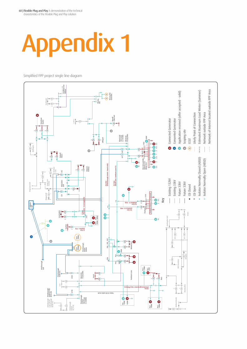
Flexible Plug and Play A demonstration of the technical characteristics of the Flexible Plug and Play solution
60 |
Appendix 1O
rton
P28
21
3 4
1
1
3
1
Pete
rbor
ough
Cent
ral
132/
33 k
V2
x 60
MVA
1 2 3
1
12 1
1 2
1
Sou
ther
y
1
1 2
2 1
12
P49
26.6
km
(Pet
erbo
roug
h Ce
ntra
l - M
arch
Grid
)
EM
L W
(S
)
5MW
G
Mar
ch P
rimar
y 11
kV N
etw
ork
9MW
Wis
sing
BSC
G
ener
ator
2.5
2.5
21
2
Max
dem
and
MW
Sum
mer
14.
5W
inte
r 20.
5
0.5
2.5
0.5
216
Wis
sing
BS
C
Swaf
fham
Tee
Wat
ton
Nor
thw
old
Dow
nham
Mar
ket
Wal
tingt
on
Out
wel
lM
oors
King
s Ly
nn G
rid
Wig
genh
all
King
s Ly
nnPr
w S
tn
Stric
tfas
tLa
ne
GT2
Wal
soak
enG
ridG
T1
Wis
bech
Railw
ay
No.
216
MW
No.
116
MW
P19
9.5
km(W
also
ken
- Lev
erin
gton
T2)
Leve
ringt
on
Guy
hirn
6.5 km(Guyhirn - P19)
1
23
Wal
pole
GSP
Pete
rbor
ough
East
Pete
rbor
ough
Sout
h G
T1 te
eBR
Ne
NE
Pete
rbor
ough
P w
r S tb
tee
Pete
rbor
ough
Nor
th G
T2
Pete
rbor
ough
Cent
ral
33/1
1 kV
EML
W (S
)73
(61)
MVA
Farc
et
12
Future 33 kV cable circuit
Ext.
12M
W
16M
W
No.
110
MW
No.
214
MW
Bury
1 2
No.
27.
2MW
No.
12M
W
20 km(Peterborough Central - Bury PRimary)
Upw
ell
Lake
s En
d1
Litt
lepo
rt12
Mar
ch G
rid13
2/33
kV
2 x
45 M
VA
EML
W (S
)59
(43)
MVA
GT1
GT2
12
1020
Mar
ch11
kV
10.2 km(Chatteris T2 - P49)
10.8 km(Chatteris T1 - P28)
18.3
km
(Mar
ch G
rid -
Funt
ham
s La
ne T
1)
12
Chat
teris
11 k
V
Chat
teris
Prim
ary
11 k
V N
etw
ork
1
God
man
ches
ter
Woo
dwal
ton
Brin
gton
RA
F A
lcon
bury
GT2
GT1
Hun
tingd
on G
rid
St Iv
es
Pete
rbor
ough
Pow
erSt
atio
n
CCG
T35
0MW
CCG
T55
MW
P66
P80
P85
P87
P24
P10
NO
P
21
21
Whi
ttle
sey
Funt
ham
s La
ne
Pete
rbor
ough
Sout
h G
T2
GT1
BG
T2B
Key
Exis
ting
132k
V
Exis
ting
33kV
Futu
re 3
3kV
Futu
re 3
3kV
CB C
lose
d
CB O
pen
Isol
ator
Nor
mal
ly C
lose
d (A
BSD
)
Isol
ator
Nor
mal
ly O
pen
(ABS
D)
Conn
ecte
d Ge
nera
tor
Cons
ente
d Ge
nera
tor
Appl
icat
ion
rece
ived
(of
fer a
ccep
ted
- so
lid)
Scop
ing
site
CCGT
Like
ly P
oint
of C
onne
ctio
n
Estim
ated
Max
imum
Loa
d W
inte
r (Su
mm
er)
Net
wor
k ou
tsid
e FP
P Ar
ea
Net
wor
k of
Inte
rest
loca
ted
outs
ide
FPP
Area
Ort
on
P28
21
3 4
1
1
3
1
Pete
rbor
ough
Cent
ral
132/
33 k
V2
x 60
MVA
1 2 3
1
12 1
1 2
1
Sou
ther
y
1
1 2
2 1
12
P49
26.6
km
(Pet
erbo
roug
h Ce
ntra
l - M
arch
Grid
)
EM
L W
(S
)
5MW
G
Mar
ch P
rimar
y 11
kV N
etw
ork
9MW
Wis
sing
BSC
G
ener
ator
2.5
2.5
21
2
Max
dem
and
MW
Sum
mer
14.
5W
inte
r 20.
5
0.5
2.5
0.5
216
Wis
sing
BS
C
Swaf
fham
Tee
Wat
ton
Nor
thw
old
Dow
nham
Mar
ket
Wal
tingt
on
Out
wel
lM
oors
King
s Ly
nn G
rid
Wig
genh
all
King
s Ly
nnPr
w S
tn
Stric
tfas
tLa
ne
GT2
Wal
soak
enG
ridG
T1
Wis
bech
Railw
ay
No.
216
MW
No.
116
MW
P19
9.5
km(W
also
ken
- Lev
erin
gton
T2)
Leve
ringt
on
Guy
hirn
6.5 km(Guyhirn - P19)
1
23
Wal
pole
GSP
Pete
rbor
ough
East
Pete
rbor
ough
Sout
h G
T1 te
eBR
Ne
NE
Pete
rbor
ough
P w
r S tb
tee
Pete
rbor
ough
Nor
th G
T2
Pete
rbor
ough
Cent
ral
33/1
1 kV
EML
W (S
)73
(61)
MVA
Farc
et
12
Future 33 kV cable circuit
Ext.
12M
W
16M
W
No.
110
MW
No.
214
MW
Bury
1 2
No.
27.
2MW
No.
12M
W
20 km(Peterborough Central - Bury PRimary)
Upw
ell
Lake
s En
d1
Litt
lepo
rt12
Mar
ch G
rid13
2/33
kV
2 x
45 M
VA
EML
W (S
)59
(43)
MVA
GT1
GT2
12
1020
Mar
ch11
kV
10.2 km(Chatteris T2 - P49)
10.8 km(Chatteris T1 - P28)
18.3
km
(Mar
ch G
rid -
Funt
ham
s La
ne T
1)
12
Chat
teris
11 k
V
Chat
teris
Prim
ary
11 k
V N
etw
ork
1
God
man
ches
ter
Woo
dwal
ton
Brin
gton
RA
F A
lcon
bury
GT2
GT1
Hun
tingd
on G
rid
St Iv
es
Pete
rbor
ough
Pow
erSt
atio
n
CCG
T35
0MW
CCG
T55
MW
P66
P80
P85
P87
P24
P10
NO
P
21
21
Whi
ttle
sey
Funt
ham
s La
ne
Pete
rbor
ough
Sout
h G
T2
GT1
BG
T2B
Ort
on
P28
21
3 4
1
1
3
1
Pete
rbor
ough
Cent
ral
132/
33 k
V2
x 60
MVA
1 2 3
1
12 1
1 2
1
Sou
ther
y
1
1 2
2 1
12
P49
26.6
km
(Pet
erbo
roug
h Ce
ntra
l - M
arch
Grid
)
EM
L W
(S
)
5MW
G
Mar
ch P
rimar
y 11
kV N
etw
ork
9MW
Wis
sing
BSC
G
ener
ator
2.5
2.5
21
2
Max
dem
and
MW
Sum
mer
14.
5W
inte
r 20.
5
0.5
2.5
0.5
216
Wis
sing
BS
C
Swaf
fham
Tee
Wat
ton
Nor
thw
old
Dow
nham
Mar
ket
Wal
tingt
on
Out
wel
lM
oors
King
s Ly
nn G
rid
Wig
genh
all
King
s Ly
nnPr
w S
tn
Stric
tfas
tLa
ne
GT2
Wal
soak
enG
ridG
T1
Wis
bech
Railw
ay
No.
216
MW
No.
116
MW
P19
9.5
km(W
also
ken
- Lev
erin
gton
T2)
Leve
ringt
on
Guy
hirn
6.5 km(Guyhirn - P19)
1
23
Wal
pole
GSP
Pete
rbor
ough
East
Pete
rbor
ough
Sout
h G
T1 te
eBR
Ne
NE
Pete
rbor
ough
P w
r S tb
tee
Pete
rbor
ough
Nor
th G
T2
Pete
rbor
ough
Cent
ral
33/1
1 kV
EML
W (S
)73
(61)
MVA
Farc
et
12
Future 33 kV cable circuit
Ext.
12M
W
16M
W
No.
110
MW
No.
214
MW
Bury
1 2
No.
27.
2MW
No.
12M
W
20 km(Peterborough Central - Bury PRimary)
Upw
ell
Lake
s En
d1
Litt
lepo
rt12
Mar
ch G
rid13
2/33
kV
2 x
45 M
VA
EML
W (S
)59
(43)
MVA
GT1
GT2
12
1020
Mar
ch11
kV10.2 km(Chatteris T2 - P49)
10.8 km(Chatteris T1 - P28)
18.3
km
(Mar
ch G
rid -
Funt
ham
s La
ne T
1)
12
Chat
teris
11 k
V
Chat
teris
Prim
ary
11 k
V N
etw
ork
1
God
man
ches
ter
Woo
dwal
ton
Brin
gton
RA
F A
lcon
bury
GT2
GT1
Hun
tingd
on G
rid
St Iv
es
Pete
rbor
ough
Pow
erSt
atio
n
CCG
T35
0MW
CCG
T55
MW
P66
P80
P85
P87
P24
P10
NO
P
21
21
Whi
ttle
sey
Funt
ham
s La
ne
Pete
rbor
ough
Sout
h G
T2
GT1
BG
T2B
Ort
on
P28
21
3 4
1
1
3
1
Pete
rbor
ough
Cent
ral
132/
33 k
V2
x 60
MVA
1 2 3
1
12 1
1 2
1
Sou
ther
y
1
1 2
2 1
12
P49
26.6
km
(Pet
erbo
roug
h Ce
ntra
l - M
arch
Grid
)
EM
L W
(S
)
5MW
G
Mar
ch P
rimar
y 11
kV N
etw
ork
9MW
Wis
sing
BSC
G
ener
ator
2.5
2.5
21
2
Max
dem
and
MW
Sum
mer
14.
5W
inte
r 20.
5
0.5
2.5
0.5
216
Wis
sing
BS
C
Swaf
fham
Tee
Wat
ton
Nor
thw
old
Dow
nham
Mar
ket
Wal
tingt
on
Out
wel
lM
oors
King
s Ly
nn G
rid
Wig
genh
all
King
s Ly
nnPr
w S
tn
Stric
tfas
tLa
ne
GT2
Wal
soak
enG
ridG
T1
Wis
bech
Railw
ay
No.
216
MW
No.
116
MW
P19
9.5
km(W
also
ken
- Lev
erin
gton
T2)
Leve
ringt
on
Guy
hirn
6.5 km(Guyhirn - P19)
1
23
Wal
pole
GSP
Pete
rbor
ough
East
Pete
rbor
ough
Sout
h G
T1 te
eBR
Ne
NE
Pete
rbor
ough
P w
r S tb
tee
Pete
rbor
ough
Nor
th G
T2
Pete
rbor
ough
Cent
ral
33/1
1 kV
EML
W (S
)73
(61)
MVA
Farc
et
12
Future 33 kV cable circuit
Ext.
12M
W
16M
W
No.
110
MW
No.
214
MW
Bury
1 2
No.
27.
2MW
No.
12M
W
20 km(Peterborough Central - Bury PRimary)
Upw
ell
Lake
s En
d1
Litt
lepo
rt12
Mar
ch G
rid13
2/33
kV
2 x
45 M
VA
EML
W (S
)59
(43)
MVA
GT1
GT2
12
1020
Mar
ch11
kV
10.2 km(Chatteris T2 - P49)
10.8 km(Chatteris T1 - P28)
18.3
km
(Mar
ch G
rid -
Funt
ham
s La
ne T
1)
12
Chat
teris
11 k
V
Chat
teris
Prim
ary
11 k
V N
etw
ork
1
God
man
ches
ter
Woo
dwal
ton
Brin
gton
RA
F A
lcon
bury
GT2
GT1
Hun
tingd
on G
rid
St Iv
es
Pete
rbor
ough
Pow
erSt
atio
n
CCG
T35
0MW
CCG
T55
MW
P66
P80
P85
P87
P24
P10
NO
P
21
21
Whi
ttle
sey
Funt
ham
s La
ne
Pete
rbor
ough
Sout
h G
T2
GT1
BG
T2B
Ort
on
P28
21
3 4
1
1
3
1
Pete
rbor
ough
Cent
ral
132/
33 k
V2
x 60
MVA
1 2 3
1
12 1
1 2
1
Sou
ther
y
1
1 2
2 1
12
P49
26.6
km
(Pet
erbo
roug
h Ce
ntra
l - M
arch
Grid
)
EM
L W
(S
)
5MW
G
Mar
ch P
rimar
y 11
kV N
etw
ork
9MW
Wis
sing
BSC
G
ener
ator
2.5
2.5
21
2
Max
dem
and
MW
Sum
mer
14.
5W
inte
r 20.
5
0.5
2.5
0.5
216
Wis
sing
BS
C
Swaf
fham
Tee
Wat
ton
Nor
thw
old
Dow
nham
Mar
ket
Wal
tingt
on
Out
wel
lM
oors
King
s Ly
nn G
rid
Wig
genh
all
King
s Ly
nnPr
w S
tn
Stric
tfas
tLa
ne
GT2
Wal
soak
enG
ridG
T1
Wis
bech
Railw
ay
No.
216
MW
No.
116
MW
P19
9.5
km(W
also
ken
- Lev
erin
gton
T2)
Leve
ringt
on
Guy
hirn
6.5 km(Guyhirn - P19)
1
23
Wal
pole
GSP
Pete
rbor
ough
East
Pete
rbor
ough
Sout
h G
T1 te
eBR
Ne
NE
Pete
rbor
ough
P w
r S tb
tee
Pete
rbor
ough
Nor
th G
T2
Pete
rbor
ough
Cent
ral
33/1
1 kV
EML
W (S
)73
(61)
MVA
Farc
et
12
Future 33 kV cable circuit
Ext.
12M
W
16M
W
No.
110
MW
No.
214
MW
Bury
1 2
No.
27.
2MW
No.
12M
W
20 km(Peterborough Central - Bury PRimary)
Upw
ell
Lake
s En
d1
Litt
lepo
rt12
Mar
ch G
rid13
2/33
kV
2 x
45 M
VA
EML
W (S
)59
(43)
MVA
GT1
GT2
12
1020
Mar
ch11
kV
10.2 km(Chatteris T2 - P49)
10.8 km(Chatteris T1 - P28)
18.3
km
(Mar
ch G
rid -
Funt
ham
s La
ne T
1)
12
Chat
teris
11 k
V
Chat
teris
Prim
ary
11 k
V N
etw
ork
1
God
man
ches
ter
Woo
dwal
ton
Brin
gton
RA
F A
lcon
bury
GT2
GT1
Hun
tingd
on G
rid
St Iv
es
Pete
rbor
ough
Pow
erSt
atio
n
CCG
T35
0MW
CCG
T55
MW
P66
P80
P85
P87
P24
P10
NO
P
21
21
Whi
ttle
sey
Funt
ham
s La
ne
Pete
rbor
ough
Sout
h G
T2
GT1
BG
T2B
Simplified FPP project single line diagram

Flexible Plug and Play A demonstration of the technical characteristics of the Flexible Plug and Play solution
| 61
Appendix 2
Kings Lynn Grid Tee Waltington
Outwell Moors
Downham Market
Northwold
Swaffham
Watton LINE 1
LIN
E 2
Southery
Littleport
Wissington British Sugar 33kV Switching Station
TAPCON 260 monitored
QB 5-panel Switchboard (QB Switching Station)
A B D
C
3 2 1
1
2
3
8.275km 8.154km
11.07km
5.36
km
6.31km
NC
E
Wissington British Sugar CHP
Key
Existing 33kV
Future 33kV
Existing 11kV
Quad-Booster related network re-configuration
Circuit Breaker closed
Circuit Breaker open
A
B
C
D
E
NC Disconnector (normally closed)
Quad-Booster
On Load Tap Changer
Generator
Downham/Northwold Circuit Breaker
Quad-Booster Downham/ Northwold Side Circuit Breaker
Quad-Booster By-Pass Circuit Breaker (normally open)
Quad-Booster Wissington British Sugar Side Circuit Breaker
Quad-Booster Circuit Breaker at Wissington British Sugar Switching Station
Simplified Wissington 33kV single line diagram

Flexible Plug and Play A demonstration of the technical characteristics of the Flexible Plug and Play solution
62 |
Appendix 3
33kV
March Grid
To Lakes EndLittleport/ WissingtonTo March West
132kV
2MW 2.5MW 1MW 2MW 0.5MW 2.5MW
5MW11kV
March
1 2
March Primary 11kV Network
Max Demand MWSummer 14.5Winter 20.5
10MW 20MW
10MW
10MW
12
To Whittlesey, Funtham’s Lane
Max Demand MWSummer 11.3Winter 17.4
Chatteris Primary 11kV Network
2MW 0.5MW
11kVChatteris
4.75MW 6MW
GT245MVA
GT145MVA
Existing 132kV
Existing 33kV
Planned 33kV
Existing 11kV
Planned 11kV
Connected Generator
Planned Generator
11kV Load
Reverse Power Flows
33kV Circuit Breaker Closed
11kV Circuit Breaker Closed
Normally Open Point (planned)
132/33kV Transformer
33/11kV Transformer
Key
2.5MW
Reverse Power FlowLimit = 34 MVA per Grid Transformer
Single line diagram for AVC installation

Flexible Plug and Play A demonstration of the technical characteristics of the Flexible Plug and Play solution
| 63
Appendix 4
Peterborough Central
Farcet
Glassmoor Windfarm
Red Tile 1 Windfarm
Bury Primary(Huntingdon Grid)
504A 504A
671A
671A
March
Funtham’s Lane
Chatteris
Whittlesey
476A 476A
575A
651A
575A
351A
575A
575A
476A 476A
11kV
33kV underground
33kV overhead
33kV underground (new)
Normal open point
Key
Stage 2 - Split ‘Fleet Drove’ tee point and connect Funtham’s Lane circuits direct to Peterborough Central
Single line diagram for RMUs installation at Whittlesey

Flexible Plug and Play A demonstration of the technical characteristics of the Flexible Plug and Play solution
64 |
Appendix 5Table of evidence
3 P.0142.Flexible Plug and Play Integration Tests specification
4.2.2.3 P.0338.Active Network Management Client Certification
4.2.2.3 P.0339.sgs Connect Certification
4.2.2.3 P.0340.GE Remote Terminal Unit T5500 Certification
4.2.2.3 P.0341.Kalkitech SYNC2000 Certification (Communication interface for the SuperTAPP n+)
4.2.2.3 P.0342.MR TAPCOM260 Certification (QBCS)
4.2.2.3 P.0343.Alstom P341 Certification (dynamic line rating)
4.5.3 P.0334.Dynamic Line Rating 1a Farcet Commissioning Report
4.5.3 P.0335.Dynamic Line Rating 1b Farcet Commissioning Report
4.5.3 P.0336.Dynamic Line Rating 2 Funthams Lane Commissioning Report
4.5.3 P.0337.Dynamic Line Rating 4 March Grid Commissioning Report
4.6.3 P.0318.Active Voltage Control March Grid Commissioning Report
4.6.3 P.0319. Active Voltage Control March Primary Commissioning Report
4.7.2.3 P.0320.Remote Terminal Unit Wissington Commissioning Report
4.7.2.3 P.0321.Remote Terminal Unit March Primary Commissioning Report
4.7.2.3 P.0322.Remote Terminal Unit March Grid Commissioning Report
4.7.2.3 P.0323.Remote Terminal Unit Bury Commissioning Report
4.7.2.3 P.0324.Remote Terminal Unit Peterborough Central Commissioning Report
4.7.2.3 P.0325.Remote Terminal Unit Whittlesey Commissioning Report
4.7.2.3 P.0326.Remote Terminal Unit Chatteris Commissioning Report
4.7.2.3 P.0327.Remote Terminal Unit Littleport Commissioning Report
4.7.2.3 P.0328.Remote Terminal Unit Northwold Commissioning Report
4.7.2.3 P.0329.Remote Terminal Unit Southery Commissioning Report
4.7.2.3 P.0330.Remote Terminal Unit Farcet Commissioning Report
4.7.2.3 P.0331.Remote Terminal Unit Funthams Lane Commissioning Report
4.8.3 P.0332.Novel Protection Relay March Grid Commissioning Report
4.8.3 P.0333.Novel Protection Relay Peterborough Central Commissioning Report
5.2.3 P.0130.Active Network Management Acceptance Test Specification and Results
ReportSection Evidence

Flexible Plug and Play A demonstration of the technical characteristics of the Flexible Plug and Play solution
| 65
Appendix 6Additional project documentation available to GB DNOs
P.0098.Performance Spec for Enhanced AVC Scheme.
P.0130.Active Network Management Acceptance Test Specification and Results
P.0142.Flexible Plug and Play Integration Tests Specification
P.0154.Flexible Plug and Play Functional and Non-Functional Requirements Specification V1.0
P.0202.High Level Test Approach v1.0
P.0262.Dymanic Line Rating Functional Design Specification
P.0263.Novel Protection Relay Design Specification
P.0264.Quadrature-booster Control System, Production Specification
ReportName

UK Power Networks Holdings LimitedRegistered office: Newington House 237 Southwark Bridge Road London SE1 6NPRegistered in England and WalesRegistered number: 7290590