Embed Size (px)
Citation preview
Page 317
Flexible Pavement Design and Material Characteristics
Avvaru Tharun
M.Tech Student
Department of Civil Engineering,
Nalanda Institute of Engineering and Technology,
Kantepudi, Sattenapalli.
M Srinivas Reddy, M.Tech
Assistant Professor
Department of Civil Engineering,
Nalanda Institute of Engineering and Technology,
Kantepudi, Sattenapalli.
ABSTRACT
A typical flexible pavement consists of a subgrade,
sub-base, base course and two layers of asphalt
concrete mixes. The flexible pavements in India are
designed as per the specifications of the Indian
Roads Congress (IRC). In IRC: 37-2012, the
pavement is modelled as a multi-layer elastic
structure. The stresses and strains are evaluated
using linearized elastic theory. The thickness of the
pavement layers are selected duly considering the
allowable stresses and strains in the pavement layers,
including the subgrade.
The main concern related to pavement design is
material characterization. For constructing road with
superior quality, the highway material should meet
the quality requirements and is helpful in providing
good strength and longer life of pavements. The
highway consists of soil in subgrade, granular
material in sub-base/base, and bituminous mixture in
binder/surface layer. In the current study, the tests
that are carried out for characterizing the soil,
granular and bitumen explained clearly. In addition,
the allowable limits for selecting such materials are
also mentioned.
In India, according to IRC: 37 (2012), pavements are
designed to limit rutting and bottom-up fatigue
cracking. It provides design templates for six
different cross-sections, traffic levels and different
subgrade California Bearing Ratio (CBR) values.
These templates are designed for an Annual Average
Pavement Temperature (AAPT) of 35°C. Traffic is
considered in terms of Equivalent Standard Axle
Load (ESAL) and here the standard axle is defined
as a single axle dual wheel with a load of 80 kN.
IRC: 37 (2012) provides two distress prediction
models for rutting based on 80 and 90 percent
reliabilities. Resilient modulus (MR) is used as the
material property in the design of a pavement for
rutting according to IRC: 37 (2012). The IRC
method of pavement design provides a constant
granular layer thickness for different traffic levels.
The flexibility in changing the design is normally
available for the bituminous layers. Using resilient
modulus values and subgrade CBR, one should
assume thicknesses for bituminous layers and
determine stress-strain.
INTRODUCTION
INDIAN ROAD NETWORKS
The total length of Indian roads is about 4.32 million
kilometers. India is the second largest country in the
world after USA. The details of road networks are
shown below.
Road Classifications:
According to Lucknow plan, the roads are classified
as,
1. Based on primary basis and,
2. Urban roads
Based on Primary Basis:
Primary systems
i. Express ways
ii. National highways
Secondary systems
i. State highways
ii. Major district roads
Page 318
Tertiary systems
i. Other district roads
ii. Village roads
Urban roads:
i. Arterial roads
ii. Sub arterial roads
iii. Collector roads
iv. Local roads
According to Nagpur road plan, the roads are
classified as,
1. National highways
2. State highways
3. Major district roads
4. Other district roads
5. Village roads
National Highways:
National highways connects the capital region with
important cities of various states, business places,
important border places, provides best transportation
facilities.
The central government has taken up the development
of national highways by making the highways to 4/6
lanes along highly trafficked corridors and upgrading
of selected high density corridors. The development of
national highways was undertaken by the national
highways authority of India.
State Highways:
State highways connects the important places in the
state, national highways, business places in state etc.
state government will look after the construction &
maintenance of state highways. The design
specifications are same as national highways.
Major District Roads:
These roads provide the main road connectivity within
the districts, connect the state highways, provide
important transport facilities, business places etc.
These roads are also under the state government.
These roads have lower design specifications
compared to state highways.
Other District Roads:
These roads provide important connectivity within
mandals & Talukas, it connects the major district
roads in district, agricultural and market places etc. the
state government is responsible for the construction &
maintenance of these roads. These roads have lower
design specification when compared to Major District
roads.
Village Roads:
Village roads connect the other district roads with the
villages in rural areas, local market areas, and
agricultural places. The state government is
responsible for construction &maintenance of these
roads.
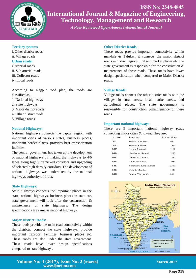
Important national highways
There are 9 important national highway roads
connecting major cities & towns. They are,
Page 319
Table 1.Details of Indian road networks
Andhra Pradesh Road Networks Statistics
The Roads &Building Department of Andhra Pradesh
is maintaining 69000 kms of roads which includes
National highways, State Highways, Major District
roads &rural roads. The lengths of roads in AP are
shown below
Table 2 AP road network details
Pavement composition
Sub base course
Sub base course comprises of the materials like natural
sand, moorum, gravel, laterite, kankar, brick, crushed
stone, crushed slag, and crushed concrete, thereof
meeting the prescribed grading and physical grading &
physical requirements.
When sub base course consist of various materials
then mixing shall be done mechanically, by using a
suitable mixer or adopting mix in place method.
Granular sub base course materials confirming to
clause 401 of MORTH specifications for road &
bridge works are recommended for use.
To say in simple words the sub base materials should
have a minimum CBR of20% to 30% for traffic up to
2 msa & traffic exceeding 2 msa respectively. Usually
the sub base consist granular or WBM and the
thickness should not be less 150mm for less than
150mm for design traffic less than10 msa and 200mm
for design traffic of 10 msa and above.
Base Course
The unbound granular bases which comprises the
conventional water bound macadam, wet mix
macadam or other equivalent granular construction
conforming to IRC/MORTH specification’s shall be
adopted.
The materials to be used in base course are
recommended for the minimum thickness of granular
base is 225 mm for traffic up to 2msa and 250 mm for
traffic exceeding 2 Msa.
Bituminous Surfacing
These surfacing shall consist of wearing course or
binder course along with wearing course. It depends
upon the traffic data of the particular road. Surface
dressing, open graded premix carpet, mix seal
surfacing, semi dense bituminous concrete &
bituminous concrete are most commonly used wearing
courses.
IRC/MORTH specifies that binder course it is
desirable upto 5msa. If more than 5msa dense
bituminous macadam is recommended.
Pavement distresses
Types of Distress Generally Observed In Site
A flexible pavement are constructed of several layers
of natural granular material covered with one or more
waterproof bituminous surface layers, and as the name
implies, are considered to be flexible. A flexible
Page 320
pavement will flex (bend) under the load of a tyre. The
objective with the design of a flexible pavement is to
avoid the excessive flexing of any layer, failure to
achieve this will result in the over stressing of a layer,
which ultimately will Cause the pavement to fail. In
flexible pavements, the load distribution pattern
changes from one layer to another, because the
strength of each layer is different. The strongest
material(least flexible) is in the top layer and the
weakest material (most flexible) is in the lowest layer.
The reason for this is that at the surface the wheel load
is applied to a small area, the result is high stress
levels, deeper down in the pavement, the wheel load is
applied to larger area, the result is lower stress levels
thus enabling the use of weaker materials. Pavement
design includes two tasks: (1) mixture or materials
design and (2) structure or thickness design. These two
tasks cannot be cleanly separated at the design stage;
there must be interaction between the tasks.
Specifications are the link between mixtures and
thickness design. Bituminous pavements exhibit all
kinds of distress modes including Rutting, Shoving,
Depressions, Cracking ravelling, bleeding etc.
Distressed pavement is often a result of a combination
of factors, rather than just one root cause.
Different types of distresses in flexible pavement
are as follows
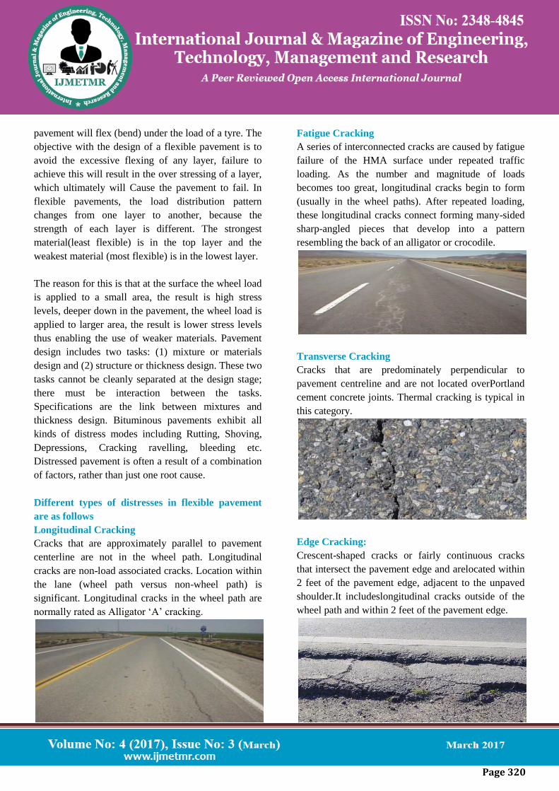
Longitudinal Cracking
Cracks that are approximately parallel to pavement
centerline are not in the wheel path. Longitudinal
cracks are non-load associated cracks. Location within
the lane (wheel path versus non-wheel path) is
significant. Longitudinal cracks in the wheel path are
normally rated as Alligator ‘A’ cracking.
Fatigue Cracking
A series of interconnected cracks are caused by fatigue
failure of the HMA surface under repeated traffic
loading. As the number and magnitude of loads
becomes too great, longitudinal cracks begin to form
(usually in the wheel paths). After repeated loading,
these longitudinal cracks connect forming many-sided
sharp-angled pieces that develop into a pattern
resembling the back of an alligator or crocodile.
Transverse Cracking
Cracks that are predominately perpendicular to
pavement centreline and are not located overPortland
cement concrete joints. Thermal cracking is typical in
this category.
Edge Cracking:
Crescent-shaped cracks or fairly continuous cracks
that intersect the pavement edge and arelocated within
2 feet of the pavement edge, adjacent to the unpaved
shoulder.It includeslongitudinal cracks outside of the
wheel path and within 2 feet of the pavement edge.
Page 321
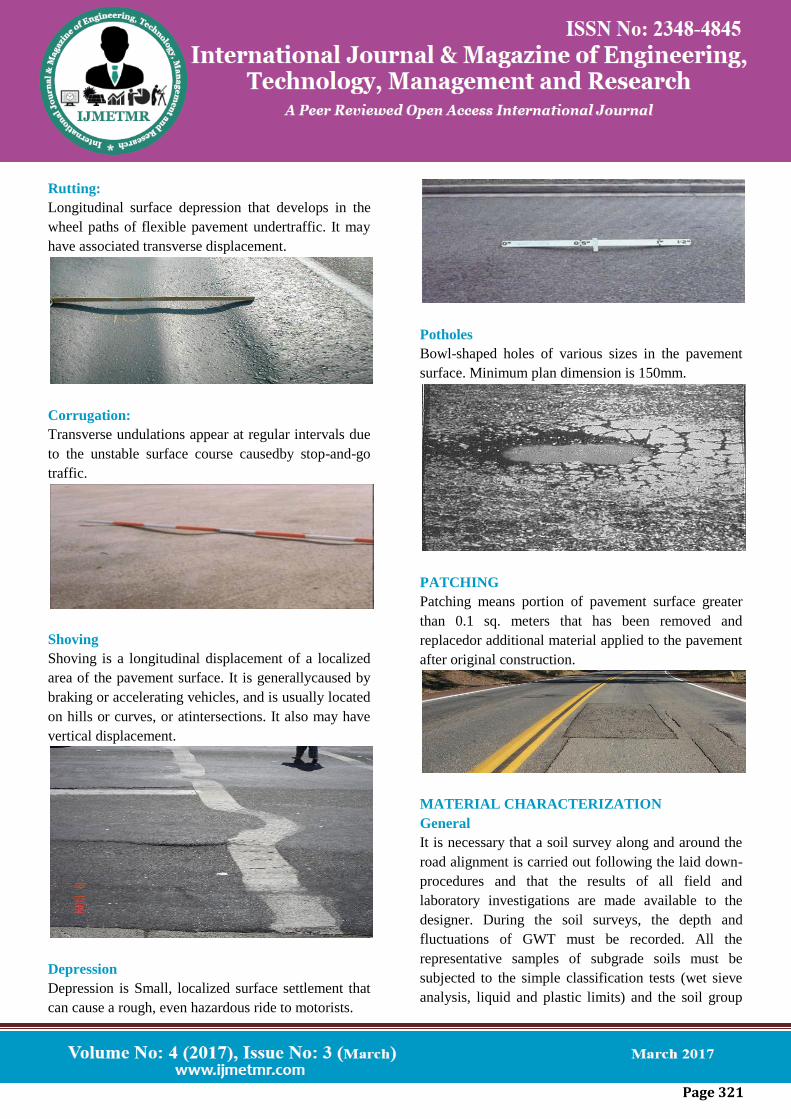
Rutting:
Longitudinal surface depression that develops in the
wheel paths of flexible pavement undertraffic. It may
have associated transverse displacement.
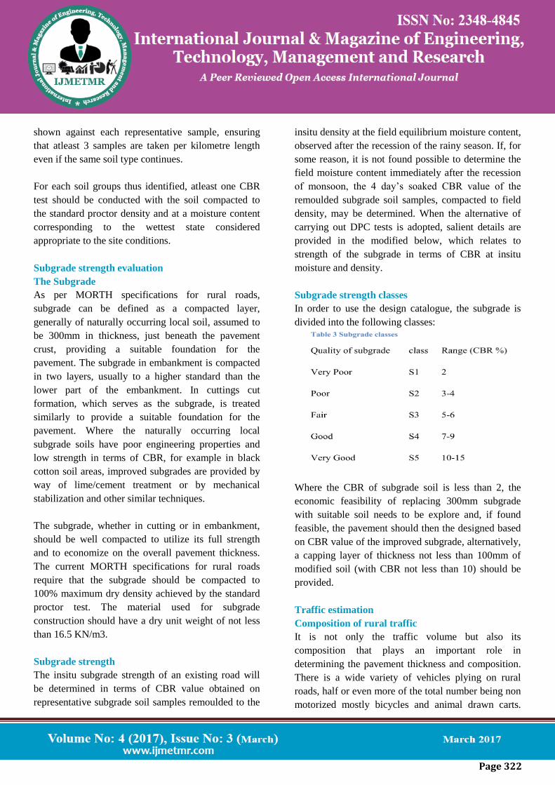
Corrugation:
Transverse undulations appear at regular intervals due
to the unstable surface course causedby stop-and-go
traffic.
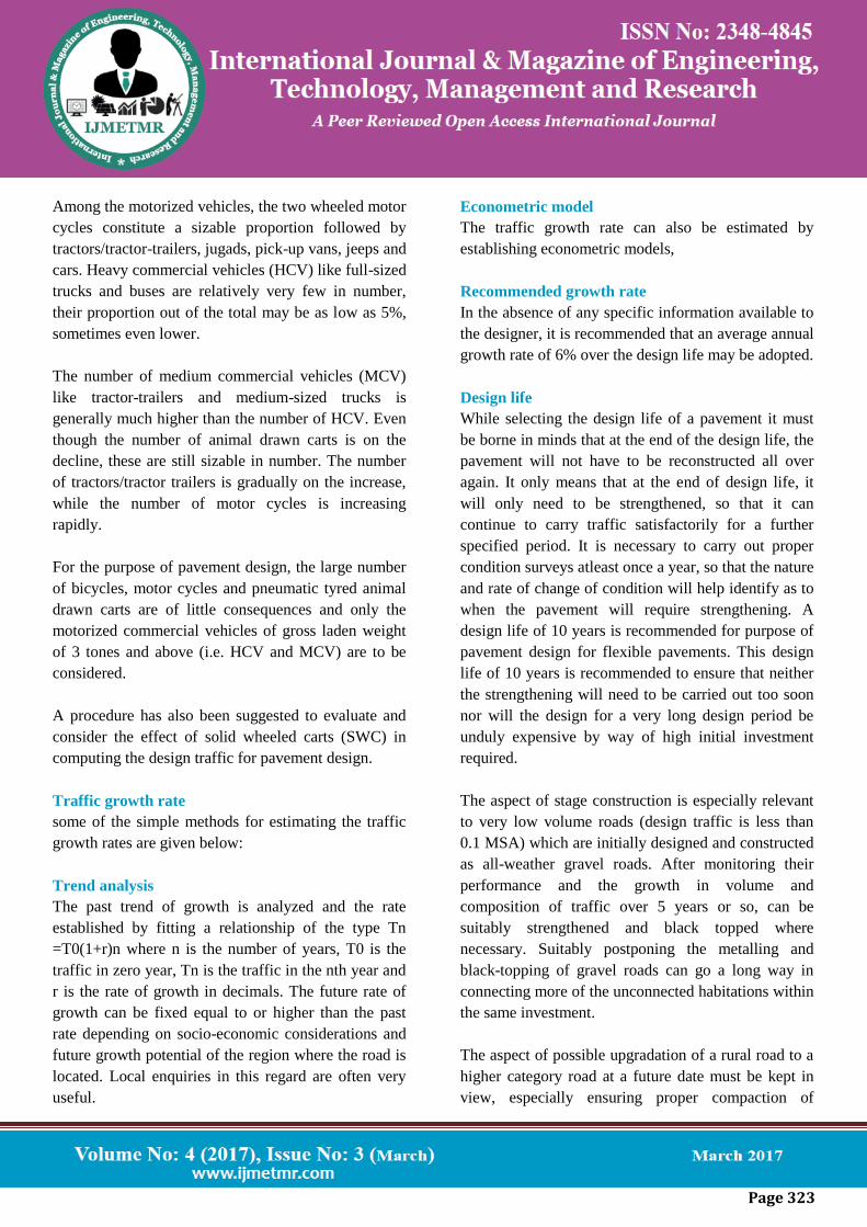
Shoving
Shoving is a longitudinal displacement of a localized
area of the pavement surface. It is generallycaused by
braking or accelerating vehicles, and is usually located
on hills or curves, or atintersections. It also may have
vertical displacement.
Depression
Depression is Small, localized surface settlement that
can cause a rough, even hazardous ride to motorists.
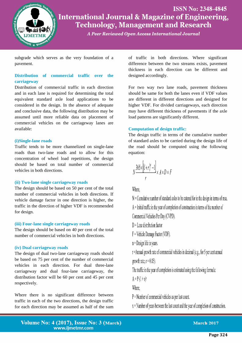
Potholes
Bowl-shaped holes of various sizes in the pavement
surface. Minimum plan dimension is 150mm.
PATCHING
Patching means portion of pavement surface greater
than 0.1 sq. meters that has been removed and
replacedor additional material applied to the pavement
after original construction.
MATERIAL CHARACTERIZATION
General
It is necessary that a soil survey along and around the
road alignment is carried out following the laid down-
procedures and that the results of all field and
laboratory investigations are made available to the
designer. During the soil surveys, the depth and
fluctuations of GWT must be recorded. All the
representative samples of subgrade soils must be
subjected to the simple classification tests (wet sieve
analysis, liquid and plastic limits) and the soil group
Page 322
shown against each representative sample, ensuring
that atleast 3 samples are taken per kilometre length
even if the same soil type continues.
For each soil groups thus identified, atleast one CBR
test should be conducted with the soil compacted to
the standard proctor density and at a moisture content
corresponding to the wettest state considered
appropriate to the site conditions.
Subgrade strength evaluation
The Subgrade
As per MORTH specifications for rural roads,
subgrade can be defined as a compacted layer,
generally of naturally occurring local soil, assumed to
be 300mm in thickness, just beneath the pavement
crust, providing a suitable foundation for the
pavement. The subgrade in embankment is compacted
in two layers, usually to a higher standard than the
lower part of the embankment. In cuttings cut
formation, which serves as the subgrade, is treated
similarly to provide a suitable foundation for the
pavement. Where the naturally occurring local
subgrade soils have poor engineering properties and
low strength in terms of CBR, for example in black
cotton soil areas, improved subgrades are provided by
way of lime/cement treatment or by mechanical
stabilization and other similar techniques.
The subgrade, whether in cutting or in embankment,
should be well compacted to utilize its full strength
and to economize on the overall pavement thickness.
The current MORTH specifications for rural roads
require that the subgrade should be compacted to
100% maximum dry density achieved by the standard
proctor test. The material used for subgrade
construction should have a dry unit weight of not less
than 16.5 KN/m3.
Subgrade strength
The insitu subgrade strength of an existing road will
be determined in terms of CBR value obtained on
representative subgrade soil samples remoulded to the
insitu density at the field equilibrium moisture content,
observed after the recession of the rainy season. If, for
some reason, it is not found possible to determine the
field moisture content immediately after the recession
of monsoon, the 4 day’s soaked CBR value of the
remoulded subgrade soil samples, compacted to field
density, may be determined. When the alternative of
carrying out DPC tests is adopted, salient details are
provided in the modified below, which relates to
strength of the subgrade in terms of CBR at insitu
moisture and density.
Subgrade strength classes
In order to use the design catalogue, the subgrade is
divided into the following classes:
Where the CBR of subgrade soil is less than 2, the
economic feasibility of replacing 300mm subgrade
with suitable soil needs to be explore and, if found
feasible, the pavement should then the designed based
on CBR value of the improved subgrade, alternatively,
a capping layer of thickness not less than 100mm of
modified soil (with CBR not less than 10) should be
provided.
Traffic estimation
Composition of rural traffic
It is not only the traffic volume but also its
composition that plays an important role in
determining the pavement thickness and composition.
There is a wide variety of vehicles plying on rural
roads, half or even more of the total number being non
motorized mostly bicycles and animal drawn carts.
Page 323
Among the motorized vehicles, the two wheeled motor
cycles constitute a sizable proportion followed by
tractors/tractor-trailers, jugads, pick-up vans, jeeps and
cars. Heavy commercial vehicles (HCV) like full-sized
trucks and buses are relatively very few in number,
their proportion out of the total may be as low as 5%,
sometimes even lower.
The number of medium commercial vehicles (MCV)
like tractor-trailers and medium-sized trucks is
generally much higher than the number of HCV. Even
though the number of animal drawn carts is on the
decline, these are still sizable in number. The number
of tractors/tractor trailers is gradually on the increase,
while the number of motor cycles is increasing
rapidly.
For the purpose of pavement design, the large number
of bicycles, motor cycles and pneumatic tyred animal
drawn carts are of little consequences and only the
motorized commercial vehicles of gross laden weight
of 3 tones and above (i.e. HCV and MCV) are to be
considered.
A procedure has also been suggested to evaluate and
consider the effect of solid wheeled carts (SWC) in
computing the design traffic for pavement design.
Traffic growth rate
some of the simple methods for estimating the traffic
growth rates are given below:
Trend analysis
The past trend of growth is analyzed and the rate
established by fitting a relationship of the type Tn
=T0(1+r)n where n is the number of years, T0 is the
traffic in zero year, Tn is the traffic in the nth year and
r is the rate of growth in decimals. The future rate of
growth can be fixed equal to or higher than the past
rate depending on socio-economic considerations and
future growth potential of the region where the road is
located. Local enquiries in this regard are often very
useful.
Econometric model
The traffic growth rate can also be estimated by
establishing econometric models,
Recommended growth rate
In the absence of any specific information available to
the designer, it is recommended that an average annual
growth rate of 6% over the design life may be adopted.
Design life
While selecting the design life of a pavement it must
be borne in minds that at the end of the design life, the
pavement will not have to be reconstructed all over
again. It only means that at the end of design life, it
will only need to be strengthened, so that it can
continue to carry traffic satisfactorily for a further
specified period. It is necessary to carry out proper
condition surveys atleast once a year, so that the nature
and rate of change of condition will help identify as to
when the pavement will require strengthening. A
design life of 10 years is recommended for purpose of
pavement design for flexible pavements. This design
life of 10 years is recommended to ensure that neither
the strengthening will need to be carried out too soon
nor will the design for a very long design period be
unduly expensive by way of high initial investment
required.
The aspect of stage construction is especially relevant
to very low volume roads (design traffic is less than
0.1 MSA) which are initially designed and constructed
as all-weather gravel roads. After monitoring their
performance and the growth in volume and
composition of traffic over 5 years or so, can be
suitably strengthened and black topped where
necessary. Suitably postponing the metalling and
black-topping of gravel roads can go a long way in
connecting more of the unconnected habitations within
the same investment.
The aspect of possible upgradation of a rural road to a
higher category road at a future date must be kept in
view, especially ensuring proper compaction of
Page 324
subgrade which serves as the very foundation of a
pavement.
Distribution of commercial traffic over the
carriageway
Distribution of commercial traffic in each direction
and in each lane is required for determining the total
equivalent standard axle load applications to be
considered in the design. In the absence of adequate
and conclusive data, the following distribution may be
assumed until more reliable data on placement of
commercial vehicles on the carriageway lanes are
available:
(i)Single-lane roads
Traffic tends to be more channelized on single-lane
roads than two-lane roads and to allow for this
concentration of wheel load repetitions, the design
should be based on total number of commercial
vehicles in both directions.
(ii) Two-lane single carriageway roads
The design should be based on 50 per cent of the total
number of commercial vehicles in both directions. If
vehicle damage factor in one direction is higher, the
traffic in the direction of higher VDF is recommended
for design.
(iii) Four-lane single carriageway roads
The design should be based on 40 per cent of the total
number of commercial vehicles in both directions.
(iv) Dual carriageway roads
The design of dual two-lane carriageway roads should
be based on 75 per cent of the number of commercial
vehicles in each direction. For dual three-lane
carriageway and dual four-lane carriageway, the
distribution factor will be 60 per cent and 45 per cent
respectively.
Where there is no significant difference between
traffic in each of the two directions, the design traffic
for each direction may be assumed as half of the sum
of traffic in both directions. Where significant
difference between the two streams exists, pavement
thickness in each direction can be different and
designed accordingly.
For two way two lane roads, pavement thickness
should be same for both the lanes even if VDF values
are different in different directions and designed for
higher VDF. For divided carriageways, each direction
may have different thickness of pavements if the axle
load patterns are significantly different.
Computation of design traffic:
The design traffic in terms of the cumulative number
of standard axles to be carried during the design life of
the road should be computed using the following
equation:
Page 325
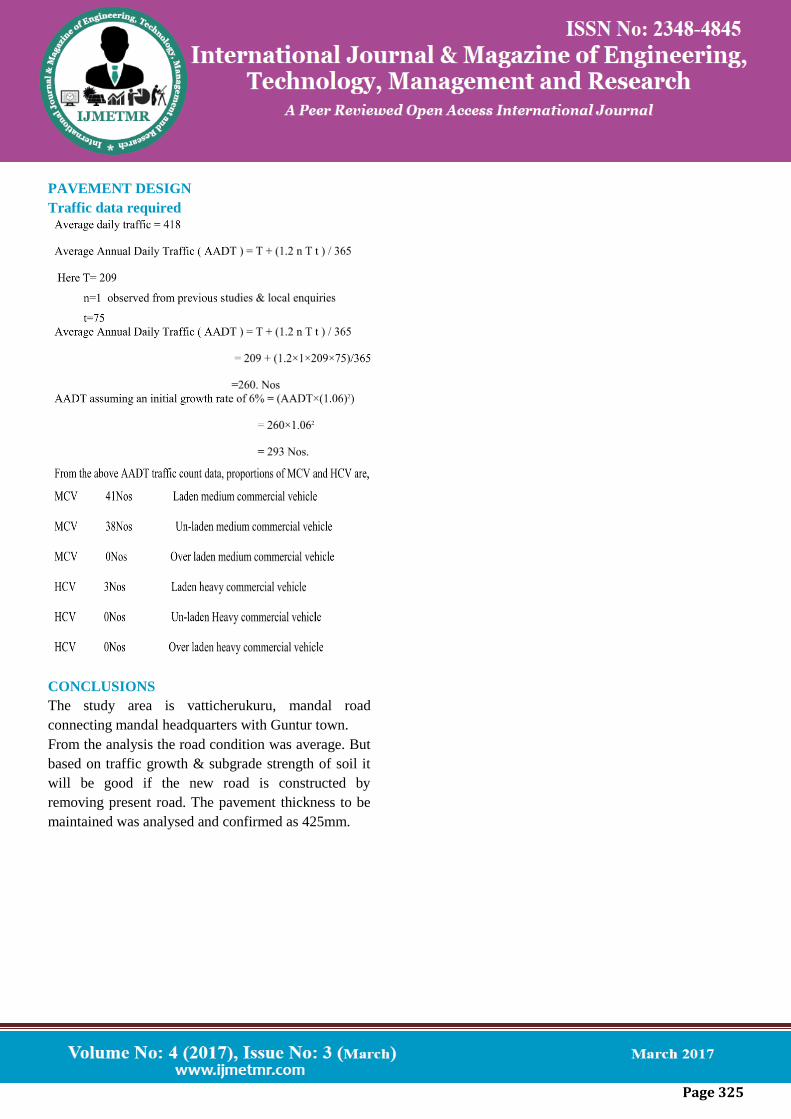
PAVEMENT DESIGN
Traffic data required
CONCLUSIONS
The study area is vatticherukuru, mandal road
connecting mandal headquarters with Guntur town.
From the analysis the road condition was average. But
based on traffic growth & subgrade strength of soil it
will be good if the new road is constructed by
removing present road. The pavement thickness to be
maintained was analysed and confirmed as 425mm.