Embed Size (px)
Citation preview
Page 1The present publication reflects only the author’s views and the FCH JU and the Union
are not liable for any use that may be made of the information contained therein.
Flexible Hybrid separation system for
H2 recovery from NG Grids
HyGrid
This project has received funding from the Fuel Cells and Hydrogen 2 Joint Undertaking under grantagreement No 700355. This Joint Undertaking receives support from the European Union’s Horizon 2020
research and innovation programme and Hydrogen Europe and N.ERGHY
Duration: 3 years. Starting date: 01-May-2016
Contacts: [email protected]
The present publication reflects only the author’s views and the FCH JU and the Union
are not liable for any use that may be made of the information contained therein.
https://www.hygrid-h2.eu/
Ref. Ares(2020)1619399 - 17/03/2020
Page 2The present publication reflects only the author’s views and the FCH JU and the Union
are not liable for any use that may be made of the information contained therein.
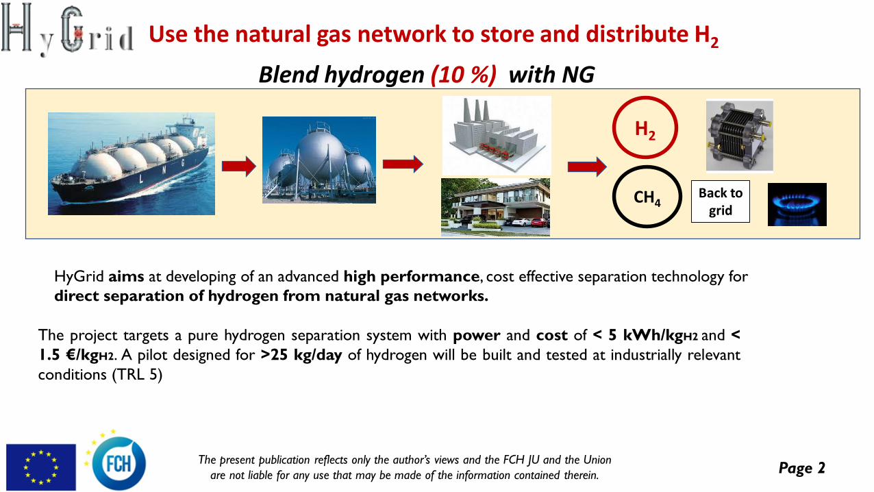
Blend hydrogen (10 %) with NG
Use the natural gas network to store and distribute H2
H2
CH4Back to
grid
HyGrid aims at developing of an advanced high performance, cost effective separation technology for
direct separation of hydrogen from natural gas networks.
The project targets a pure hydrogen separation system with power and cost of < 5 kWh/kgH2 and <
1.5 €/kgH2. A pilot designed for >25 kg/day of hydrogen will be built and tested at industrially relevant
conditions (TRL 5)
Page 3The present publication reflects only the author’s views and the FCH JU and the Union
are not liable for any use that may be made of the information contained therein.
General concept
HyGrid aims at developing of an advanced high performance, cost effective separation technology for
direct separation of hydrogen from natural gas networks.
The system will be based on:
➢ Design, construction and testing of an novel membrane based hybrid technology for pure hydrogen
production (ISO 14687) combining three technologies for hydrogen purification integrated in a way that
enhances the strengths of each of them: membrane separation technology is employed for removing
H2 from the “low H2 content” (e.g. 2-10 %) followed by electrochemical hydrogen separation (EHP )
optimal for the “very low H2 content” (e.g. <2 %) and finally temperature swing adsorption (TSA)
technology to purify from humidity produced in both systems upstream.
➢ The project targets a pure hydrogen separation system with power and cost of < 5 kWh/kgH2 and <
1.5 €/kgH2. A pilot designed for >25 kg/day of hydrogen will be built and tested at industrially relevant
conditions (TRL 5).
Page 4The present publication reflects only the author’s views and the FCH JU and the Union
are not liable for any use that may be made of the information contained therein.
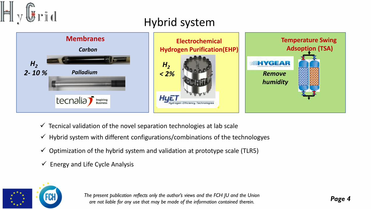
Temperature Swing Adsoption (TSA)
Removehumidity
ElectrochemicalHydrogen Purification(EHP)
H2
< 2%Palladium
Carbon
Membranes
H2
2- 10 %
Hybrid system
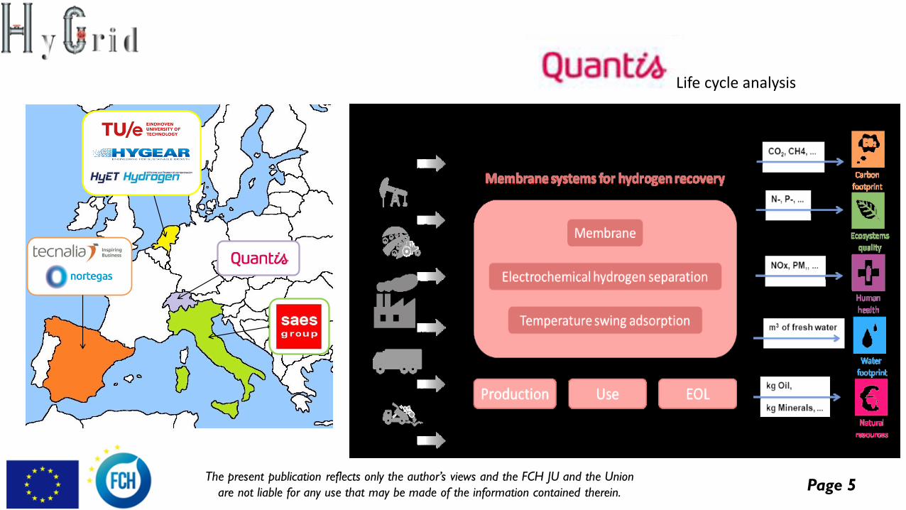
✓ Tecnical validation of the novel separation technologies at lab scale
✓ Optimization of the hybrid system and validation at prototype scale (TLR5)
✓ Hybrid system with different configurations/combinations of the technologyes
✓ Energy and Life Cycle Analysis
Page 5The present publication reflects only the author’s views and the FCH JU and the Union
are not liable for any use that may be made of the information contained therein.
Life cycle analysis
Page 6The present publication reflects only the author’s views and the FCH JU and the Union
are not liable for any use that may be made of the information contained therein.
Membrane development
Objective
Development of cost effective tubular supported membranes for the recovery of hydrogen from
low concentration streams (2% -10%) in the whole range of pressures of the Natural Gas Network
✓ Pd-based membranes for the medium to the lowest Natural Gas Grid pressures.
✓ Carbon Molecular Sieve membranes for the high pressure range.
✓ Membrane module for the prototype.
Page 7The present publication reflects only the author’s views and the FCH JU and the Union
are not liable for any use that may be made of the information contained therein.
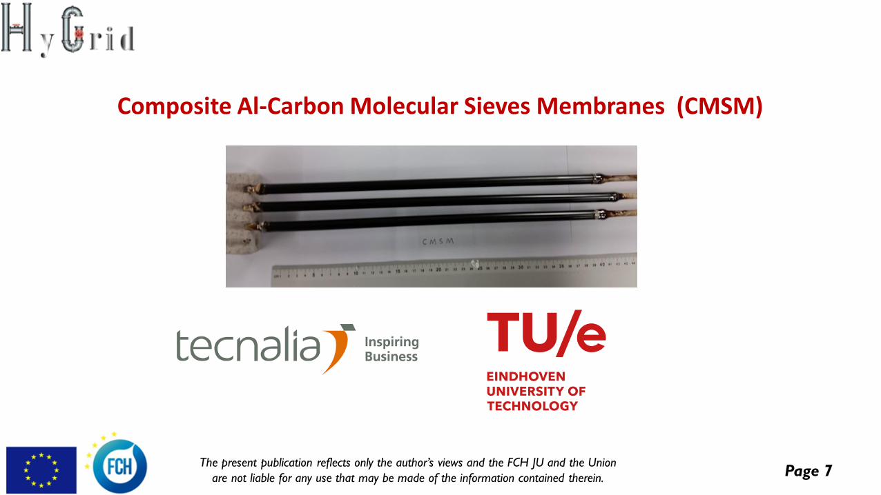
Composite Al-Carbon Molecular Sieves Membranes (CMSM)
Page 8The present publication reflects only the author’s views and the FCH JU and the Union
are not liable for any use that may be made of the information contained therein.
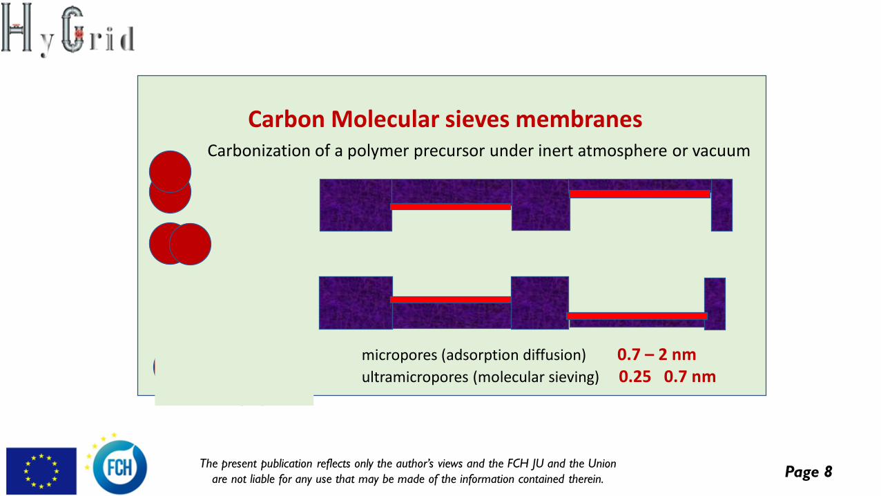
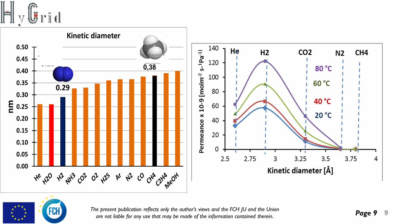
Carbon Molecular sieves membranesCarbonization of a polymer precursor under inert atmosphere or vacuum
micropores (adsorption diffusion) 0.7 – 2 nm ultramicropores (molecular sieving) 0.25 0.7 nm
Page 9The present publication reflects only the author’s views and the FCH JU and the Union
are not liable for any use that may be made of the information contained therein. 9
Page 10The present publication reflects only the author’s views and the FCH JU and the Union
are not liable for any use that may be made of the information contained therein.
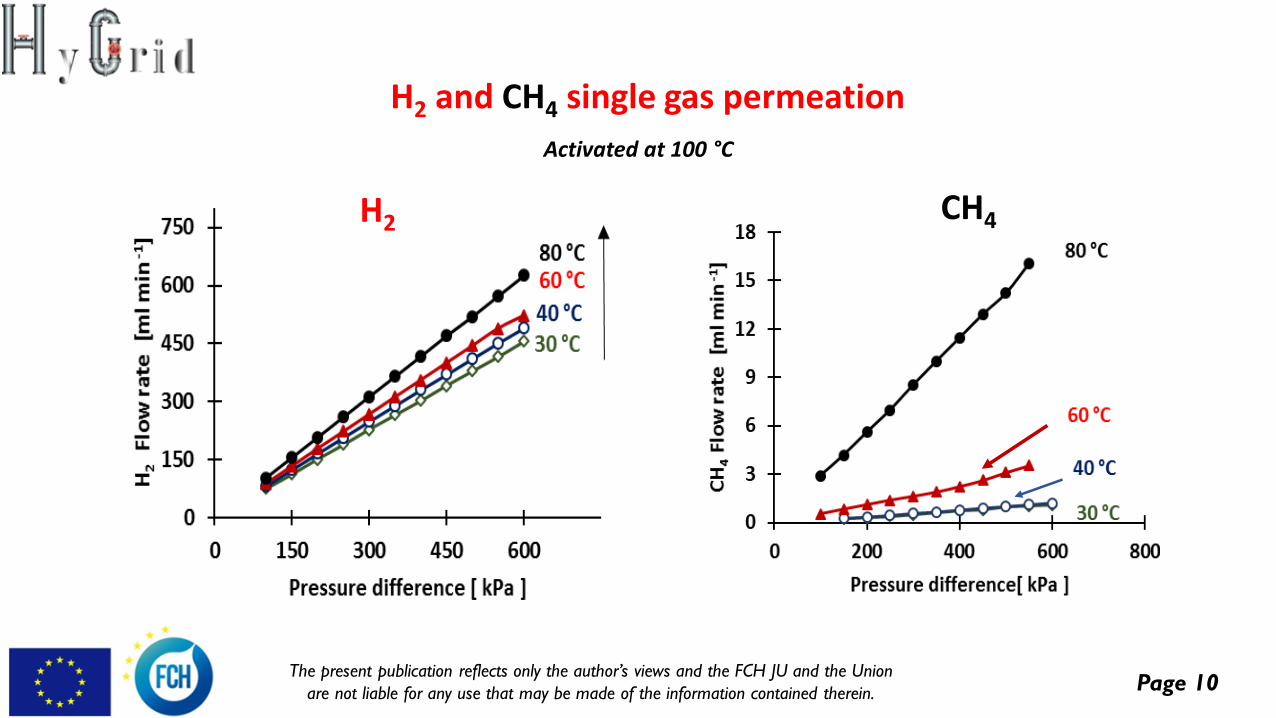
H2 and CH4 single gas permeation
H2
Activated at 100 °C
CH4
Page 11The present publication reflects only the author’s views and the FCH JU and the Union
are not liable for any use that may be made of the information contained therein.
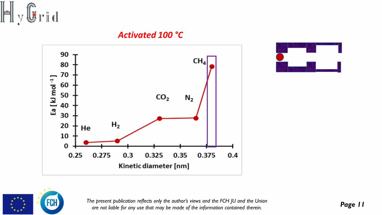
Activated 100 °C
Page 12The present publication reflects only the author’s views and the FCH JU and the Union
are not liable for any use that may be made of the information contained therein.
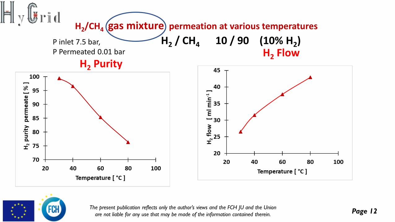
H2/CH4 gas mixture permeation at various temperatures
P inlet 7.5 bar, P Permeated 0.01 bar
H2 / CH4 10 / 90 (10% H2)
H2 PurityH2 Flow
Page 13The present publication reflects only the author’s views and the FCH JU and the Union
are not liable for any use that may be made of the information contained therein.
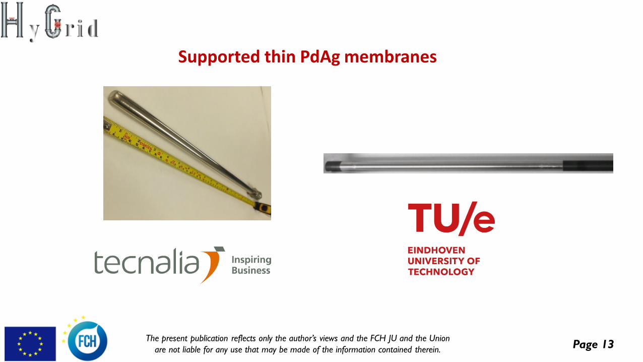
Supported thin PdAg membranes
Page 14The present publication reflects only the author’s views and the FCH JU and the Union
are not liable for any use that may be made of the information contained therein.
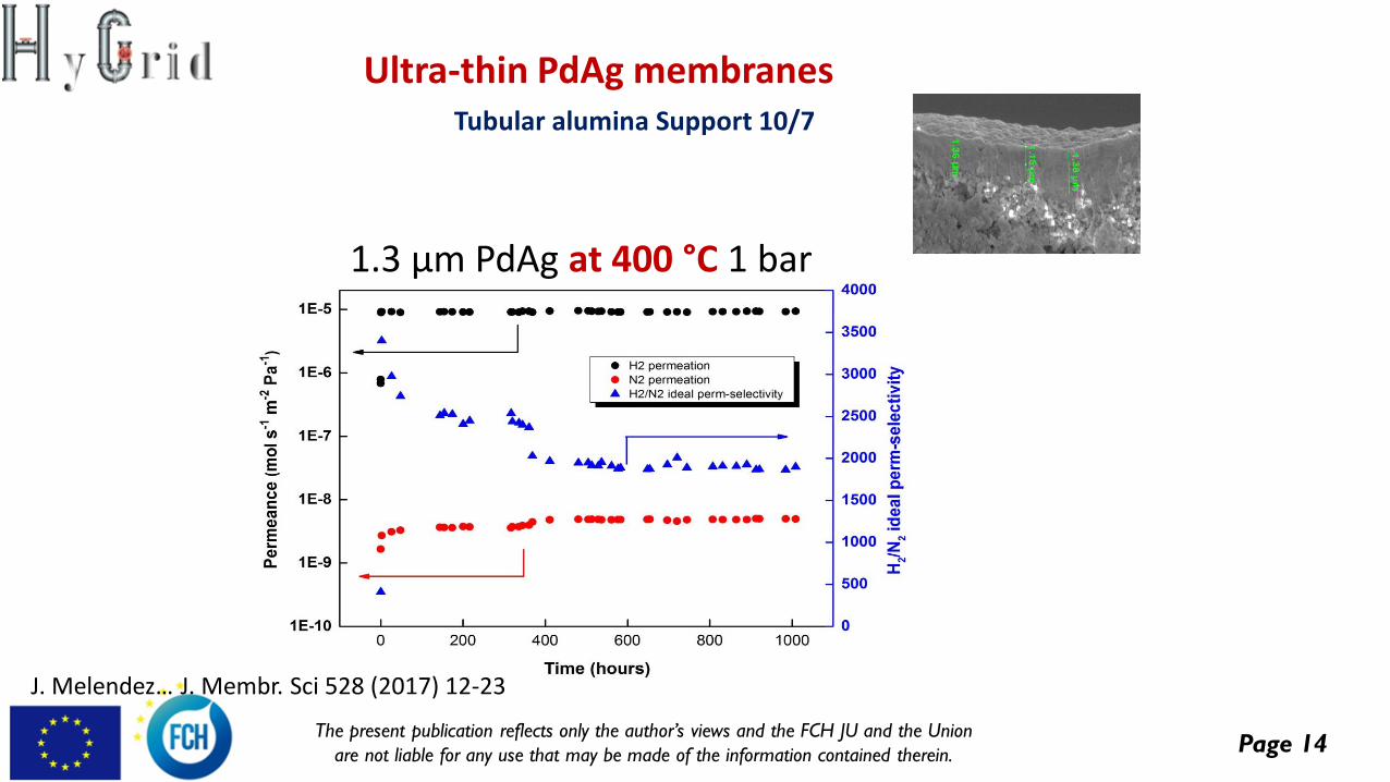
Ultra-thin PdAg membranes
1.3 µm PdAg at 400 °C 1 bar
Tubular alumina Support 10/7
J. Melendez… J. Membr. Sci 528 (2017) 12-23
Page 15The present publication reflects only the author’s views and the FCH JU and the Union
are not liable for any use that may be made of the information contained therein.
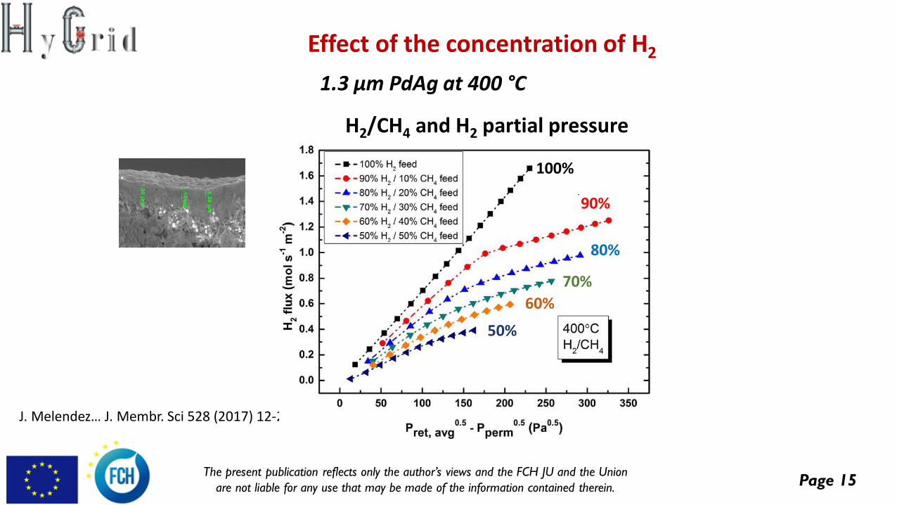
1.3 µm PdAg at 400 °C
Effect of the concentration of H2
J. Melendez… J. Membr. Sci 528 (2017) 12-23
H2/CH4 and H2 partial pressure
100%
90%
80%
70%
60%
50%
Page 16The present publication reflects only the author’s views and the FCH JU and the Union
are not liable for any use that may be made of the information contained therein.
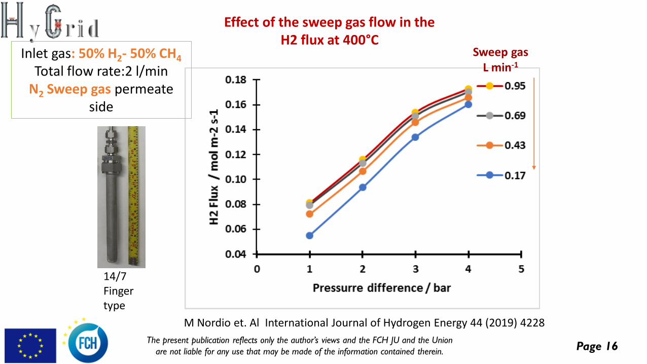
Sweep gasL min-1
14/7Fingertype
Inlet gas: 50% H2- 50% CH4
Total flow rate:2 l/minN2 Sweep gas permeate
side
Effect of the sweep gas flow in theH2 flux at 400°C
M Nordio et. Al International Journal of Hydrogen Energy 44 (2019) 4228
Page 17The present publication reflects only the author’s views and the FCH JU and the Union
are not liable for any use that may be made of the information contained therein.
Electrochemical hydrogen separation
development
Objectives:
Development of an electrochemical hydrogen purifier (EHP) for the
recovery of the hydrogen from very low concentration streams (≤ 2 %).
➢ Capable of recovering the majority of the remaining hydrogen from the
retentate of the membrane separator.
➢ Optimum configuration of membrane-electrode-assembly for low
concentration hydrogen extraction.
➢ Theoretical modelling assisted optimum design of stack and gas
distribution plate geometry for low concentration electrochemical
hydrogen extraction (<3%).
➢ Construction and testing of sub- and full size electrochemical
compressor stacks for model validation and prototype preparation.
Page 18The present publication reflects only the author’s views and the FCH JU and the Union
are not liable for any use that may be made of the information contained therein.
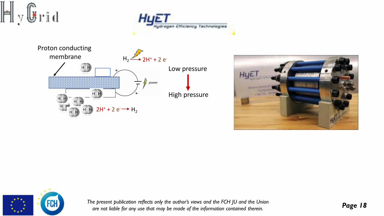
+ + -- H2 2H+ + 2 e-
2H+ + 2 e- H2
Proton conductingmembrane
Low pressure
High pressure
Page 19The present publication reflects only the author’s views and the FCH JU and the Union
are not liable for any use that may be made of the information contained therein.
Electrochemical hydrogen separation
development
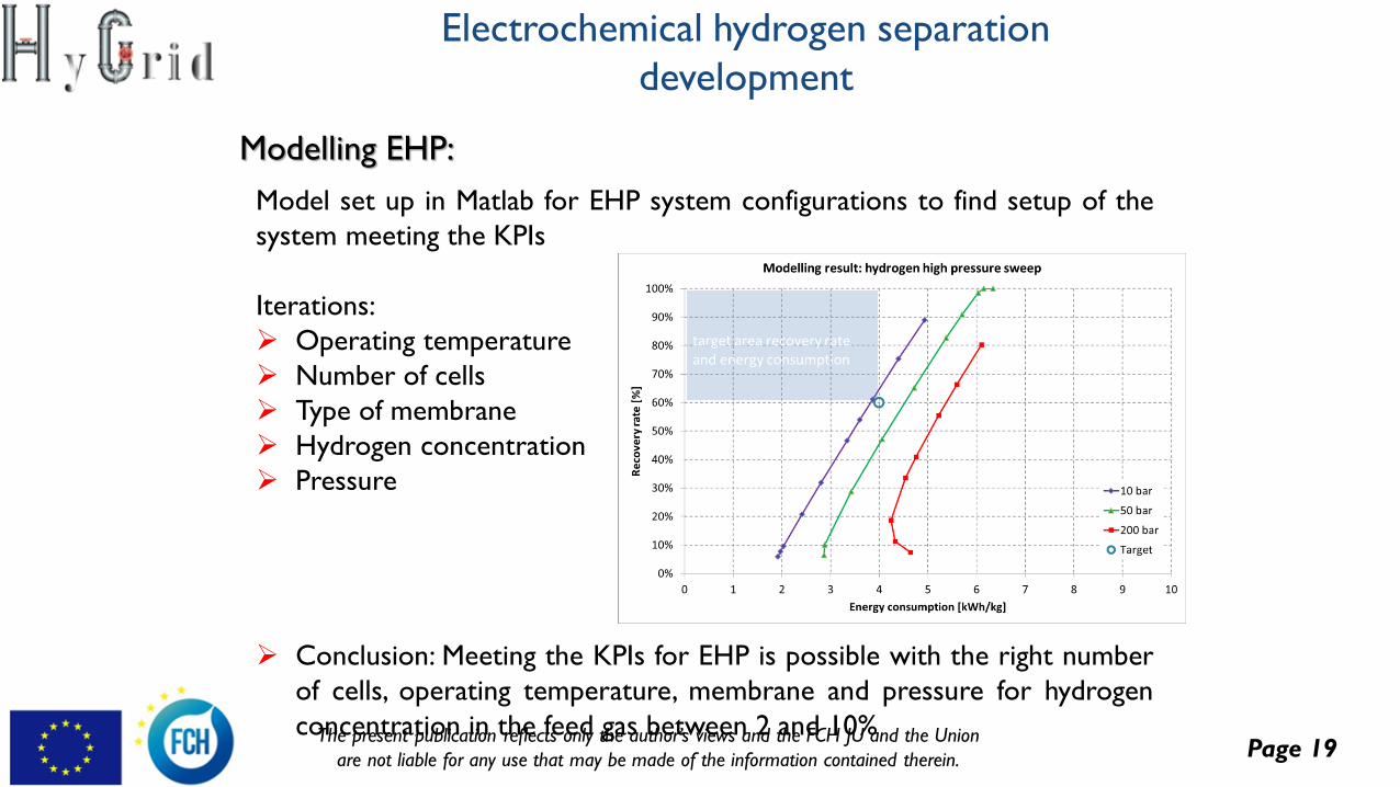
Modelling EHP:
Model set up in Matlab for EHP system configurations to find setup of the
system meeting the KPIs
Iterations:
➢ Operating temperature
➢ Number of cells
➢ Type of membrane
➢ Hydrogen concentration
➢ Pressure
➢ Conclusion: Meeting the KPIs for EHP is possible with the right number
of cells, operating temperature, membrane and pressure for hydrogen
concentration in the feed gas between 2 and 10%
Page 20The present publication reflects only the author’s views and the FCH JU and the Union
are not liable for any use that may be made of the information contained therein.
Electrochemical hydrogen separation
development
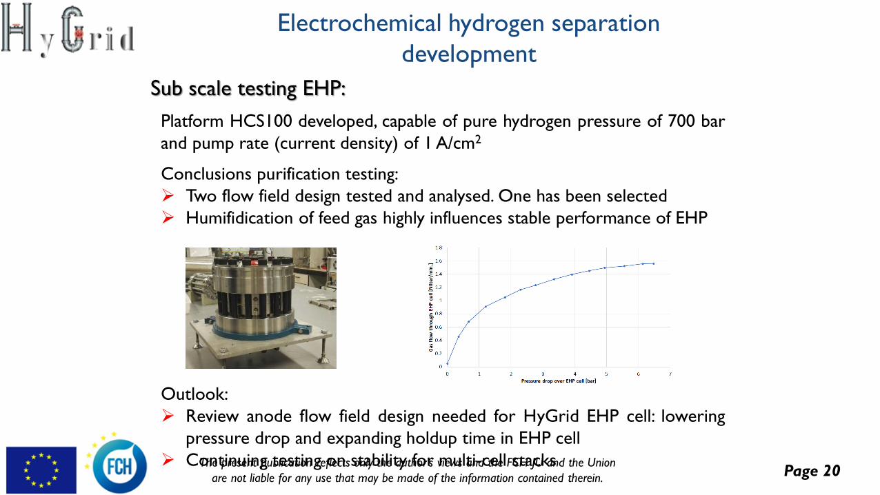
Sub scale testing EHP:
Platform HCS100 developed, capable of pure hydrogen pressure of 700 bar
and pump rate (current density) of 1 A/cm2
Conclusions purification testing:
➢ Two flow field design tested and analysed. One has been selected
➢ Humifidication of feed gas highly influences stable performance of EHP
Outlook:
➢ Review anode flow field design needed for HyGrid EHP cell: lowering
pressure drop and expanding holdup time in EHP cell
➢ Continuing testing on stability for multi-cell stacks
Page 21The present publication reflects only the author’s views and the FCH JU and the Union
are not liable for any use that may be made of the information contained therein.
Electrochemical hydrogen separation
development
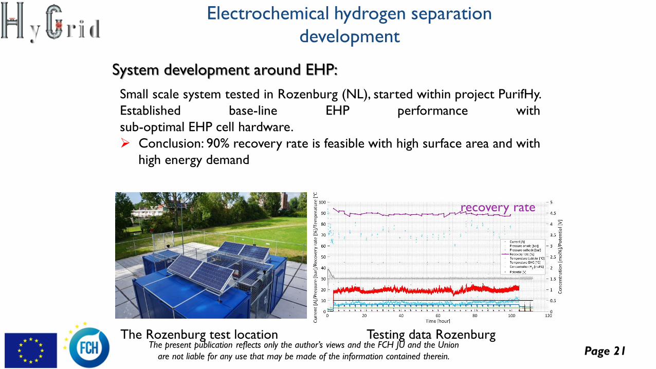
System development around EHP:
Small scale system tested in Rozenburg (NL), started within project PurifHy.
Established base-line EHP performance with
sub-optimal EHP cell hardware.
➢ Conclusion: 90% recovery rate is feasible with high surface area and with
high energy demand
recovery rate
The Rozenburg test location Testing data Rozenburg
Page 22The present publication reflects only the author’s views and the FCH JU and the Union
are not liable for any use that may be made of the information contained therein.
Temperature Swing Adsorption
development
Objectives:
Design, construction and test of the TSA unit.
➢ Better comprehension of the behaviour and performance of the
adsorption materials used in TSA.
➢ Understanding of the response of adsorbents to the dynamic
temperature control.
➢ Implementation of the know-how gained through lab tests onto the up-
scaled design.
➢ Design of prototype TSA unit for integration in pilot scale HyGrid
system.
➢ Testing of pilot scale TSA unit.
Page 23The present publication reflects only the author’s views and the FCH JU and the Union
are not liable for any use that may be made of the information contained therein.
Development of TSA strategy and
sizing
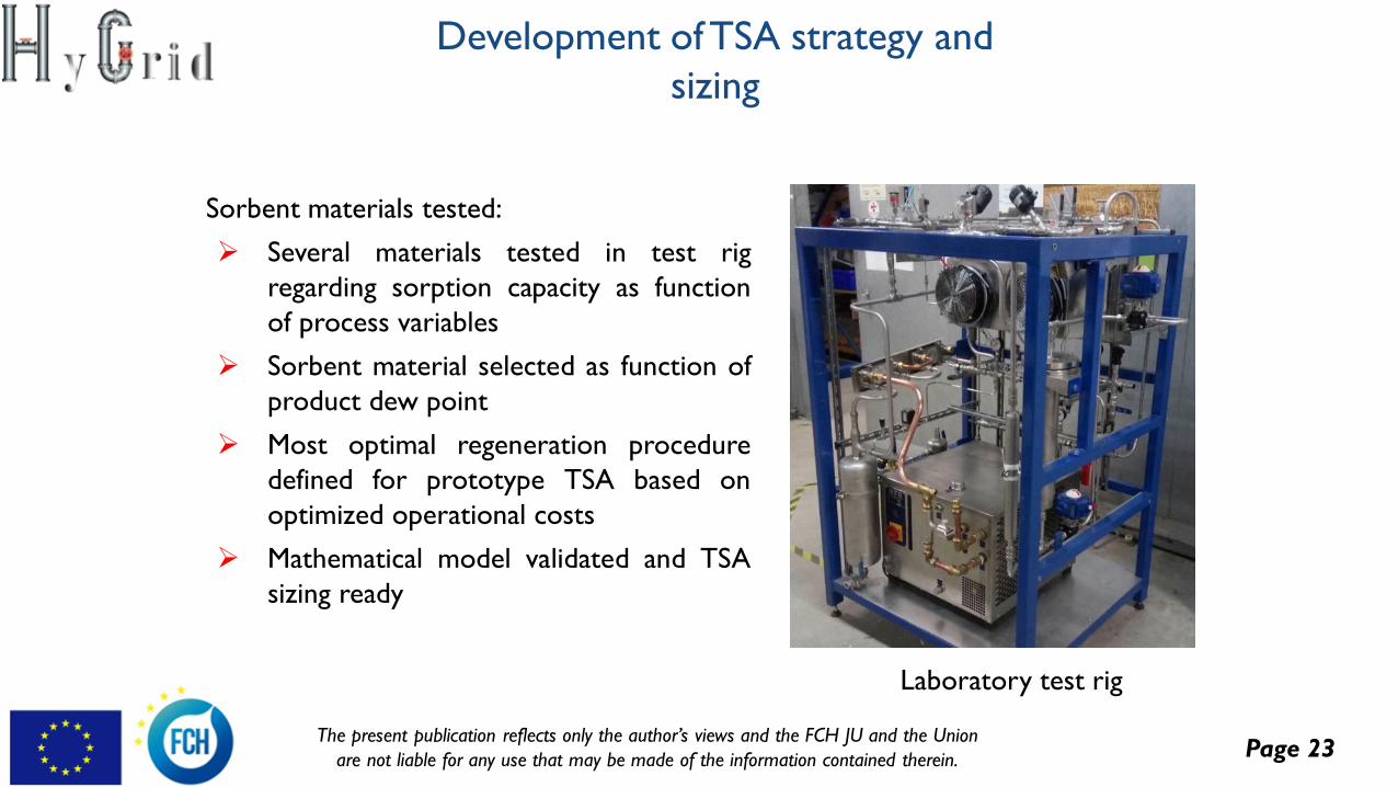
Sorbent materials tested:
➢ Several materials tested in test rig
regarding sorption capacity as function
of process variables
➢ Sorbent material selected as function of
product dew point
➢ Most optimal regeneration procedure
defined for prototype TSA based on
optimized operational costs
➢ Mathematical model validated and TSA
sizing ready
Laboratory test rig
Page 24The present publication reflects only the author’s views and the FCH JU and the Union
are not liable for any use that may be made of the information contained therein.
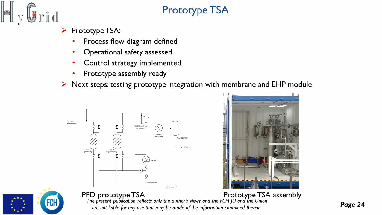
Prototype TSA
➢ Prototype TSA:
• Process flow diagram defined
• Operational safety assessed
• Control strategy implemented
• Prototype assembly ready
➢ Next steps: testing prototype integration with membrane and EHP module
Ads 1(producing)
Ads 2(regenerating)
Feed
Heater
Product
Cooler/condenser
Regeneration gas compressor
G/L separator
Water
cooling
heati ng
Regeneration gas
PFD prototype TSA Prototype TSA assembly
Page 25The present publication reflects only the author’s views and the FCH JU and the Union
are not liable for any use that may be made of the information contained therein.
Lab scale testing
Objectives:
Design and test a small version of the prototype and test it at lab scale
especially in conditions not feasible for the prototype.
➢ Investigate the recovery of the membrane system at different pressures
and different concentrations of hydrogen.
➢ Sorbents for the TSA selected will be further studied in TGA
experiments to evaluate the cyclic sorbent capacity and adsorption
isotherms.
➢ Evaluation of different configurations to identify the optimum separation
system along the natural gas network.
Page 26The present publication reflects only the author’s views and the FCH JU and the Union
are not liable for any use that may be made of the information contained therein.
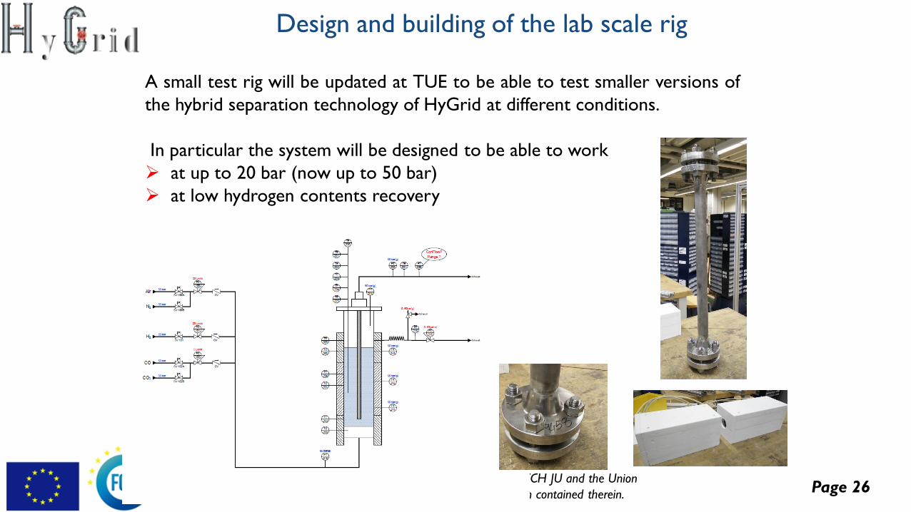
A small test rig will be updated at TUE to be able to test smaller versions of
the hybrid separation technology of HyGrid at different conditions.
In particular the system will be designed to be able to work
➢ at up to 20 bar (now up to 50 bar)
➢ at low hydrogen contents recovery
Design and building of the lab scale rig
Page 27The present publication reflects only the author’s views and the FCH JU and the Union
are not liable for any use that may be made of the information contained therein.
0.03
0.08
0.13
0.18
0.23
0.28
35 85 135 185
Hydro
gen r
ecovery
facto
r [-
]
Hydrogen partial pressure [Pa0.5]
0.3 l/min sweep gas
0.5 l/min sweep gas
0.7 l/min sweep gas
1 l/min sweep gas
1.5 l/min sweep gas
2 l/min sweep gas
3 l/min sweep gas
0
0.2
0.4
0.6
0.8
1
1.2
1.4
1.6
1.8
2
0 100 200 300 400
Hydro
gen
perm
eation [m
ol/s/m
2]
Hydrogen partial pressure [Pa0.5]
T=418C ultra-thin E635T=382C ultra-thin E635T=426C ultra-thin E633T=370C ultra-thin E633T=427C ultra-thin E689T=391 C ultra-thin E689
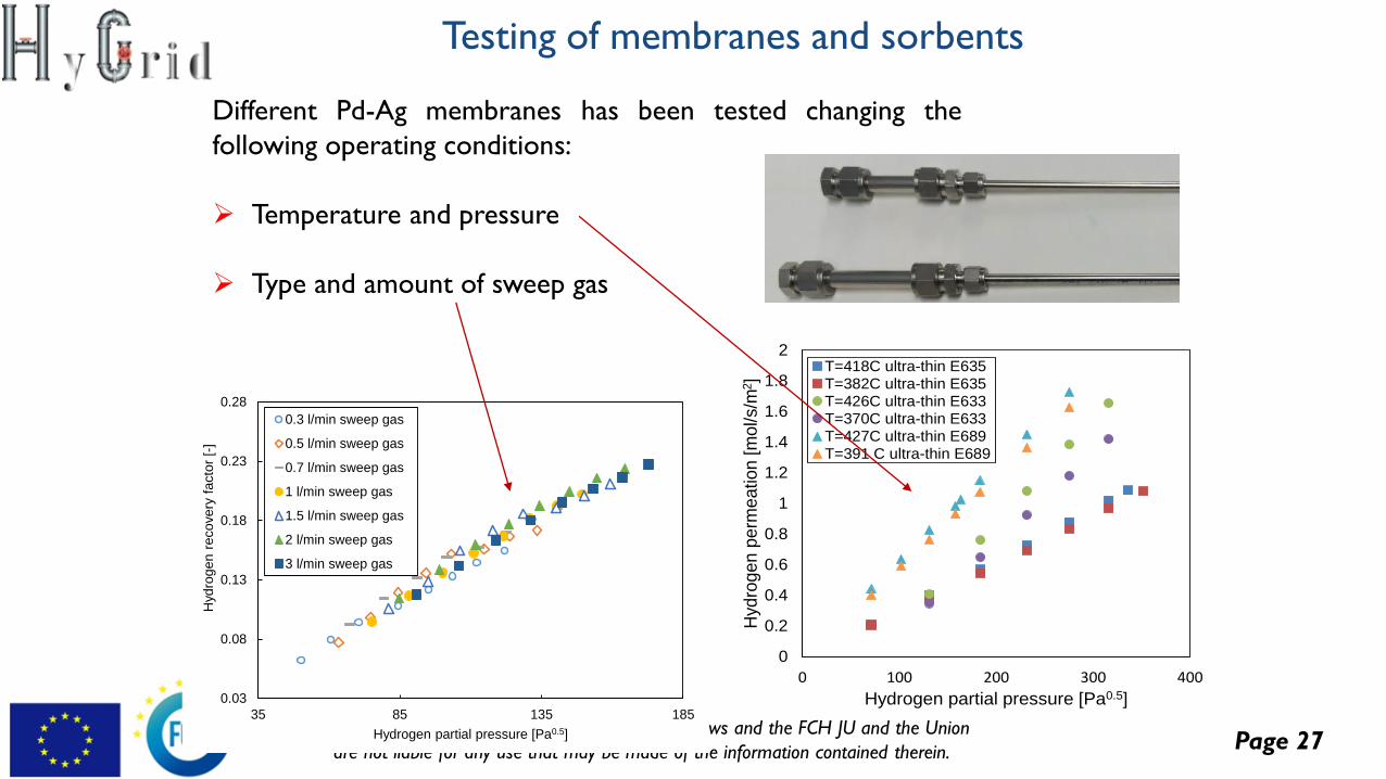
Different Pd-Ag membranes has been tested changing the
following operating conditions:
➢ Temperature and pressure
➢ Type and amount of sweep gas
Testing of membranes and sorbents
Page 28The present publication reflects only the author’s views and the FCH JU and the Union
are not liable for any use that may be made of the information contained therein.
0.04
0.06
0.08
0.1
0.12
0.14
0 2000 4000 6000 8000 10000 12000 14000H
2 p
erm
eate
[l/m
in]
Logarithmic partial pressure [Pa]
10% H2 1.5l/min sweepgas10% H21l/min sweepgas10% H2 0.8l/min sweepgas10% H2 0.9l/min sweepgas
0
500
1000
1500
2000
2500
3000
3500
0 200 400 600 800 1000 1200
H2 p
erm
ea
tio
n [m
l/m
in]
pressure difference [Pa0.58]
70%CH4 30%H2
60%CH4 40% H2
50%CH4 50%H2
40%CH4 60%H2
30%CH4 70%H2
20%CH4 80%H2
10%CH4 90%H2
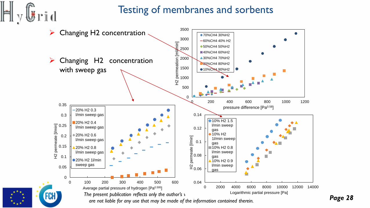
➢ Changing H2 concentration
➢ Changing H2 concentration
with sweep gas
0
0.05
0.1
0.15
0.2
0.25
0.3
0.35
0 100 200 300 400 500 600
H2 p
erm
eate
[l/m
in]
Average partial pressure of hydrogen [Pa0.595]
20% H2 0.3l/min sweep gas
20% H2 0.4l/min sweep gas
20% H2 0.6l/min sweep gas
20% H2 0.8l/min sweep gas
20% H2 1l/minsweep gas
Testing of membranes and sorbents
Page 29The present publication reflects only the author’s views and the FCH JU and the Union
are not liable for any use that may be made of the information contained therein.
0.0000
0.0200
0.0400
0.0600
0.0800
0.1000
0.1200
0.1400
0.1600
0.1800
0.2000
0.0000 0.0100 0.0200 0.0300 0.0400 0.0500 0.0600
we
igh
t d
iffe
rence
[-]
H2O partial pressure [bar]
45C silica
55C silica
65C silica
45C zeolite 4A
55C zeolite 4A
65C zeolite 4A
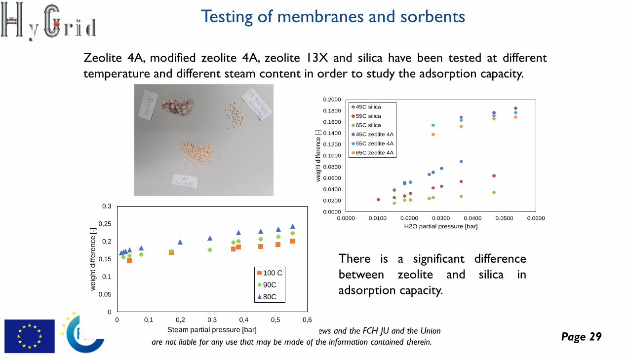
Zeolite 4A, modified zeolite 4A, zeolite 13X and silica have been tested at different
temperature and different steam content in order to study the adsorption capacity.
0
0,05
0,1
0,15
0,2
0,25
0,3
0 0,1 0,2 0,3 0,4 0,5 0,6
we
igh
t d
iffe
rence
[-]
Steam partial pressure [bar]
100 C
90C
80C
There is a significant difference
between zeolite and silica in
adsorption capacity.
Testing of membranes and sorbents
Page 30The present publication reflects only the author’s views and the FCH JU and the Union
are not liable for any use that may be made of the information contained therein.
Prototype integration and validation
Objectives:
➢Design of the integrated hydrogen recovery pilot plant
➢Construct and assemble the hydrogen recovery pilot plant including controls
➢Testing and assessment of hydrogen recovery pilot plant
Page 31The present publication reflects only the author’s views and the FCH JU and the Union
are not liable for any use that may be made of the information contained therein.
System modelling and simulation
Objectives:
To assess the energy analysis, and economic performance (in terms of
primary energy consumption and cost of pure H2) of the HyGrid system for
H2 separation from NG grid.
➢ Membrane module model and simulation.
➢ Development of dynamic model for TSA.
➢ Modelling of electrochemical separation and compression.
➢ Simulation and economic optimization of integrated hydrogen recovery
Page 32The present publication reflects only the author’s views and the FCH JU and the Union
are not liable for any use that may be made of the information contained therein.
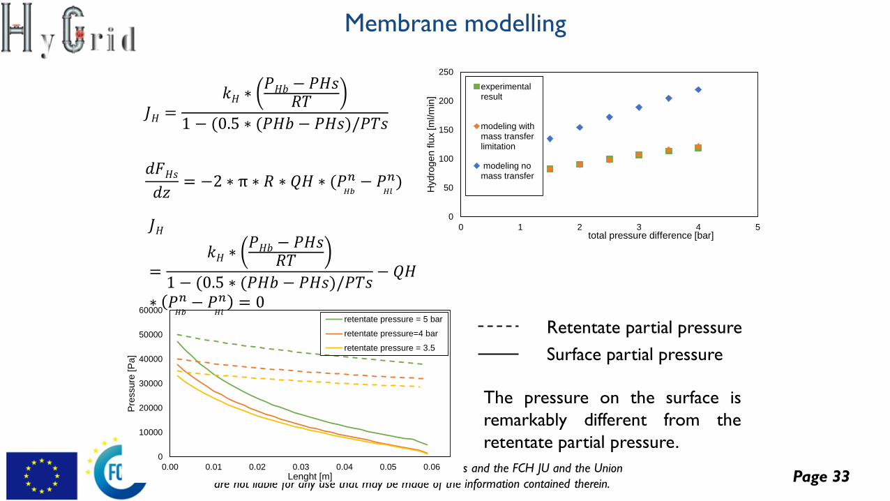
PHb
H2 partial
pressure in
the bulk
PHl
Hydrogen partial
pressure in the
bulk
H2 partial
pressure on the
surface
PHs
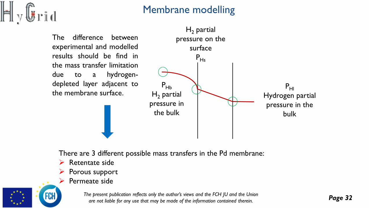
There are 3 different possible mass transfers in the Pd membrane:
➢ Retentate side
➢ Porous support
➢ Permeate side
The difference between
experimental and modelled
results should be find in
the mass transfer limitation
due to a hydrogen-
depleted layer adjacent to
the membrane surface.
Membrane modelling
Page 33The present publication reflects only the author’s views and the FCH JU and the Union
are not liable for any use that may be made of the information contained therein.
0
10000
20000
30000
40000
50000
60000
0.00 0.01 0.02 0.03 0.04 0.05 0.06
Pre
ssure
[P
a]
Lenght [m]
retentate pressure = 5 bar
retentate pressure=4 bar
retentate pressure = 3.5
The pressure on the surface is
remarkably different from the
retentate partial pressure.
0
50
100
150
200
250
0 1 2 3 4 5
Hyd
rog
en f
lux [m
l/m
in]
total pressure difference [bar]
experimentalresult
modeling withmass transferlimitation
modeling nomass transfer
𝐽𝐻 =𝑘𝐻 ∗
𝑃𝐻𝑏 − 𝑃𝐻𝑠𝑅𝑇
1 − (0.5 ∗ (𝑃𝐻𝑏 − 𝑃𝐻𝑠)/𝑃𝑇𝑠
𝑑𝐹𝐻𝑠
𝑑𝑧= −2 ∗ π ∗ 𝑅 ∗ 𝑄𝐻 ∗ (𝑃
𝐻𝑏
𝑛 − 𝑃𝐻𝑙
𝑛)
Surface partial pressure
Retentate partial pressure
𝐽𝐻
=𝑘𝐻 ∗
𝑃𝐻𝑏 − 𝑃𝐻𝑠𝑅𝑇
1 − (0.5 ∗ (𝑃𝐻𝑏 − 𝑃𝐻𝑠)/𝑃𝑇𝑠− 𝑄𝐻
∗ 𝑃𝐻𝑏
𝑛 − 𝑃𝐻𝑙
𝑛 = 0
Membrane modelling
Page 34The present publication reflects only the author’s views and the FCH JU and the Union
are not liable for any use that may be made of the information contained therein.
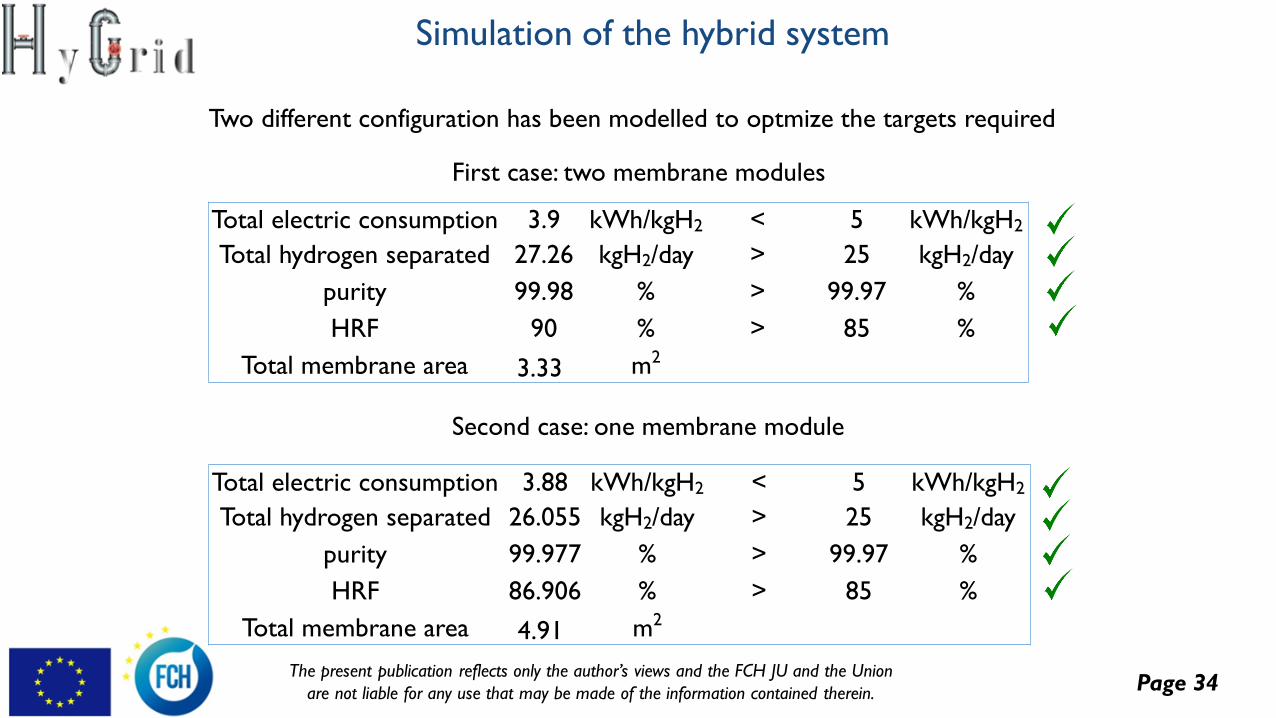
Total electric consumption 3.9 kWh/kgH2 < 5 kWh/kgH2
Total hydrogen separated 27.26 kgH2/day > 25 kgH2/day
purity 99.98 % > 99.97 %
HRF 90 % > 85 %
Total membrane area 3.33 m2
Total electric consumption 3.88 kWh/kgH2 < 5 kWh/kgH2
Total hydrogen separated 26.055 kgH2/day > 25 kgH2/day
purity 99.977 % > 99.97 %
HRF 86.906 % > 85 %
Total membrane area 4.91 m2
Two different configuration has been modelled to optmize the targets required
First case: two membrane modules
Second case: one membrane module
Simulation of the hybrid system
Page 35The present publication reflects only the author’s views and the FCH JU and the Union
are not liable for any use that may be made of the information contained therein.
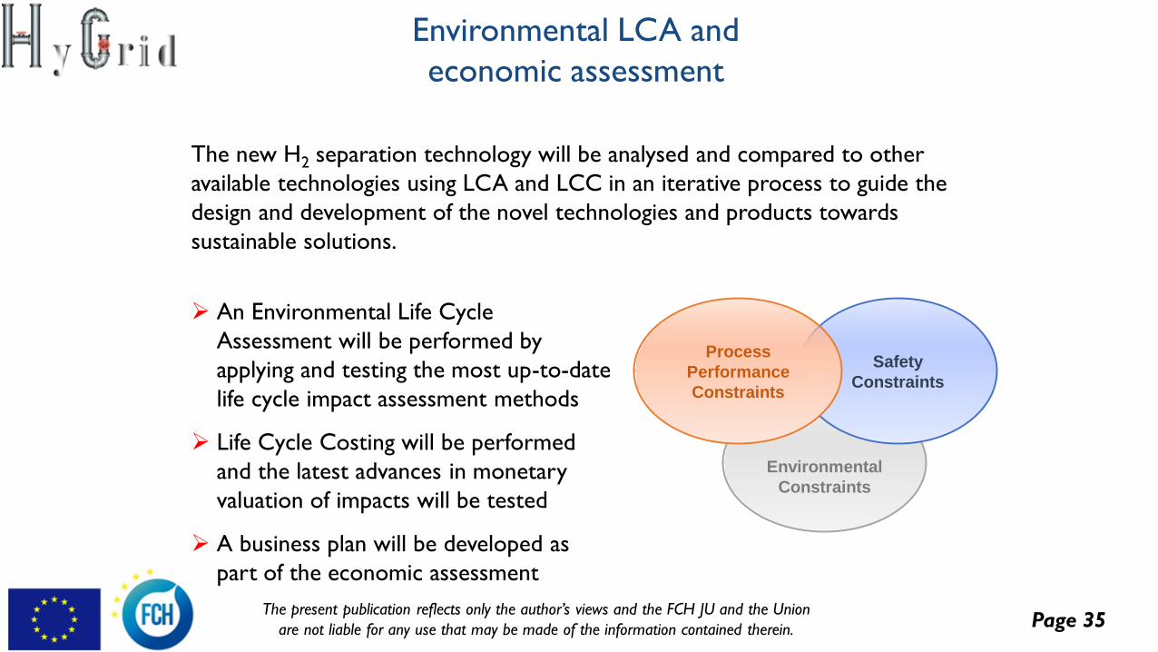
Environmental LCA and
economic assessment
The new H2 separation technology will be analysed and compared to other
available technologies using LCA and LCC in an iterative process to guide the
design and development of the novel technologies and products towards
sustainable solutions.
Environmental
Constraints
Safety
Constraints
Process
Performance
Constraints
➢ An Environmental Life Cycle
Assessment will be performed by
applying and testing the most up-to-date
life cycle impact assessment methods
➢ Life Cycle Costing will be performed
and the latest advances in monetary
valuation of impacts will be tested
➢ A business plan will be developed as
part of the economic assessment
Page 36The present publication reflects only the author’s views and the FCH JU and the Union
are not liable for any use that may be made of the information contained therein.
Overall, the main questions analysed during the goal and scope development include:
➢ What is the aim of the study?
➢ What is the function of the analysed system?
➢ What systems exactly are going to be analysed?
➢ What reference system/ technology will we compare our system against?
➢ What are the system boundaries of the analysed product?
➢ What environmental indicators will be calculated?
➢ What is the data availability for the study?
Goal and scope definition
Page 37The present publication reflects only the author’s views and the FCH JU and the Union
are not liable for any use that may be made of the information contained therein.
➢ Functional unit:
“The recovery from an average European natural gas grid of 1 kg of hydrogen with a purity of at least 99.97%.”
➢ Reference technology (to compare with the HyGrid system):
pressure swing adsorption (PSA)
Main outcomes of goal and scope
definition
Page 38The present publication reflects only the author’s views and the FCH JU and the Union
are not liable for any use that may be made of the information contained therein.
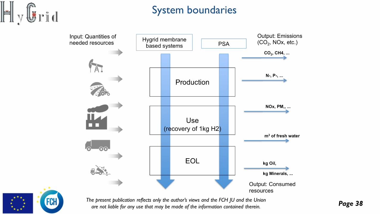
System boundaries
Page 39The present publication reflects only the author’s views and the FCH JU and the Union
are not liable for any use that may be made of the information contained therein.
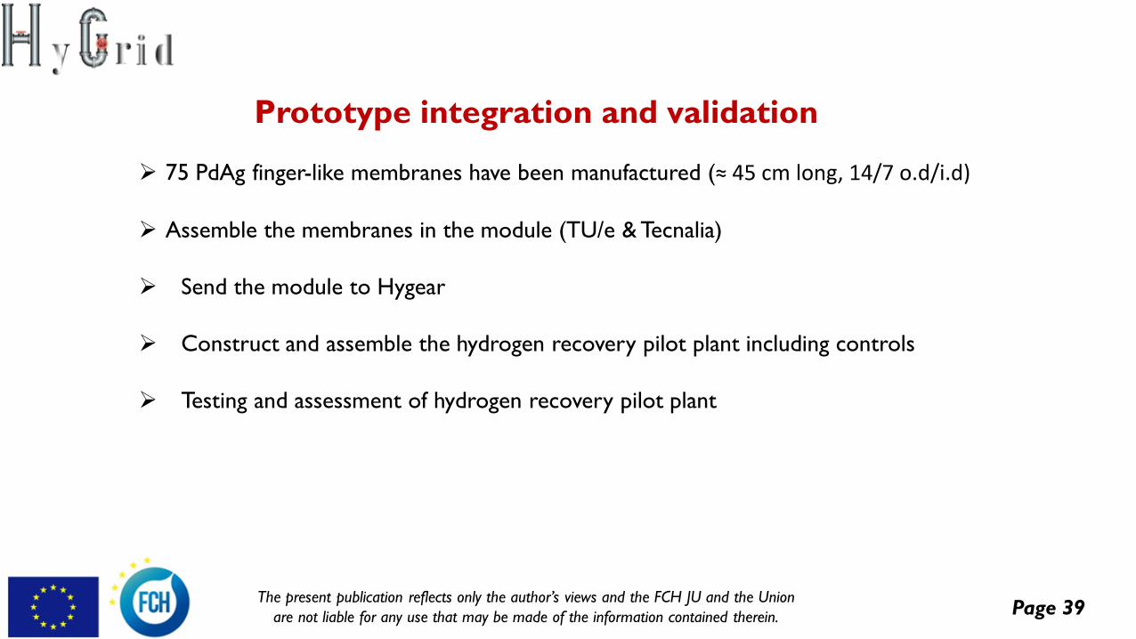
➢ 75 PdAg finger-like membranes have been manufactured (≈ 45 cm long, 14/7 o.d/i.d)
➢ Assemble the membranes in the module (TU/e & Tecnalia)
➢ Send the module to Hygear
➢ Construct and assemble the hydrogen recovery pilot plant including controls
➢ Testing and assessment of hydrogen recovery pilot plant
Prototype integration and validation
Page 40The present publication reflects only the author’s views and the FCH JU and the Union
are not liable for any use that may be made of the information contained therein.
Flexible Hybrid separation system for
H2 recovery from NG Grids
HyGrid
This project has received funding from the Fuel Cells and Hydrogen 2 Joint Undertaking under grantagreement No 700355. This Joint Undertaking receives support from the European Union’s Horizon 2020
research and innovation programme and Hydrogen Europe and N.ERGHY


![SMASH: Structured Matrix Approximation by Separation and ...yxi26/PDF/smash.pdf · The resulting hierarchical rank structured matrices [3,4,5,6], culminated in H2 matrices[7,6], provide](https://img.pdfslide.us/doc/110x75/5ed837c50fa3e705ec0e0e15/smash-structured-matrix-approximation-by-separation-and-yxi26pdfsmashpdf.jpg)