Embed Size (px)
Citation preview
MA4000D
ENGLISH
SVENSKA
User's manualBruksanvisning
� FLEXIBLE CURRENT METER
� STRÖMTÅNG MED FLEXIBEL SPOLE

2
WARNING, risk of DANGER! The operator must refer to these instructions whenever this danger symbol appears.
Equipment protected by double insulation.
Must not be applied to or removed from bare conductors at dangerous voltages. Type B cur‑rent sensor as per IEC 61010‑2‑032.
Battery.
The CE marking indicates conformity with European directives, in particular LVD and EMC.
The rubbish bin with a line through it indicates that, in the European Union, the product must undergo selective disposal in compliance with Directive WEEE 2002/96/EC. This equipment must not be treated as household waste.
Definition of measurement categories: � Measurement category IV corresponds to measurements taken at the source of low‑voltage installations.
� Measurement category III corresponds to measurements on building installations.
� Measurement category II corresponds to measurements taken on circuits directly connected to low‑voltage installations.
PRECAUTIONS FOR USE
This instrument is protected against voltages of not more than 1000V with respect to ground in measurement category III or 600V in CAT IV between the sensor and the conductor of which it measures the current.
The protection provided by the instrument may be impaired if the instrument is used other than as specified by the manufacturer.
� Do not exceed the rated maximum voltage and current or the measurement category.
Thank you for purchasing a DigiFLEX MA4000D current meter with flexible sensor. For best results from your instrument:
� read this user’s manual carefully, � comply with the precautions for use.
English ................................................. 2Svenska ............................................... 6

3
� Observe the conditions of use, namely the temperature, the relative humidity, the altitude, the level of pollution, and the place.
� Before each use, check the integrity of the insulation on the coil, the cords and the housing. Do not use the instrument if it is open, damaged, or poorly reassembled, or its accessories if they appear damaged.
� The sensor must not be applied to or removed from uninsulated conductors at dangerous voltages.
� Use personal protection equipment systematically.
� All troubleshooting and metrological checks must be per‑formed by competent and accredited personnel.
CONTENTS
1. PRESENTATION ...........................................................42. CURRENT MEASUREMENT .......................................6
2.1. Measurement principle ...................................62.2. Use ...................................................................6
3. CHARACTERISTICS ....................................................93.1. Reference conditions ......................................93.2. Electrical characteristics .................................93.3. Variations in range of use .............................103.4. Typical frequency response curves ..............103.5. Power supply .................................................113.8. Environmental conditions .............................113.7. Characteristics of construction ....................123.8. Compliance with international standards ....123.9. Electromagnetic compatibility ......................12
4. MAINTENANCE ..........................................................134.1. Cleaning .........................................................134.2. Replacement of the batteries .......................134.3. Metrological check ........................................134.4. Repair ............................................................13
5. WARRANTY ................................................................146. TO ORDER ..................................................................14
6.1. Accessories ...................................................146.2. Replacement parts ........................................14

4
1. PRESENTATION
The DigiFLEX is used for RMS measurements of current, from 200 mA to 4000 A.
The sensor takes the form of a flexible coil 35 cm long, connected by a shielded cord to a small housing containing the signal processing electronics, supplied by a battery.
The flexibility of the sensors makes it easier to wrap them round the conductor to be measured, whatever its type (cable, bar, strand, etc.) and its accessibility. The design of the snap‑action coil opening and closing device allows it to be handled while wearing protective gloves.
MA 4000DAC RMSCURRENT METER
MAX (>2s)
HOLD
4000 A
600V CAT IV 1000V CAT III
P MAXHOLD
A
Flexible sensor.
Sensor opening device.
Shielded cord.
LCD display unit.
Electronics housing.
HOLD key.
ON/OFF key.

5
On the back of the electronics housing is a notch for the attachment of a belt clip (optional).
The multi‑function belt clip can be used: � to carry the electronic housing on your belt,
� to attach it to a meta l su r face using the built‑in magnet,
� to hook it to a door or the edge of a table.

6
� Open it, then place it round the conductor through which the current to be measured flows (only one conductor in the sensor).
� Close the coil.
2. CURRENT MEASUREMENT
2.1. MEASUREMENT PRINCIPLE
The flexible sensor is based on the Rogowski coil.
It combines: � very good linearity with no saturation effect (and so no heating);
� light weight (no magnetic circuit).
2.2. USE
2.2.1. CONNECTION
First of all, use the appropriate means of protection.
� Press the yellow opening device to open the flexible coil.
In order to optimize measurement quality, it is best to centre the conductor in the coil and to make the shape of the coil as nearly circular as possible.
� Press the key to switch the device on. The display unit lights.
2.2.2. MEASUREMENT
Read the measurement on the display unit. The current is given in Arms.
A
7
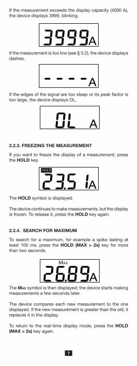
If the measurement exceeds the display capacity (4000 A), the device displays 3999, blinking.
HOLD
A
MAX
A
A
A
If the measurement is too low (see § 3.2), the device displays dashes.
If the edges of the signal are too steep or its peak factor is too large, the device displays OL.
2.2.3. FREEZING THE MEASUREMENT
If you want to freeze the display of a measurement, press the HOLD key.
The Max symbol is then displayed; the device starts making measurements a few seconds later.
The device compares each new measurement to the one displayed. If the new measurement is greater than the old, it replaces it in the display.
To return to the real‑time display mode, press the HOLD (MAX > 2s) key again.
A
The HOLD symbol is displayed.
The device continues to make measurements, but the display is frozen. To release it, press the HOLD key again.
2.2.4. SEARCH FOR MAXIMUM
To search for a maximum, for example a spike lasting at least 100 ms, press the HOLD (MAX > 2s) key for more than two seconds.

8
2.2.5. DE-ACTIVATION OF AUTOMATIC SWITCHING OFF
In order to save the batteries, the device switches itself off automatically at the end of 10 minutes if the user has not pressed a key (unless the MAX function is active).
It is possible to deactivate automatic switching off. To do
this, when you switch the device on, press the and HOLD keys simultaneously. The P symbol (lit steadily) is then dis‑played.
A
P
To reactivate automatic switching off, switch the device off, then back on.
2.2.6. BATTERIES LOW
When the battery voltage drops and the remaining battery life of the device is only about one hour, the symbol blinks on the display unit.
When the battery voltage is too low to guarantee the accu‑racy of the measurements, the symbol lights steadily. The batteries must then be replaced (see § 4.2).
2.2.7. DISCONNECTING
� Switch the device off by pressing the key.
� Press the yellow opening device to open the flexible core.
� Remove the flexible core from the conductor.

9
3. CHARACTERISTICS
3.1. REFERENCE CONDITIONS
Quantity of influence Reference values
Temperature 23 ± 3°C
Relative humidity 45 to 75% RH
Frequency of the signal measured 40 to 65 Hz
Peak factor of the signal measured √2
Conductor diameter ≤ 5 mm
Battery voltage 2.8 ‑ 3.2 V
External electric field none
External DC magnetic field (earth field)
<40 A/m
External AC magnetic field none
Position of the conductorcentred in the
measurement coil
Shape of the measurement coil nearly circular
3.2. ELECTRICAL CHARACTERISTICS
Display range (A) 40 400 4000
Specified measure‑ment range (A)
0.20 ‑ 39.99
40.0 ‑ 399.9
400 ‑ 3999
Resolution 10 mA 100 mA 1 A
Intrinsic uncertainty±(2%
+ 10 ct)±(1.5% + 2 ct)
±(1.5% + 2 ct)
In MAX mode:
Display range (A) 40 400 4000
Specified measure‑ment range (A)
1.00 ‑ 39.99
40.0 ‑ 399.9
400 ‑ 3999
Resolution 10 mA 100 mA 1 A
Typical error±(2%
+ 10 ct)±(1.5% + 2 ct)
±(1.5% + 2 ct)

10
3.3. VARIATIONS IN RANGE OF USE
Quantity of influence Range of influenceError on the measurement
Typical Maximum
Battery voltage 1.8 to 2 V < 1 ct ±(2% + 1 ct)
Temperature 0 to 50 °C ± 0.25 % / 10 °C ±( 0.5 % / 10 °C + 2 ct)
Relative humidity 10 to 90% RH 0.2% ± (0.3 % + 2 ct)
Frequency response
10 to 20 Hz20 Hz to 30 Hz30 Hz to 400 Hz400 to 1000 Hz1000 to 3000 Hz
See § 3.4
± (5 % + 1 ct)± (1 % + 1 ct)
± (0.5 % + 1 ct)± (6 % + 1 ct)‑ 3 dB typical
Position of the conductor in the sensor (f<400 Hz)
Any position on the interior perimeter of the sensor
± 0.5 % ± (1.5 % ± 1 ct)
A d j a c e n t c o n d u c t o r carrying alternating current
Conductor touching the ex‑terior perimeter of the sensor
Away from opening: 55 dBAt opening: 55 dB
Away from opening: ≥ 45 dBAt opening: ≥ 45 dB
Peak factor1.4 to 3.5
limited to 6000 Apeak
at 16.66 Hz : ± (2 % + 1 ct)at 50 Hz : ± (0.5 % + 1 ct)at 440 Hz : ± (30 % + 1 ct)
± (6 % + 1 ct)± (3 % + 1 ct)
‑
Serial mode rejection ratio in AC
0 to 400 Adc < 1 ct ≥ 50 dB
Common mode rejection, 50/60 Hz
0 to 600 Vrms < 1 ct ≥ 60 dB
Influence of a 50/60 Hz ex‑ternal magnetic field
0 to 400 A/mHousing: 43 dBSensor: 50 dB
Housing: ≥ 30 dBSensor: ≥ 40 dB
3.4. TYPICAL FREQUENCY RESPONSE CURVES
at 39 Aac
-50 %
-40 %
-30 %
-20 %
-10 %
0 %
10 %
10 Hz 100 Hz 1000 Hz 10000 Hz

11
3.3. VARIATIONS IN RANGE OF USE
Quantity of influence Range of influenceError on the measurement
Typical Maximum
Battery voltage 1.8 to 2 V < 1 ct ±(2% + 1 ct)
Temperature 0 to 50 °C ± 0.25 % / 10 °C ±( 0.5 % / 10 °C + 2 ct)
Relative humidity 10 to 90% RH 0.2% ± (0.3 % + 2 ct)
Frequency response
10 to 20 Hz20 Hz to 30 Hz
30 Hz to 400 Hz400 to 1000 Hz1000 to 3000 Hz
See § 3.4
± (5 % + 1 ct)± (1 % + 1 ct)
± (0.5 % + 1 ct)± (6 % + 1 ct)‑ 3 dB typical
Position of the conductor in the sensor (f<400 Hz)
Any position on the interior perimeter of the sensor
± 0.5 % ± (1.5 % ± 1 ct)
A d j a c e n t c o n d u c t o r carrying alternating current
Conductor touching the ex‑terior perimeter of the sensor
Away from opening: 55 dBAt opening: 55 dB
Away from opening: ≥ 45 dBAt opening: ≥ 45 dB
Peak factor1.4 to 3.5
limited to 6000 Apeak
at 16.66 Hz : ± (2 % + 1 ct)at 50 Hz : ± (0.5 % + 1 ct)at 440 Hz : ± (30 % + 1 ct)
± (6 % + 1 ct)± (3 % + 1 ct)
‑
Serial mode rejection ratio in AC
0 to 400 Adc < 1 ct ≥ 50 dB
Common mode rejection, 50/60 Hz
0 to 600 Vrms < 1 ct ≥ 60 dB
Influence of a 50/60 Hz ex‑ternal magnetic field
0 to 400 A/mHousing: 43 dBSensor: 50 dB
Housing: ≥ 30 dBSensor: ≥ 40 dB
3.5. POWER SUPPLY
The device can be powered: � either by two 1.5 V R03 (AAA) alkaline batteries, � or by two NiMH storage batteries of the same size.
The nominal operating voltage is between 1.8 and 3.2 V.The battery life in continuous operation is:
� 70 hours with super‑alkaline batteries, � 50 hours with NiMH storage batteries having a capacity of 1200 mAh.
The low battery condition is reported by the blinking symbol on the display unit. When it is lit steadily, the batter‑ies must be replaced (see § 4.2).
3.8. ENVIRONMENTAL CONDITIONS
The instrument must be used in the following conditions: � Temperature in use: 0°C to +50°C � Storage temperature: ‑20°C to +70°C
(without batteries) � Relative humidity in use: 80% RH to 50°C � Relative humidity in storage: 90% RH (up to 45°C)
The sensor can withstand a temperature of 90°C.

12
For indoor use.Level of pollution: 2.Altitude: <2000 m.
3.7. CHARACTERISTICS OF CONSTRUCTION
Overall dimensions � Housing: 100 x 60 x 20 mm � Connecting cable: 0.70 m � Sensor
� Length (mm) 350 mm � Clamping diameter 100 mm
Mass of the device: approximately 130 g.
Index of protection: IP 40 per IEC 60529 IK 04 per IEC 50102
Afterflame time: V0 (per UL 94)
The flexible coil is resistant to oils and aliphatic hydrocarbons.
3.8. COMPLIANCE WITH INTERNATIONAL STANDARDS
Electrical safety per IEC 61010‑2‑032 for type B sensors. Rated voltage 600 V with respect to earth in category IV.
Double insulation:
3.9. ELECTROMAGNETIC COMPATIBILITY
Emissions and immunity in an industrial setting compliant with IEC 61326‑1 for portable devices.

13
4. MAINTENANCE
Any unauthorized repair or replacement of a part by an “equivalent” may gravely impair safety.
4.1. CLEANING
Disconnect everything connected to the instrument and switch it off.
Use a soft cloth, dampened with soapy water. Rinse with a damp cloth and dry rapidly with a dry cloth or forced air. Do not use alcohol, solvents, or hydrocarbons.
Make sure that no foreign body interferes with the operation of the snap device of the sensor.
4.2. REPLACEMENT OF THE BATTERIES
The battery must be replaced when the green indicator flashes or remains off when the instrument is switched on.
� Disconnect everything connected to the instrument and and switch it off.
� Use a screwdriver to unscrew the two closing screws of the housing.
� Replace the old battery with a new battery (1.5 V R03 or AAA super‑alkaline batteries).
� Close the housing; make sure that it is completely and correctly closed.
� Screw both screws back in.
Spent batteries must not be treated as ordinary household waste. Take them to the appropriate recycling collection point.
4.3. METROLOGICAL CHECK
Like all measuring or testing devices, regular instru-ment verification is necessary.
This instrument should be checked at least once a year. For checks and calibrations, contact one of our accredited metrology laboratories (information and contact details available on request), at our Chauvin Arnoux subsidiary or the branch in your country.
4.4. REPAIR
For all repairs before or after expiry of warranty, please return the device to your distributor.

14
5. WARRANTY
Except as otherwise stated, our warranty is valid for twelve months starting from the date on which the equipment was sold. Extract from our General Conditions of Sale, provided on request.
The warranty does not apply in the following cases: � inappropriate use of the equipment or use with incompat‑ible equipment;
� modifications made to the equipment without the explicit permission of the manufacturer’s technical staff;
� work done on the device by a person not approved by the manufacturer;
� adaptation to a particular application not anticipated in the definition of the equipment or not indicated in the user’s manual;
� damage caused by shocks, falls, or floods.
6. TO ORDER
DigiFLEX MA4000D-350 ............................... P01120577ZDelivered in a blister pack with:
� two 1,5 V piles alkaline battery (AAA), � one Velcro fastener � one user’s manual in 5 languages, � one certificate of verification.
6.1. ACCESSORIES
Carrying bag 120x200x60 .............................. P01298074Multi‑function belt clip .................................. P01102100Z
6.2. REPLACEMENT PARTS
Set of 5 Velcro fasteners ............................... P01102113

15
16
VARNING, risk för FARA! Användaren måste noggrant läsa bruksanvisningen när denna symbol visas.
Instrumentet är skyddat med dubbel isolering.
Får inte användas på eller tas bort från oisolerade eller bara ledare med farliga spänningar. Typ B strömspole enligt IEC 61010‑2‑032.
Batteri.
CE‑märkningen indikerar överensstämmelse med EU‑direktiv, särskilt LVD och EMC.
Soptunnan med en kryssmarkering indikerar inom Europeiska unionen, att produkten måste genomgå selektiv avfallshantering enlighet med direktiv WEEE 2002/96/EC. Den här utrustningen får inte behandlas som hushållsavfall.
Definition av mätkategorier: � Mätkategori IV motsvarar mätningar på matning till låg‑spänningsinstallationer.
� Mätkategori III motsvarar mätningar på fastighetsinstal‑lationer.
� Mätkategori II motsvarar mätningar som utförs på kretsar direkt kopplade till lågspänningsinstallationer.
FÖRSIKTIGHETSÅTGÄRDER VID ANVÄNDNING
Instrumentet är skyddat mot spänningar upp till 1 000V i förhållande till jord i mätkategori III eller 600V i CAT IV mellan spolen och ledaren som strömmen mäts i.
Instrumentets inbyggda skydd kan försämras om instru‑mentet används på annat sätt än som anges av tillverkaren.
� Överskrid inte den maximalt specificerade spänningen och strömmen eller mätkategorin.
Tack för att du köpt en DigiFLEX MA4000D strömtång med flexibel spole. För att uppnå bästa resultat med ditt instrument:
� Läs den här bruksanvisningen noggrant. � Observera användarinstruktionerna.
SVENSKA

17
� Observera villkoren för användning, nämligen temperaturen, den relativa fuktigheten, höjden, graden av förorening, och platsen.
� Innan varje användning, Kontrollera spolens isolation, kablarna och höljet. Använd inte instrumentet om det är öppet, skadat, eller dåligt hopsatt, eller om dess tillbehör verkar skadade.
� Spolen får inte användas på eller tas bort från oisolerade eller bara ledare med farliga spänningar.
� Använd alltid nödvändig personlig skyddsutrustning.
� All felsökning och kalibrering måste utföras av kompetent och ackrediterad personal.
INNEHÅLLSFÖRTECKNING
1. PRESENTATION .........................................................182. STRÖMMÄTNING ......................................................20
2.1. Mätprincip .....................................................202.2. Användning ....................................................20
3. TEKNISKA DATA ........................................................233.1. Referensvillkor ...............................................233.2. Elektriska specifikationer ..............................233.3. Storheter som påverkar mätonoggrannheten .243.4. Typiska frekvensresponskurvor ....................243.5. Strömförsörjning............................................253.8. Miljövillkor ......................................................253.7. Mekaniska egenskaper .................................263.8. Överensstämmelse med internationella normer ..........................................................263.9. Elektromagnetisk kompatibilitet ...................26
4. UNDERHÅLL ..............................................................274.1. Rengöring ......................................................274.2. Byte av batterierna ........................................274.3. Kalibrering .....................................................274.4. Reparation .....................................................27
5. GARANTI ....................................................................286. ATT BESTÄLLA ..........................................................28
6.1. Tillbehör .........................................................286.2. Reservdelar ...................................................28

18
MA 4000DAC RMSCURRENT METER
MAX (>2s)
HOLD
4000 A
600V CAT IV 1000V CAT III
P MAXHOLD
A
1. PRESENTATION
DigiFLEX används för TRMS mätningar av ström, från 200 mA till 4000 A.
Sensorn har formen av en flexibel spole 35 cm lång, anslu‑ten med en skärmad kabel till ett litet hölje som innehåller elektronik för signalbehandling, strömförsörjd med ett batteri.
Spolens flexibilitet gör det lätt att omsluta den runt ledaren som skall mätas, oavsett typ (kabel, skena etc.) och dess tillgänglighet. Utförandet med snäppteknik för öppning och stängning av spolen gör att den kan hanteras även med skyddshandskar.
Flexibel spole.
Spolöppning sanordning.
Skärmad kabel.
LCD displayenhet.
HOLD tangent.
ON/OFF tangent.
Elektronikhölje.

19
På baksidan av elektronikhöljet finns en skåra för att fästa en bältesklämma (option).
Multi‑funktions bältesklämman kan användas till: � Att bära elektronikhöljet på bältet,
� Att fästa elektro‑nikhöljet på en metal lyta med den inbyggda magneten,
� Att fästa elektro‑nikhöljet på en dörr eller på kan‑ten av ett bord.

20
2. STRÖMMÄTNING
2.1. MÄTPRINCIP
Den flexibla spolen är baserad på Rogowski spolen.
Den kombinerar: � mycket god linjäritet utan mättnadseffekt (och ingen värme);
� låg vikt (ingen magnetisk krets).
2.2. ANVÄNDNING
2.2.1. ANSLUTNING
Först av allt, skydda dig på lämpligt sätt.
� Tryck på den gula öppningsanordningen för att öppna den flexibla spolen.
� Öppna den och placera den runt den ledare som skall mätas (endast en ledare i spolen).
� Stäng spolen.
För att optimerad mätkvaliteten, är det bäst att centrera ledaren i spolen och göra formen på spolen så nära cir‑kulär som möjligt.
� Tryck på tangenten för att slå på strömtången. Displayenheten tänds.
2.2.2. MÄTNING
Läs mätresultatet på displayenheten. Strömmen anges i Arms.
A
21
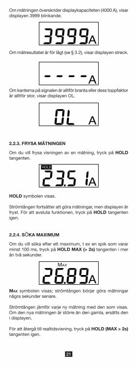
2.2.3. FRYSA MÄTNINGEN
Om du vill frysa visningen av en mätning, tryck på HOLD tangenten.
HOLD
AHOLD symbolen visas.
Strömtången fortsätter att göra mätningar, men displayen är fryst. För att avsluta funktionen, tryck på HOLD tangenten igen.
2.2.4. SÖKA MAXIMUM
Om du vill söka efter ett maximum, t ex en spik som varar minst 100 ms, tryck på HOLD MAX (> 2s) tangenten i mer än två sekunder.
MAX
AMax symbolen visas; strömtången börjar göra mätningar några sekunder senare.
Strömtången jämför varje ny mätning med den som visas. Om den nya mätningen är större än den gamla, ersätts den i displayen.
För att återgå till realtidsvisning, tryck på HOLD (MAX > 2s) tangenten igen.
Om mätningen överskrider displaykapaciteten (4000 A), visar displayen 3999 blinkande.
AOm mätresultatet är för lågt (se § 3.2), visar displayen streck.
AOm kanterna på signalen är alltför branta eller dess toppfaktor är alltför stor, visar displayen OL.
A

22
A
P
För att återaktivera automatisk avstängning, stänga av strömtången och slå sedan den igen.
2.2.6. LÅG BATTERINIVÅ
När batterispänningen sjunker och den återstående batteri‑tiden endast är ca en timme, blinkar symbolen på displayenheten.
När batterispänningen är för låg för att garantera noggrann‑heten i mätningarna, lyser symbolen stadigt. Då måste batterierna bytas (se § 4.2).
2.2.7. KOPPLA BORT
� Stäng av strömtången genom att trycka på knappen.
� Tryck på den gula öppningsanordningen för att öppna den flexibla spolen.
� Ta bort den flexibla spolen från ledaren.
2.2.5. INAKTIVERING AV AUTOMATISK AVSTÄNGNING
För att spara batterierna, stängs enheten av automatiskt efter 10 minuter om användaren inte har tryckt på någon tangent (såvida MAX funktionen inte är aktiv).
Det är möjligt att inaktivera automatisk avstängning. För att
göra detta, tryck på och HOLD tangenterna samtidigt som du slår på strömtången. P symbolen (lyser stadigt) visas.

23
3. TEKNISKA DATA
3.1. REFERENSVILLKOR
Parameter Referensvärden
Temperatur 23 ± 3 °C
Relativ fuktighet 45 till 75 % HR
Frekvensområde för mätsignalen 45 till 65 Hz
Peak faktor för mätsignalen √2
Ledardiameter ≤ 5 mm
Batterispänning 2,8 ‑ 3,2 V
Externt elektriskt fält Inget
Externt DC magnetfält (jord fält) < 40 A/m
Externt AC magnetfält Inget
Ledarens position Centrerad i mätspolen
Mätspolens form Nära cirkulär
3.2. ELEKTRISKA SPECIFIKATIONER
Displayområde (A) 40 400 4000
Specificerat mätom‑råde (A)
0,20 ‑ 39,99
40,0 ‑ 399,9
400 ‑ 3999
Upplösning 10 mA 100 mA 1 A
Inneboende osäkerhet
±(2% + 10 siffra)
±(1,5% + 2 siffra)
±(1,5% + 2 siffra)
I MAX läge:
Displayområde (A) 40 400 4000
Specificerat mätom‑råde (A)
1,00 ‑ 39,99
40,0 ‑ 399,9
400 ‑ 3999
Upplösning 10 mA 100 mA 1 A
Typiskt fel±(2%
+ 10 siffra)±(1,5%
+ 2 siffra)±(1,5%
+ 2 siffra)

24
3.3. STORHETER SOM PÅVERKAR MÄTO- NOGGRANNHETEN
Typ av inflytande OmrådeFel i mätningen
Typiskt Max
Batterispänning 1,8 till 3,2 V < 1 siffra ±(0,2% + 1 siffra)
Temperatur 0 till 50 °C ± 0,25 % / 10 °C ± (0,5 % / 10 °C + 2 siffra)
Relativ fuktighet 10 till 90% HR ± 0,2 % ± (0,3 % + 2 siffra)
Frekvens
10 till 20 Hz20 Hz till 30 Hz30 Hz till 400 Hz400 till 1000 Hz1000 till 3000 Hz
Se § 3.4
± (5 % + 1 siffra)± (1 % + 1 siffra)
± (0,5 % + 1 siffra)± (6 % + 1 siffra)
‑ 3 dB typiskt
Ledarens position i spolen(f < 400 Hz)
Varje position i den inre om‑kretsen av spolen
± 0,5 % ± (1,5 % + 1 siffra)
Intilliggande ledare med växelström
Ledare i beröring med den yttre omkretsen av spolen
Inte nära öppning: 33 dBVid öppning: 30 dB
Inte nära öppning: ≥ 28 dBVid öppning: ≥ 25 dB
Peak faktor1,4 till 3,5
Begränsad till 600 A peak
Vid 16,66 Hz : ± (2 % + 1 siffra)Vid 50 Hz : ± (0,5 % + 1 siffra)Vid 440 Hz : ± (30 % + 1 siffra)
± (6 % + 1 siffra)± (3 % + 1 siffra)
‑
S M R R ( S e r i a l M o d e Rejection Ratio) i AC
0 till 400 Adc < 1 siffra ≥ 50 dB
C M R ( C o m m o n M o d e Rejection), 50/60 Hz
0 till 600 Vrms < 1 siffra ≥ 60 dB
Inflytande av ett 50/60 Hz externt magnetfält
0 till 400 A/mHölje: 43 dBSpole: 50 dB
Hölje: ≥ 30 dBSpole: ≥ 40 dB
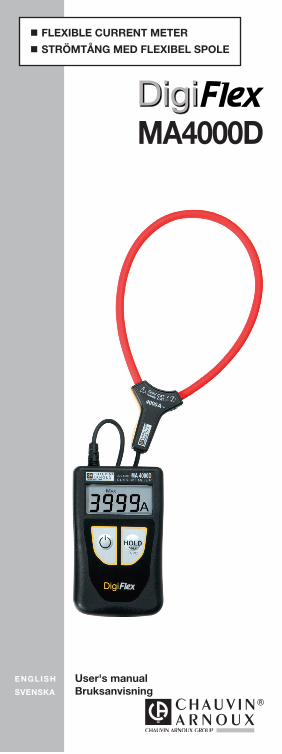
3.4. TYPISKA FREKVENSRESPONSKURVOR
vid 39 Aac
-50 %
-40 %
-30 %
-20 %
-10 %
0 %
10 %
10 Hz 100 Hz 1000 Hz 10000 Hz

25
3.3. STORHETER SOM PÅVERKAR MÄTO- NOGGRANNHETEN
Typ av inflytande OmrådeFel i mätningen
Typiskt Max
Batterispänning 1,8 till 3,2 V < 1 siffra ±(0,2% + 1 siffra)
Temperatur 0 till 50 °C ± 0,25 % / 10 °C ± (0,5 % / 10 °C + 2 siffra)
Relativ fuktighet 10 till 90% HR ± 0,2 % ± (0,3 % + 2 siffra)
Frekvens
10 till 20 Hz20 Hz till 30 Hz30 Hz till 400 Hz400 till 1000 Hz1000 till 3000 Hz
Se § 3.4
± (5 % + 1 siffra)± (1 % + 1 siffra)
± (0,5 % + 1 siffra)± (6 % + 1 siffra)
‑ 3 dB typiskt
Ledarens position i spolen(f < 400 Hz)
Varje position i den inre om‑kretsen av spolen
± 0,5 % ± (1,5 % + 1 siffra)
Intilliggande ledare med växelström
Ledare i beröring med den yttre omkretsen av spolen
Inte nära öppning: 33 dBVid öppning: 30 dB
Inte nära öppning: ≥ 28 dBVid öppning: ≥ 25 dB
Peak faktor1,4 till 3,5
Begränsad till 600 A peak
Vid 16,66 Hz : ± (2 % + 1 siffra)Vid 50 Hz : ± (0,5 % + 1 siffra)Vid 440 Hz : ± (30 % + 1 siffra)
± (6 % + 1 siffra)± (3 % + 1 siffra)
‑
S M R R ( S e r i a l M o d e Rejection Ratio) i AC
0 till 400 Adc < 1 siffra ≥ 50 dB
C M R ( C o m m o n M o d e Rejection), 50/60 Hz
0 till 600 Vrms < 1 siffra ≥ 60 dB
Inflytande av ett 50/60 Hz externt magnetfält
0 till 400 A/mHölje: 43 dBSpole: 50 dB
Hölje: ≥ 30 dBSpole: ≥ 40 dB
3.5. STRÖMFÖRSÖRJNING
Strömtången kan drivas med: � antingen med två 1,5 V R03 (AAA) alkaliska batterier, � eller med två NiMH batterier av samma storlek.
Den nominella driftspänningen ligger mellan 1,8 och 3,2 V.Batteriets livslängd vid kontinuerlig drift är:
� 70 timmar med super‑alkaliska batterier, � 50 timmar med NiMH batterier som har en kapacitet på 1200 mAh.
För låg batterikapacitet visas med den blinkande symbolen på displayenheten. När symbolen lyser stadigt måste batterierna bytas (se § 4.2).
3.8. MILJÖVILLKOR
Instrumentet måste användas under följande villkor: � Temperatur vid användning: 0°C to +50°C � Lagringstemperatur: ‑20°C to +70°C
(utan batterier) � Relativ fuktighet vid användning: 80 % RH to 50°C � Relativ fuktighet vid lagring: 90 % RH (up to 45°C)
Spolen kan motstå en temperatur av 90°C.

26
För inomhusbruk.Föroreningsgrad: 2.Höjd: <2 000 m.
3.7. MEKANISKA EGENSKAPER
Yttermått: � Hölje: 100 x 60 x 20 mm � Anslutningskabel: 0,70 m � Spole
� Längd (mm) 350 mm � Öppningsdiameter 100 mm
Vikt: Ca 130 g.
Skyddsklass: IP 40 enligt IEC 60529 IK 04 enligt IEC 50102
Efterflammningstid: V0 (enligt UL 94)
Den flexibla spolen är resistent mot oljor och kolväten.
3.8. ÖVERENSSTÄMMELSE MED INTERNA-TIONELLA NORMER
Elektrisk säkerhet med IEC 61010‑2‑032 för typ B givare. Märkspänning 600 V i förhållande till jord i kategori IV.
Dubbel isolering:
3.9. ELEKTROMAGNETISK KOMPATIBILITET
Emission och immunitet i en industriell miljö enligt IEC 61326‑1 för bärbara enheter.

27
4. UNDERHÅLL
All obehörig reparation eller utbyte av en del mot en ”likvärdig” kan allvarligt försämra säkerheten.
4.1. RENGÖRING
Koppla bort alla anslutningar till instrumentet och stäng av det.
Använd en mjuk trasa fuktad med tvålvatten. Skölj med en fuktig trasa och torka snabbt med en torr trasa eller varmluft. Använd inte alkohol, lösningsmedel eller kolväten.
Se till så att inga främmande föremål stör funktionen hos spolens snäppanordning.
4.2. BYTE AV BATTERIERNA
Batterierna måste bytas ut när den gröna indikatorn blinkar eller förblir släckt när instrumentet slås på.
� Koppla bort alla anslutningar till instrumentet och stäng av. � Använd en skruvmejsel för att skruva loss de två lås‑skruvarna till höljet.
� Byt ut de gamla batterierna mot nya (1,5 V R03 eller AAA super‑alkaliska batterier).
� Stäng höljet, kontrollera att det är fullständigt och kor‑rekt stängt.
� Skruva tillbaka de båda skruvarna igen.
Förbrukade batterier får inte behandlas som vanligt hushållsavfall. Ta dem till lämplig uppsamlingsplats för återvinning.
4.3. KALIBRERING
Som med alla andra mät- och testutrustningar, måste instrumentet kalibreras regelbundet.
Instrument bör kalibreras minst en gång om året. För kontrol‑ler och kalibreringar, kontakta ett ackrediterat företag med kalibreringsservice, eller kontakta:
CA Mätsystem AB, tel 08‑505 268 00, fax 08‑505 268 10Email: info@chauvin‑arnoux.sewww.chauvin‑arnoux.se
4.4. REPARATION
För alla reparationer under eller efter garantins utgång, v.v. returnera instrumentet med felbeskrivning till din distributör eller till CA Mätsystem AB.

28
5. GARANTI
Om inte annat angivits, är vår garanti giltig i tolv månader räknat från den dag då utrustningen levereras. Vi tillämpar IMLs allmänna leveransbestämmelser.Dessa finns att läsa i .pdf format på vår hemsida: www.chauvin‑arnoux.se
Garantin gäller inte i följande fall: � Olämplig användning av instrumentet eller användning med inkompatibla tillbehör;
� Ändringar gjorda på utrustningen utan uttryckligt tillstånd av tillverkarens tekniska personal;
� Ingrepp i utrustningen av personal som inte är godkänd av tillverkaren;
� Efterjusteringar av utrustningen till specifika tillämpningar för vilka utrustningen inte är avsedd eller som inte nämns i manualen;
� Skador orsakade av stötar, fall, eller översvämningar.
6. ATT BESTÄLLA
DigiFLEX MA4000D-350 ............................... P01120577ZLevereras i sin förpackning med:
� Två 1,5 V alkaliska batterier (AAA) � Ett kardborreband � En bruksanvisning på 5 språk � Ett verifieringscertifikat.
6.1. TILLBEHÖR
Transportväska 120x200x60 .......................... P01298074Multi‑funktions bältesklämma ........................ P01102100Z
6.2. RESERVDELAR
Set med 5 kardborreband .............................. P01102113

29

30

31

02 ‑ 2013 Code 693866A01 ‑ Ed. 1
http://www.chauvin-arnoux.com
190, rue Championnet ‑ 75876 PARIS Cedex 18 ‑ FRANCETél. : +33 1 44 85 44 85 ‑ Fax : +33 1 46 27 73 89 ‑
info@chauvin‑arnoux.frExport : Tél. : +33 1 44 85 44 86 ‑ Fax : +33 1 46 27 95 59 ‑
export@chauvin‑arnoux.fr
DEUTSCHLAND - Chauvin Arnoux GmbHStraßburger Str. 34 ‑ 77694 Kehl / RheinTel: (07851) 99 26‑0 ‑ Fax: (07851) 99 26‑60
ESPAÑA - Chauvin Arnoux Ibérica S.A.C/ Roger de Flor, 293 ‑ 1a Planta ‑ 08025 BarcelonaTel: 902 20 22 26 ‑ Fax: 934 59 14 43
ITALIA - Amra SpAVia Sant’Ambrogio, 23/25 ‑ 20050 Macherio (MI)Tel: 039 245 75 45 ‑ Fax: 039 481 561
ÖSTERREICH - Chauvin Arnoux Ges.m.b.HSlamastrasse 29/2/4 ‑ 1230 WienTel: 01 61 61 9 61‑0 ‑ Fax: 01 61 61 9 61‑61
SCANDINAVIA - CA Mätsystem ABBox 4501 ‑ SE 18304 TÄBYTel: +46 8 50 52 68 00 ‑ Fax: +46 8 50 52 68 10
SCHWEIZ - Chauvin Arnoux AGMoosacherstrasse 15 ‑ 8804 AU / ZH Tel: 044 727 75 55 ‑ Fax: 044 727 75 56
UNITED KINGDOM - Chauvin Arnoux LtdUnit 1 Nelson Ct ‑ Flagship Sq ‑ Shaw Cross Business PkDewsbury, West Yorkshire ‑ WF12 7THTel: 01924 460 494 ‑ Fax: 01924 455 328
MIDDLE EAST - Chauvin Arnoux Middle EastP.O. BOX 60‑154 ‑ 1241 2020 JAL EL DIB (Beirut) ‑ LEBANONTel: (01) 890 425 ‑ Fax: (01) 890 424
CHINA - Shanghai Pu-Jiang - Enerdis Instruments Co. Ltd3 F, 3 rd Building ‑ N° 381 Xiang De Road ‑ 200081 SHANGHAITel: +86 21 65 21 51 96 ‑ Fax: +86 21 65 21 61 07
USA - Chauvin Arnoux Inc - d.b.a AEMC Instruments200 Foxborough Blvd. ‑ Foxborough ‑ MA 02035Tel: (508) 698‑2115 ‑ Fax: (508) 698‑2118