Embed Size (px)
Citation preview

Flexible AC Transmission Systems (FACTS)
Parallel compensationComprehensive solutions for safe and reliable grid operation
siemens.com/energy

In grid operation, nothing is as constant as change
Operators of power grids around the world are experi encing continuous change in their industry: For ecological and economic reasons, the energy mix is changing toward an ever larger share of renewable power sources. Their volatility brings fundamental challenges to grid operators and demands different strategies to guarantee stable power supply at all times.
2

New challengesFundamental changes are impacting the power industry. Markets are being deregulated and liberalized, urbanization is continuing around the world, all this accompanied by a constantly growing demand for energy. At the same time, ambitious environmental and CO2 reduction goals call for a more efficient utilization of energy sources. This is reflected in a massive shift in the energy mix toward an increasing share of renewable energy sources, while large thermal power plants are being shut down for environ mental or economic reasons.
For grid operators, these changes mean enormous challenges in their effort to fulfill their core task: keeping the transmission system both stable and reliable while maintaining the safety and security of the power supply at all times, today and into the future. In many cases, building new lines or other major infrastructure is not the first choice for mitigating bottlenecks, because approval processes can take several years and the investments are very high.
Our answersOver the last three decades Siemens has thoroughly analyzed this situation and has come up with an entirely different approach. For utility applications, the solution is rooted in the existing transmission infrastructure, but it uses it more efficiently. Our solutions are also available in a reasonable time frame, and don’t incite public opposition, because they don’t require extensive landscape alterations. Our Flexible AC transmission systems (FACTS) are a powerful set of electric devices that can be very eco nomically integrated at critical nodes in the transmission grid to provide the necessary stability and many other features. For industrial applications, FACTS optimize the utilization of energy and its distribution. For more than 30 years, Siemens has been an innovation leader in FACTS technology.
3

4

While every power grid and every large industrial consumer has specific challenges in terms of power quality, reactive power compensation, and grid stability, our FACTS systems offer customized solutions to these challenges from a single source.
Modular versatilityFlexible AC transmission systems (FACTS) are a family of power transmission solutions that contribute to enhanced grid stability and power quality. Its specialized devices offer both • parallel and• series compensation.
While series compensation is primarily used to increase the power transfer capability on transmission lines, the devices for parallel compensation influence the network voltage at their point of common coupling by actively injecting or absorbing reactive power. Parallel connected synchronous condensers stabilize the network by providing short circuit power and inertia. With these solutions installed in the system, unacceptably high voltage fluctuations and power failures can be prevented, network assets can be optimally utilized, and loadinduced disturbances can be mitigated.
Power electronics – a decisive breakthroughFor decades, reactive power compensation was accomplished by either simple mechanically switched capacitors/ reactors or by power plant generators. However, with these mechanical solutions, response time, control accuracy, and economic impact were not optimal. The evolution of power electronics brought a massive step forward in grid stability and power quality as devices such as Static Var Compensators (SVC) were developed. They use thyristors – very fastacting semiconductor elements – to switch capacitors and control reactors. This permits very rapid and smart control of reactive power and therefore of network voltage. Static synchronous compensator ( STATCOM) devices are a more recent development and serve the same purpose, though they employ a different technical principle. Traditional mechanical devices like the synchronous condenser complete Siemens’ FACTS portfolio.
Comprehensive consulting – the key to successEvery electrical grid is different, and requirements for voltage stability and reactive power flow differ significantly depending on location, energy demand, load flow, and many other factors. As a result, choosing the best or most economical FACTS solution may produce different results. Siemens takes pride in offering all the standard solutions for reactive power compensation built from components supplied by our own factories, and for good reason: It allows us to consult with our clients in a neutral manner.
Grid stability and power quality made to order
5

Technology MSC(DN) / MSR SVC SVC PLUS (STATCOM) Hybrid STATCOM Synchronous CondenserApplication Compensation of predictable load
changesFast dynamic compensation and voltage recovery during faults
Fast dynamic compensation and voltage recovery during faults
Fast dynamic compensation and voltage recovery during faults
Provision of shortcircuit power, inertia, dynamic compensation, and voltage recovery during faults
Switching Limited switching only Unlimited switching Unlimited switching Unlimited switching Continuous operation
V/I characteristic No response Good overvoltage performance Superior undervoltage performance Superior undervoltage performance Good overload capability
Control range Adjustable by MSC and MSR ranges Adjustable by branch ranges Symmetrical output: Adjustable range Unsymmetrical output: Adjustable range Adjustable by generator size
Redundancy No inbuilt redundancy Inbuilt redundancy in thyristor valves Inbuilt redundancy in power modules Inbuilt redundancy in power modules and in thyristor valves
Depending on solution
Harmonics Susceptible to harmonics TCR is source of harmonics – AC filters required
Harmonically selfcompensated – no filters required
Harmonically selfcompensated – no filters required
Not susceptible to harmonics
Response time 2–5 cycles, depending on breaker 2–3 cycles 1.5–2 cycles 1.5–2 cycles seconds
Operation and maintenance Very low, depending on breaker Low, primarily visual inspection Very low, primarily visual inspection Very low, primarily visual inspection Low, inspection every 3–4 years
Losses at 0 MVAR output power 0% 0.3% of the rated output power 0.15% of the rated output power 0.15% of the rated output power ~1% of the rated output power
Availability >99% >99% >99% >99% ≥98%
The best solution for your specific challenge
6

When it comes to reliable network control and optimal reactive power compensation, choosing the right technology partner is especially important. Unlike competitors with a limited portfolio, we can offer you comprehensive, unbiased consulting or find a solution optimized for your individual network requirements.
Technology MSC(DN) / MSR SVC SVC PLUS (STATCOM) Hybrid STATCOM Synchronous CondenserApplication Compensation of predictable load
changesFast dynamic compensation and voltage recovery during faults
Fast dynamic compensation and voltage recovery during faults
Fast dynamic compensation and voltage recovery during faults
Provision of shortcircuit power, inertia, dynamic compensation, and voltage recovery during faults
Switching Limited switching only Unlimited switching Unlimited switching Unlimited switching Continuous operation
V/I characteristic No response Good overvoltage performance Superior undervoltage performance Superior undervoltage performance Good overload capability
Control range Adjustable by MSC and MSR ranges Adjustable by branch ranges Symmetrical output: Adjustable range Unsymmetrical output: Adjustable range Adjustable by generator size
Redundancy No inbuilt redundancy Inbuilt redundancy in thyristor valves Inbuilt redundancy in power modules Inbuilt redundancy in power modules and in thyristor valves
Depending on solution
Harmonics Susceptible to harmonics TCR is source of harmonics – AC filters required
Harmonically selfcompensated – no filters required
Harmonically selfcompensated – no filters required
Not susceptible to harmonics
Response time 2–5 cycles, depending on breaker 2–3 cycles 1.5–2 cycles 1.5–2 cycles seconds
Operation and maintenance Very low, depending on breaker Low, primarily visual inspection Very low, primarily visual inspection Very low, primarily visual inspection Low, inspection every 3–4 years
Losses at 0 MVAR output power 0% 0.3% of the rated output power 0.15% of the rated output power 0.15% of the rated output power ~1% of the rated output power
Availability >99% >99% >99% >99% ≥98%
7

Well proven in numerous applicationsBoth MSC and MSR are nondynamic solutions for biasing the voltage with a discrete step. MSC increase the voltage at the point of connection, whereas MSR will decrease it. For voltage support, MSC are most common. MSC and MSR are connected to the grid using highvoltage circuit breakers. When defining the size of an MSC bank for integration into the grid, the strength of the grid must be considered in order to ensure that energizing the bank does not result in an unintentionally high voltage increase.
However, the number of switching cycles in the appropriate circuit breakers is limited, and after switching off an MSC bank the capacitors need to discharge for several minutes before a reinsertion can be accomplished without extra effort. This is a limit
ing factor in the solution’s flexibility. Therefore, MSC and MSR are widely used for fairly constant or predictable voltage or reactive power profiles that need compensation.
An extension of these simple devices is a mechanically switched capacitor with damping network (MSCDN). This device provides reactive power to the network by means of a capacitive filter structure. The MSCDN uses this to limit the amplification of existing harmonics in the grid, resulting in an even greater enhancement to the stability of the transmission system.
Under power frequency conditions, an MSCDN provides capacitive reactive power. Once its tuning frequency is exceeded, the MSCDN acts inductively, whereas at high frequency conditions it acts as a damping resistor. This makes the MSCDN a very powerful device for damping existing transients.
MSCDN installation
The most economical solution: mechanically switched capacitors and reactorsMechanically switched capacitors (MSC) and mechanically switched reactors (MSR) are the simplest and most economical type of reactive power compensation device.
8

Technical dataCustomer Sarawak Energy Berhad,
Malaysia
Voltage 275 kV, 132 kV / 50 Hz
Operating range Various, 20 MVAr to 80 MVAr
Configuration 2 x 80 MVAr 2 x 40 MVAr 3 x 20 MVAr
MSCDN Mambong, Malaysia
The seven Mambong MSCDNs are part of the “275kV Mambong and Entinggan substation extension” project. As part of the project, Siemens verified the MSCDN component’s design to ensure its proper interaction with the grid, delivered the components, and commissioned all of the MSCDNs locally. The purpose of the capacitor banks was primarily voltage support and filtering of specific frequencies at the Mambong substation.
Indonesia
Malaysia
Singapore
Mambong
9

Static Var Compensators (SVC) for a fast and dynamic responseStatic Var Compensators are a mature technology that offers very rapid and variable reactive power compensation. An SVC is always individually designed. They continuously and smoothly control and change the network voltage without steps by controlling reactive power elements.
Power electronics for successInstead of mechanical switches, an SVC uses semiconductors to deliver very fast and unlimited switching. In Siemens SVCs, stateoftheart lighttriggered thyristors are the key power electronics element.
The SVC consists of branches that can be a Thyristor Controlled Reactor (TCR), a Thyristor Switched Capacitor (TSC), and/or filter circuits.
By selecting their number per branch type and their individual sizes, electrical parameters, and the overall configuration, any operating range and mode can be obtained. This makes the SVC a very flexible and customized device. It is designed and engineered to meet the electric requirements at the desired point of common coupling. The SVC is designed based on individual requirements.
The key functions of an SVC are:• Fast voltage regulation under various
load conditions during both steadystate and dynamic events
• Regulating reactive power • Enhance reliability by assisting
fault recovery and reduce blackout risk• Regulate the power factor• Control and eliminate unbalances
between phases• Power oscillation damping• Utilize existing assets more efficiently• Reduce network disturbances in large
industrial consumers: for example, flicker in electric furnaces
SVC valves, lighttriggered thyristor, SVC control room
10

Perfect controlThe SVC control is based on Siemens’ SIMATIC TDC system, a broadly used platform in industrial and power industry applications. It allows you to choose from numerous control modes.
A humanmachine Interface is used to assess the SVC’s condition and make any
required changes to the settings. This can be performed both remotely through SCADA in a dispatch center or locally at the SVC. However, in most cases the controller will be set to automatic mode: In utility applications, the voltage on the HV side is measured to regulate the reactive power output of the SVC. In industrial applications, the load current is the reference value.
Devers SVC, Southern California, Edison, USA
1
2 3
4
1 Transformer
2 TCR (Thyristor Controlled Reactor) branch
3 TSC (Thyristor Switched Capacitor) branch
4 ACfilter branchLTCR1
2LTSC1 LF1
CF1
CTSC1LTCR1
2
HV
MV
11

Riyadh
Iraq
Yemen
Sudan
Egypt
Oman
Iran
Al-Kharj
SVC Al-Kharj, Saudi-Arabia
Saudi Arabia’s energy infrastructure has been growing rapidly over the last 40 years and will continue to do so for the next 10 to 15 years. This growth comes with several challenges: Previously islanded networks of the load centers are now interconnected by long transmission lines. However, between these load centers there are wide areas of negligible power consumption. Sand storms cause short circuits in the exposed HV electrical infrastructure, which makes the system vulnerable.
The electric (peak) load is heavily driven by seasonal effects; especially in the summer, millions of airconditioning systems create a challenge. Their inductive motors cause an instantaneous increase in demand for reactive power in the event of a voltage dip. This decreases the network voltage even more, and because of the enormous number of induction machines, this can lead to a complete voltage collapse. An economical way to address this in order to prevent blackouts is to provide the required reactive bulk power as quickly as possible using a dynamic reactive power device, such as the AlKharj SVC.
Technical dataCustomer Saudi Electric Company
System voltage 132 kV / 60 Hz
Operating range –30 (inductive) to +180 MVAr (capacitive)
Configuration 1 TSC + 2 TCR + filter
12

Technical dataCustomer Hydro Québec, Canada
System voltage 735 kV / 60 Hz
Operating range 2 SVCs with –300 (inductive) to +300 (capacitive) MVAr each
Configuration 1 TSC + 2 TCR + filter
SVC Bout-de-l’Île, Canada
The two SVCs’ function is to enhance the transient and dynamic stability of the transmission network for HydroQuébec, which is considered the largest transmission network in North America. Due to the location of the SVCs – on the island of Montreal, much closer to the main load center than any other SVC on the HydroQuébec network – they also provide voltage control during load variations.
The design of the SVCs was primarily driven by the location of the substation, the advanced control strategies, and consideration of the transmission system’s behavior during special events like geomagnetic induced currents (GIC), undervoltage and overvoltage, and significant frequency variations at the point of common coupling caused by network disturbances. Because the substation is in close proximity to residential areas, the audible noise level had to be kept very low. This was addressed by installing noiseabsorbent walls around the installations.
Bout-de-l’Île
Québec
USA
Ontario
Canada
Newfoundland
13

Even better performance: SVC PLUSStatic synchronous compensator (STATCOM) technology is another highly dynamic solution for voltage regulation in the power grid by injecting or absorbing reactive power. The latest technological development – modular multilevel STATCOM, or SVC PLUS – was created by Siemens to offer optimal performance to its customers.
Based on high-performance IGBT transistorsThe modular multilevel STATCOM, SVC PLUS, is the leading technology in reactive power compensation. It is based on voltagesourced converter technology (VSC) and uses high performance transistors (IGBTs) as the key semiconductor device.
The modular multilevel system brings several advantages compared with previous STATCOM configurations.
• The IGBTs’ switching frequency is significantly reduced, resulting in very low electrical losses and less stress on the components, increasing the equipment’s lifetime.
• The waveform produced as output is almost ideally sinusoidal. This eliminates the need for filtering in most cases, because the amount of harmonics generated by the SVC PLUS is negligibly small.
• The number of outdoor components is dramatically reduced, which means a very compact footprint and efficient use of space.
SVC PLUS vs. SVC Classic V/I characteristic
continuous operating area SVC PLUS
timelimited operating area SVC PLUS
continuous operating area classic SVC
timelimited operating area classic SVC
3
2
1
4
1 Transformer
2 Phase reactor
3 SVC PLUS converter
4 Surge capacitor
capacitive
–0.5 0.5
0.5
1.0
1.0 Iprim [pu]
Vprim [pu]
–1.0
inductive
HV
MV
14

Systematically improved undervoltage performanceThe electric characteristics of the SVC PLUS differ from a classic SVC. The SVC PLUS’s output power is proportional to the system voltage, while a classic SVC’s output is proportional to the voltage squared. Its current control leads to a superior undervoltage performance, which means that the SVC PLUS can support the network longer and at lower voltages.
0
0
10
20U/kV
t/ms–20
–10
4 8 12 16 20
Uref Uout
Nearly ideal sinusoidal waveform
In addition, the builtin IGBTs can operate during a temporary overload, providing up to 25% more power for 2 s – an absolute advantage during severe contingencies in the network. From an economic perspective, the SVC PLUS can either deliver more power and stability, or it can be sized smaller than a traditional SVC while still providing the same output, which makes it a very economical solution in all respects.
The SVC PLUS can be used for:• Fast voltage regulation under various
load conditions during both steadystate and dynamic events
• Reactive power control• Unbalance control• Power factor regulation• Power oscillation damping• Improved flicker reduction
in industrial applications
The SVC PLUS was introduced to the market by Siemens almost 10 years ago, and since that time it has continuously gained attention and appreciation in the industry. More than 80 installations in the high and highest power ranges on all continents and numerous years of operating experience have proven SVC PLUS to be a mature technology.
15
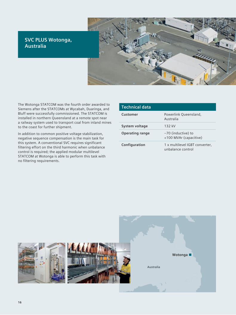
Technical dataCustomer Powerlink Queensland,
Australia
System voltage 132 kV
Operating range –70 (inductive) to +100 MVAr (capacitive)
Configuration 1 x multilevel IGBT converter, unbalance control
SVC PLUS Wotonga, Australia
The Wotonga STATCOM was the fourth order awarded to Siemens after the STATCOMs at Wycabah, Duaringa, and Bluff were successfully commissioned. The STATCOM is installed in northern Queensland at a remote spot near a railway system used to transport coal from inland mines to the coast for further shipment.
In addition to common positive voltage stabilization, negative sequence compensation is the main task for this system. A conventional SVC requires significant filtering effort on the third harmonic when unbalance control is required; the applied modular multilevel STATCOM at Wotonga is able to perform this task with no filtering requirements.
Australia
Wotonga
16

Technical dataCustomer Statnett, Norway
System voltage 132 kV / 50 Hz
Operating range –50 (inductive) to +50 MVAr (capacitive)
Configuration 1 x multilevel IGBT converter and coupling inductivity, both in prefab containers
SVC PLUS Sortland, Norway
The Lofoten Islands’ remoteness was causing voltage instabilities on the existing HV line. Therefore, a fast compensation device was required close to the town of Sortland. Siemens was awarded the contract for an SVC PLUS STATCOM because solution featured several benefits for this specific use case. Reducing local construction and installation activities to a minimum and finishing the work before the early start of winter were the driving forces behind prefabricating as many system parts as possible.
Siemens’ STATCOM SVC PLUS has all electrical equipment inside containers, including the coupling reactors, all interconnected by cables. No active airinsulated parts are installed in the yard, which provides optimal protection from the harsh environment, including vermin attacks. This solution also eliminated the need for an expensive and resourceconsuming building.
Oslo
Norway
Sweden
Finland
Russia
Sortland
17

The best of two solutions: the Hybrid STATCOMA Hybrid STATCOM is the logical progression that combines the existing SVC PLUS and conventional SVC technologies to provide a solution for both symmetrical and unsymmetrical operating ranges.
The versatile and economical solutionWhile SVC PLUS has many advantages compared with other reactive power compensation technologies, its operating range is always symmetrical due to the nature of its electrical design. For asymmetrical operating ranges, a Hybrid STATCOM is extended by either TSR or TSC. Siemens created the Hybrid STATCOM to meet the increasing demand for SVC PLUS technology in projects that require an unsymmetrical operation range. Because the thyristor branches are switched rather than controlled, no additional harmonics are generated – and therefore no filters are needed.
The Hybrid STATCOM concept has already been implemented several times when challenging project requirements demanded a smart solution.
The key features of the Hybrid STATCOM are:• Customized operating range• Space optimization• No filter required due to modular
multilevel converter technology• Very low electric losses• Reduced complexity of the configuration
compared to classic SVCs
Hybrid STATCOM V/I characteristic 1 x VSC + 1 x TSC
continuous operating area classic SVC
continuous operating area SVC PLUS branch
extended operating area with TSC branch
timelimited operating area SVC PLUS (2 x 1 sec.)
1 Transformer
2 SVC PLUS converter branch
3 TSC (Thyristor Switched Capacitor) capacitor branch
capacitive
–0.5 0.5
0.5
1.0
1.0 Iprim [pu]
Vprim [pu]
–1.0
inductive
18

Technical dataCustomer Long Island Power Authority
(LIPA), NY, USA
System voltage 138 kV / 60 Hz
Operating range –50 (inductive) to +150 MVAr (capacitive)
Configuration 1 multilevel IGBT converter 1 TSC
Hybrid STATCOM Holtsville, USA
The Holtsville Hybrid STATCOM is one of two installations that the Long Island Power Authority awarded to Siemens. Both Hybrids stabilize the voltage and provide reactive power support to the grid in Long Island, New York. During summer peaks in particular, the Hybrid STATCOM optimally meets the severe undervoltage performance requirements. The solution also excels in offering very low electrical losses as well as significant space savings compared with the conventional technology. All of these features made the Hybrid STATCOM the most powerful and economical solution for this use case.
Holtsville
WildwoodNew York City
New Jersey
New York Connecticut
Rhode Island
Massachusetts
1
2 3
HV
MV
19

SynCon: Answering new challenges to grid stabilityWith the everincreasing share of renewable power generation and the simultaneous shutdown of large conventional or nuclear power plants for environmental, economic, social, and political reasons, most power grids are experiencing a decreasing level of inertia and shortcircuit power.
Rotating phase shifters for short-circuit powerThe contribution of (hightech) power electronics, PV or wind power generation is generally limited or nil with respect to inertia or shortcircuit power – yet these are the keys to grid stability. Therefore, synchronous condenser solutions are experiencing a renaissance. These solutions use a generator to provide the necessary inertia by means of its rotating mass while also providing or absorbing reactive power.
A synchronous condenser solution comprises a generator that is connected to the transmission network through a transformer. It is started by either an electric motor or a static frequency converter. Once operating speed is achieved, the generator is synchronized with the network and behaves like a synchronous motor with no load, providing reactive power and shortcircuit power to the transmission network. All solutions are based on proven, reliable, inhouse equipment.
The key features of synchronous condensers:• Shortcircuit power capability• Provides inertia to the transmission system• Reactive power compensationDirect aircooled generator
20

Bjæverskov was the first out of three turnkey synchronous condensers that Siemens delivered to Energinet.dk, the Danish transmission system operator. All three help stabilize the transmission system by providing the necessary shortcircuit power to the network.
The scope of delivery for the synchronous condenser solutions included a synchronous generator with brushless excitation, a generator stepup transformer, and the electrical auxiliary systems, such as control and protection systems, voltage regulators and startup systems. All main components are Siemens inhouse products. The directly aircooled generator in particular brings major advantages, like low maintenance and the highest possible efficiency.
Synchronous Condenser Bjæverskov, Denmark
Technical dataCustomer Energienet.dk, Denmark
System voltage 400 kV / 50 Hz
Operating range –150 (inductive) to +250 MVAr (capacitive)
Configuration Direct aircooled generator
Copenhagen
Sweden
Germany
Denmark
Bjaeverskov
21

Industrial compensationElectric arc furnaces in melt shops, rollingmill drives, ball/SAG mills at mines, large compressors, pumps, and other varying loads can cause significant disturbances to the feeding network that can result in penalties from the utility or even a shutdown of the process or plant. In simple cases, improvements to the power factor and harmonics by means of filter circuits is sufficient.
For fast varying loads, a dynamic reactive power compensator – an industrial SVC with a thyristorcontrolled reactor (TCR) – will be the right solution, often integrating filter circuits to reduce loadgenerated harmonics. Especially in arc furnaces, if a standard SVC system can’t fulfill tough flicker requirements, an even faster SVC PLUS system is the right solution. Using the same power electronics as utility SVCs, industrial SVCs have a specialized control system for the fastest possible reaction to a measured load current.
These systems not only reduce the negative impacts of varying plant loads, they can even result in savings in energy costs – and therefore pay off quickly. Based on our extensive process experience in melt shops and rolling mills and mining and other industries, we can:• reliably evaluate the potential disturbances
in a network configuration• support customers’ negotiations with utilities• select and implement the most technologically
and commercially appropriate compensation
Large power consumers are often a source of disturbance in the grid, resulting in poor system performance or even impairing processes due to power quality issues, including reactive power, voltage distortion/ harmonics, voltage variations, and flicker.
The main benefits of industrial compensation:• lmproved energy supply• Compliance with limit values• Short amortization
Power quality for industrial plants
22

Turnkey solutionsProfit from our turnkey FACTS solutions. We have decades of practical experience as a contractor and equipment manufacturer assuming responsibility for reliable power transmission systems on all voltage levels. Our turnkey FACTS solutions combine the latest technological innovations and proven excellence in project management. With our global centers of competence and branches all over the world, we create local value and ensure that Siemens experts are within close reach of every project to tap the numerous advantages of our transmission systems.• All technical, financial, and environmental aspects
of the system’s entire lifecycle accounted for• Customized solutions for the most challenging demands –
with proven Siemens technologies• Minimized financial and technical risk, no coordination
efforts• Unbiased consulting is guaranteed, because we have
all FACTS technologies in our portfolio (no need to concentrate on a specific product to find the best technical solution for your grid)
Transmission services With Siemens FACTS customer services, you can fully concentrate on your core competencies and rely on the optimal performance of your assets. Our service portfolio provides everything you need to meet or even exceed the highest demands on efficiency, flexibility, and quality of power supply, today and in the future. We help you leverage value drivers such as: • Transparency: Know the status and condition
of your assets and plan accordingly• Availability: Identify early warnings and proactively
avoid downtime• Performance: Optimize asset performance
for maximum success• Operations management: We can even assume
full responsibility for operating your assets
Comprehensive FACTS services for troublefree operation
From technical clarifications to onsite support and turnkey solutions, our FACTS services portfolio helps you optimize your assets and their performance throughout their entire service life – with comprehensive solutions out of one hand.
23
Published by Siemens AG 2016
Energy Management Division Freyeslebenstrasse 1 91058 Erlangen, Germany
For more information, please contact our Customer Support Center. Phone: +49 180 524 70 00 Fax: +49 180 524 24 71 (Charges depending on provider) Email: [email protected]
Article No. EMTS-B10018-00-7600 Printed in Germany Dispo 30003 TH 263160391 BR 1116
Subject to changes and errors. The information given in this document only contains general descriptions and/or performance features which may not always specifically reflect those described, or which may undergo modification in the course of further development of the products. The requested performance features are binding only when they are expressly agreed upon in the concluded contract.


![FlexCore: Massively Parallel and Flexible … Massively Parallel and Flexible Processing for Large MIMO Access Points ... [Verilog],"GPU[CUDA/ C],"CPU](https://img.pdfslide.us/doc/110x75/5aa9f6e27f8b9a86188d7f92/flexcore-massively-parallel-and-flexible-massively-parallel-and-flexible-processing.jpg)