Embed Size (px)
Citation preview
User Manual LTU Orion 2
1
FlexDSL ORION 2(+)
LTU DEVICES TECHNICAL DESCRIPTION AND OPERATIONS MANUAL Version 1.5 Document name UM_Flexdsl-LTU-Orion2_V1-5.Doc Revision 18. November 2008

User Manual LTU Orion 2
2
© Copyright ©2008 by FlexDSL Telecommunications AG. The content of this publication may not be reproduced in any part or as a whole, transcribed, stored in a retrieval system, translated into any language, or transmitted in any form or by any means, electronic, mechanical, magnetic, optical, chemical, photocopying, manual, or otherwise, without the prior written permission of FlexDSL Telecommunications AG. Published FlexDSL Telecommunications AG. All rights reserved.
User Manual LTU Orion 2
3
VERSION CONTROL .................................................................................................................. 7
SAFETY REGULATIONS ............................................................................................................ 8
EU DIRECTIVE 2002/96/EC AND EN50419 ............................................................................... 8
1 SELECTION GUIDE ............................................................................................................. 9
2 INTRODUCTION ................................................................................................................. 10
3 TECHNICAL DESCRIPTION .............................................................................................. 11 3.1 Application and general information about FlexDSL Orion 2 devices .......................... 11 3.2 Main features of FlexDSL Orion 2 devices .................................................................. 12 3.3 Description of FlexDSL Orion 2 LTU devices .............................................................. 13
3.3.1 Remote power supply, wetting current- supply and consumption modes ............. 15 3.3.1.1 Electrical safety regulations when using the remote power supply ............... 15 3.3.1.2 Compatibility of wetting current supply and remote power supply modes ..... 15 3.3.1.3 Remote power & wetting- current supply and consumption modes .............. 16
3.3.2 Description of FlexDSL Orion 2 interfaces ............................................................ 18 3.3.2.1 xDSL interface ............................................................................................... 18
3.3.2.1.1 Master/Slave .............................................................................................. 18 3.3.2.1.2 Multipair modes .......................................................................................... 18 3.3.2.1.3 Reservation ................................................................................................ 20 3.3.2.1.4 Automatic configuration of a link ................................................................ 24
3.3.2.2 E1 interface (2 Mbit/s G.703/G.704) .............................................................. 26 3.3.2.2.1 Transparent and ITU-T G.704 .................................................................... 26 3.3.2.2.2 CRC4 (cyclic redundancy check) ............................................................... 26 3.3.2.2.3 AIS Generation (alarm indication signal) ................................................... 26 3.3.2.2.4 AIS Detection ............................................................................................. 27 3.3.2.2.5 Е1 clock modes .......................................................................................... 27
3.3.2.3 Ethernet interface .......................................................................................... 28 3.3.3 An integrated switch of 64-kbit/s time slots ........................................................... 31
3.3.3.1 E1 mode (transmission of only time slots of E1 streams) .............................. 31 3.3.3.2 Mode of simultaneous transmission of time slots of E1 and Ethernet data ... 32
3.3.4 Test loops ............................................................................................................. 34 3.3.4.1 Analog Loopback ........................................................................................... 34 3.3.4.2 Performance monitoring ................................................................................ 35 3.3.4.3 G.826 performance monitoring ...................................................................... 35
3.3.5 BERT test ............................................................................................................. 36 3.4 Alarm indication ........................................................................................................... 36
3.4.1 LEDs ..................................................................................................................... 36 3.4.2 Alarm LEDs ........................................................................................................... 38
3.5 Management of FlexDSL Orion 2 devices ................................................................... 40 3.5.1 Management of FlexDSL Orion 2 with the RS232 interface ................................. 40 3.5.2 Management of FlexDSL Orion 2 devices with Ethernet interfaces ..................... 40
3.5.2.1 Telnet ............................................................................................................. 40 3.5.2.2 WEB .............................................................................................................. 42 3.5.2.3 SNMP ............................................................................................................ 46
4 PROGRAMMING GUIDE .................................................................................................... 49 4.1 Command structure ..................................................................................................... 49 4.2 Orion 2 software ........................................................................................................... 51 4.3 Configuration storage and application ......................................................................... 51 4.4 Groups of commands requiring confirmation ............................................................... 53 4.5 Command syntax ......................................................................................................... 53 4.6 Commands ................................................................................................................... 54
4.6.1 Main Menu ............................................................................................................ 54 4.6.1.1 System invitation ........................................................................................... 54
4.6.2 General Commands .............................................................................................. 55 4.6.2.1 <H> command ............................................................................................... 55
User Manual LTU Orion 2
4
4.6.2.2 <CONNECT N:1..13/R> command ................................................................ 55 4.6.2.3 <LINK [SN/00/FE]> > command .................................................................... 55 4.6.2.4 <LINKCLEAR> command .............................................................................. 55
4.6.3 Performance management menu ......................................................................... 56 4.6.3.1 <H> command ............................................................................................... 56 4.6.3.2 <TCPIP> command ....................................................................................... 56 4.6.3.3 <MAC> command .......................................................................................... 58 4.6.3.4 <G826> command ......................................................................................... 59 4.6.3.5 <G826 Е1> command ................................................................................... 60 4.6.3.6 <ALLG826> command .................................................................................. 61 4.6.3.7 <RESETG826> command ............................................................................. 61 4.6.3.8 <RESETALLG826> command ...................................................................... 61 4.6.3.9 <LINKSTAT> command ................................................................................ 62 4.6.3.10 <ALARMLOG [N]> command ........................................................................ 62 4.6.3.11 <NETSTAT> command ................................................................................. 63 4.6.3.12 <RESETNETSTAT> command ..................................................................... 63 4.6.3.13 <M> command ............................................................................................... 63 4.6.3.14 <H> command ............................................................................................... 63
4.6.4 Fault and maintenance management menu ......................................................... 64 4.6.4.1 <H> command ............................................................................................... 64 4.6.4.2 <NM> command ............................................................................................ 65 4.6.4.3 <STATUS> command ................................................................................... 65 4.6.4.4 <STATUS ETH> command ........................................................................... 66 4.6.4.5 <MACTABLE> command .............................................................................. 67 4.6.4.6 <LOOP1 ON/OFF [N=1..4]> command ......................................................... 67 4.6.4.7 <LOOP2 [N:A/R] [ON/OFF]> command ........................................................ 67 4.6.4.8 <ALARM> command ..................................................................................... 68 4.6.4.9 <AСO [GROUP ON/OFF])> command .......................................................... 69 4.6.4.10 <STARTAL ON/OFF N> command ............................................................... 70 4.6.4.11 <RESTART [N=1..4]> command ................................................................... 70 4.6.4.12 <RESET> command ...................................................................................... 70 4.6.4.13 <SOFTUPDATE> command ......................................................................... 71 4.6.4.14 <SOFTCONFIRM> command ....................................................................... 71 4.6.4.15 <SOFTINFO> command ............................................................................... 71 4.6.4.16 <APPLY /ALL/NET/LINE> command ............................................................ 72 4.6.4.17 <CONFIRM> command ................................................................................. 72 4.6.4.18 <BACKUP> command ................................................................................... 72 4.6.4.19 <RESTORE> command ................................................................................ 72 4.6.4.20 <DIFF N/R/S/B N/R/S/B > command ............................................................. 73 4.6.4.21 <DUMP N/R/S/B > command ........................................................................ 73 4.6.4.22 <LOAD> command ........................................................................................ 74 4.6.4.23 <TLM > command ......................................................................................... 75 4.6.4.24 <TLM S [N:[Rnn-Rkk]] [ABC]> command ...................................................... 76 4.6.4.25 <BERT> command ........................................................................................ 76 4.6.4.26 <H> command ............................................................................................... 77 4.6.4.27 <START> command ...................................................................................... 77 4.6.4.28 <STOP> command ........................................................................................ 77 4.6.4.29 <TRACE > command .................................................................................... 77 4.6.4.30 <SHOW > command ..................................................................................... 78 4.6.4.31 <RES > command ......................................................................................... 78 4.6.4.32 <SET [E11-E12] [INT/EXT] > command ........................................................ 78 4.6.4.33 <TS [TX/RX] [0-31] > command .................................................................... 78 4.6.4.34 <PATD [2En/bitstring] > command ................................................................ 78 4.6.4.35 <CONF > command ...................................................................................... 78
4.6.5 Configuration management menu ........................................................................ 79 4.6.5.1 <H> command ............................................................................................... 79 4.6.5.2 <CONFIG / R / N / S / B > command ............................................................. 80 4.6.5.3 <MASTER ON/OFF [N = 1..4]> command .................................................... 83 4.6.5.4 <EXT ON/OFF [N = 1..4]> command ............................................................ 83 4.6.5.5 < MASTER ON/OFF N command .................................................................. 83 4.6.5.6 <BASERATE K/AUTO [N=1..4]> command .................................................. 84 4.6.5.7 <PAM 16/32/64 [N]> command ..................................................................... 84 4.6.5.8 <PAYLOAD list/NONE [N=1..4]> command .................................................. 84
User Manual LTU Orion 2
5
4.6.5.9 <ANNEX A/B/AB [N=1..4]> command ........................................................... 85 4.6.5.10 <SETCLOCK list [N=1..4]> command ........................................................... 85 4.6.5.11 <MULTIPAIR [MODE]> command ................................................................. 85 4.6.5.12 <RESERVE [list]>, <RESERVE [list] [list]> command ................................... 86 4.6.5.13 <POWER ON/OFF [N=1..4]> command ........................................................ 86 4.6.5.14 <RPPROT T/OFF [SEC/MIN]> command ..................................................... 86 4.6.5.15 <G704 ON/OFF [N]> command ..................................................................... 86 4.6.5.16 <CRC4 ON/OFF [N]> command .................................................................... 87 4.6.5.17 <AISGEN ON/OFF [N]>, <AISDET ON/OFF [N]> commands ....................... 87 4.6.5.18 <DSLTS list/NONE [N=1..4]> command ........................................................ 87 4.6.5.19 <WANTS [list] [N=1..4]> command (Ethernet via E1) .................................... 87 4.6.5.20 <E1CLOCK [DSL/RX/EXT] [N]> command ................................................... 88 4.6.5.21 <PASSWORD USER/ADMIN> command ..................................................... 88 4.6.5.22 <ID N> command .......................................................................................... 88 4.6.5.23 <DEFAULT> command ................................................................................. 88 4.6.5.24 <DEFAULT EVERYTHING> command ......................................................... 88 4.6.5.25 <SERNUM> command .................................................................................. 89 4.6.5.26 <LICENSE [LICENSE_KEY]> command ....................................................... 89 4.6.5.27 <GSCOMPAT> command ............................................................................. 89 4.6.5.28 <NMTHR> command ..................................................................................... 89 4.6.5.29 <LATHR> command ...................................................................................... 89 4.6.5.30 <MODE N> command ................................................................................... 89 4.6.5.31 <H> command ............................................................................................... 90 4.6.5.32 <NETCONFIG [R/N/S/B]> command ............................................................ 91 4.6.5.33 <INTERFACE NAME COMMAND PARAM > command ............................... 93 4.6.5.34 <ETHSD 10/100/AUTO H/F [N=1..4]> command .......................................... 94 4.6.5.35 <SLICING SIZE> command .......................................................................... 94 4.6.5.36 <SETIP X.X.X.X> command .......................................................................... 94 4.6.5.37 <NETMASK X.X.X.X> command ................................................................... 95 4.6.5.38 <GATEWAY X.X.X.X> command .................................................................. 95 4.6.5.39 <VID> command ............................................................................................ 95 4.6.5.40 <V2T {[VIQ] [QoS]}|OFF > command ............................................................ 95 4.6.5.41 <TRAPIP ADD/DEL X.X.X.X> command ...................................................... 95 4.6.5.42 <COMMUNITY> command ........................................................................... 95 4.6.5.43 <SNMPSET ON/OFF> command .................................................................. 96 4.6.5.44 <ALARMTRAP ON/OFF> command ............................................................. 96 4.6.5.45 <NETDEFAULT> command .......................................................................... 96 4.6.5.46 <M> command ............................................................................................... 96
5 SOFTWARE DOWNLOADING ........................................................................................... 97 5.1 Software loading via the RS232 port with the help of the Flash Loader program ........ 97 5.2 Software loading via the COM port (the 1K-Xmodem protocol) ................................. 100 5.3 Software loading via Ethernet (1K-Xmodem and Telnet) ........................................... 104
6 SERVICE INSTRUCTIONS .............................................................................................. 105 6.1 General requirements ................................................................................................ 105 6.2 Evaluation of the quality of the digital channel and operation parameters ................. 106
7 APPENDICES ................................................................................................................... 107 7.1 Example 1 of configuration of Orion 2 devices .......................................................... 107
7.1.1 Configuration of the FlexDSL Orion 2 device at the Central Office premises. .... 107 7.1.2 Configuration of the FlexDSL Orion 2 device at the Customer Premises. .......... 108 7.1.3 Configuration of the FlexDSL Orion 2 regenerator at the Regenerator Point. .... 108
7.2 Example 1 of configuration of Orion 2 devices .......................................................... 109 7.2.1 Configuration of the FlexDSL Orion 2 device at the Central Office premises. .... 109 7.2.2 Configuration of the FlexDSL Orion 2 device at the Customer Premises. .......... 110 7.2.3 Configuration of the FlexDSL Orion 2 regenerator at the Regenerator Point. .... 111
7.3 Connectors’ description ............................................................................................. 112 7.3.1 “Ethernet” connector ........................................................................................... 112 7.3.2 “xDSL” connector ................................................................................................ 112 7.3.3 E1 120 Ohm Connector ...................................................................................... 113 7.3.4 E1 75 Ohm In / Out Connectors ......................................................................... 113

User Manual LTU Orion 2
6
7.3.5 “Monitor” connector (MinRack only) .................................................................... 113 7.3.6 “-48VDС” connector (MinRack only) ................................................................... 114
8 TECHNICAL SPECIFICATION ......................................................................................... 115 8.1 Interfaces ................................................................................................................... 115
8.1.1 xDSL Line Interface ............................................................................................ 115 8.1.2 E1 Line Interface ................................................................................................. 115 8.1.3 Monitor (RS232) Interface .................................................................................. 115 8.1.4 Ethernet .............................................................................................................. 115
8.2 Power Supply ............................................................................................................. 116 8.3 Environmental ............................................................................................................ 116
8.3.1 Climatic Conditions ............................................................................................. 116 8.3.2 Safety / EMC ....................................................................................................... 116
8.4 Physical Dimensions and Weight ............................................................................... 116
User Manual LTU Orion 2
7
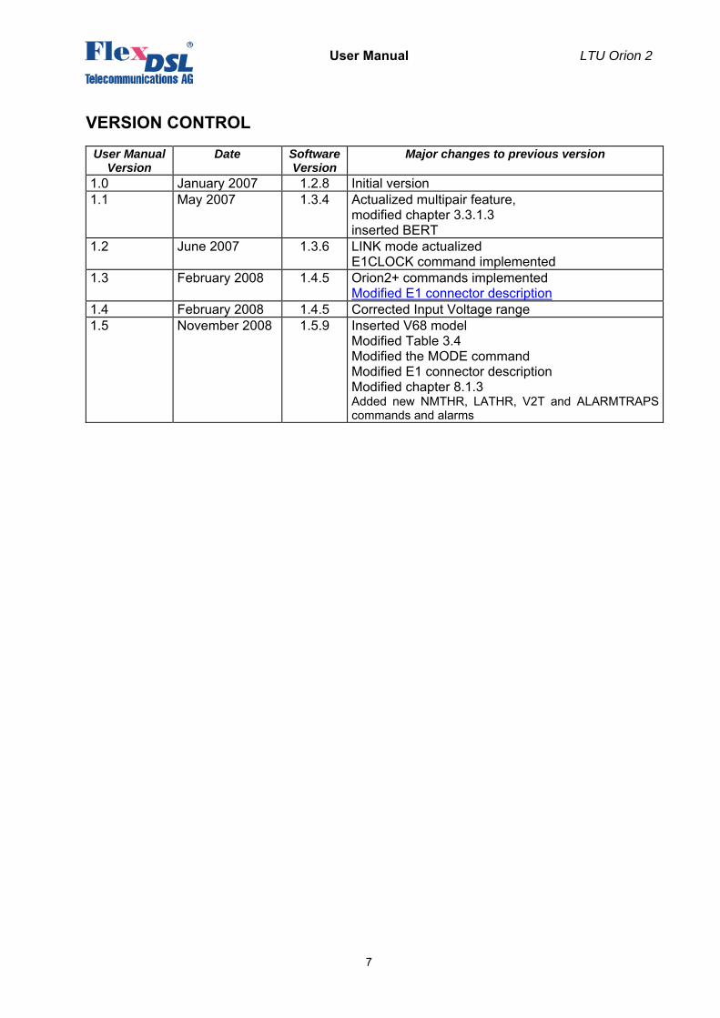
VERSION CONTROL
User Manual Version
Date Software Version
Major changes to previous version
1.0 January 2007 1.2.8 Initial version 1.1 May 2007 1.3.4 Actualized multipair feature,
modified chapter 3.3.1.3 inserted BERT
1.2 June 2007 1.3.6 LINK mode actualized E1CLOCK command implemented
1.3 February 2008 1.4.5 Orion2+ commands implemented Modified E1 connector description
1.4 February 2008 1.4.5 Corrected Input Voltage range 1.5 November 2008 1.5.9 Inserted V68 model
Modified Table 3.4 Modified the MODE command Modified E1 connector description Modified chapter 8.1.3 Added new NMTHR, LATHR, V2T and ALARMTRAPS commands and alarms

User Manual LTU Orion 2
8
SAFETY REGULATIONS IF THE UNIT IS NOT USED IN ACCORDANCE TO REGULATIONS DESCRIBED AND DEFINED IN THE CHAPTERS ”TECHNICAL DESCRIPTION” AND “TECHNICAL SPECIFICATIONS”, FLEXDSL TELECOMMUNICATIONS AG REFUSES TO TAKE ANY RESPONSIBILITY. FURTHERMORE, NO WARRANTY IS GRANTED IN SUCH CASE! ITS ONLY ALLOWED TO USE EXTERNAL POWER SUPPLYS THAT ARE APPROVED ACOORDING TO THE SAFETY STANDARD IEC/EN 60950-1. ITS ONLY ALLOWED TO USE THE UNITS WITH SUBRACKS OR MINIRACK UNITS SUPPLYED FROM FLEXDSL TELECOMMUNICATIONS AG. THE RACK HAS TO BE CONNECTED PERMANENTLY TO A RELIABLE PROTECTIVE ERTH CONDUCTOR. THE LTU UNIT HAS TO BE FIXED TO THE RACK PERMANENTLY WITH THE TWO PANEL SCREWS. INCORRECT USE OF THIS DEVICE, USE IN ANY OTHER ENVIRONMENT AND/OR HOUSING THAN PROVIDED BY FLEXDSL MIGHT LEAD TO HARMFUL CONDITIONS. FAILURE TO FOLLOW THESE PRECAUTIONS MAY RESULT IN DEATH, SEVERE INJURY OR PROPERTY DAMAGE. Please read this manual carefully before operating the system. Installation of this equipment has to be done by qualified personnel only.
EU DIRECTIVE 2002/96/EC AND EN50419
This equipment is marked with the above recycling symbol. It means that at the end of the life of the equipment you must dispose of it separately at an appropriate collection point and not place it in the normal domestic unsorted waste stream. (European Union only)
User Manual LTU Orion 2
9
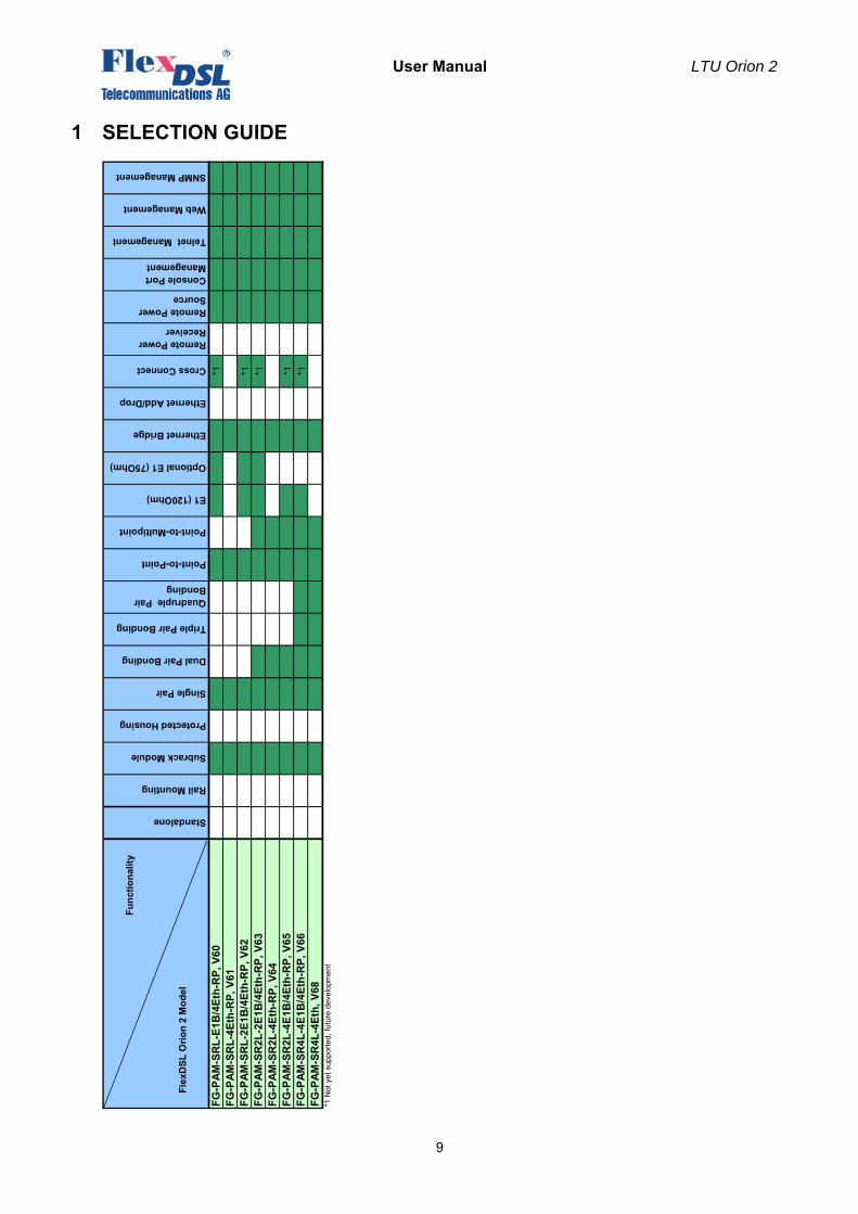
1 SELECTION GUIDE
Func
tiona
lity…
..
F
lexD
SL O
rion
2 M
odel
FG-P
AM-S
RL-
E1B
/4Et
h-R
P, V
60*1
FG-P
AM-S
RL-
4Eth
-RP,
V61
FG-P
AM-S
RL-
2E1B
/4Et
h-R
P, V
62*1
FG-P
AM-S
R2L
-2E1
B/4
Eth-
RP,
V63
*1FG
-PAM
-SR
2L-4
Eth-
RP,
V64
FG-P
AM-S
R2L
-4E1
B/4
Eth-
RP,
V65
*1FG
-PAM
-SR
4L-4
E1B
/4Et
h-R
P, V
66*1
FG-P
AM-S
R4L
-4Et
h, V
68*1
Not
yet
sup
porte
d, fu
ture
dev
elop
men
t
Standalone
Subrack Module
Protected Housing
Single Pair
Rail Mounting
Ethernet Bridge
Dual Pair Bonding
E1 (120Ohm)
Optional E1 (75Ohm)
Quadruple Pair Bonding
Point-to-Point
Point-to-Multipoint
Triple Pair Bonding
Ethernet Add/Drop
Cross Connect
Telnet Management
SNMP Management
Remote Power Receiver
Remote Power Source
Console Port Management
Web Management
User Manual LTU Orion 2
10
2 INTRODUCTION
The present document describes devices of the FlexDSL Orion 2 LTU family. The document contains the technical description of the devices, installation, configuration, and operation instructions. Appendices containing additional information about the system are also an integral part of the present document.
Warning!! Before starting operating the equipment, read carefully PART 5 of the present document. The guarantee will not be granted to the device malfunctioning or damaged due to failure to comply with the requirements stated in the Section related to “Service Instructions” of the present document.
Warning!! An example of fast configuration of the equipment is described in Appendix 6.1 of the present document.
User Manual LTU Orion 2
11
3 TECHNICAL DESCRIPTION
3.1 Application and general information about FlexDSL Orion 2 devices
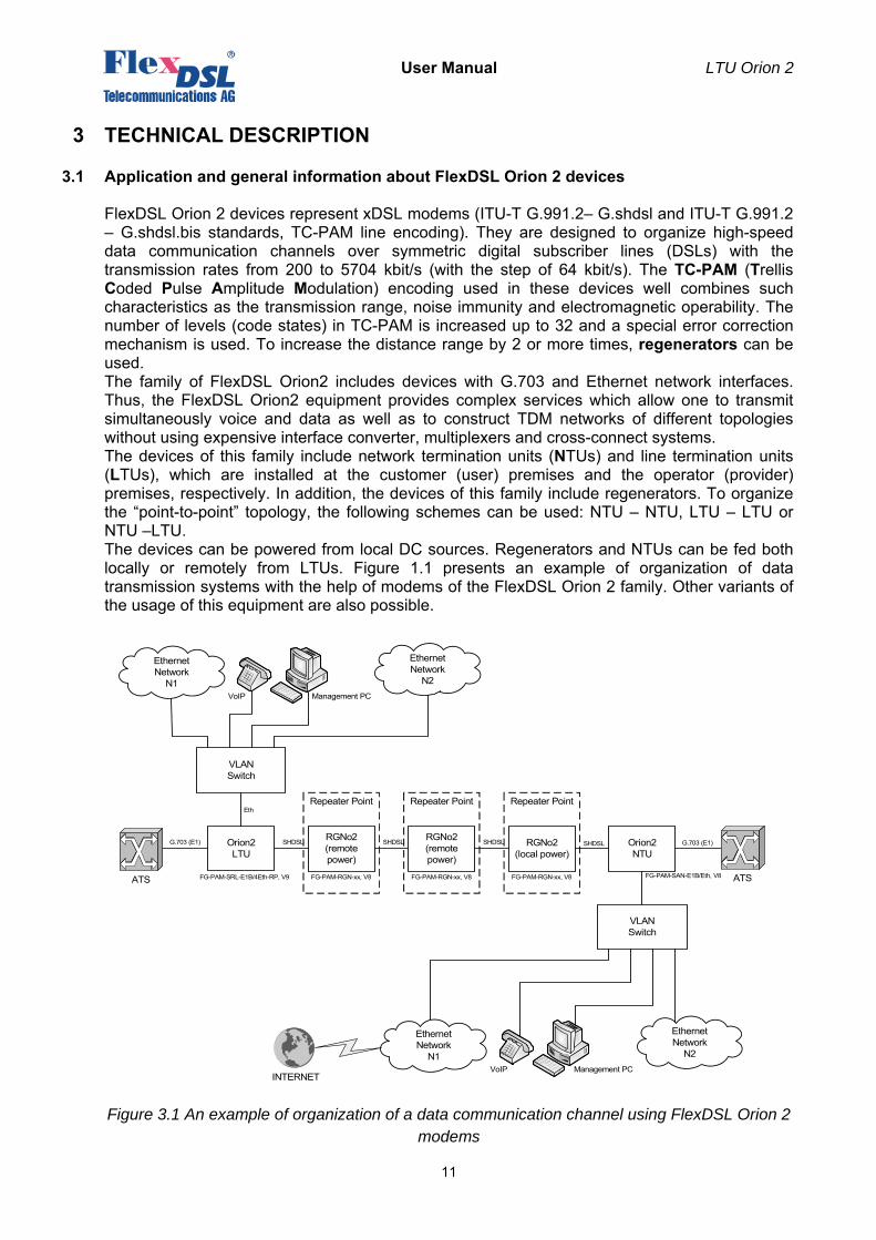
FlexDSL Orion 2 devices represent xDSL modems (ITU-T G.991.2– G.shdsl and ITU-T G.991.2 – G.shdsl.bis standards, TC-PAM line encoding). They are designed to organize high-speed data communication channels over symmetric digital subscriber lines (DSLs) with the transmission rates from 200 to 5704 kbit/s (with the step of 64 kbit/s). The TC-PAM (Trellis Coded Pulse Amplitude Modulation) encoding used in these devices well combines such characteristics as the transmission range, noise immunity and electromagnetic operability. The number of levels (code states) in TC-PAM is increased up to 32 and a special error correction mechanism is used. To increase the distance range by 2 or more times, regenerators can be used. The family of FlexDSL Orion2 includes devices with G.703 and Ethernet network interfaces. Thus, the FlexDSL Orion2 equipment provides complex services which allow one to transmit simultaneously voice and data as well as to construct TDM networks of different topologies without using expensive interface converter, multiplexers and cross-connect systems. The devices of this family include network termination units (NTUs) and line termination units (LTUs), which are installed at the customer (user) premises and the operator (provider) premises, respectively. In addition, the devices of this family include regenerators. To organize the “point-to-point” topology, the following schemes can be used: NTU – NTU, LTU – LTU or NTU –LTU. The devices can be powered from local DC sources. Regenerators and NTUs can be fed both locally or remotely from LTUs. Figure 1.1 presents an example of organization of data transmission systems with the help of modems of the FlexDSL Orion 2 family. Other variants of the usage of this equipment are also possible.
Figure 3.1 An example of organization of a data communication channel using FlexDSL Orion 2 modems
Orion2 LTU
RGNo2(remote power)
RGNo2 (remote power)
RGNo2 (local power)
Orion2NTU
SHDSL SHDSL SHDSL SHDSL
FG-PAM-SRL-E1B/4Eth-RP, V9 FG-PAM-SAN-E1B/Eth, V8FG-PAM-RGN-xx, V8 FG-PAM-RGN-xx, V8 FG-PAM-RGN-xx, V8
VLAN Switch
Ethernet Network
N2
Ethernet Network
N1
Eth
ATS
G.703 (E1) G.703 (E1)
ATS
Management PCVoIP
VLAN Switch
Ethernet Network
N2
Ethernet Network
N1Management PCVoIP
INTERNET
Repeater Point Repeater Point Repeater Point
User Manual LTU Orion 2
12
Notations in the figure: • ATS: a private automatic branch exchange;
• E1: a 2048-kbit/s digital flow structured according to ITU-T Rec. G.704;
• Management PC: a personal computer used to configure the system;
• Vlan Switch: a switch of Ethernet packets supporting the Vlan function (IEEE 802.1q);
• VoIP: devices of IP telephony (VOICE over IP);
• Ethernet Network: local Ethernet network;
• Orion2 LTU: FlexDSL Orion2 line termination unit;
• Orion2 NTU: FlexDSL Orion2 network termination unit;
• RGNo2: FlexDSL Orion2 regenerator.
The devices of this family have different mechanic designs: SubRack – a unit to be inserted into a 19’’ FlexGain shelf; MiniRack – a 1U (44.5 mm) unit to be inserted into a 19’’ cabinet; Stand Alone – a desktop unit; IP-67 – a unit in a water-proof plastic or silumin housing (class IP-67); XCVR – a unit to be inserted into a hermetic steel housing. The devices have the following possibilities for monitoring and management: • Local management and control of remote devices and regenerators – VT 100;
• Local management and control of remote devices and regenerators – Telnet session;
• Operation in complex networks under the unified management system – support of SNMP.
The use of the Flash memory as the ROM provides an easy upgrade of the software. xDSL modems are powered from a grounded primary DC source (38 … 78 V) or remotely. Modems are designed to be used in-doors under the following environmental conditions: - temperature of ambient air – from -5 … +45°C; - relative air humidity – from 5% … 85% at +25°C.
3.2 Main features of FlexDSL Orion 2 devices
FlexDSL Orion 2 modems represent the next generation of modems of the FlexDSL Orion family and have the following features: • A new type of line encoding – TC-PAM32 (TC-PAM16 is also supported).
• Duplex data transmission over one symmetrical pair at 5.7 Mbit/s.
• Simultaneous transmission of the TDM traffic and Ethernet data.
• The 802.1q protocol.
• Different ways of system configuration (for example, remote configuration of devices via Telnet).
• Embedded WEB interface.
• The SNMP protocol.
• Possibility of storing several configurations in the device’s EEPROM in order to download the previous settings of the system.
• Two levels of system users: administrator and user, protected with passwords.
• The use of the modern circuit printed boards, chips and components.
• Extended reliability of the equipment.
User Manual LTU Orion 2
13
3.3 Description of FlexDSL Orion 2 LTU devices
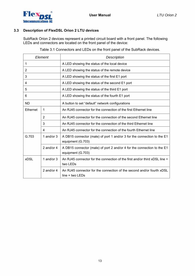
SubRack Orion 2 devices represent a printed circuit board with a front panel. The following LEDs and connectors are located on the front panel of the device:
Table 3.1 Connectors and LEDs on the front panel of the SubRack devices.
Element Description
1 A LED showing the status of the local device
2 A LED showing the status of the remote device
3 A LED showing the status of the first E1 port
4 A LED showing the status of the second E1 port
5 A LED showing the status of the third E1 port
6 A LED showing the status of the fourth E1 port
ND A button to set “default” network configurations
Ethernet 1 An RJ45 connector for the connection of the first Ethernet line
2 An RJ45 connector for the connection of the second Ethernet line
3 An RJ45 connector for the connection of the third Ethernet line
4 An RJ45 connector for the connection of the fourth Ethernet line
G.703 1 and/or 3 A DB15 connector (male) of port 1 and/or 3 for the connection to the E1 equipment (G.703)
2 and/or 4 A DB15 connector (male) of port 2 and/or 4 for the connection to the E1 equipment (G.703)
xDSL 1 and/or 3 An RJ45 connector for the connection of the first and/or third xDSL line + two LEDs
2 and/or 4 An RJ45 connector for the connection of the second and/or fourth xDSL line + two LEDs
User Manual LTU Orion 2
14
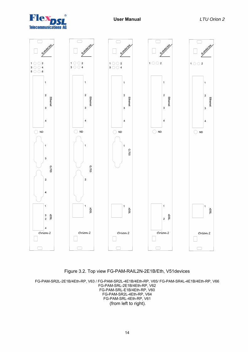
Figure 3.2. Top view FG-PAM-RAIL2N-2E1B/Eth, V51devices
FG-PAM-SR2L-2E1B/4Eth-RP, V63 / FG-PAM-SR2L-4E1B/4Eth-RP, V65/ FG-PAM-SR4L-4E1B/4Eth-RP, V66 FG-PAM-SRL-2E1B/4Eth-RP, V62 FG-PAM-SRL-E1B/4Eth-RP, V60
FG-PAM-SR2L-4Eth-RP, V64 FG-PAM-SRL-4Eth-RP, V61
(from left to right).

User Manual LTU Orion 2
15
3.3.1 Remote power supply, wetting current- supply and consumption modes
The wetting current supply and remote power supply modes can be changed by using jumpers and the management PC.
3.3.1.1 Electrical safety regulations when using the remote power supply
Despite the safe voltage on each wire with respect to the ground (<120 Volts), the use the remote power supply has to be done strictly according to the following rules: • When working with DSL lines make sure that the remote power is switched off.
• The insulation of cable pairs, junctions (junction boxes, plinths, etc.) should correspond to norms and standards of the network;
3.3.1.2 Compatibility of wetting current supply and remote power supply modes
The table of compatibility of the wetting current supply and remote power supply modes is presented below. The devices operating in pairs should be configured for mutual operation (“√” – compatible). The use of the mode «-» is not recommended because it may cause: high power consumption, degradation of communication (communication stability), the use of additional safety measures. The mode “incompatible” (inc) will not allow the devices to establish communication (because in this case one or both devices will be de-energized). Wetting current supply
and remote power supply modes
NTU or regenerator LTU
Remote power
consumption
Local power
Remote power supply
Wetting current supply
Wetting current
consumption
No
NTU or
Regenerator
Power DP inc inc √ inc inc inc
Power LP inc √ - - √ √
LTU Remote power supply
√ - Х Х Х -
Wetting current supply
inc - Х Х √ -
Remote power consumption
inc √ Х √ √ √
No inc √ - - √ √
Table 3.2 Compatible operation of remote power supply and wetting current supply modes.
Warning! To prevent the FAILURE OF THE EQUIPMENT, the use of “X” modes IS STRICTLY PROHIBITED!
User Manual LTU Orion 2
16
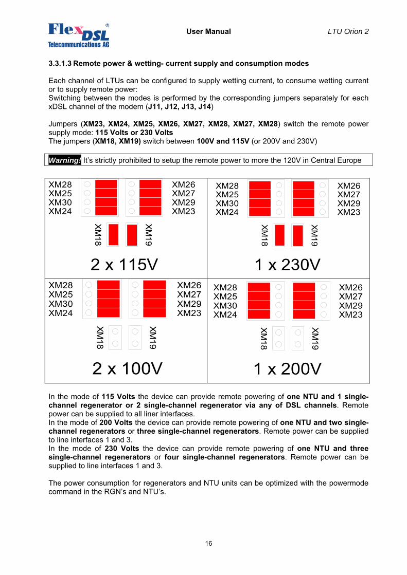
3.3.1.3 Remote power & wetting- current supply and consumption modes
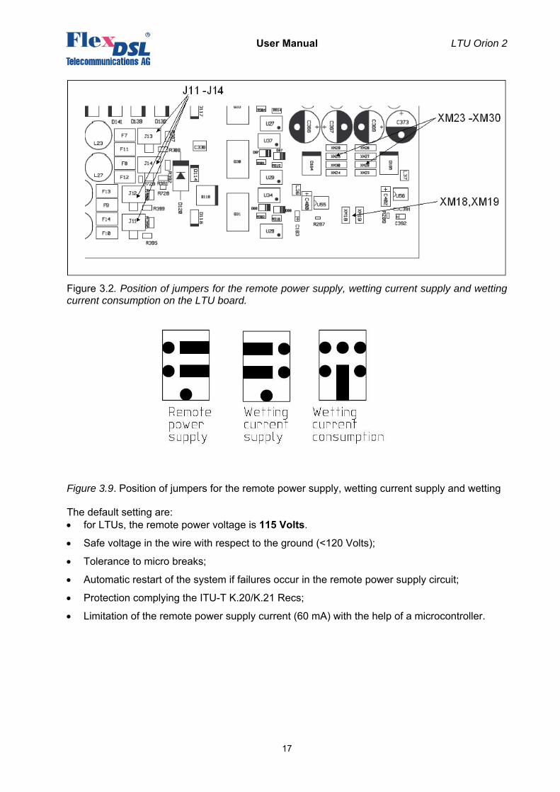
Each channel of LTUs can be configured to supply wetting current, to consume wetting current or to supply remote power: Switching between the modes is performed by the corresponding jumpers separately for each xDSL channel of the modem (J11, J12, J13, J14) Jumpers (XM23, XM24, XM25, XM26, XM27, XM28, XM27, XM28) switch the remote power supply mode: 115 Volts or 230 Volts The jumpers (XM18, XM19) switch between 100V and 115V (or 200V and 230V)
Warning! It’s strictly prohibited to setup the remote power to more the 120V in Central Europe
XM27XM26
XM29XM23
XM25XM28
XM30XM24
2 x 115V
XM
18
XM
19
XM27XM26
XM29XM23
XM25XM28
XM30XM24
1 x 230V
XM
18
XM
19
XM27XM26
XM29XM23
XM25XM28
XM30XM24
2 x 100V
XM18
XM19
XM27XM26
XM29XM23
XM25XM28
XM30XM24
1 x 200V
XM
18
XM
19
In the mode of 115 Volts the device can provide remote powering of one NTU and 1 single- channel regenerator or 2 single-channel regenerator via any of DSL channels. Remote power can be supplied to all liner interfaces. In the mode of 200 Volts the device can provide remote powering of one NTU and two single-channel regenerators or three single-channel regenerators. Remote power can be supplied to line interfaces 1 and 3. In the mode of 230 Volts the device can provide remote powering of one NTU and three single-channel regenerators or four single-channel regenerators. Remote power can be supplied to line interfaces 1 and 3. The power consumption for regenerators and NTU units can be optimized with the powermode command in the RGN’s and NTU’s.
User Manual LTU Orion 2
17
Figure 3.2. Position of jumpers for the remote power supply, wetting current supply and wetting current consumption on the LTU board.
Figure 3.9. Position of jumpers for the remote power supply, wetting current supply and wetting The default setting are: • for LTUs, the remote power voltage is 115 Volts.
• Safe voltage in the wire with respect to the ground (<120 Volts);
• Tolerance to micro breaks;
• Automatic restart of the system if failures occur in the remote power supply circuit;
• Protection complying the ITU-T K.20/K.21 Recs;
• Limitation of the remote power supply current (60 mA) with the help of a microcontroller.
User Manual LTU Orion 2
18
3.3.2 Description of FlexDSL Orion 2 interfaces
3.3.2.1 xDSL interface
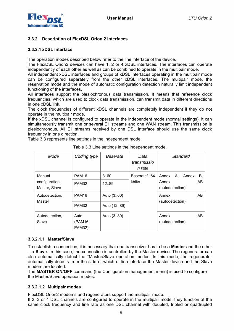
The operation modes described below refer to the line interface of the device. The FlexDSL Orion2 devices can have 1, 2 or 4 xDSL interfaces. The interfaces can operate independently of each other as well as can be combined to operate in the multipair mode. All independent xDSL interfaces and groups of xDSL interfaces operating in the multipair mode can be configured separately from the other xDSL interfaces. The multipair mode, the reservation mode and the mode of automatic configuration detection naturally limit independent functioning of the interfaces. All interfaces support the plesiochronous data transmission. It means that reference clock frequencies, which are used to clock data transmission, can transmit data in different directions in one xDSL link. The clock frequencies of different xDSL channels are completely independent if they do not operate in the multipair mode. If the xDSL channel is configured to operate in the independent mode (normal settings), it can simultaneously transmit one or several E1 streams and one WAN stream. This transmission is plesiochronous. All E1 streams received by one DSL interface should use the same clock frequency in one direction. Table 3.3 represents line settings in the independent mode.
Table 3.3 Line settings in the independent mode.
Mode Coding type Baserate Data transmissio
n rate
Standard
Manual configuration, Master, Slave
PAM16 3..60 Baserate* 64 kbit/s
Annex A, Annex B, Annex AB (autodetection)
PAM32 12..89
Autodetection, Master
PAM16 Auto (3..60) Annex AB (autodetection)
PAM32 Auto (12..89)
Autodetection, Slave
Auto (PAM16, PAM32)
Auto (3..89) Annex AB (autodetection)
3.3.2.1.1 Master/Slave
To establish a connection, it is necessary that one transceiver has to be a Master and the other – a Slave. In this case, the connection is controlled by the Master device. The regenerator can also automatically detect the “Master/Slave operation modes. In this mode, the regenerator automatically detects from the side of which of line interface the Master device and the Slave modem are located. The MASTER ON/OFF command (the Configuration management menu) is used to configure the Master/Slave operation modes.
3.3.2.1.2 Multipair modes
FlexDSL Orion2 modems and regenerators support the multipair mode. If 2, 3 or 4 DSL channels are configured to operate in the multipair mode, they function at the same clock frequency and line rate as one DSL channel with doubled, tripled or quadrupled
User Manual LTU Orion 2
19
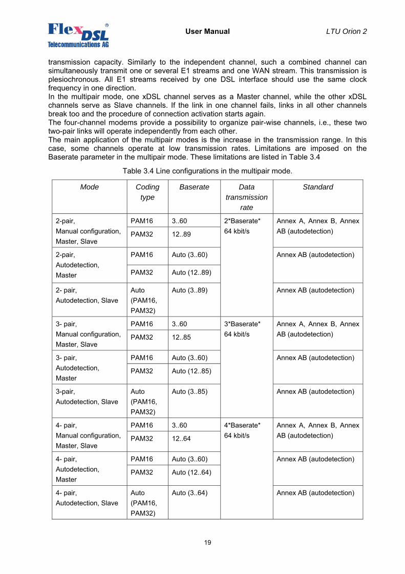
transmission capacity. Similarly to the independent channel, such a combined channel can simultaneously transmit one or several E1 streams and one WAN stream. This transmission is plesiochronous. All E1 streams received by one DSL interface should use the same clock frequency in one direction. In the multipair mode, one xDSL channel serves as a Master channel, while the other xDSL channels serve as Slave channels. If the link in one channel fails, links in all other channels break too and the procedure of connection activation starts again. The four-channel modems provide a possibility to organize pair-wise channels, i.e., these two two-pair links will operate independently from each other. The main application of the multipair modes is the increase in the transmission range. In this case, some channels operate at low transmission rates. Limitations are imposed on the Baserate parameter in the multipair mode. These limitations are listed in Table 3.4
Table 3.4 Line configurations in the multipair mode.
Mode Coding type
Baserate Data transmission
rate
Standard
2-pair, Manual configuration, Master, Slave
PAM16 3..60 2*Baserate* 64 kbit/s
Annex A, Annex B, Annex AB (autodetection) PAM32 12..89
2-pair, Autodetection, Master
PAM16 Auto (3..60) Annex AB (autodetection)
PAM32 Auto (12..89)
2- pair, Autodetection, Slave
Auto (PAM16, PAM32)
Auto (3..89) Annex AB (autodetection)
3- pair, Manual configuration, Master, Slave
PAM16 3..60 3*Baserate* 64 kbit/s
Annex A, Annex B, Annex AB (autodetection) PAM32 12..85
3- pair, Autodetection, Master
PAM16 Auto (3..60) Annex AB (autodetection)
PAM32 Auto (12..85)
3-pair, Autodetection, Slave
Auto (PAM16, PAM32)
Auto (3..85) Annex AB (autodetection)
4- pair, Manual configuration, Master, Slave
PAM16 3..60 4*Baserate* 64 kbit/s
Annex A, Annex B, Annex AB (autodetection) PAM32 12..64
4- pair, Autodetection, Master
PAM16 Auto (3..60) Annex AB (autodetection)
PAM32 Auto (12..64)
4- pair, Autodetection, Slave
Auto (PAM16, PAM32)
Auto (3..64) Annex AB (autodetection)
User Manual LTU Orion 2
20
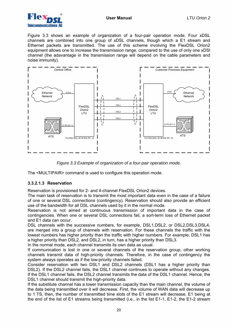
Figure 3.3 shows an example of organization of a four-pair operation mode. Four xDSL channels are combined into one group of xDSL channels, though which a E1 stream and Ethernet packets are transmitted. The use of this scheme involving the FlexDSL Orion2 equipment allows one to increase the transmission range, compared to the use of only one xDSl channel (the adavantage in the transmission range will depend on the cable parameters and noise immunity).
Figure 3.3 Example of organization of a four-pair operation mode.
The <MULTIPAIR> command is used to configure this operation mode.
3.3.2.1.3 Reservation
Reservation is provisioned for 2- and 4-channel FlexDSL Orion2 devices. The main task of reservation is to transmit the most important data even in the case of a failure of one or several DSL connections (contingency). Reservation should also provide an efficient use of the bandwidth for all DSL channels used by it in the normal mode. Reservation is not aimed at continuous transmission of important data in the case of contingencies. When one or several DSL connections fail, a sort-term loss of Ethernet packet and E1 data can occur. DSL channels with the successive numbers, for example, DSL1,DSL2, or DSL2,DSL3,DSL4, are merged into a group of channels with reservation. For these channels the traffic with the lowest numbers has higher priority than the traffic with higher numbers. For example, DSL1 has a higher priority than DSL2, and DSL2, in turn, has a higher priority than DSL3. In the normal mode, each channel transmits its own data as usual. If communication is lost in one or several channels of the reservation group, other working channels transmit data of high-priority channels. Therefore, in the case of contingency the system always operates as if the low-priority channels failed. Consider reservation with two DSL1 and DSL2 channels (DSL1 has a higher priority than DSL2). If the DSL2 channel fails, the DSL1 channel continues to operate without any changes. If the DSL1 channel fails, the DSL2 channel transmits the data of the DSL1 channel. Hence, the DSL1 channel should transmit the high-priority data. If the substitute channel has a lower transmission capacity than the main channel, the volume of the data being transmitted over it will decrease. First, the volume of WAN data will decrease up to 1 TS, then, the number of transmitted time slots of the E1 stream will decrease, E1 being at the end of the list of E1 streams being transmitted (i.e., in the list E1-1, E1-2, the E1-2 stream
FlexDSLOrion2
LTU
FG-PAM-SR2L-4E1B/4Eth-RP, V9
G.703 (E1-1) G.703 (E1-1)
ATS
Customer Premises EquipmentCentral Office
ETH1Ethernet Network
FlexDSL Orion2 LTU
ETH1 Ethernet Network
FG-PAM-SR4L-4E1B/4Eth-RP, V9
DSL2
DSL1
ATS
DSL4
DSL3
User Manual LTU Orion 2
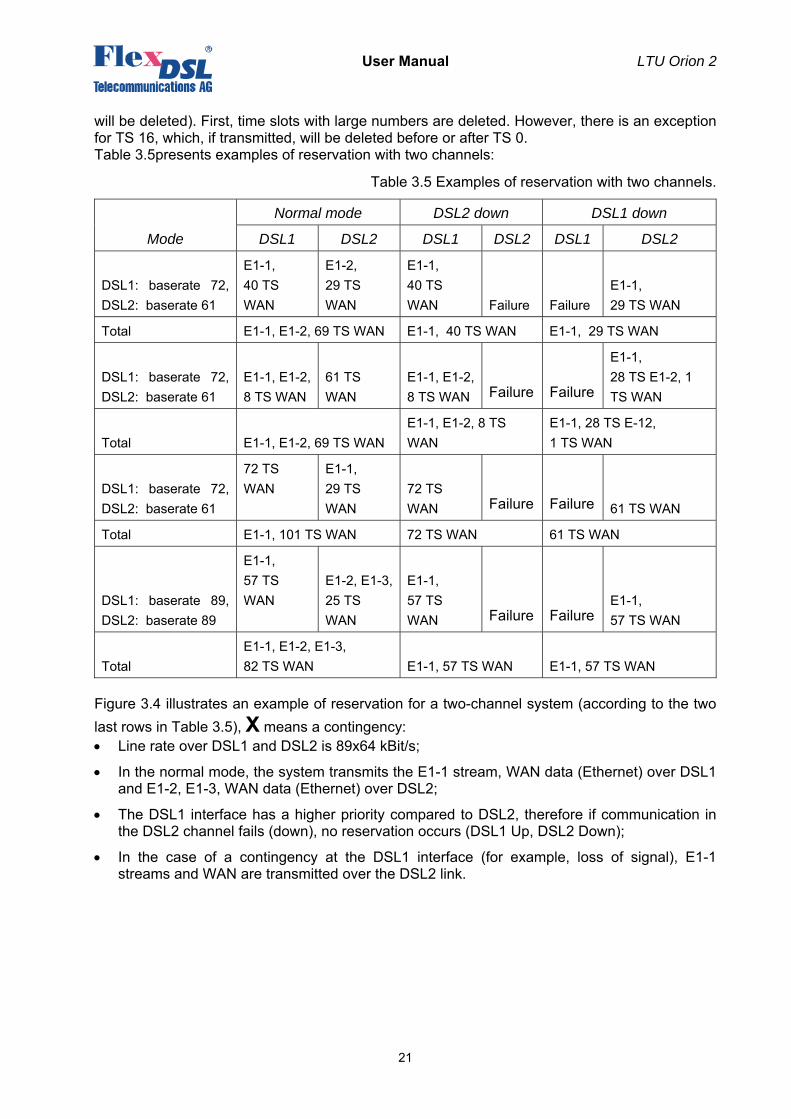
21
will be deleted). First, time slots with large numbers are deleted. However, there is an exception for TS 16, which, if transmitted, will be deleted before or after TS 0. Table 3.5presents examples of reservation with two channels:
Table 3.5 Examples of reservation with two channels.
Mode
Normal mode DSL2 down DSL1 down
DSL1 DSL2 DSL1 DSL2 DSL1 DSL2
DSL1: baserate 72, DSL2: baserate 61
E1-1, 40 TS WAN
E1-2, 29 TS WAN
E1-1, 40 TS WAN Failure Failure
E1-1, 29 TS WAN
Total E1-1, E1-2, 69 TS WAN E1-1, 40 TS WAN E1-1, 29 TS WAN
DSL1: baserate 72, DSL2: baserate 61
E1-1, E1-2, 8 TS WAN
61 TS WAN
E1-1, E1-2, 8 TS WAN Failure Failure
E1-1, 28 TS E1-2, 1 TS WAN
Total E1-1, E1-2, 69 TS WAN E1-1, E1-2, 8 TS WAN
E1-1, 28 TS E-12, 1 TS WAN
DSL1: baserate 72, DSL2: baserate 61
72 TS WAN
E1-1, 29 TS WAN
72 TS WAN Failure Failure 61 TS WAN
Total E1-1, 101 TS WAN 72 TS WAN 61 TS WAN
DSL1: baserate 89, DSL2: baserate 89
E1-1, 57 TS WAN
E1-2, E1-3,25 TS WAN
E1-1, 57 TS WAN Failure Failure
E1-1, 57 TS WAN
Total E1-1, E1-2, E1-3, 82 TS WAN E1-1, 57 TS WAN E1-1, 57 TS WAN
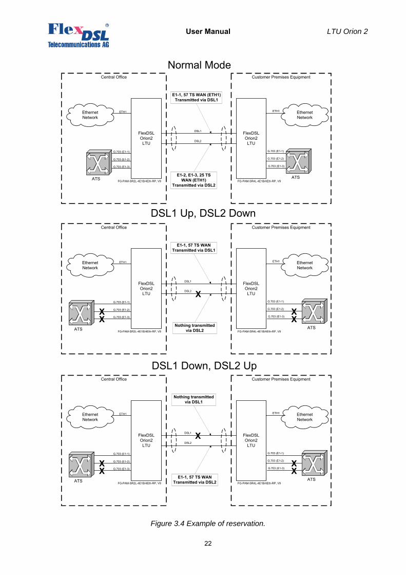
Figure 3.4 illustrates an example of reservation for a two-channel system (according to the two last rows in Table 3.5), X means a contingency: • Line rate over DSL1 and DSL2 is 89x64 kBit/s;
• In the normal mode, the system transmits the E1-1 stream, WAN data (Ethernet) over DSL1 and E1-2, E1-3, WAN data (Ethernet) over DSL2;
• The DSL1 interface has a higher priority compared to DSL2, therefore if communication in the DSL2 channel fails (down), no reservation occurs (DSL1 Up, DSL2 Down);
• In the case of a contingency at the DSL1 interface (for example, loss of signal), E1-1 streams and WAN are transmitted over the DSL2 link.
User Manual LTU Orion 2
22
Figure 3.4 Example of reservation.
FlexDSLOrion2 LTU
FG-PAM-SR2L-4E1B/4Eth-RP, V9
G.703 (E1-1) G.703 (E1-1)
Customer Premises EquipmentCentral Office
ETH1Ethernet Network
FlexDSL Orion2 LTU
ETH1 Ethernet Network
FG-PAM-SR4L-4E1B/4Eth-RP, V9
DSL1
DSL2
G.703 (E1-2)
G.703 (E1-3)
ATS
G.703 (E1-2)
G.703 (E1-3)
ATS
FlexDSLOrion2 LTU
FG-PAM-SR2L-4E1B/4Eth-RP, V9
G.703 (E1-1) G.703 (E1-1)
Customer Premises EquipmentCentral Office
ETH1Ethernet Network
FlexDSL Orion2 LTU
ETH1 Ethernet Network
FG-PAM-SR4L-4E1B/4Eth-RP, V9
DSL1
DSL2
G.703 (E1-2)
G.703 (E1-3)
G.703 (E1-2)
G.703 (E1-3)
ATSATS
XX
X
XX
E1-1, 57 TS WAN (ETH1)Transmitted via DSL1
E1-2, E1-3, 25 TS WAN (ETH1)
Transmitted via DSL2
Normal Mode
DSL1 Up, DSL2 Down
E1-1, 57 TS WANTransmitted via DSL1
Nothing transmitted via DSL2
FlexDSLOrion2 LTU
FG-PAM-SR2L-4E1B/4Eth-RP, V9
G.703 (E1-1) G.703 (E1-1)
Customer Premises EquipmentCentral Office
ETH1Ethernet Network
FlexDSL Orion2 LTU
ETH1 Ethernet Network
FG-PAM-SR4L-4E1B/4Eth-RP, V9
DSL1
DSL2
G.703 (E1-2)
G.703 (E1-3)
G.703 (E1-2)
G.703 (E1-3)
ATSATS
XX
X
XX
DSL1 Down, DSL2 Up
Nothing transmitted via DSL1
E1-1, 57 TS WANTransmitted via DSL2
User Manual LTU Orion 2
23
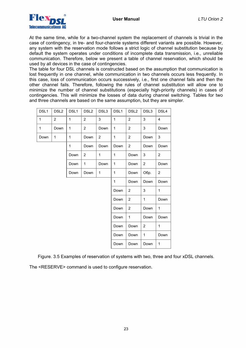
At the same time, while for a two-channel system the replacement of channels is trivial in the case of contingency, in tre- and four-channle systems different variants are possible. However, any system with the reservation mode follows a strict logic of channel substitution because by default the system operates under conditions of incomplete data transmission, i.e., unreliable communication. Therefore, below we present a table of channel reservation, which should be used by all devices in the case of contingencies. The table for four DSL channels is constructed based on the assumption that communication is lost frequently in one channel, while communication in two channels occurs less frequently. In this case, loss of communication occurs successively, i.e., first one channel fails and then the other channel fails. Therefore, following the rules of channel substitution will allow one to minimize the number of channel substitutions (especially high-priority channels) in cases of contingencies. This will minimize the losses of data during channel switching. Tables for two and three channels are based on the same assumption, but they are simpler.
DSL1 DSL2 DSL1 DSL2 DSL3 DSL1 DSL2 DSL3 DSL4
1 2 1 2 3 1 2 3 4
1 Down 1 2 Down 1 2 3 Down
Down 1 1 Down 2 1 2 Down 3
1 Down Down Down 2 Down Down
Down 2 1 1 Down 3 2
Down 1 Down 1 Down 2 Down
Down Down 1 1 Down Обр. 2
1 Down Down Down
Down 2 3 1
Down 2 1 Down
Down 2 Down 1
Down 1 Down Down
Down Down 2 1
Down Down 1 Down
Down Down Down 1
Figure. 3.5 Examples of reservation of systems with two, three and four xDSL channels.
The <RESERVE> command is used to configure reservation.
User Manual LTU Orion 2
24
3.3.2.1.4 Automatic configuration of a link
FlexDSL Orion2 devices allow one to configure the link in accordance with the Master-modem configuration. This mode is available for the following links: • Point-point single-channel links;
• Point-point multichannel links with independent channels;
• Star-topology multichannel links;
• Point-point multipair links;
• Point-point two-channel two-pair links;
• Star-topology two-pair links;
• Links with regenerators.
Note: Automatic configuration of link reservation is not supported. When the automatic configuration is used, the Slave modems and regenerators receive nearly all configuration parameters for DSL and E1 from the link. In a majority of cases they require minimum configurations, which allows one not duplicate manually configurations to all other devices in the link. Such configurations as the number of E1 time slots transmitted over DSL, CRC4 and G704 modes should not be configured on all devices because they are received automatically from the link. The system of automatic configuration operates as follows: • The CP side (Slave) automatically adjusts so that to correspond to the stream structure
received from the CO side (Master), and not to cause permanent losses of user data;
• If the CP side (Slave) cannot adjust correspondingly, it displays a RCONF alarm and sends a message to the remote terminal device. If configurations of terminal devices (Master and Slave) do not coincide, the RCONF alarm is displayed. RCONF stands for remote urgent alarm.
The link is adjusted to the channel structure in the direction from the Master to the Slave: • The stream structure is configured on the Master device;
• The regenerator, which the next in the link, receives this structure and configures itself according to it;
• The next regenerator receives the structure from the previous regenerator and performs configuration according to it;
• The Slave device receives the stream structure from the regenerator, which the last one in the link, and also performs configuration;
• When the Slave device receives configuration, it distributes the received E1 streams to its E1 ports. If the number of ports is not enough, it displays the RCONF alarm and does not change the configuration of E1 streams. If the E1 streams are not distributed, the Slave device receives configurations of WAN. Therefore, the integrity of the Ethernet link is supported.
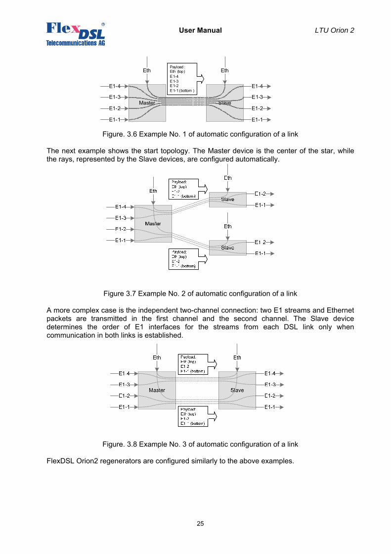
The RCONF alarm (which is displayed by the <ALARM> command and stands for the remote urgent alarm) means that the local and remote equipment have incompatible configurations. The RCONF alarm is automatically not displayed if a DSL link, in which it was detected, fails. If the device operates in the CA mode (automatic configuration of a link), the alarm is not displayed when the device finally adjusts to the CO side (Master). We consider several examples of automatic configuration of the FlexDSL Orion2 system. Four fractional E1 streams and Ethernet data are transmitted over one DSL link.
User Manual LTU Orion 2
25
Figure. 3.6 Example No. 1 of automatic configuration of a link
The next example shows the start topology. The Master device is the center of the star, while the rays, represented by the Slave devices, are configured automatically.
Figure 3.7 Example No. 2 of automatic configuration of a link
A more complex case is the independent two-channel connection: two E1 streams and Ethernet packets are transmitted in the first channel and the second channel. The Slave device determines the order of E1 interfaces for the streams from each DSL link only when communication in both links is established.
Figure. 3.8 Example No. 3 of automatic configuration of a link
FlexDSL Orion2 regenerators are configured similarly to the above examples.
Master
E1-4
E1-3
E1-2
E1-1
Eth
SlaveE1-3
E1-2
E1-1
Eth
E1-4
Payload :Eth (top)E1-4E1-3E1-2E1-1 (bottom )
User Manual LTU Orion 2
26
3.3.2.2 E1 interface (2 Mbit/s G.703/G.704)
The operation modes are described below refer to the E1 interfaces.
3.3.2.2.1 Transparent and ITU-T G.704
In the transparent mode, the E1 data will be transmitted over the DSL without any changes. The transparent mode is only possible for transmission rates of no less than 2056 Kbit/s when transmitting one E1 stream in this mode and of no less than 4104 Kbit/s when transmitting both E1 streams in this mode. In the G.704 mode (framing according to ITU-T G.704), the E1 data stream is processed by the E1 framer, which is incorporated in the block of E1 network interfaces. In this case, from 1 to 32 time slots of the corresponding E1 stream can be transmitted over the DSL line. The G704 OFF/ONN command (the Configuration management menu) is used to enable/disable the Transparent/ITU-T G.704 modes.
3.3.2.2.2 CRC4 (cyclic redundancy check)
The CRC4 mode enables the error performance monitoring of the E1 network interface with the help of a cyclic redundancy check. If the mode is enabled, the modem synchronizes with CRC4 sub-multiframes at the E1 output and displays information about CRC errors. In this case the modem regenerates E1 CRC4 sub-multiframes and checksum words in the outgoing E1 stream. If the mode is disabled, the modem transmits transparently CRC4 sub-multiframes and checksum words in the case if the generation of the zero time slot is deactivated. If the TS0GEN mode is activated, the zero time slot is generated without CRC4 sub-multiframes and checksum words.
3.3.2.2.3 AIS Generation (alarm indication signal)
If this mode is enabled, AISs will be transmitted to the E1 side under the following conditions: • the loss of the line signal from the remote device or loss of frame alignment on the DSL
side;
• the remote device receives an AIS over E1 interface, which is configured to transmit data from E1 to DSL. This mode is enabled if only the AIS Detection mode is enabled on the remote device (see below). If modems (A and B) transmit two E1 streams, then if AIS is received over the first E1 channel of the A modem, in the B modem the AIS will be generated over the first channel. And if AIS is received over the second E1 channel of the A modem, in the B modem the AIS will be generated over the second channel.
The AISGEN ON/OFF command (the Configuration management menu) is used to enable/disable the AIS Generation mode.
Warning! If the AIS Generation mode is disabled, the signal at the output of the E1 interface will be absent in the case of losing communication in the DSL line (except for time slots of this interface dedicated to carry Ethernet data).
Warning! If a part of time slots of one of E1 network interfaces is used to transmit Ethernet data, AISs will not be generated for this interface.
User Manual LTU Orion 2
27
3.3.2.2.4 AIS Detection
If this mode is enabled, the receiving of an AIS over the E1 interface will cause the following: • a non-urgent alarm will appear;
• AIS will be transmitted to the remote device of the DSL.
The AISDET ON/OFF command (the Configuration management menu) is used to enable/disable the AIS Detection mode.
Warning! It is recommended to enable the AIS Detection and AIS Generation modes.
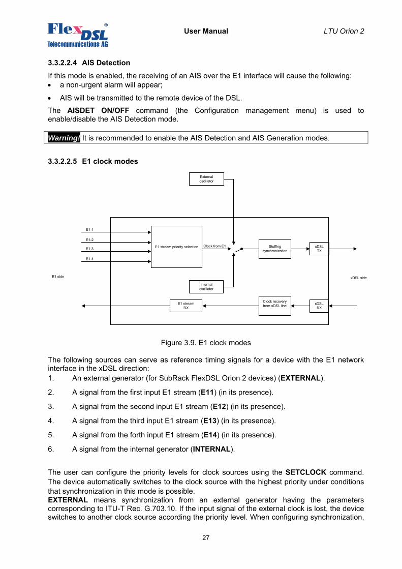
3.3.2.2.5 Е1 clock modes
Figure 3.9. Е1 clock modes
The following sources can serve as reference timing signals for a device with the E1 network interface in the xDSL direction: 1. An external generator (for SubRack FlexDSL Orion 2 devices) (EXTERNAL).
2. A signal from the first input E1 stream (E11) (in its presence).
3. A signal from the second input E1 stream (E12) (in its presence).
4. A signal from the third input E1 stream (E13) (in its presence).
5. A signal from the forth input E1 stream (E14) (in its presence).
6. A signal from the internal generator (INTERNAL).
The user can configure the priority levels for clock sources using the SETCLOCK command. The device automatically switches to the clock source with the highest priority under conditions that synchronization in this mode is possible. EXTERNAL means synchronization from an external generator having the parameters corresponding to ITU-T Rec. G.703.10. If the input signal of the external clock is lost, the device switches to another clock source according the priority level. When configuring synchronization,
E1 stream priority selection
E1 streamRX
Stuffing synchronization
Internal oscillator
Clock recovery from xDSL line
xDSLTX
xDSLRX
xDSL sideE1 side
Clock from E1
External oscillator
E1-4
E1-3
E1-2
E1-1
User Manual LTU Orion 2
28
this external clock should have the highest priority. If the external generator is absent, it should not be included in the priority list. Note: Stand Alone and MiniRack devices cannot use an external clock source. E11, E12, E13 and E14 mean synchronization from one of the input E1 stream. If the stream, which serves as a clock, is lost, the device switches to another clock according to the priority level. These clocks should be listed as the second, third, fourth and fifth clocks in the priority list, if the external clock generator is used. Otherwise, they will serve as primary clock sources and be listed as the first, second, third, fourth and fifth ones, respectively, in the priority list, if the external clock generator is absent. INTERNAL means synchronization from an internal clock source. This clock source should be the last one in the priority list (but in the absence of other clock sources, for example, when only Ethernet data are transmitted, this source can be the primary and the only one). Switching between clock sources occurs within 100 ms, after synchronization is lost.
3.3.2.3 Ethernet interface
FlexDSL Orion 2 devices have an IEEE 802.3 interface to connect local Ethernet networks. The Ethernet networks use the method for access to the data transmission medium, which is called carrier-sense-multiply-access with collision detection (CSMA/CD). Modems and regenerators of the FlexDSL Orion 2 family supports the VLAN protocol (Virtual Local Area Network – IEEE 802.1Q). A virtual network represents a group of network nodes, whose traffic, including the broadcast traffic, is completely isolated from other network nodes. This means that the frame transmission between different virtual segments by using MAC address is impossible independent of the type of the address, i.e., unique, group or broadcast one. At the same time frames are transmitted within the virtual network by using the Ethernet switching technique. By using the VLAN protocol one can unite the network users into separate logic groups, for example, in order to decrease the traffic load in the network, to improve the safety and to simplify management. Organization of virtual networks allows one to decrease the load in the network, because the broadcast traffic will be transmitted not to the entire network but to members of the VLAN sender. Due to the fact that the members of different VLANs can exchange information via a router, which allows the traffic to be controlled rather simply, the use of VLANs provides a high level of security. In addition, introduction of changes in the network structure is simplified because one should configure the modem port instead of configuring the work station to which the modem is connected. To construct VLAN networks and to provide the priority in the data transmission, an extended Ethernet frame is used, which contains an additional VLAN tag of length of 2 bytes. The tag includes the number of the VLAN to which the packet belongs and its priority level. Some types of traffic should be sent via the network without any delays, for example, real-time video at video conferences or IP traffic. To provide the necessary quality of this traffic, the devices support the Ethernet traffic priority according to the IEEE 802.1P protocol, the so-called QoS (Quality of Service) method. Analyzing the content of the header of the Ethernet frame, the internal switch obtains information about the necessary priority of this application and places data to the corresponding queue of the output port. The FlexDSL Orion 2 equipment supports two priority queues when sending packets – a high priority queue and a low priority queue. According to it, all Ethernet traffic can be divided into groups of high priority (for example, VoIP
User Manual LTU Orion 2
29
traffic transmission, or control and management channel) and groups of low priority (for example, LAN1 and LAN2). Devices of the FlexDSL Orion 2 family support two types of VLANs: • Port-Based VLAN (VLAN switching at port level). VLAN numbers and QoS priorities are
assigned to ports (see below);
• Address-Based VLAN (VLAN switching at the level of MAC addresses). A static table of special MAC addresses is organized (see below).
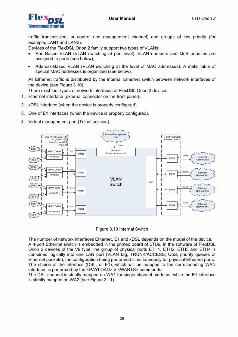
All Ethernet traffic is distributed by the internal Ethernet switch between network interfaces of the device (see Figure 3.10). There exist four types of network interfaces of FlexDSL Orion 2 devices:
1. Ethernet interface (external connector on the front panel).
2. xDSL interface (when the device is properly configured).
3. One of E1 interfaces (when the device is properly configured).
4. Virtual management port (Telnet session).
Figure 3.10 Internal Switch
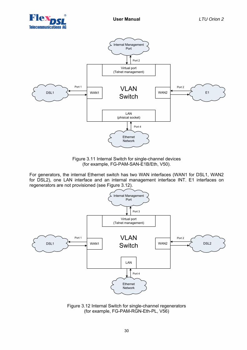
The number of network interfaces Ethernet, E1 and xDSL depends on the model of the device. A 4-port Ethernet switch is embedded in the printed board of LTUs. In the software of FlexDSL Orion 2 devices of the V9 type, the group of physical ports ETH1, ETH2, ETH3 and ETH4 is combined logically into one LAN port (VLAN tag, TRUNK/ACCESS, QoS, priority queues of Ethernet packets), the configuration being performed simultaneously for physical Ethernet ports. The choice of the interface (DSL, or E1), which will be mapped to the corresponding WAN interface, is performed by the <PAYLOAD> и <WANTS> commands. The DSL channel is strictly mapped on WA1 for single-channel modems, while the E1 interface is strictly mapped on WA2 (see Figure 3.11).
VLAN Switch
Internal ManagementPort
Virtual port (Telnet management)WAN1
WAN2
WAN3
WAN4
LAN
Ethernet Network №1
Port 1
Port 2
Port 3
Port 4
Port 6
Port 5
ETH1
ETH2
ETH3
ETH4
Ethernet Network №2
Port 7
Ethernet Network №3
Port 8
Ethernet Network №4
Port 9
DSL1<PAYLOAD>
<WANTS>
DSL2<PAYLOAD>
<WANTS>
DSL3<PAYLOAD>
<WANTS>
DSL4<PAYLOAD>
<WANTS>
4-port Hardware Ethernet Switch
DSL (<PAYLOAD>) or E1 (<WANTS>)
Selection for WAN Payload
E1-1
E1-2
E1-3
E1-4
User Manual LTU Orion 2
30
Figure 3.11 Internal Switch for single-channel devices (for example, FG-PAM-SAN-E1B/Eth, V50).
For generators, the internal Ethernet switch has two WAN interfaces (WAN1 for DSL1, WAN2 for DSL2), one LAN interface and an internal management interface INT. E1 interfaces on regenerators are not provisioned (see Figure 3.12).
Figure 3.12 Internal Switch for single-channel regenerators (for example, FG-PAM-RGN-Eth-PL, V56)
VLAN SwitchDSL1
Internal ManagementPort
Virtual port (Telnet management)
WAN1 WAN2 DSL2
Port 1 Port 2
Port 3
LAN
Ethernet Network
Port 4
VLAN Switch
DSL1
Internal ManagementPort
Virtual port (Telnet management)
WAN1
Ethernet Network
LAN(phisical socket)
WAN2 E1
Port 1
Port 4
Port 2
Port 2
User Manual LTU Orion 2
31
A group of LAN Ports (Ethernet interface) means that a connector (or connectors) is located on the front panel of the device. This port can serve both as a Trunk port and an Access port. The Trunk port is a port at the input and output of which all present packets have the VLAN format, namely, the Ethernet frame with a header, determining the number of the VLAN and QoS (Quality of Service) to which the IP packet belongs. Special equipment, which supports the VLAN, is connected to the Trunk port. A PC with a standard network interface card cannot be connected to the Trunk port. The Access port is a port at the input and output of which all present packets have a standard Ethernet format (without the additional two bytes for the header). A PC with a standard network interface card can be connected to the Access port. Ethernet packets of the VLAN format are always transmitted over the xDSL or E1 interfaces in FlexDSL Orion 2 devices. In this case, the data of Assess ports are first transformed into Ethernet packets of the VLAN format according to the specified rules and then are transmitted over the line interface. A VLAN number and a QoS priority level, which are used by default to convert Ethernet packets into the VLAN format, are assigned to the Access port. In addition, every unit contains a table of static MAC addresses of devices, so that each device can have a VLAN number and a QoS priority level (a table of special MAC addresses). This table can contain up to 8 MAC addresses. If a packet is received from the Access port, and the MAC address of the packet sender is in this table, a header with the necessary VLAN number and the QoS priority will be assigned to this packet before transmitting it to the Trunk port. Otherwise, a default VLAN number and QoS priority will be assigned to the packet. Physical ports (if there are some of them) are united into a LAN group in the device software. All physical Ethernet interfaces (the LAN group) have identical VLAN and QoS settings. A possibility is also provisioned to configure separately the transmission rate and duplex for each physical interface (ETH1 – ETH4). A group of DSL ports (WAN1 – WAN4) (xDSL interface) means that Ethernet data can be mapped onto the specified time slots of the xDSL interface by using the switch of 64 kbit/s time slots. In this case, this port always serves as a Trunk port, i.e., data received from Access ports are first transformed into Ethernet packets of the VLAN format according to the rules specified and then are transmitted over the xDSL interface. A group of E1 ports (WAN1 – WAN4) (E1 interface) means that that Ethernet data can be mapped onto the specified time slots of the E1 interface by using the switch of 64-kbit/s time slots. In this case, this port always serves as a Trunk port. A virtual management port (INT) (Virtual management port) is an internal device management program. IP-address of this device is the logical address of the management program. For example, to open a session for managing a remote device (i.e., to exchange data between a control and management PC and the device program), the IP-address of this device should be specified in the Telnet program. At the physical layer, the MAC address of the device is also the management program address, which is contained in the Ethernet frame. Note: As a rule the data of the management port have the highest priority (example, QoS = 7).
3.3.3 An integrated switch of 64-kbit/s time slots
3.3.3.1 E1 mode (transmission of only time slots of E1 streams)
In this mode, only time slots of E1 streams are transmitted over xDSL lines. Time slots of the E1 stream are transmitted in the xDSL frame according to ITU-T Rec. G.991.2. The table presented below contains examples of the correspondence between the data transmission rates for a modem and transmitted time slots of the E1 stream for this transmission mode.
User Manual LTU Orion 2
32
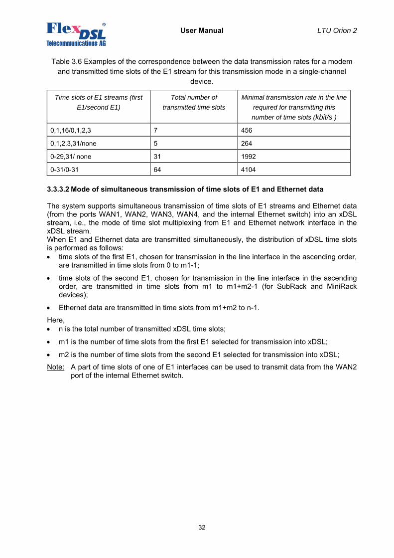
Table 3.6 Examples of the correspondence between the data transmission rates for a modem and transmitted time slots of the E1 stream for this transmission mode in a single-channel
device.
Time slots of E1 streams (first E1/second E1)
Total number of transmitted time slots
Minimal transmission rate in the line required for transmitting this number of time slots (kbit/s )
0,1,16/0,1,2,3 7 456
0,1,2,3,31/none 5 264
0-29,31/ none 31 1992
0-31/0-31 64 4104
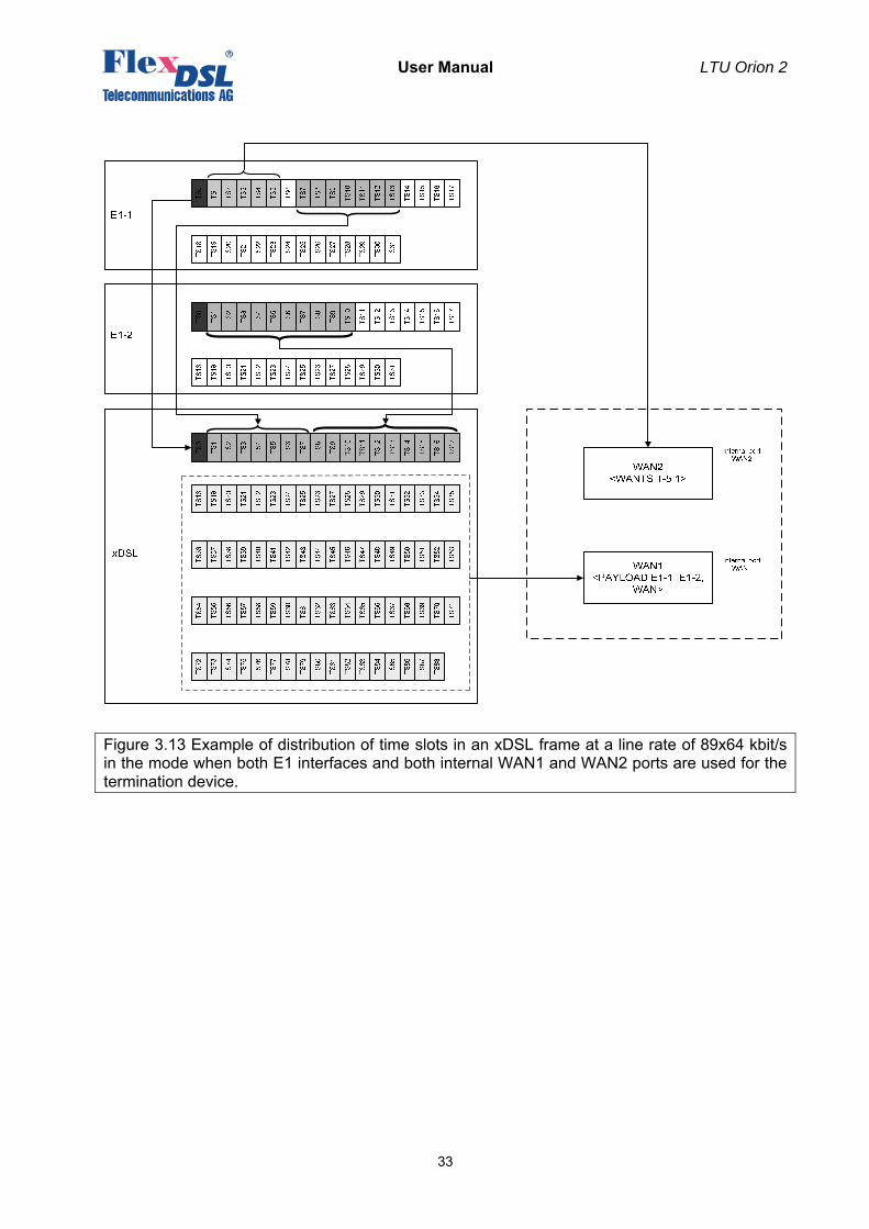
3.3.3.2 Mode of simultaneous transmission of time slots of E1 and Ethernet data
The system supports simultaneous transmission of time slots of E1 streams and Ethernet data (from the ports WAN1, WAN2, WAN3, WAN4, and the internal Ethernet switch) into an xDSL stream, i.e., the mode of time slot multiplexing from E1 and Ethernet network interface in the xDSL stream. When E1 and Ethernet data are transmitted simultaneously, the distribution of xDSL time slots is performed as follows: • time slots of the first E1, chosen for transmission in the line interface in the ascending order,
are transmitted in time slots from 0 to m1-1;
• time slots of the second E1, chosen for transmission in the line interface in the ascending order, are transmitted in time slots from m1 to m1+m2-1 (for SubRack and MiniRack devices);
• Ethernet data are transmitted in time slots from m1+m2 to n-1.
Here, • n is the total number of transmitted xDSL time slots;
• m1 is the number of time slots from the first E1 selected for transmission into xDSL;
• m2 is the number of time slots from the second E1 selected for transmission into xDSL;
Note: A part of time slots of one of E1 interfaces can be used to transmit data from the WAN2 port of the internal Ethernet switch.
User Manual LTU Orion 2
33
Figure 3.13 Example of distribution of time slots in an xDSL frame at a line rate of 89x64 kbit/s in the mode when both E1 interfaces and both internal WAN1 and WAN2 ports are used for the termination device.
User Manual LTU Orion 2
34
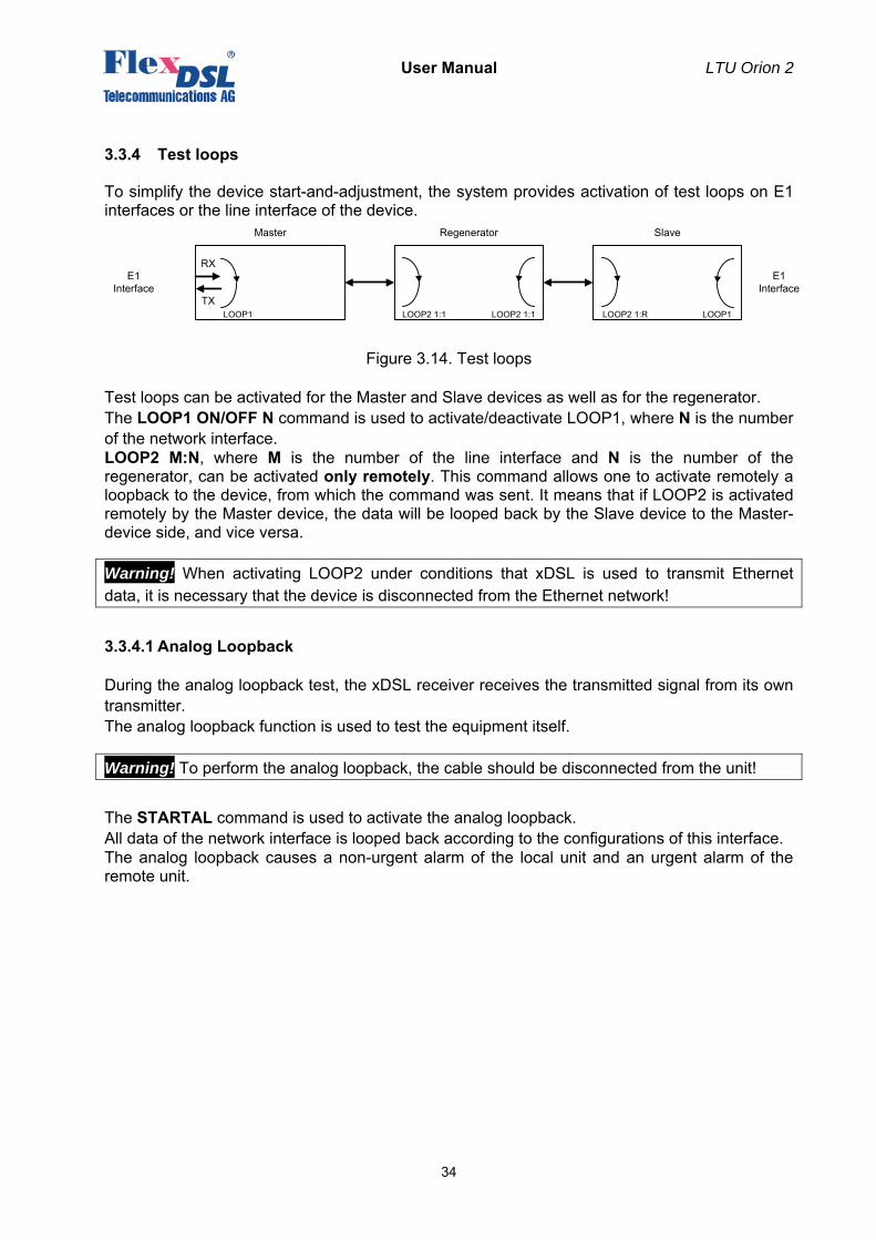
3.3.4 Test loops
To simplify the device start-and-adjustment, the system provides activation of test loops on E1 interfaces or the line interface of the device.
Figure 3.14. Test loops
Test loops can be activated for the Master and Slave devices as well as for the regenerator. The LOOP1 ON/OFF N command is used to activate/deactivate LOOP1, where N is the number of the network interface. LOOP2 M:N, where M is the number of the line interface and N is the number of the regenerator, can be activated only remotely. This command allows one to activate remotely a loopback to the device, from which the command was sent. It means that if LOOP2 is activated remotely by the Master device, the data will be looped back by the Slave device to the Master-device side, and vice versa.
Warning! When activating LOOP2 under conditions that xDSL is used to transmit Ethernet data, it is necessary that the device is disconnected from the Ethernet network!
3.3.4.1 Analog Loopback
During the analog loopback test, the xDSL receiver receives the transmitted signal from its own transmitter. The analog loopback function is used to test the equipment itself.
Warning! To perform the analog loopback, the cable should be disconnected from the unit!
The STARTAL command is used to activate the analog loopback. All data of the network interface is looped back according to the configurations of this interface. The analog loopback causes a non-urgent alarm of the local unit and an urgent alarm of the remote unit.
Master Regenerator Slave
E1Interface
E1Interface
RX
TXLOOP1 LOOP1LOOP2 1:R LOOP2 1:1 LOOP2 1:1
User Manual LTU Orion 2
35
3.3.4.2 Performance monitoring
The transmission performance of a link can be monitored in two different ways. The signal quality is typically used during installation and maintenance procedures, whereas the G.826 error performance parameters are used for long term evaluation of operating links and during acceptance testing. The Noise Margin (NM) provides qualitative performance information of a specific link. The NM command is used to activate this test. This parameter is calculated according to G.991.2 and is an efficient tool for determining the qualitative performance of an xDSL link. During acceptance testing, it is recommended to set the line rate or choose cable pairs (at a fixed line rate) so that the NM value be no less that 6 dB. An NM of 0dB in the presence of a Gaussian noise would yield an expected Bit-Error-Ratio of 10-7.
3.3.4.3 G.826 performance monitoring
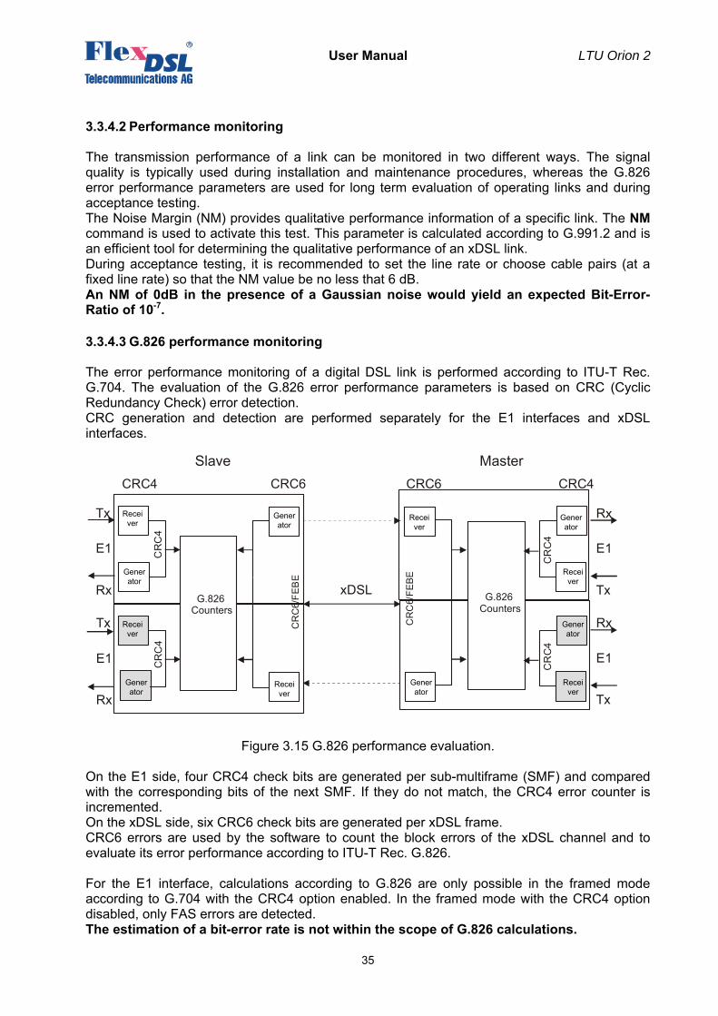
The error performance monitoring of a digital DSL link is performed according to ITU-T Rec. G.704. The evaluation of the G.826 error performance parameters is based on CRC (Cyclic Redundancy Check) error detection. CRC generation and detection are performed separately for the E1 interfaces and xDSL interfaces.
Figure 3.15 G.826 performance evaluation. On the E1 side, four CRC4 check bits are generated per sub-multiframe (SMF) and compared with the corresponding bits of the next SMF. If they do not match, the CRC4 error counter is incremented. On the xDSL side, six CRC6 check bits are generated per xDSL frame. CRC6 errors are used by the software to count the block errors of the xDSL channel and to evaluate its error performance according to ITU-T Rec. G.826. For the E1 interface, calculations according to G.826 are only possible in the framed mode according to G.704 with the CRC4 option enabled. In the framed mode with the CRC4 option disabled, only FAS errors are detected. The estimation of a bit-error rate is not within the scope of G.826 calculations.
G.826Counters
xDSL
CRC6CRC4 CRC4CRC6
Slave Master
C
RC
4
C
RC
4
CR
C6/
FEB
E
Tx
E1
RxTx
E1
Rx
C
RC
4
Tx
E1
Rx
C
RC
4
CR
C6/
FEBE
Tx
E1
Rx
G.826Counters
Receiver
Generator
Receiver
Generator
Receiver
Generator
Receiver
Generator
Generator
Generator
Receiver
Receiver
User Manual LTU Orion 2
36
The G826 and G826 E1 command (the Performance management menu) are used to view the G.826 error performance statistics.
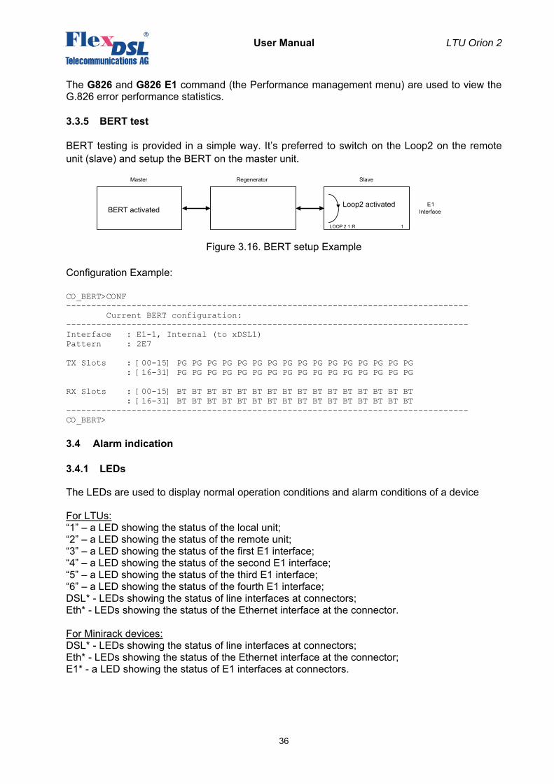
3.3.5 BERT test
BERT testing is provided in a simple way. It’s preferred to switch on the Loop2 on the remote unit (slave) and setup the BERT on the master unit.
Figure 3.16. BERT setup Example Configuration Example: CO_BERT>CONF -------------------------------------------------------------------------------- Current BERT configuration: -------------------------------------------------------------------------------- Interface : E1-1, Internal (to xDSL1) Pattern : 2E7 TX Slots : [00-15] PG PG PG PG PG PG PG PG PG PG PG PG PG PG PG PG : [16-31] PG PG PG PG PG PG PG PG PG PG PG PG PG PG PG PG RX Slots : [00-15] BT BT BT BT BT BT BT BT BT BT BT BT BT BT BT BT : [16-31] BT BT BT BT BT BT BT BT BT BT BT BT BT BT BT BT -------------------------------------------------------------------------------- CO_BERT>
3.4 Alarm indication
3.4.1 LEDs
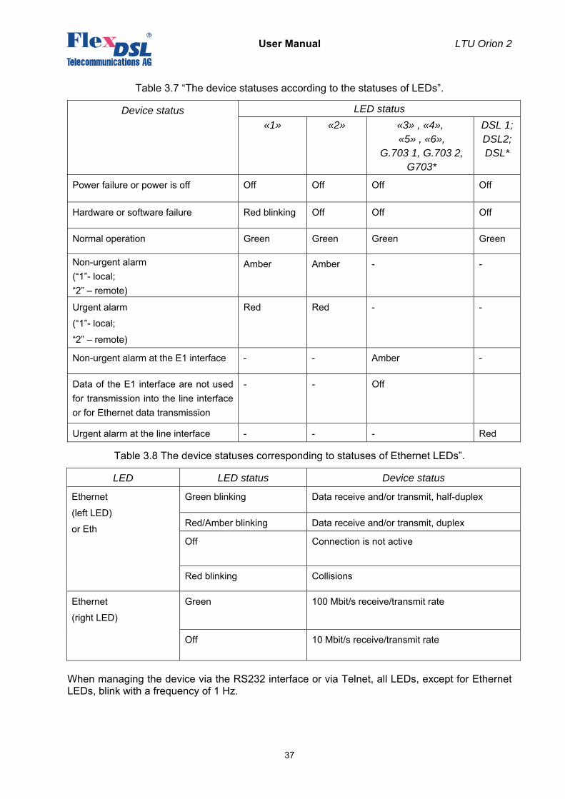
The LEDs are used to display normal operation conditions and alarm conditions of a device For LTUs: “1” – a LED showing the status of the local unit; “2” – a LED showing the status of the remote unit; “3” – a LED showing the status of the first E1 interface; “4” – a LED showing the status of the second E1 interface; “5” – a LED showing the status of the third E1 interface; “6” – a LED showing the status of the fourth E1 interface; DSL* - LEDs showing the status of line interfaces at connectors; Eth* - LEDs showing the status of the Ethernet interface at the connector. For Minirack devices: DSL* - LEDs showing the status of line interfaces at connectors; Eth* - LEDs showing the status of the Ethernet interface at the connector; E1* - a LED showing the status of E1 interfaces at connectors.
Master Regenerator Slave
E 1Interface
1LOOP 2 1:R
BERT activatedLoop2 activated
User Manual LTU Orion 2
37
Table 3.7 “The device statuses according to the statuses of LEDs”.
Device status LED status «1» «2» «3» , «4»,
«5» , «6», G.703 1, G.703 2,
G703*
DSL 1; DSL2; DSL*
Power failure or power is off Off Off Off Off
Hardware or software failure Red blinking Off Off Off
Normal operation Green Green Green Green
Non-urgent alarm (“1”- local; “2” – remote)
Amber Amber - -
Urgent alarm
(“1”- local;
“2” – remote)
Red Red - -
Non-urgent alarm at the E1 interface - - Amber -
Data of the E1 interface are not used for transmission into the line interface or for Ethernet data transmission
- - Off
Urgent alarm at the line interface - - - Red
Table 3.8 The device statuses corresponding to statuses of Ethernet LEDs”.
LED LED status Device status
Ethernet
(left LED)
or Eth
Green blinking Data receive and/or transmit, half-duplex
Red/Amber blinking Data receive and/or transmit, duplex
Off Connection is not active
Red blinking Collisions
Ethernet
(right LED)
Green 100 Mbit/s receive/transmit rate
Off 10 Mbit/s receive/transmit rate
When managing the device via the RS232 interface or via Telnet, all LEDs, except for Ethernet LEDs, blink with a frequency of 1 Hz.
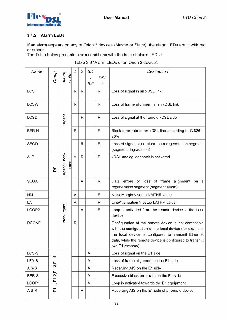
User Manual LTU Orion 2
38
3.4.2 Alarm LEDs
If an alarm appears on any of Orion 2 devices (Master or Slave), the alarm LEDs are lit with red or amber. The Table below presents alarm conditions with the help of alarm LEDs.:
Table 3.9 “Alarm LEDs of an Orion 2 device”.
Name
Gro
up
Ala
rm
stat
us 1 2 3,4
, 5,6
DSL
*
Description
LOS
DS
L
Urg
ent
R
R
R Loss of signal in an xDSL link
LOSW R
R Loss of frame alignment in an xDSL link
LOSD R
R Loss of signal at the remote xDSL side
BER-H R
R Block-error-rate in an xDSL line according to G.826 ≥ 30%
SEGD R
R Loss of signal or an alarm on a regeneration segment (segment degradation)
ALB
Urg
ent +
non
-ur
gent
A R
R xDSL analog loopback is activated
SEGA
Non
-urg
ent
A R Data errors or loss of frame alignment on a regeneration segment (segment alarm)
NM A R NoiseMargin < setup NMTHR value
LA A R LineAttenuation > setup LATHR value
LOOP2 A R Loop is activated from the remote device to the local device
RCONF R
Configuration of the remote device is not compatible with the configuration of the local device (for example, the local device is configured to transmit Ethernet data, while the remote device is configured to transmit two E1 streams)
LOS-S
E1-
1, E
1-2,
E1-3
,E1-
4
A Loss of signal on the Е1 side
LFA-S A Loss of frame alignment on the E1 side
AIS-S A Receiving AIS on the E1 side
BER-S A Excessive block error rate on the Е1 side
LOOP1 A Loop is activated towards the Е1 equipment
AIS-R A Receiving AIS on the E1 side of a remote device

User Manual LTU Orion 2
39
HW-F
Mai
nten
ance
RB
Hardware failure
DSL-F RB
DSL signal processor initialization failure
“A” – amber LED “R” – red LED “RB” – red LED blinking Displaying an urgent alarm has the highest priority that displaying a non-urgent alarm.
User Manual LTU Orion 2
40
3.5 Management of FlexDSL Orion 2 devices
The equipment has integrated functions of management and diagnostics. FlexDSL Orion 2 devices can be connected to the terminal by using the RS232 interface or to a PC with the VT100 terminal. In addition, devices can be connected to a PC network card or the Ethernet network, to which the computer is attached. In this case, the Telnet session is used to manage the equipment, the WEB interface being used to display the statistics. The management and diagnostics functions allow one to configure devices and to receive additional information, such as parameters of an xDSL link quality or G.826.
3.5.1 Management of FlexDSL Orion 2 with the RS232 interface
The rear panel of the FlexGain shelf contains the TTL management bus which is organized according to the “point / multipoint” scheme. The TTL-RS232 converter and a terminal connector are on the rear panel of the shelf. If the ACU / TCU unit is used, the management connector is on the front panel of this device. At any one time only one device in the shelf can be logically connected to the management interface. The device is chosen in accordance with the slot number, in which it is mounted. To select the necessary device, input <%SN↵>, where SN is the slot number. Example: to select the unit, mounted in slot 3, type: %03↵. The unit in the shelf displays %SN after the ECHO command is entered, where SN is the slot number. After typing “ECHO”, the operator will receive a response from LTU devices, as it is shown below: ECHO↵ 01 02 08 10 11 12
3.5.2 Management of FlexDSL Orion 2 devices with Ethernet interfaces
3.5.2.1 Telnet
The front panel of FlexDSL Orion 2 devices contains the Ethernet connector. The local network containing the management computer (or the PC itself) can be connected to this connector. Management is performed by using the Telnet session activated by a standard command: telnet <IP-address> in Windows 95 or above. (Any other program can be used to open the Telnet session if it supports this protocol.) The TELNET session is used to configure modems remotely as well as other devices connected to the MONITOR bus of the same FlexGain shelf to which the modem is connected. After opening the TELNET session, the user authentication is performed. Two types of users are used: “admin” users, who can change configurations and “user” users who can only view parameters and statistics. Initially passwords are empty; authentication in this case is not performed and users automatically have the administrator rights. Only “admin” users can set passwords for both types of users. If authentication is successful, the modem main menu is displayed. If authentication fails, it is repeated up to three times, and after it the connection breaks. For SubRack devices at any time except for the moment when the password is entered in the Telnet session, the command for choosing devices to manage %NNN is available (NNN are digits and symbols of the Latin alphabet in the range from 0 to 80). This command is used to
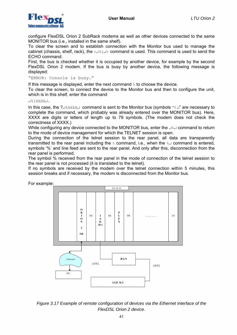
User Manual LTU Orion 2
41
configure FlexDSL Orion 2 SubRack modems as well as other devices connected to the same MONITOR bus (i.e., installed in the same shelf). To clear the screen and to establish connection with the Monitor bus used to manage the cabinet (chassis, shelf, rack), the <↵%1↵> command is used. This command is used to send the ECHO command. First, the bus is checked whether it is occupied by another device, for example by the second FlexDSL Orion 2 modem. If the bus is busy by another device, the following message is displayed: “ERROR: Console is busy.”
If this message is displayed, enter the next command % to choose the device. To clear the screen, to connect the device to the Monitor bus and then to configure the unit, which is in this shelf, enter the command ↵%1XXXX↵.
In this case, the ?↵%XXXX↵ command is sent to the Monitor bus (symbols “?↵” are necessary to complete the command, which probably was already entered over the MONITOR bus). Here, XXXX are digits or letters of length up to 79 symbols. (The modem does not check the correctness of XXXX.) While configuring any device connected to the MONITOR bus, enter the ↵%↵ command to return to the mode of device management for which the TELNET session is open. During the connection of the telnet session to the rear panel, all data are transparently transmitted to the rear panel including the % command, i.e., when the %↵ command is entered, symbols ‘%’ and line feed are sent to the rear panel. And only after this, disconnection from the rear panel is performed. The symbol % received from the rear panel in the mode of connection of the telnet session to the rear panel is not processed (it is translated to the telnet). If no symbols are received by the modem over the telnet connection within 5 minutes, this session breaks and if necessary, the modem is disconnected from the Monitor bus. For example:
Figure 3.17 Example of remote configuration of devices via the Ethernet interface of the FlexDSL Orion 2 device.
04
O R I O N
2
SR
04
I A D № 1
P L E X
06
08
14
… … … ..
FG -R -W
R G N
IA D № 2
xD SL xD SL
PC
Ethernet
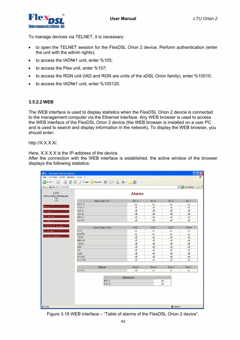
User Manual LTU Orion 2
42
To manage devices via TELNET, it is necessary: • to open the TELNET session for the FlexDSL Orion 2 device. Perform authentication (enter
the unit with the admin rights);
• to access the IAD№1 unit, enter %105;
• to access the Plex unit, enter %107;
• to access the RGN unit (IAD and RGN are units of the xDSL Orion family), enter %10510;
• to access the IAD№1 unit, enter %105120.
3.5.2.2 WEB
The WEB interface is used to display statistics when the FlexDSL Orion 2 device is connected to the management computer via the Ethernet interface. Any WEB browser is used to access the WEB interface of the FlexDSL Orion 2 device (the WEB browser is installed on a user PC and is used to search and display information in the network). To display the WEB browser, you should enter: http://X.X.X.X/. Here, X.X.X.X is the IP-address of the device. After the connection with the WEB interface is established, the active window of the browser displays the following statistics:
Figure 3.18 WEB interface – “Table of alarms of the FlexDSL Orion 2 device”.
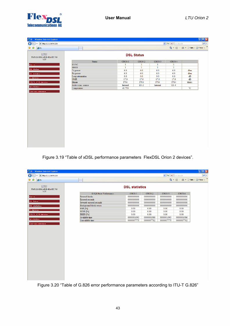
User Manual LTU Orion 2
43
Figure 3.19 “Table of xDSL performance parameters FlexDSL Orion 2 devices”.
Figure 3.20 “Table of G.826 error performance parameters according to ITU-T G.826”
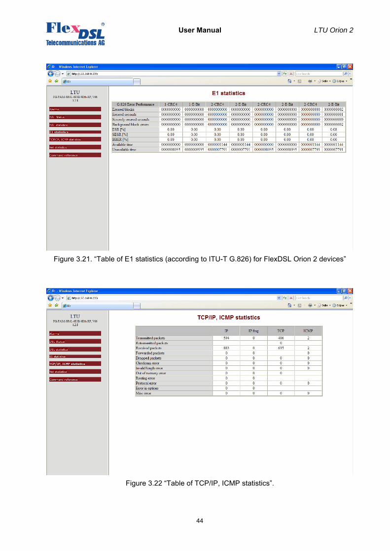
User Manual LTU Orion 2
44
Figure 3.21. “Table of E1 statistics (according to ITU-T G.826) for FlexDSL Orion 2 devices”
Figure 3.22 “Table of TCP/IP, ICMP statistics”.
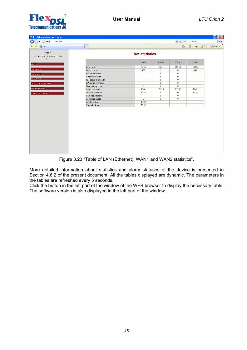
User Manual LTU Orion 2
45
Figure 3.23 “Table of LAN (Ethernet), WAN1 and WAN2 statistics”. More detailed information about statistics and alarm statuses of the device is presented in Section 4.6.2 of the present document. All the tables displayed are dynamic. The parameters in the tables are refreshed every 5 seconds. Click the button in the left part of the window of the WEB browser to display the necessary table. The software version is also displayed in the left part of the window.
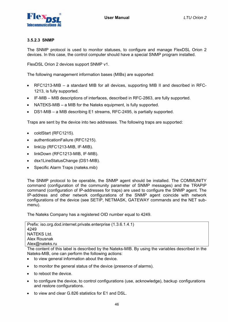
User Manual LTU Orion 2
46
3.5.2.3 SNMP
The SNMP protocol is used to monitor statuses, to configure and manage FlexDSL Orion 2 devices. In this case, the control computer should have a special SNMP program installed. FlexDSL Orion 2 devices support SNMP v1.
The following management information bases (MIBs) are supported:
• RFC1213-MIB – a standard MIB for all devices, supporting MIB II and described in RFC- 1213, is fully supported.
• IF-MIB – MIB descriptions of interfaces, described in RFC-2863, are fully supported. • NATEKS-MIB – a MIB for the Nateks equipment, is fully supported. • DS1-MIB – a MIB describing E1 streams, RFC-2495, is partially supported.
Traps are sent by the device into two addresses. The following traps are supported:
• coldStart (RFC1215). • authenticationFailure (RFC1215). • linkUp (RFC1213-MIB, IF-MIB). • linkDown (RFC1213-MIB, IF-MIB). • dsx1LineStatusChange (DS1-MIB). • Specific Alarm Traps (nateks.mib) The SNMP protocol to be operable, the SNMP agent should be installed. The COMMUNITY command (configuration of the community parameter of SNMP messages) and the TRAPIP command (configuration of IP-addresses for traps) are used to configure the SNMP agent. The IP-address and other network configurations of the SNMP agent coincide with network configurations of the device (see SETIP, NETMASK, GATEWAY commands and the NET sub-menu). The Nateks Company has a registered OID number equal to 4249. Prefix: iso.org.dod.internet.private.enterprise (1.3.6.1.4.1) 4249 NATEKS Ltd. Alex Rousnak [email protected] The content of this label is described by the Nateks-MIB. By using the variables described in the Nateks-MIB, one can perform the following actions: • to view general information about the device.
• to monitor the general status of the device (presence of alarms).
• to reboot the device.
• to configure the device, to control configurations (use, acknowledge), backup configurations and restore configurations.
• to view and clear G.826 statistics for E1 and DSL.
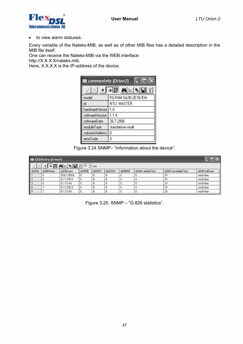
User Manual LTU Orion 2
47
• to view alarm statuses.
Every variable of the Nateks-MIB, as well as of other MIB files has a detailed description in the MIB file itself. One can receive the Nateks-MIB via the WEB interface: http://X.X.X.X/nateks.mib. Here, X.X.X.X is the IP-address of the device.
Figure 3.24 SNMP– “Information about the device”.
Figure 3.25. SNMP – “G.826 statistics”.
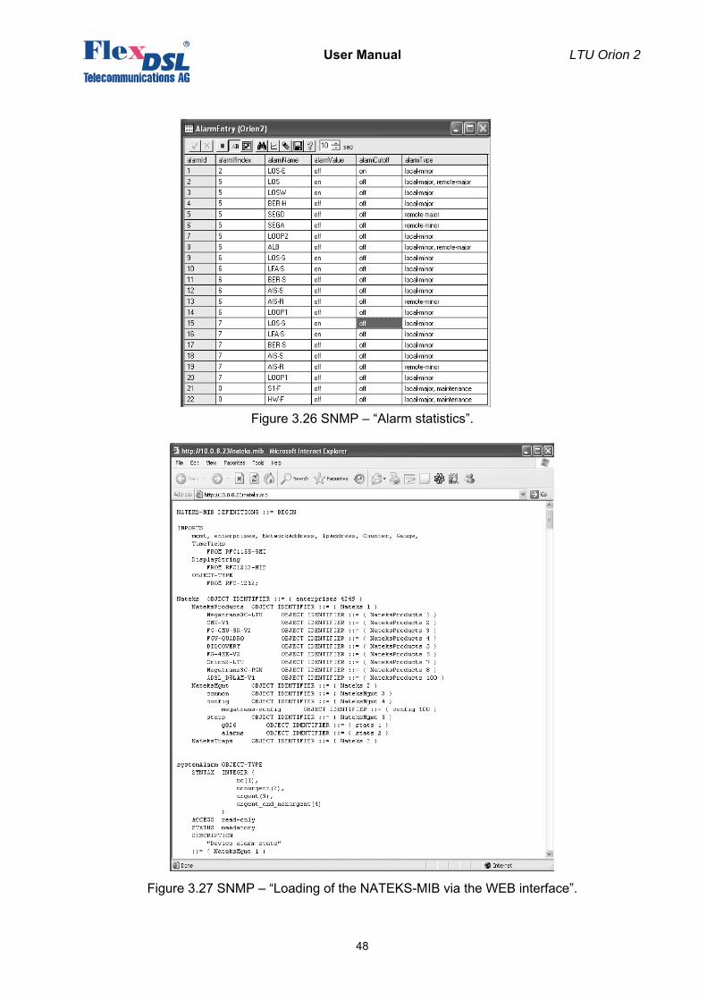
User Manual LTU Orion 2
48
Figure 3.26 SNMP – “Alarm statistics”.
Figure 3.27 SNMP – “Loading of the NATEKS-MIB via the WEB interface”.
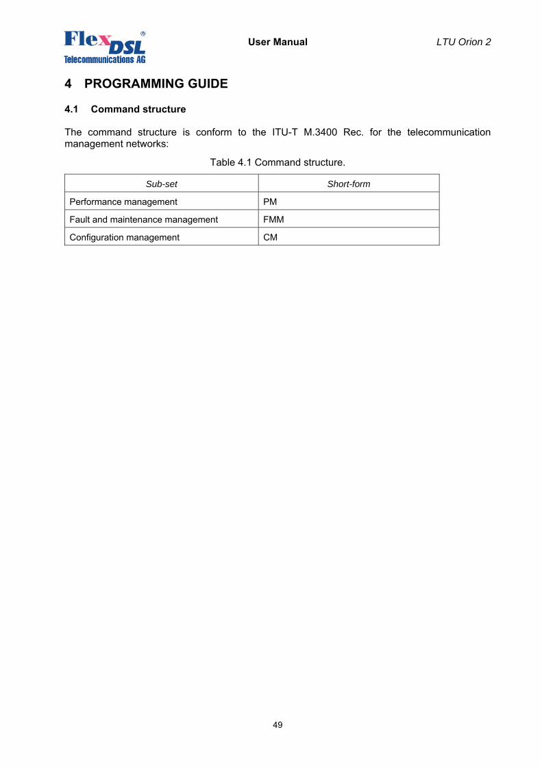
User Manual LTU Orion 2
49
4 PROGRAMMING GUIDE
4.1 Command structure
The command structure is conform to the ITU-T M.3400 Rec. for the telecommunication management networks:
Table 4.1 Command structure.
Sub-set Short-form
Performance management PM
Fault and maintenance management FMM
Configuration management CM
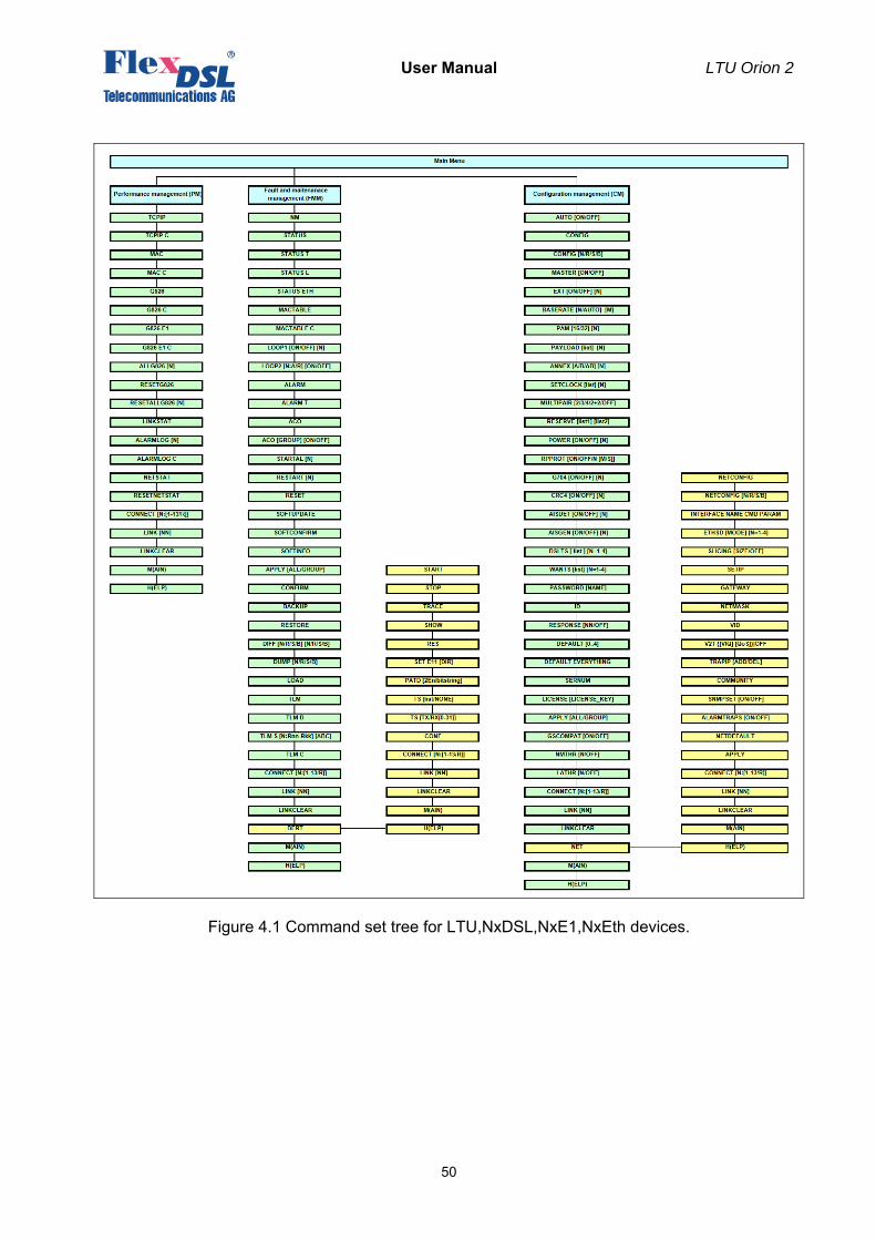
User Manual LTU Orion 2
50
Figure 4.1 Command set tree for LTU,NxDSL,NxE1,NxEth devices.
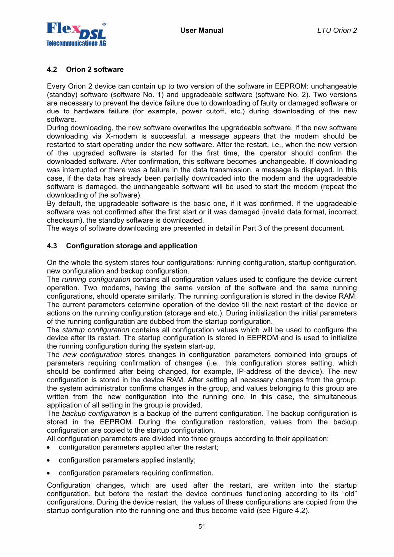
User Manual LTU Orion 2
51
4.2 Orion 2 software
Every Orion 2 device can contain up to two version of the software in EEPROM: unchangeable (standby) software (software No. 1) and upgradeable software (software No. 2). Two versions are necessary to prevent the device failure due to downloading of faulty or damaged software or due to hardware failure (for example, power cutoff, etc.) during downloading of the new software. During downloading, the new software overwrites the upgradeable software. If the new software downloading via X-modem is successful, a message appears that the modem should be restarted to start operating under the new software. After the restart, i.e., when the new version of the upgraded software is started for the first time, the operator should confirm the downloaded software. After confirmation, this software becomes unchangeable. If downloading was interrupted or there was a failure in the data transmission, a message is displayed. In this case, if the data has already been partially downloaded into the modem and the upgradeable software is damaged, the unchangeable software will be used to start the modem (repeat the downloading of the software). By default, the upgradeable software is the basic one, if it was confirmed. If the upgradeable software was not confirmed after the first start or it was damaged (invalid data format, incorrect checksum), the standby software is downloaded. The ways of software downloading are presented in detail in Part 3 of the present document.
4.3 Configuration storage and application
On the whole the system stores four configurations: running configuration, startup configuration, new configuration and backup configuration. The running configuration contains all configuration values used to configure the device current operation. Two modems, having the same version of the software and the same running configurations, should operate similarly. The running configuration is stored in the device RAM. The current parameters determine operation of the device till the next restart of the device or actions on the running configuration (storage and etc.). During initialization the initial parameters of the running configuration are dubbed from the startup configuration. The startup configuration contains all configuration values which will be used to configure the device after its restart. The startup configuration is stored in EEPROM and is used to initialize the running configuration during the system start-up. The new configuration stores changes in configuration parameters combined into groups of parameters requiring confirmation of changes (i.e., this configuration stores setting, which should be confirmed after being changed, for example, IP-address of the device). The new configuration is stored in the device RAM. After setting all necessary changes from the group, the system administrator confirms changes in the group, and values belonging to this group are written from the new configuration into the running one. In this case, the simultaneous application of all setting in the group is provided. The backup configuration is a backup of the current configuration. The backup configuration is stored in the EEPROM. During the configuration restoration, values from the backup configuration are copied to the startup configuration. All configuration parameters are divided into three groups according to their application: • configuration parameters applied after the restart;
• configuration parameters applied instantly;
• configuration parameters requiring confirmation.
Configuration changes, which are used after the restart, are written into the startup configuration, but before the restart the device continues functioning according to its “old” configurations. During the device restart, the values of these configurations are copied from the startup configuration into the running one and thus become valid (see Figure 4.2).
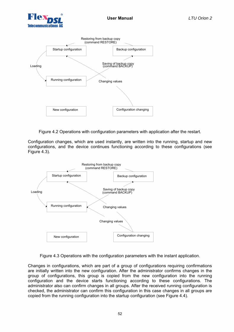
User Manual LTU Orion 2
52
Figure 4.2 Operations with configuration parameters with application after the restart.
Configuration changes, which are used instantly, are written into the running, startup and new configurations, and the device continues functioning according to these configurations (see Figure 4.3).
Figure 4.3 Operations with the configuration parameters with the instant application. Changes in configurations, which are part of a group of configurations requiring confirmations are initially written into the new configuration. After the administrator confirms changes in the group of configurations, this group is copied from the new configuration into the running configuration and the device starts functioning according to these configurations. The administrator also can confirm changes in all groups. After the received running configuration is checked, the administrator can confirm this configuration in this case changes in all groups are copied from the running configuration into the startup configuration (see Figure 4.4).
Startup configuration Backup configuration
Running configuration
New configuration
Loading Saving of backup copy(command BACKUP)
Changing values
Configuration changing
Changing values
Restoring from backup copy(command RESTORE)
Startup configuration Backup configuration
Running configuration
New configuration
Loading Saving of backup copy(command BACKUP)
Configuration changing
Changing values
Restoring from backup copy(command RESTORE)
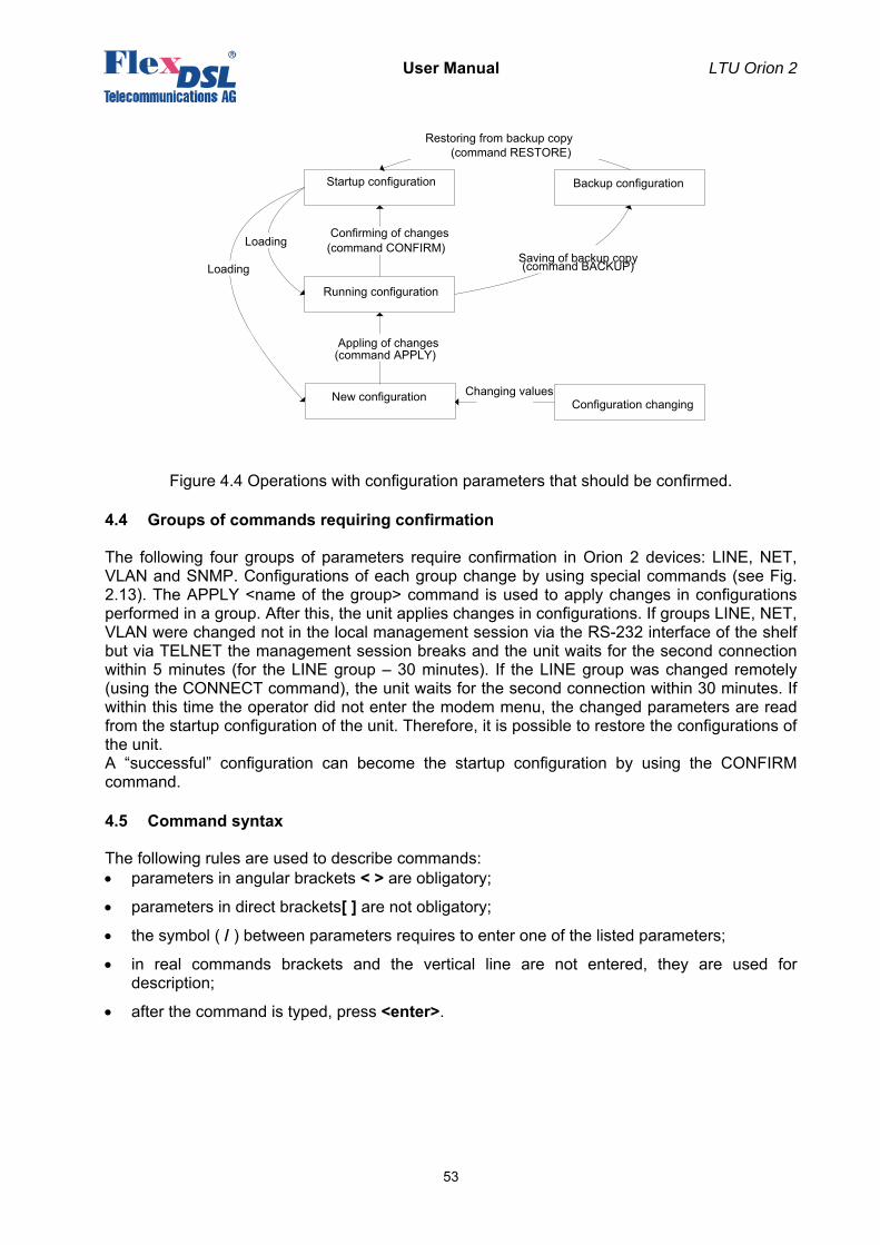
User Manual LTU Orion 2
53
Figure 4.4 Operations with configuration parameters that should be confirmed.
4.4 Groups of commands requiring confirmation
The following four groups of parameters require confirmation in Orion 2 devices: LINE, NET, VLAN and SNMP. Configurations of each group change by using special commands (see Fig. 2.13). The APPLY <name of the group> command is used to apply changes in configurations performed in a group. After this, the unit applies changes in configurations. If groups LINE, NET, VLAN were changed not in the local management session via the RS-232 interface of the shelf but via TELNET the management session breaks and the unit waits for the second connection within 5 minutes (for the LINE group – 30 minutes). If the LINE group was changed remotely (using the CONNECT command), the unit waits for the second connection within 30 minutes. If within this time the operator did not enter the modem menu, the changed parameters are read from the startup configuration of the unit. Therefore, it is possible to restore the configurations of the unit. A “successful” configuration can become the startup configuration by using the CONFIRM command.
4.5 Command syntax
The following rules are used to describe commands: • parameters in angular brackets < > are obligatory;
• parameters in direct brackets[ ] are not obligatory;
• the symbol ( / ) between parameters requires to enter one of the listed parameters;
• in real commands brackets and the vertical line are not entered, they are used for description;
• after the command is typed, press <enter>.
Startup configuration Backup configuration
Running configuration
New configuration
Appling of changes(command APPLY)
Confirming of changes(command CONFIRM)Loading
Loading
Saving of backup copy (command BACKUP)
Changing values Configuration changing
Restoring from backup copy (command RESTORE)
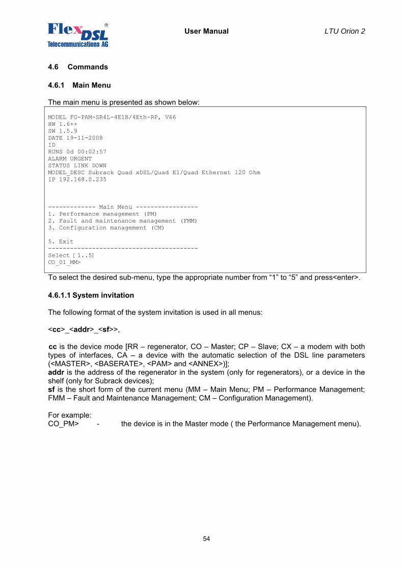
User Manual LTU Orion 2
54
4.6 Commands
4.6.1 Main Menu
The main menu is presented as shown below: MODEL FG-PAM-SR4L-4E1B/4Eth-RP, V66 HW 1.6++ SW 1.5.9 DATE 19-11-2008 ID RUNS 0d 00:02:57 ALARM URGENT STATUS LINK DOWN MODEL_DESC Subrack Quad xDSL/Quad E1/Quad Ethernet 120 Ohm IP 192.168.0.235 ------------- Main Menu ----------------- 1. Performance management (PM) 2. Fault and maintenance management (FMM) 3. Configuration management (CM) 5. Exit ----------------------------------------- Select [1..5] CO_01_MM>
To select the desired sub-menu, type the appropriate number from “1” to “5” and press<enter>.
4.6.1.1 System invitation
The following format of the system invitation is used in all menus: <cc>_<addr>_<sf>>, сс is the device mode [RR – regenerator, CO – Master; CP – Slave; CX – a modem with both types of interfaces, CA – a device with the automatic selection of the DSL line parameters (<MASTER>, <BASERATE>, <PAM> and <ANNEX>)]; addr is the address of the regenerator in the system (only for regenerators), or a device in the shelf (only for Subrack devices); sf is the short form of the current menu (MM – Main Menu; PM – Performance Management; FMM – Fault and Maintenance Management; CM – Configuration Management). For example: CO_PM> - the device is in the Master mode ( the Performance Management menu).
User Manual LTU Orion 2
55
4.6.2 General Commands
4.6.2.1 <H> command
After the <H> command is entered the device displays the help menu.
4.6.2.2 <CONNECT N:1..13/R> command
The <CONNECT N:1..13/R> commands initializes the management of the remote device. The parameter N sets the number of the xDSL channel, over which the connection is initialized. In single-channel systems the parameter N can be absent. Notes:
1. The <CONNECT R> command in the Slave mode is only available if the Master device can be configured locally at this instant.
2. The <CONNECT N> (N=1..13) command initializes the management of the remote regenerator. The <CONNECT N> command is available only in the Master mode.
3. This command is not provisioned for regenerators. 4. If the channel of remote management is blocked (for example, a message or a table are
not displayed completely), press Enter.
4.6.2.3 <LINK [SN/00/FE]> > command
The < LINK [SN/00/FE]> command establishes connection to specified unit over the backplane.
• SN - Specifies slot number of a subrack unit in cassette to establish connect with. If backplane is busy "LINK ERROR" message will be issued by unit. If specified cassette slot is free (or no response in 1.5 first seconds) the same message will be issued. For subrack units SN should not be 00.
• 00 - (double zero) Switches on Monitor connector control mode for Minirack and standalone
units. In this mode all typed characters will be translated to Monitor connector. • FE - (for ever) Switches on Monitor connector control mode for common CLI RS232 units.
In this mode all typed characters will be translated to Monitor connector. The connection will be established until a terminal timeout appears.
Example: • LINK 10 - Establish connection to subrack unit with slot number 10. Available only for
subrack units. • LINK 00 - Establish monitor control node. Available only for subrack units. • LINK FE - Establish monitor control node. Available only for common CLI RS232 Terminal
units. Notes: To refuse link connection just exit from controllable unit. To refuse link connection urgently use CTRL+Z keystroke.
4.6.2.4 <LINKCLEAR> command
The < LINKCLEAR > command closes current virtual link connections.
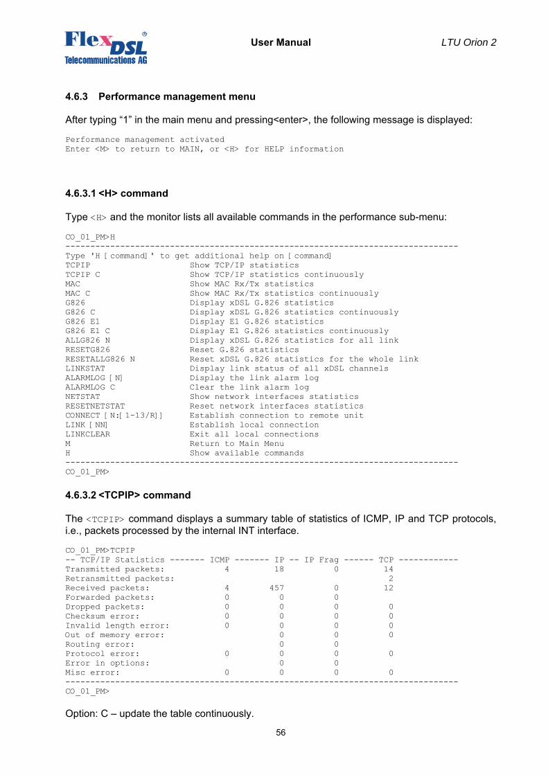
User Manual LTU Orion 2
56
4.6.3 Performance management menu
After typing “1” in the main menu and pressing<enter>, the following message is displayed: Performance management activated Enter <M> to return to MAIN, or <H> for HELP information
4.6.3.1 <H> command
Type <H> and the monitor lists all available commands in the performance sub-menu: CO_01_PM>H ------------------------------------------------------------------------------- Type 'H [command]' to get additional help on [command] TCPIP Show TCP/IP statistics TCPIP C Show TCP/IP statistics continuously MAC Show MAC Rx/Tx statistics MAC C Show MAC Rx/Tx statistics continuously G826 Display xDSL G.826 statistics G826 C Display xDSL G.826 statistics continuously G826 E1 Display E1 G.826 statistics G826 E1 C Display E1 G.826 statistics continuously ALLG826 N Display xDSL G.826 statistics for all link RESETG826 Reset G.826 statistics RESETALLG826 N Reset xDSL G.826 statistics for the whole link LINKSTAT Display link status of all xDSL channels ALARMLOG [N] Display the link alarm log ALARMLOG C Clear the link alarm log NETSTAT Show network interfaces statistics RESETNETSTAT Reset network interfaces statistics CONNECT [N:[1-13/R]] Establish connection to remote unit LINK [NN] Establish local connection LINKCLEAR Exit all local connections M Return to Main Menu H Show available commands ------------------------------------------------------------------------------- CO_01_PM>
4.6.3.2 <TCPIP> command
The <TCPIP> command displays a summary table of statistics of ICMP, IP and TCP protocols, i.e., packets processed by the internal INT interface. CO_01_PM>TCPIP -- TCP/IP Statistics ------- ICMP ------- IP -- IP Frag ------ TCP ------------ Transmitted packets: 4 18 0 14 Retransmitted packets: 2 Received packets: 4 457 0 12 Forwarded packets: 0 0 0 Dropped packets: 0 0 0 0 Checksum error: 0 0 0 0 Invalid length error: 0 0 0 0 Out of memory error: 0 0 0 Routing error: 0 0 Protocol error: 0 0 0 0 Error in options: 0 0 Misc error: 0 0 0 0 ------------------------------------------------------------------------------- CO_01_PM> Option: С – update the table continuously.
User Manual LTU Orion 2
57
The column ICMP shows the ICMP operation, the column IP shows statistics of the IP protocol, the column IP frag displays the operation with fragmented IP packets and the column TCP displays the statistics of the TCP protocol. Transmitted packets – the number of transmitted packets. Retransmitted packets – the number of retransmitted packets. Not applied to IP and IP Frag. Received packets – the number of received packets. Forwarded packets – the number of forwarded packets. Not applied to TCP. Dropped packets – the number of dropped packets. Checksum error – the number of packets with the checksum error. Invalid length error – the number of packets with an invalid length error. Out of memory error – the number of packets out of memory of the device TCP/IP stack. Routing error – the number of routing errors when transmitting packets. Protocol error – the number of packets with protocol errors and with limitations imposed by the protocol. Error in options – the number of IP packets with the invalid field “options”. Misc error – the number of other errors. Note: The system does not calculate statistics over all ICMP packets passing through network
interfaces of the modem. Calculation is performed only over packets forwarded to the internal network interface of the modem: broadcast and multicast packets, and packets used in telnet, SNMP, WEB.
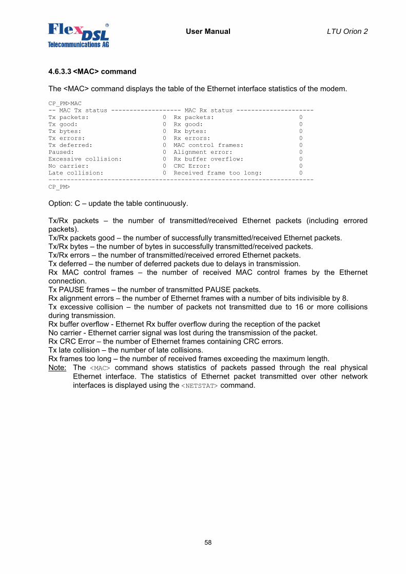
User Manual LTU Orion 2
58
4.6.3.3 <MAC> command
The <MAC> command displays the table of the Ethernet interface statistics of the modem. CP_PM>MAC -- MAC Tx status ------------------- MAC Rx status --------------------- Tx packets: 0 Rx packets: 0 Tx good: 0 Rx good: 0 Tx bytes: 0 Rx bytes: 0 Tx errors: 0 Rx errors: 0 Tx deferred: 0 MAC control frames: 0 Paused: 0 Alignment error: 0 Excessive collision: 0 Rx buffer overflow: 0 No carrier: 0 CRC Error: 0 Late collision: 0 Received frame too long: 0 ------------------------------------------------------------------------ CP_PM> Option: С – update the table continuously. Tx/Rx packets – the number of transmitted/received Ethernet packets (including errored packets). Tx/Rx packets good – the number of successfully transmitted/received Ethernet packets. Tx/Rx bytes – the number of bytes in successfully transmitted/received packets. Tx/Rx errors – the number of transmitted/received errored Ethernet packets. Tx deferred – the number of deferred packets due to delays in transmission. Rx MAC control frames – the number of received MAC control frames by the Ethernet connection. Tx PAUSE frames – the number of transmitted PAUSE packets. Rx alignment errors – the number of Ethernet frames with a number of bits indivisible by 8. Tx excessive collision – the number of packets not transmitted due to 16 or more collisions during transmission. Rx buffer overflow - Ethernet Rx buffer overflow during the reception of the packet No carrier - Ethernet carrier signal was lost during the transmission of the packet. Rx CRC Error – the number of Ethernet frames containing CRC errors. Tx late collision – the number of late collisions. Rx frames too long – the number of received frames exceeding the maximum length. Note: The <MAC> command shows statistics of packets passed through the real physical
Ethernet interface. The statistics of Ethernet packet transmitted over other network interfaces is displayed using the <NETSTAT> command.
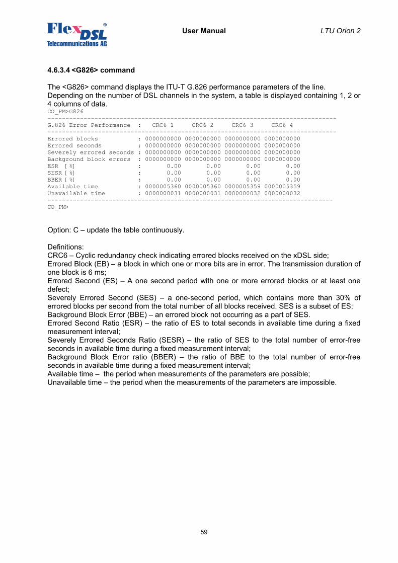
User Manual LTU Orion 2
59
4.6.3.4 <G826> command
The <G826> command displays the ITU-T G.826 performance parameters of the line. Depending on the number of DSL channels in the system, a table is displayed containing 1, 2 or 4 columns of data. CO_PM>G826 -------------------------------------------------------------------------------- G.826 Error Performance : CRC6 1 CRC6 2 CRC6 3 CRC6 4 -------------------------------------------------------------------------------- Errored blocks : 0000000000 0000000000 0000000000 0000000000 Errored seconds : 0000000000 0000000000 0000000000 0000000000 Severely errored seconds : 0000000000 0000000000 0000000000 0000000000 Background block errors : 0000000000 0000000000 0000000000 0000000000 ESR [%] : 0.00 0.00 0.00 0.00 SESR [%] : 0.00 0.00 0.00 0.00 BBER [%] : 0.00 0.00 0.00 0.00 Available time : 0000005360 0000005360 0000005359 0000005359 Unavailable time : 0000000031 0000000031 0000000032 0000000032 ------------------------------------------------------------------------------- CO_PM> Option: С – update the table continuously. Definitions: CRC6 – Cyclic redundancy check indicating errored blocks received on the xDSL side; Errored Block (EB) – a block in which one or more bits are in error. The transmission duration of one block is 6 ms; Errored Second (ES) – A one second period with one or more errored blocks or at least one defect; Severely Errored Second (SES) – a one-second period, which contains more than 30% of errored blocks per second from the total number of all blocks received. SES is a subset of ES; Background Block Error (BBE) – an errored block not occurring as a part of SES. Errored Second Ratio (ESR) – the ratio of ES to total seconds in available time during a fixed measurement interval; Severely Errored Seconds Ratio (SESR) – the ratio of SES to the total number of error-free seconds in available time during a fixed measurement interval; Background Block Error ratio (BBER) – the ratio of BBE to the total number of error-free seconds in available time during a fixed measurement interval; Available time – the period when measurements of the parameters are possible; Unavailable time – the period when the measurements of the parameters are impossible.
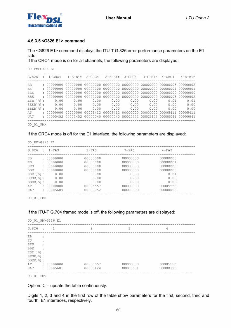
User Manual LTU Orion 2
60
4.6.3.5 <G826 Е1> command
The <G826 Е1> command displays the ITU-T G.826 error performance parameters on the E1 side. If the CRC4 mode is on for all channels, the following parameters are displayed: CO_PM>G826 E1 -------------------------------------------------------------------------------- G.826 : 1-CRC4 1-E-Bit 2-CRC4 2-E-Bit 3-CRC4 3-E-Bit 4-CRC4 4-E-Bit -------------------------------------------------------------------------------- EB : 00000000 00000000 00000000 00000000 00000000 00000000 00000003 00000002 ES : 00000000 00000000 00000000 00000000 00000000 00000000 00000001 00000001 SES : 00000000 00000000 00000000 00000000 00000000 00000000 00000000 00000000 BBE : 00000000 00000000 00000000 00000000 00000000 00000000 00000003 00000002 ESR [%]: 0.00 0.00 0.00 0.00 0.00 0.00 0.01 0.01 SESR[%]: 0.00 0.00 0.00 0.00 0.00 0.00 0.00 0.00 BBER[%]: 0.00 0.00 0.00 0.00 0.00 0.00 0.00 0.00 AT : 00000000 00000000 00005412 00005412 00000000 00000000 00005411 00005411 UAT : 00005452 00005452 00000040 00000040 00005452 00005452 00000041 00000041 -------------------------------------------------------------------------------- CO_01_PM> If the CRC4 mode is off for the E1 interface, the following parameters are displayed: CO_PM>G826 E1 -------------------------------------------------------------------------------- G.826 : 1-FAS 2-FAS 3-FAS 4-FAS -------------------------------------------------------------------------------- EB : 00000000 00000000 00000000 00000003 ES : 00000000 00000000 00000000 00000001 SES : 00000000 00000000 00000000 00000000 BBE : 00000000 00000000 00000000 00000003 ESR [%]: 0.00 0.00 0.00 0.01 SESR[%]: 0.00 0.00 0.00 0.00 BBER[%]: 0.00 0.00 0.00 0.00 AT : 00000000 00005557 00000000 00005556 UAT : 00005609 00000052 00005609 00000053 -------------------------------------------------------------------------------- CO_01_PM>
If the ITU-T G.704 framed mode is off, the following parameters are displayed: CO_01_PM>G826 E1 -------------------------------------------------------------------------------- G.826 : 1 2 3 4 -------------------------------------------------------------------------------- EB : ES : SES : BBE : ESR [%]: SESR[%]: BBER[%]: AT : 00000000 00005557 00000000 00005556 UAT : 00005681 00000124 00005681 00000125 -------------------------------------------------------------------------------- CO_01_PM> Option: С – update the table continuously. Digits 1, 2, 3 and 4 in the first row of the table show parameters for the first, second, third and fourth E1 interfaces, respectively.
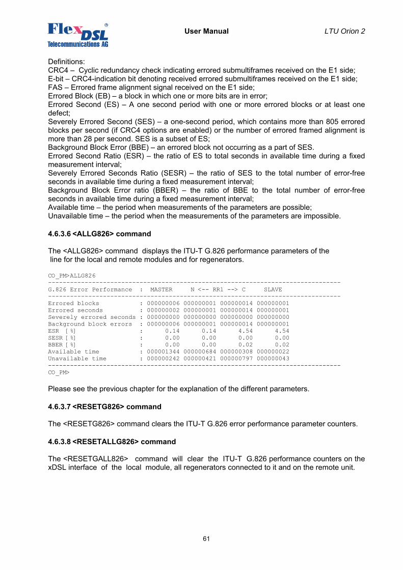
User Manual LTU Orion 2
61
Definitions: CRC4 – Cyclic redundancy check indicating errored submultiframes received on the E1 side; E-bit – CRC4-indication bit denoting received errored submultiframes received on the E1 side; FAS – Errored frame alignment signal received on the E1 side; Errored Block (EB) – a block in which one or more bits are in error; Errored Second (ES) – A one second period with one or more errored blocks or at least one defect; Severely Errored Second (SES) – a one-second period, which contains more than 805 errored blocks per second (if CRC4 options are enabled) or the number of errored framed alignment is more than 28 per second. SES is a subset of ES; Background Block Error (BBE) – an errored block not occurring as a part of SES. Errored Second Ratio (ESR) – the ratio of ES to total seconds in available time during a fixed measurement interval; Severely Errored Seconds Ratio (SESR) – the ratio of SES to the total number of error-free seconds in available time during a fixed measurement interval; Background Block Error ratio (BBER) – the ratio of BBE to the total number of error-free seconds in available time during a fixed measurement interval; Available time – the period when measurements of the parameters are possible; Unavailable time – the period when the measurements of the parameters are impossible.
4.6.3.6 <ALLG826> command
The <ALLG826> command displays the ITU-T G.826 performance parameters of the line for the local and remote modules and for regenerators. CO_PM>ALLG826 -------------------------------------------------------------------------------- G.826 Error Performance : MASTER N <-- RR1 --> C SLAVE -------------------------------------------------------------------------------- Errored blocks : 000000006 000000001 000000014 000000001 Errored seconds : 000000002 000000001 000000014 000000001 Severely errored seconds : 000000000 000000000 000000000 000000000 Background block errors : 000000006 000000001 000000014 000000001 ESR [%] : 0.14 0.14 4.54 4.54 SESR [%] : 0.00 0.00 0.00 0.00 BBER [%] : 0.00 0.00 0.02 0.02 Available time : 000001344 000000684 000000308 000000022 Unavailable time : 000000242 000000421 000000797 000000043 -------------------------------------------------------------------------------- CO_PM> Please see the previous chapter for the explanation of the different parameters.
4.6.3.7 <RESETG826> command
The <RESETG826> command clears the ITU-T G.826 error performance parameter counters.
4.6.3.8 <RESETALLG826> command
The <RESETGALL826> command will clear the ITU-T G.826 performance counters on the xDSL interface of the local module, all regenerators connected to it and on the remote unit.
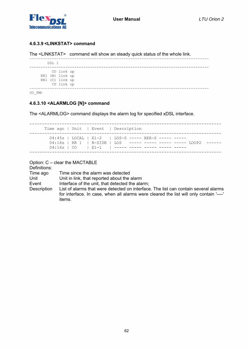
User Manual LTU Orion 2
62
4.6.3.9 <LINKSTAT> command
The <LINKSTAT> command will show an steady quick status of the whole link. -------------------------------------------------------------------------------- DSL 1 -------------------------------------------------------------------------------- CO link up RR1 (N) link up RR1 (C) link up CP link up -------------------------------------------------------------------------------- CO_PM>
4.6.3.10 <ALARMLOG [N]> command
The <ALARMLOG> command displays the alarm log for specified xDSL interface. ----------------------------------------------------------------------------- Time ago | Unit | Event | Description ----------------------------------------------------------------------------- 04:45s | LOCAL | E1-2 | LOS-S ----- BER-S ----- ----- 04:18s | RR 1 | N-SIDE | LOS ----- ----- ----- ----- LOOP2 ------ 04:16s | CO | E1-1 | ----- ----- ----- ----- ----- ----------------------------------------------------------------------------- Option: С – clear the MACTABLE Definitions: Time ago Time since the alarm was detected Unit Unit in link, that reported about the alarm Event Interface of the unit, that detected the alarm; Description List of alarms that were detected on interface. The list can contain several alarms
for interface. In case, when all alarms were cleared the list will only contain '----' items.
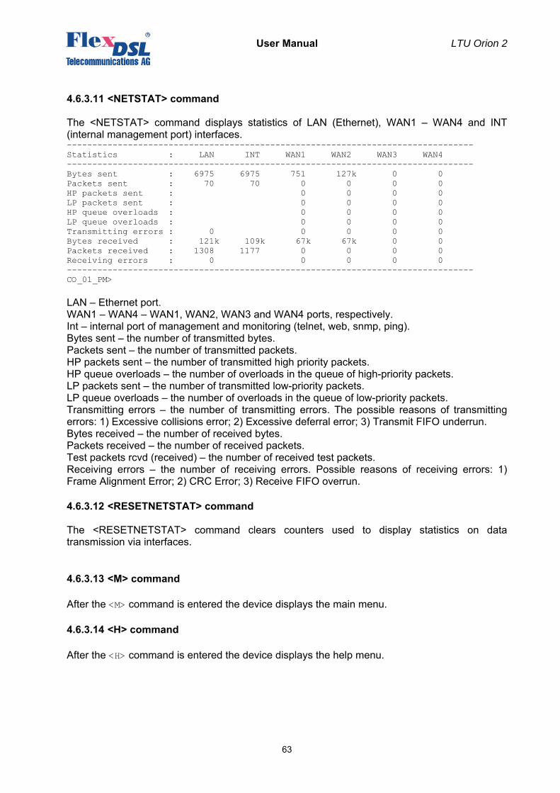
User Manual LTU Orion 2
63
4.6.3.11 <NETSTAT> command
The <NETSTAT> command displays statistics of LAN (Ethernet), WAN1 – WAN4 and INT (internal management port) interfaces. -------------------------------------------------------------------------------- Statistics : LAN INT WAN1 WAN2 WAN3 WAN4 -------------------------------------------------------------------------------- Bytes sent : 6975 6975 751 127k 0 0 Packets sent : 70 70 0 0 0 0 HP packets sent : 0 0 0 0 LP packets sent : 0 0 0 0 HP queue overloads : 0 0 0 0 LP queue overloads : 0 0 0 0 Transmitting errors : 0 0 0 0 0 Bytes received : 121k 109k 67k 67k 0 0 Packets received : 1308 1177 0 0 0 0 Receiving errors : 0 0 0 0 0 -------------------------------------------------------------------------------- CO_01_PM> LAN – Ethernet port. WAN1 – WAN4 – WAN1, WAN2, WAN3 and WAN4 ports, respectively. Int – internal port of management and monitoring (telnet, web, snmp, ping). Bytes sent – the number of transmitted bytes. Packets sent – the number of transmitted packets. HP packets sent – the number of transmitted high priority packets. HP queue overloads – the number of overloads in the queue of high-priority packets. LP packets sent – the number of transmitted low-priority packets. LP queue overloads – the number of overloads in the queue of low-priority packets. Transmitting errors – the number of transmitting errors. The possible reasons of transmitting errors: 1) Excessive collisions error; 2) Excessive deferral error; 3) Transmit FIFO underrun. Bytes received – the number of received bytes. Packets received – the number of received packets. Test packets rcvd (received) – the number of received test packets. Receiving errors – the number of receiving errors. Possible reasons of receiving errors: 1) Frame Alignment Error; 2) CRC Error; 3) Receive FIFO overrun.
4.6.3.12 <RESETNETSTAT> command
The <RESETNETSTAT> command clears counters used to display statistics on data transmission via interfaces.
4.6.3.13 <M> command
After the <M> command is entered the device displays the main menu.
4.6.3.14 <H> command
After the <H> command is entered the device displays the help menu.
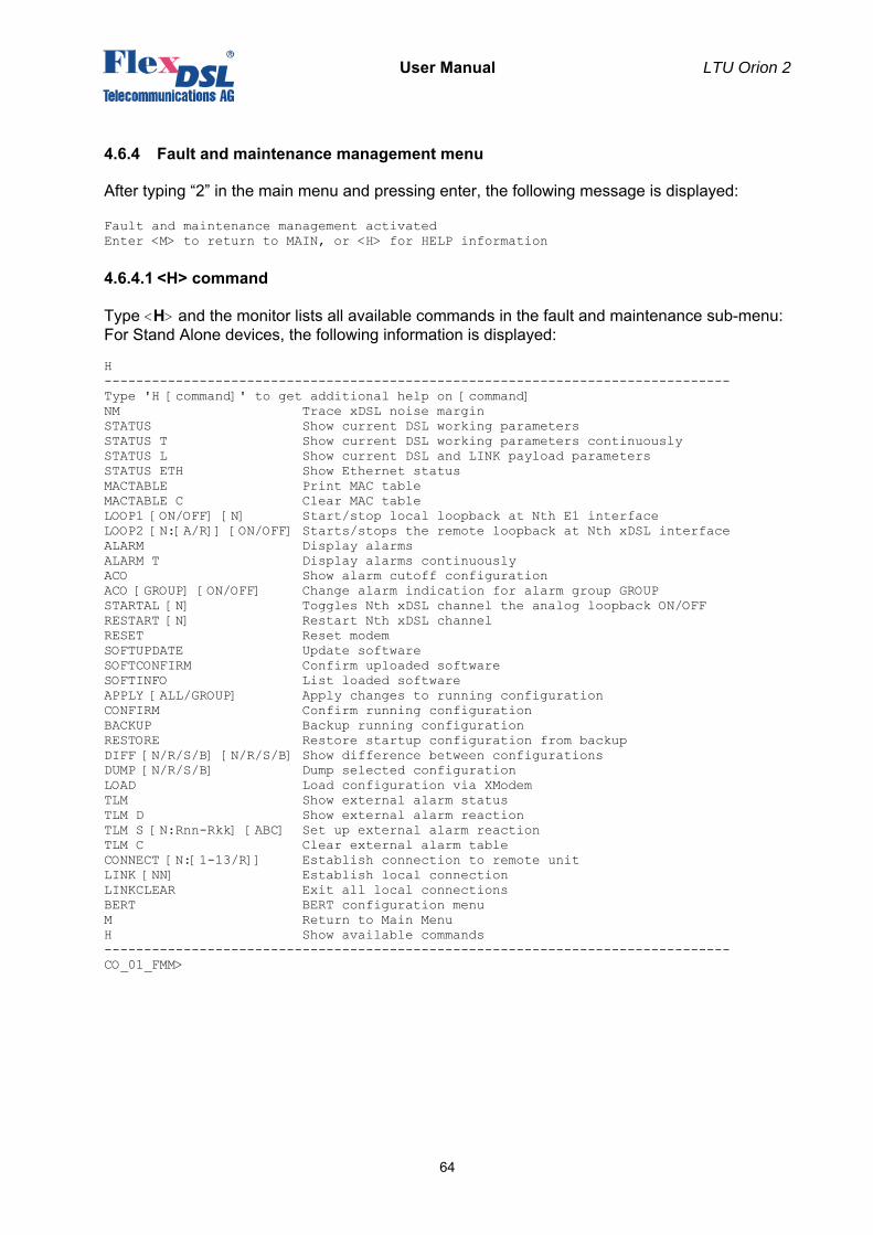
User Manual LTU Orion 2
64
4.6.4 Fault and maintenance management menu
After typing “2” in the main menu and pressing enter, the following message is displayed: Fault and maintenance management activated Enter <M> to return to MAIN, or <H> for HELP information
4.6.4.1 <H> command
Type <H> and the monitor lists all available commands in the fault and maintenance sub-menu: For Stand Alone devices, the following information is displayed: H ------------------------------------------------------------------------------- Type 'H [command]' to get additional help on [command] NM Trace xDSL noise margin STATUS Show current DSL working parameters STATUS T Show current DSL working parameters continuously STATUS L Show current DSL and LINK payload parameters STATUS ETH Show Ethernet status MACTABLE Print MAC table MACTABLE C Clear MAC table LOOP1 [ON/OFF] [N] Start/stop local loopback at Nth E1 interface LOOP2 [N:[A/R]] [ON/OFF] Starts/stops the remote loopback at Nth xDSL interface ALARM Display alarms ALARM T Display alarms continuously ACO Show alarm cutoff configuration ACO [GROUP] [ON/OFF] Change alarm indication for alarm group GROUP STARTAL [N] Toggles Nth xDSL channel the analog loopback ON/OFF RESTART [N] Restart Nth xDSL channel RESET Reset modem SOFTUPDATE Update software SOFTCONFIRM Confirm uploaded software SOFTINFO List loaded software APPLY [ALL/GROUP] Apply changes to running configuration CONFIRM Confirm running configuration BACKUP Backup running configuration RESTORE Restore startup configuration from backup DIFF [N/R/S/B] [N/R/S/B] Show difference between configurations DUMP [N/R/S/B] Dump selected configuration LOAD Load configuration via XModem TLM Show external alarm status TLM D Show external alarm reaction TLM S [N:Rnn-Rkk] [ABC] Set up external alarm reaction TLM C Clear external alarm table CONNECT [N:[1-13/R]] Establish connection to remote unit LINK [NN] Establish local connection LINKCLEAR Exit all local connections BERT BERT configuration menu M Return to Main Menu H Show available commands ------------------------------------------------------------------------------- CO_01_FMM>
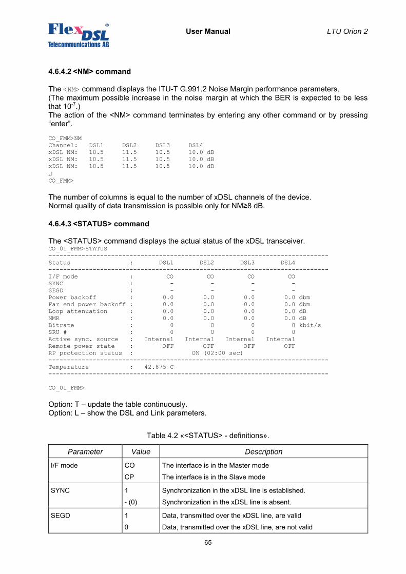
User Manual LTU Orion 2
65
4.6.4.2 <NM> command
The <NM> command displays the ITU-T G.991.2 Noise Margin performance parameters. (The maximum possible increase in the noise margin at which the BER is expected to be less that 10-7.) The action of the <NM> command terminates by entering any other command or by pressing “enter”. CO_FMM>NM Channel: DSL1 DSL2 DSL3 DSL4 xDSL NM: 10.5 11.5 10.5 10.0 dB xDSL NM: 10.5 11.5 10.5 10.0 dB xDSL NM: 10.5 11.5 10.5 10.0 dB ↵ CO_FMM> The number of columns is equal to the number of xDSL channels of the device. Normal quality of data transmission is possible only for NM≥8 dB.
4.6.4.3 <STATUS> command
The <STATUS> command displays the actual status of the xDSL transceiver. CO_01_FMM>STATUS ---------------------------------------------------------------------------- Status : DSL1 DSL2 DSL3 DSL4 ---------------------------------------------------------------------------- I/F mode : CO CO CO CO SYNC : - - - - SEGD : - - - - Power backoff : 0.0 0.0 0.0 0.0 dbm Far end power backoff : 0.0 0.0 0.0 0.0 dbm Loop attenuation : 0.0 0.0 0.0 0.0 dB NMR : 0.0 0.0 0.0 0.0 dB Bitrate : 0 0 0 0 kbit/s SRU # : 0 0 0 0 Active sync. source : Internal Internal Internal Internal Remote power state : OFF OFF OFF OFF RP protection status : ON (02:00 sec) ---------------------------------------------------------------------------- Temperature : 42.875 C ---------------------------------------------------------------------------- CO_01_FMM> Option: T – update the table continuously. Option: L – show the DSL and Link parameters.
Table 4.2 «<STATUS> - definitions».
Parameter Value Description
I/F mode CO
CP
The interface is in the Master mode
The interface is in the Slave mode
SYNC 1
- (0)
Synchronization in the xDSL line is established.
Synchronization in the xDSL line is absent.
SEGD 1
0
Data, transmitted over the xDSL line, are valid
Data, transmitted over the xDSL line, are not valid
User Manual LTU Orion 2
66
- Data are not received
Power backoff N Output signal power [dBm]
Far end power backoff N Output signal power [dBm] remote side
Loop attn N Attenuation in the loop [dB]
NMR N Maximum possible increase in the noise margin for which the BER is expected to be no less that 10-7 [dB]
Bitrate N Data transmission rate in the xDSL line [kbit/s]
SRU # N Number of regenerators in the system
Active sync. source
External
E1-1
E1-2
E1-3
E1-4
Internal
Active sync source
External sync
Е1-1 network interface
Е1-2 network interface
Е1-3 network interface
Е1-4 network interface
Internal sync source
Remote Power State ON
OFF
Remote Power Source switched on
Remote Power Source switched off
RP protection status ON (time)
OFF
Remote Power protection recovery time (switch on again) enabled
Remote Power protection recovery time disabled
Temperature N Unit temperature [С°] (only for SubRack devices) For the STATUS L explanation please see the CONFIG command explanations.
4.6.4.4 <STATUS ETH> command
The <STATUS> command displays parameters of the Ethernet port (ETH1 – ETH4), namely the rate and the operation mode: CO_01_FMM>STATUS ETH Ethernet port 1 speed/duplex: --- Ethernet port 2 speed/duplex: 100 FULL Ethernet port 3 speed/duplex: --- Ethernet port 4 speed/duplex: --- CO_01_FMM>
User Manual LTU Orion 2
67
4.6.4.5 <MACTABLE> command
The <MACTABLE> displays the dynamic table of MAC addresses: CO_FMM>MACTABLE I/F VID MAC I/F VID MAC LAN 1 00:0c:6e:ea:ee:4a LAN 1 00:c0:26:a3:6e:a2 LAN 1 00:c0:26:31:66:3e LAN 1 00:0c:f1:6e:19:8c LAN 1 00:0f:24:b5:65:d0 LAN 1 00:1f:00:00:01:eb LAN 1 02:01:00:00:00:00 LAN 1 00:c0:df:0e:b5:40 LAN 1 00:c0:26:31:5d:61 LAN 1 00:80:48:15:d3:06 LAN 1 00:c0:26:31:65:07 LAN 1 00:08:0d:b1:e9:fa CO_FMM> Option: С – clear the MACTABLE Definitions: I/F – the name of the port from which an Ethernet packet was transmitted to the internal switch. VID – VLAN ID (VLAN number) transmitted to the internal switch of the Ethernet packet. MAC – MAC address of the sender of the Ethernet packet. The size of the dynamic table of MAC addresses is 32768 cells. The MAC address table automatically deletes old records after a certain data aging time. In case there are not enough cells in the table, the aging time decreases and the stale data are deleted faster. The procedure can be repeated many times. Therefore, the table overflow does not occur even in networks incorporating thousands of devices.
4.6.4.6 <LOOP1 ON/OFF [N=1..4]> command
The <LOOP1 ON/OFF [N=1..4]> command activates/deactivates the local loopback on the network interface (E1 interface). CO_FMM>LOOP1 ON 1 Local loopback on E1-1 interface has been set CO_FMM>LOOP1 OFF 1 Local loopback on E1-1 interface has been cleared CO_FMM>
4.6.4.7 <LOOP2 [N:A/R] [ON/OFF]> command
The <LOOP2 [N:A/R] [ON/OFF]> command activates/deactivates the remote loopback on the line interface. The parameter N:A sets the number N of the DSL interface and the device address (as in the CONNECT command). In single-channel systems, the parameter N is not obligatory. The command <LOOP2> with parameters N=1..13 activates the loopback on the regenerator, whose number is specified by the value of N. The regenerators are numbered starting from the modem. The command <LOOP2> with the parameter N=R activated the remote loopback on the remote modem. CO_01_FMM>LOOP2 1:R ON Loop2 set is initiated. Loop2 is successfully set. CO_01_FMM>LOOP2 1:R OFF Loop2 reset is initiated. Loop2 is successfully cleared. CO_01_FMM>
User Manual LTU Orion 2
68
4.6.4.8 <ALARM> command
The <ALARM> command displays the actual alarm status of the local device: For systems with different numbers of E and xDSL channels, the number of columns displayed is also different, though the table structure remaind unchanged. For single-channel devices, the alarm table is displayed in the following way: CO_01_FMM>ALARM -------------------------------------------------------------------------------- Alarm status : E1-1 E1-2 E1-3 E1-4 xDSL : DSL1 DSL2 DSL3 DSL4 -------------------------------------------------------------------------------- LOS-S : on on on on LOS : on on on on LFA-S : off off off off LOSW : on on on on AIS-S : off off off off SEGD : off off off off AIS-R : off off off off BER-H : off off off off LOOP1 : off off off off ALB : off off off off BER-S : off off off off SEGA : off off off off : NM : off off off off : LA : off off off off LOOP2 : off off off off RCONF : off off off off -------------------------------------------------------------------------------- Ethernet : 1 2 3 4 Maintenance -------------------------------------------------------------------------------- LOS-E : on on on on HW-F : off DSL-F : off -------------------------------------------------------------------------------- CO_01_FMM>
Table 4.3 «<ALARM> - definitions».
Definitions (E1-1, E1-2):
LOS-S Loss of signal on the Е1 side
LFA-S Loss of frame alignment on the E1 side
AIS-S Receiving AIS on the E1 side
AIS-R Receiving AIS on the E1 side by a remote device
BER-S The block error rate on the Е1 side exceeded the admissible value
LOOP1 A loop is activated on the network interface in the direction of the Е1 equipment
Definitions (Ethernet):
LOS-E Loss of signal on the Ethernet interface
Definitions (xDSL):
LOS Loss of signal in xDSL
LOSW Loss of signal or frame alignment in xDSL (loss wire)
SEGD A failure in the line (segment degradation)
BER-H The block error rate in the line is according to G.826 ≥ 30%
ALB Analog loopback is active
SEGA Errored data or errored frame alignment (segment alarm)
NM NoiseMarging < NM threshold
User Manual LTU Orion 2
69
LA LoopAttenuation > LA threshold
LOOP2 A loop is activated on the line interface of a remote device in the direction of the local device
RCONF Configuration of the remote device is not compatible with the configuration of the local device (for example, the local device is configured to transmit Ethernet data, while the remote device is configured to transmit two E1 streams)
Definitions (Maintenance):
HW-F Hardware failure
DSL-F DSL failure Option: T – enable the continuous updating of the table of actual alarm statuses.
4.6.4.9 <AСO [GROUP ON/OFF])> command
The <AСO> command without additional parameters lists deactivated alarm relays. CO_FMM>ACO ETH1, ETH2, ETH3, ETH4 CO_01_FMM> The <ACO [GROUP ON/OFF]> command activated/deactivates the GROUP alarm relays. Available groups of alarm relays:
GROUP Description
E1-1 or E11 1st E1 channel
E1-2 or E12 2nd E1 channel
E1-3 or E13 3rd E1 channel
E1-4 or E14 4th E1 channel
E1 All E1 channels
ETH1 or ETHERNET1 1st Ethernet port
ETH2 or ETHERNET2 2nd Ethernet port
ETH3 or ETHERNET3 3rd Ethernet port
ETH4 or ETHERNET4 4th Ethernet port
ETH or ETHERNET All Ethernet ports
DSL1 or XDSL1 1st DSL channel
DSL2 or XDSL2 2nd DSL channel
DSL3 or XDSL3 3rd DSL channel
DSL4 or XDSL4 4th DSL channel
DSL or XDSL All DSL channels
RCONF RCONF alarm
CO_01_FMM>ACO E1-1 OFF ETHERNET CO_FMM>
User Manual LTU Orion 2
70
The deactivated alarm relay does not generate urgent or non-urgent alarms (i.e. does not affect the color of LEDs on the front panel and alarm relay statuses). For generators, alarm relays DSL and Ethernet can be deactivated. Note: By default in all configurations, the Ethernet alarm LED is blocked. By typing this
command, the GROUP parameter can not contain several groups of alarm statuses. For example: if it is necessary to deactivate alarm statuses of the group Е1-1 and DSL, enter the ACO command twice: first, with the parameter Е1-1, and second, with the parameter DSL. CP_FMM>ACO E1-1 ON E1-1, ETHERNET CP_FMM>ACO DSL ON E1-1, xDSL, ETHERNET CP_FMM>
4.6.4.10 <STARTAL ON/OFF N> command
The <STARTAL ON/OFF N> command starts the analog loopback at the line interface of the device with the number N (<STARTAL ON 1> starts the analog loopback at the DSL1 interface). The <STARTAL OFF N> stops this loopback. For single-channel modems, the <STARTAL> command is entered without the parameter N. CO_09_FMM>STARTAL ON 1 Analog loopback started CO_09_FMM>STARTAL OFF 1 Analog loopback stopped CO_09_FMM> Note: This command is used in the Master mode. Detach the cable from the xDSL connector
before starting the analog loopback.
4.6.4.11 <RESTART [N=1..4]> command
The <RESTART [N=1..4]> command restarts the corresponding xDSL channel. The command first causes the loss of sync between modems which later restores. For single-channel devices the command is used without any additional parameters. RR_FMM>RESTART 1 Restarting channel 1 RR_FMM>
4.6.4.12 <RESET> command
The <RESET> command restarts the device. CP_FMM>RESET
User Manual LTU Orion 2
71
4.6.4.13 <SOFTUPDATE> command
The <SOFTUPDATE> command downloads the new software into the modem by using the XMODEM or 1K XMODEM protocols. The SOFTUPDATE command downloads only the second version of the software into the flash memory. During the new software downloading the analysis of the % symbols is not performed. CP_FMM>SOFTUPDATE Flash manufacturer: Spansion Flash device: S29AL016D(02) Start address: 0x1000000 Flash size: 2048 KB Now upload program via XModem or 1K XModem CСС After the new software is successfully downloaded, a message is displayed to restart the modem. If the downloading failed, a message is displayed and the modem returns to the usual operation mode. (The operator can try again to download the software.) If the downloading was interrupted, the software is most likely damaged. The restart will result in this case in the downloading of the first version of the software.
4.6.4.14 <SOFTCONFIRM> command
The <SOFTCONFIRM> command confirms the new version of the software. After the new software is downloaded, a counter of the running software starts is switched on. If this software is not confirmed with the help of the <SOFTCONFIRM> command after the restart, it will not be valid after the next restart. CO_FMM>SOFTCONFIRM Software confirmed CO_FMM>SOFTCONFIRM Software already confirmed CO_FMM>
4.6.4.15 <SOFTINFO> command
The <SOFTINFO> command displays information about copies of the software, which are stored in the device. The device can contain two copies (different versions are possible) of the software. One of them is started after switching on, while the other is a backup software. CP_FMM>SOFTINFO 1: ver.: 1.1.3, date: 2.6.2006, length: 328k, CRC OK, fixed 2: * ver.: 1.1.4, date: 3.7.2006, length: 330k, CRC OK, confirmed CP_FMM> The asterisk shows the running downloaded version. ver – the number of the software version. date – the date of the software creation. length – the size in bytes. CRC OK/FAIL – a label showing if the software is damaged or not. The software status is displayed at the end of the corresponding line: fixed – the software status: first, basic software cannot be downloaded from the console, does not require confirmation. just loaded – the software status: downloaded second software. not confirmed – the software status: non-confirmed second software.
User Manual LTU Orion 2
72
confirmed – the software status: confirmed second software.
4.6.4.16 <APPLY /ALL/NET/LINE> command
The <APPLY /ALL/NET/VLAN/LINE/SNMP> command is used to apply changes in groups NET, VLAN or to apply changes in one of these groups. As a result, changed in the group are written from the new configuration into the running one. For example: For example: CO_FMM>APPLY Applying all configuration changes to running configuration CO_FMM>APPLY NET Applying configuration changes in group NET to running configuration
4.6.4.17 <CONFIRM> command
The <CONFIRM> command confirms the running configuration and writes it to the startup configuration. As a result, after confirmation of changes in all groups of configuration variables, they will be written from the running configuration into the startup configuration. For example: CO_FMM>CONFIRM Current running configuration is confirmed and written to startup configuration in EEPROM
4.6.4.18 <BACKUP> command
The <BACKUP> command is used to create a backup of the running configuration of the device in the EEPROM. As a result, the running configuration is written to the backup configuration. For example: CO_FMM>BACKUP Current running configuration is written to backup configuration in EEPROM CO_FMM>
4.6.4.19 <RESTORE> command
The <RESTORE> command restores the startup configuration from the backup configuration, which is written in the EEPROM. As a result, values from the backup configuration are written into the startup configuration. For example: CO_FMM>RESTORE Restored startup configuration from backup configuration. Reset modem for all changes to take effect CO_FMM> The modem should be restarted in order the restored values become valid.
User Manual LTU Orion 2
73
4.6.4.20 <DIFF N/R/S/B N/R/S/B > command
The <DIFF N/R/S/B N/R/S/B> command displays differences in configurations. The difference between four configurations is displayed: Running, New, Startup, or Backup (see Section 2.3). For example: CO_FMM>DIFF R B ------------------------------------------------------------------------ Running configuration Backup configuration ------------------------------------------------------------------------ VLAN.VLANMASK.3 00 01 | 00 07 ------------------------------------------------------------------------ CO_FMM> The command displays the name of the difference parameter and data from two configurations. In the above example one can see that the VLANMASK parameter of interface 3 (WAN2) of the VLAN group in the running configuration differs from the backup configuration. If there are no differences, the result is presented as follows: CO_FMM>DIFF N R ------------------------------------------------------------------------ New configuration Running configuration ------------------------------------------------------------------------ --- No differences --- --- No differences --- ------------------------------------------------------------------------ CO_FMM>
4.6.4.21 <DUMP N/R/S/B > command
The <DUMP N/R/S/B> command displays the dump of the corresponding configuration: Running, New, Startup or Backup. The text format used by the command can be also employed for reading or for the configuration downloading in the modem with the help of the LOAD command (see below). For example: CO_FMM>DUMP R ------------------------------------------------------------------------ Dump of running configuration ------------------------------------------------------------------------ NET.MAC_ADDRESS 00 0F D9 00 10 03 M.DEVICE_ID 00 00 00 00 00 00 00 00 00 43 4F 4D 4D 4F 4E 00\ 00 00 00 00 00 00 00 00 00 00 00 00 00 00 00 00\ 00 NET.MAC_SPEED 5A SNMP.TRAPIP.0 00 00 00 00 SNMP.TRAPIP.1 00 00 00 00 SNMP.COMMUNITY 43 4F 4D 4D 4F 4E 00 20 60 00 00 13 00 02 B2 3C\ 00 18 65 44 00 05 5E 2C FF FF FF FF 00 17 59 F8\ 00 M.ALARM_CUTOFF 02 NET.IP C0 A8 5A 14 NET.NETMASK FF FF FF 00

User Manual LTU Orion 2
74
NET.GATEWAY C0 A8 5A 64 NET.PPPREMIP C0 A8 5A 5A PE1.G704.0 01 SE1.G704.1 01 PE1.CRC4DET.0 00 SE1.CRC4DET.1 00 ... ------------------------------------------------------------------------ CO_FMM> The results of the command show the coded configuration of the device and can be copied from the terminal window into the notepad as well as saved on any data carrier. This txt file can be downloaded into a similar device with the help of the LOAD command via the XModem or 1K XModem protocols.
4.6.4.22 <LOAD> command
The <LOAD> command downloads the configuration file obtained with the help of the DUMP command into a device via the XModem or 1K XModem protocols. For Windows 95 or above, this procedure can be performed with the help of the HyperTerminal program. By typing LOAD, the following text will be displayed in the terminal window: CO_FMM>LOAD Now upload configuration via XModem or 1K XModem C Select "Send File” in the Transfer menu. Select the protocol XModem or 1K XModem in the window which appears. Select the downloading configuration file and click the Send button. If downloading is successful, a message will appear to reset the modem: Configuration was loaded successfully. For all configuration options to apply, type RESET to reset modem. CO_FMM> If the configuration file contained errors, a message with the number of the line in which the error was detected will be displayed. The configuration of the device in this case will not change.
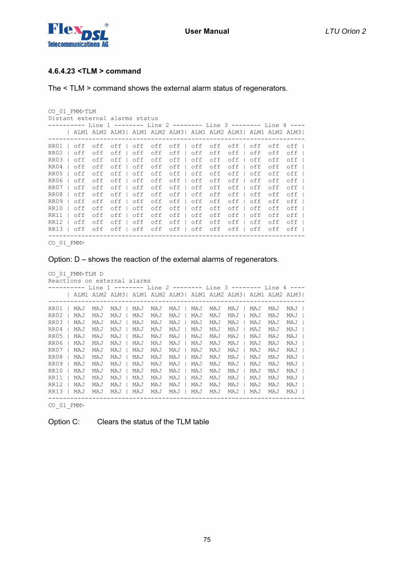
User Manual LTU Orion 2
75
4.6.4.23 <TLM > command
The < TLM > command shows the external alarm status of regenerators. CO_01_FMM>TLM Distant external alarms status ---------- Line 1 -------- Line 2 -------- Line 3 -------- Line 4 ---- | ALM1 ALM2 ALM3| ALM1 ALM2 ALM3| ALM1 ALM2 ALM3| ALM1 ALM2 ALM3| ---------------------------------------------------------------------- RR01 | off off off | off off off | off off off | off off off | RR02 | off off off | off off off | off off off | off off off | RR03 | off off off | off off off | off off off | off off off | RR04 | off off off | off off off | off off off | off off off | RR05 | off off off | off off off | off off off | off off off | RR06 | off off off | off off off | off off off | off off off | RR07 | off off off | off off off | off off off | off off off | RR08 | off off off | off off off | off off off | off off off | RR09 | off off off | off off off | off off off | off off off | RR10 | off off off | off off off | off off off | off off off | RR11 | off off off | off off off | off off off | off off off | RR12 | off off off | off off off | off off off | off off off | RR13 | off off off | off off off | off off off | off off off | ---------------------------------------------------------------------- CO_01_FMM> Option: D – shows the reaction of the external alarms of regenerators. CO_01_FMM>TLM D Reactions on external alarms ---------- Line 1 -------- Line 2 -------- Line 3 -------- Line 4 ---- | ALM1 ALM2 ALM3| ALM1 ALM2 ALM3| ALM1 ALM2 ALM3| ALM1 ALM2 ALM3| ---------------------------------------------------------------------- RR01 | MAJ MAJ MAJ | MAJ MAJ MAJ | MAJ MAJ MAJ | MAJ MAJ MAJ | RR02 | MAJ MAJ MAJ | MAJ MAJ MAJ | MAJ MAJ MAJ | MAJ MAJ MAJ | RR03 | MAJ MAJ MAJ | MAJ MAJ MAJ | MAJ MAJ MAJ | MAJ MAJ MAJ | RR04 | MAJ MAJ MAJ | MAJ MAJ MAJ | MAJ MAJ MAJ | MAJ MAJ MAJ | RR05 | MAJ MAJ MAJ | MAJ MAJ MAJ | MAJ MAJ MAJ | MAJ MAJ MAJ | RR06 | MAJ MAJ MAJ | MAJ MAJ MAJ | MAJ MAJ MAJ | MAJ MAJ MAJ | RR07 | MAJ MAJ MAJ | MAJ MAJ MAJ | MAJ MAJ MAJ | MAJ MAJ MAJ | RR08 | MAJ MAJ MAJ | MAJ MAJ MAJ | MAJ MAJ MAJ | MAJ MAJ MAJ | RR09 | MAJ MAJ MAJ | MAJ MAJ MAJ | MAJ MAJ MAJ | MAJ MAJ MAJ | RR10 | MAJ MAJ MAJ | MAJ MAJ MAJ | MAJ MAJ MAJ | MAJ MAJ MAJ | RR11 | MAJ MAJ MAJ | MAJ MAJ MAJ | MAJ MAJ MAJ | MAJ MAJ MAJ | RR12 | MAJ MAJ MAJ | MAJ MAJ MAJ | MAJ MAJ MAJ | MAJ MAJ MAJ | RR13 | MAJ MAJ MAJ | MAJ MAJ MAJ | MAJ MAJ MAJ | MAJ MAJ MAJ | ---------------------------------------------------------------------- CO_01_FMM> Option C: Clears the status of the TLM table
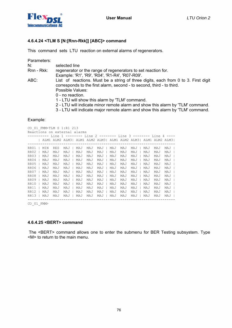
User Manual LTU Orion 2
76
4.6.4.24 <TLM S [N:[Rnn-Rkk]] [ABC]> command
This command sets LTU reaction on external alarms of regenerators. Parameters: N: selected line Rnn - Rkk: regenerator or the range of regenerators to set reaction for.
Example: 'R1', 'R9', 'R04', 'R1-R4', 'R07-R09'. ABC: List of reactions. Must be a string of three digits, each from 0 to 3. First digit
corresponds to the first alarm, second - to second, third - to third. Possible Values: 0 - no reaction.
1 - LTU will show this alarm by 'TLM' command. 2 - LTU will indicate minor remote alarm and show this alarm by 'TLM' command. 3 - LTU will indicate major remote alarm and show this alarm by 'TLM' command. Example: CO_01_FMM>TLM S 1:R1 213 Reactions on external alarms ---------- Line 1 -------- Line 2 -------- Line 3 -------- Line 4 ---- | ALM1 ALM2 ALM3| ALM1 ALM2 ALM3| ALM1 ALM2 ALM3| ALM1 ALM2 ALM3| ---------------------------------------------------------------------- RR01 | MIN RES MAJ | MAJ MAJ MAJ | MAJ MAJ MAJ | MAJ MAJ MAJ | RR02 | MAJ MAJ MAJ | MAJ MAJ MAJ | MAJ MAJ MAJ | MAJ MAJ MAJ | RR03 | MAJ MAJ MAJ | MAJ MAJ MAJ | MAJ MAJ MAJ | MAJ MAJ MAJ | RR04 | MAJ MAJ MAJ | MAJ MAJ MAJ | MAJ MAJ MAJ | MAJ MAJ MAJ | RR05 | MAJ MAJ MAJ | MAJ MAJ MAJ | MAJ MAJ MAJ | MAJ MAJ MAJ | RR06 | MAJ MAJ MAJ | MAJ MAJ MAJ | MAJ MAJ MAJ | MAJ MAJ MAJ | RR07 | MAJ MAJ MAJ | MAJ MAJ MAJ | MAJ MAJ MAJ | MAJ MAJ MAJ | RR08 | MAJ MAJ MAJ | MAJ MAJ MAJ | MAJ MAJ MAJ | MAJ MAJ MAJ | RR09 | MAJ MAJ MAJ | MAJ MAJ MAJ | MAJ MAJ MAJ | MAJ MAJ MAJ | RR10 | MAJ MAJ MAJ | MAJ MAJ MAJ | MAJ MAJ MAJ | MAJ MAJ MAJ | RR11 | MAJ MAJ MAJ | MAJ MAJ MAJ | MAJ MAJ MAJ | MAJ MAJ MAJ | RR12 | MAJ MAJ MAJ | MAJ MAJ MAJ | MAJ MAJ MAJ | MAJ MAJ MAJ | RR13 | MAJ MAJ MAJ | MAJ MAJ MAJ | MAJ MAJ MAJ | MAJ MAJ MAJ | ---------------------------------------------------------------------- CO_01_FMM>
4.6.4.25 <BERT> command
The <BERT> command allows one to enter the submenu for BER Testing subsystem. Type <M> to return to the main menu.
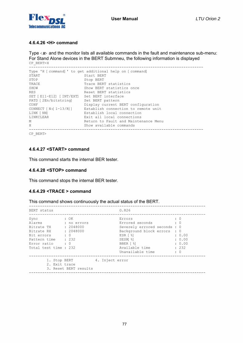
User Manual LTU Orion 2
77
4.6.4.26 <H> command
Type <H> and the monitor lists all available commands in the fault and maintenance sub-menu: For Stand Alone devices in the BERT Submneu, the following information is displayed CP_BERT>H ------------------------------------------------------------------------------- Type 'H [command]' to get additional help on [command] START Start BERT STOP Stop BERT TRACE Trace BERT statistics SHOW Show BERT statistics once RES Reset BERT statistics SET [E11-E12] [INT/EXT] Set BERT interface PATD [2En/bitstring] Set BERT pattern CONF Display current BERT configuration CONNECT [N:[1-13/R]] Establish connection to remote unit LINK [NN] Establish local connection LINKCLEAR Exit all local connections M Return to Fault and Maintenance Menu H Show available commands ------------------------------------------------------------------------------- CP_BERT>
4.6.4.27 <START> command
This command starts the internal BER tester.
4.6.4.28 <STOP> command
This command stops the internal BER tester.
4.6.4.29 <TRACE > command
This command shows continuously the actual status of the BERT. -------------------------------------------------------------------------------- BERT status G.826 -------------------------------------------------------------------------------- Sync : OK Errors : 0 Alarms : no errors Errored seconds : 0 Bitrate TX : 2048000 Severely errored seconds : 0 Bitrate RX : 2048000 Background block errors : 0 Bit errors : 0 ESR [%] : 0.00 Pattern time : 232 SESR[%] : 0.00 Error ratio : 0 BBER [%] : 0.00 Total test time : 232 Available time : 232 Unavailable time : 0 -------------------------------------------------------------------------------- 1. Stop BERT 4. Inject error 2. Exit trace 3. Reset BERT results --------------------------------------------------------------------------------
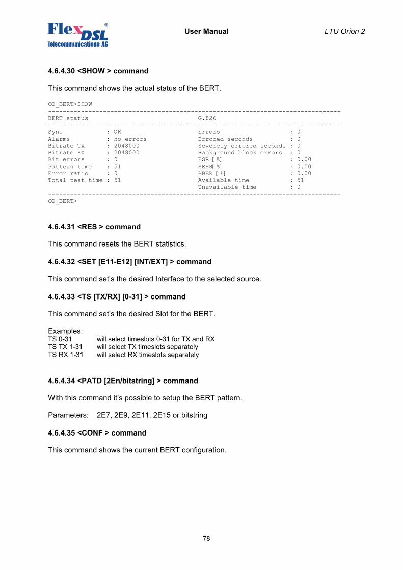
User Manual LTU Orion 2
78
4.6.4.30 <SHOW > command
This command shows the actual status of the BERT. CO_BERT>SHOW -------------------------------------------------------------------------------- BERT status G.826 -------------------------------------------------------------------------------- Sync : OK Errors : 0 Alarms : no errors Errored seconds : 0 Bitrate TX : 2048000 Severely errored seconds : 0 Bitrate RX : 2048000 Background block errors : 0 Bit errors : 0 ESR [%] : 0.00 Pattern time : 51 SESR[%] : 0.00 Error ratio : 0 BBER [%] : 0.00 Total test time : 51 Available time : 51 Unavailable time : 0 -------------------------------------------------------------------------------- CO_BERT>
4.6.4.31 <RES > command
This command resets the BERT statistics.
4.6.4.32 <SET [E11-E12] [INT/EXT] > command
This command set’s the desired Interface to the selected source.
4.6.4.33 <TS [TX/RX] [0-31] > command
This command set’s the desired Slot for the BERT. Examples: TS 0-31 will select timeslots 0-31 for TX and RX TS TX 1-31 will select TX timeslots separately TS RX 1-31 will select RX timeslots separately
4.6.4.34 <PATD [2En/bitstring] > command
With this command it’s possible to setup the BERT pattern. Parameters: 2E7, 2E9, 2E11, 2E15 or bitstring
4.6.4.35 <CONF > command
This command shows the current BERT configuration.
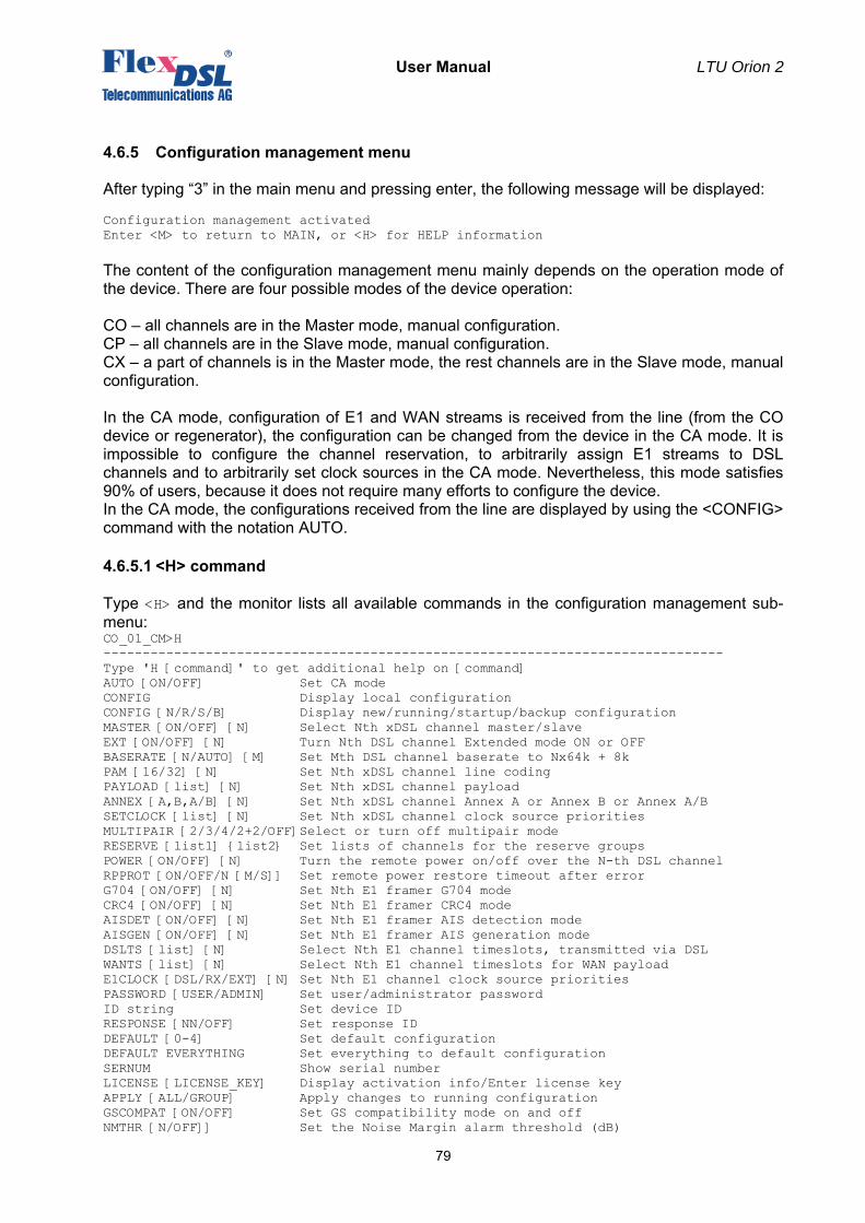
User Manual LTU Orion 2
79
4.6.5 Configuration management menu
After typing “3” in the main menu and pressing enter, the following message will be displayed: Configuration management activated Enter <M> to return to MAIN, or <H> for HELP information The content of the configuration management menu mainly depends on the operation mode of the device. There are four possible modes of the device operation: CO – all channels are in the Master mode, manual configuration. CP – all channels are in the Slave mode, manual configuration. CX – a part of channels is in the Master mode, the rest channels are in the Slave mode, manual configuration. In the CA mode, configuration of E1 and WAN streams is received from the line (from the CO device or regenerator), the configuration can be changed from the device in the CA mode. It is impossible to configure the channel reservation, to arbitrarily assign E1 streams to DSL channels and to arbitrarily set clock sources in the CA mode. Nevertheless, this mode satisfies 90% of users, because it does not require many efforts to configure the device. In the CA mode, the configurations received from the line are displayed by using the <CONFIG> command with the notation AUTO.
4.6.5.1 <H> command
Type <H> and the monitor lists all available commands in the configuration management sub-menu: CO_01_CM>H ------------------------------------------------------------------------------- Type 'H [command]' to get additional help on [command] AUTO [ON/OFF] Set CA mode CONFIG Display local configuration CONFIG [N/R/S/B] Display new/running/startup/backup configuration MASTER [ON/OFF] [N] Select Nth xDSL channel master/slave EXT [ON/OFF] [N] Turn Nth DSL channel Extended mode ON or OFF BASERATE [N/AUTO] [M] Set Mth DSL channel baserate to Nx64k + 8k PAM [16/32] [N] Set Nth xDSL channel line coding PAYLOAD [list] [N] Set Nth xDSL channel payload ANNEX [A,B,A/B] [N] Set Nth xDSL channel Annex A or Annex B or Annex A/B SETCLOCK [list] [N] Set Nth xDSL channel clock source priorities MULTIPAIR [2/3/4/2+2/OFF]Select or turn off multipair mode RESERVE [list1] {list2} Set lists of channels for the reserve groups POWER [ON/OFF] [N] Turn the remote power on/off over the N-th DSL channel RPPROT [ON/OFF/N [M/S]] Set remote power restore timeout after error G704 [ON/OFF] [N] Set Nth E1 framer G704 mode CRC4 [ON/OFF] [N] Set Nth E1 framer CRC4 mode AISDET [ON/OFF] [N] Set Nth E1 framer AIS detection mode AISGEN [ON/OFF] [N] Set Nth E1 framer AIS generation mode DSLTS [list] [N] Select Nth E1 channel timeslots, transmitted via DSL WANTS [list] [N] Select Nth E1 channel timeslots for WAN payload E1CLOCK [DSL/RX/EXT] [N] Set Nth E1 channel clock source priorities PASSWORD [USER/ADMIN] Set user/administrator password ID string Set device ID RESPONSE [NN/OFF] Set response ID DEFAULT [0-4] Set default configuration DEFAULT EVERYTHING Set everything to default configuration SERNUM Show serial number LICENSE [LICENSE_KEY] Display activation info/Enter license key APPLY [ALL/GROUP] Apply changes to running configuration GSCOMPAT [ON/OFF] Set GS compatibility mode on and off NMTHR [N/OFF]] Set the Noise Margin alarm threshold (dB)
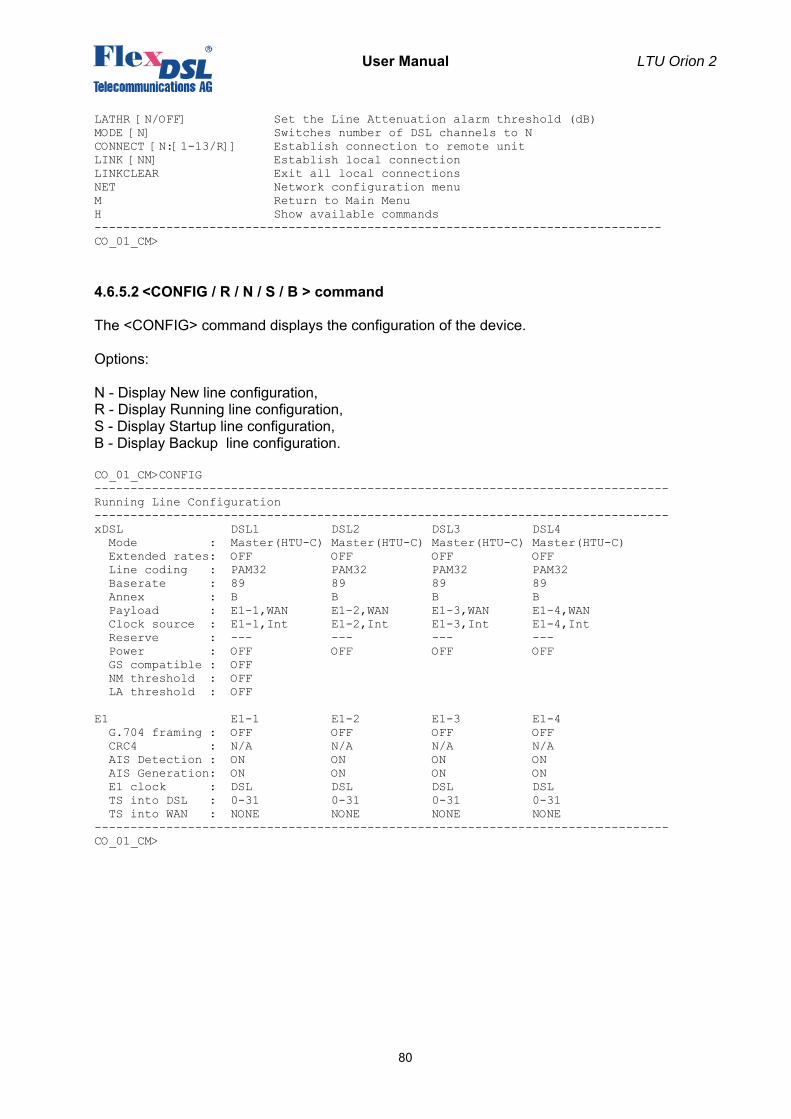
User Manual LTU Orion 2
80
LATHR [N/OFF] Set the Line Attenuation alarm threshold (dB) MODE [N] Switches number of DSL channels to N CONNECT [N:[1-13/R]] Establish connection to remote unit LINK [NN] Establish local connection LINKCLEAR Exit all local connections NET Network configuration menu M Return to Main Menu H Show available commands ------------------------------------------------------------------------------- CO_01_CM>
4.6.5.2 <CONFIG / R / N / S / B > command
The <CONFIG> command displays the configuration of the device. Options: N - Display New line configuration, R - Display Running line configuration, S - Display Startup line configuration, B - Display Backup line configuration. CO_01_CM>CONFIG -------------------------------------------------------------------------------- Running Line Configuration -------------------------------------------------------------------------------- xDSL DSL1 DSL2 DSL3 DSL4 Mode : Master(HTU-C) Master(HTU-C) Master(HTU-C) Master(HTU-C) Extended rates: OFF OFF OFF OFF Line coding : PAM32 PAM32 PAM32 PAM32 Baserate : 89 89 89 89 Annex : B B B B Payload : E1-1,WAN E1-2,WAN E1-3,WAN E1-4,WAN Clock source : E1-1,Int E1-2,Int E1-3,Int E1-4,Int Reserve : --- --- --- --- Power : OFF OFF OFF OFF GS compatible : OFF NM threshold : OFF LA threshold : OFF E1 E1-1 E1-2 E1-3 E1-4 G.704 framing : OFF OFF OFF OFF CRC4 : N/A N/A N/A N/A AIS Detection : ON ON ON ON AIS Generation: ON ON ON ON E1 clock : DSL DSL DSL DSL TS into DSL : 0-31 0-31 0-31 0-31 TS into WAN : NONE NONE NONE NONE -------------------------------------------------------------------------------- CO_01_CM>
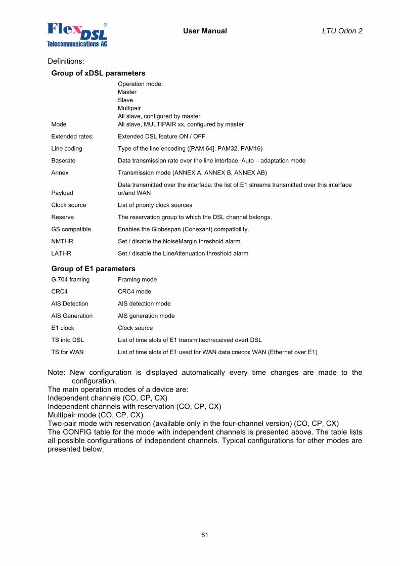
User Manual LTU Orion 2
81
Definitions: Group of xDSL parameters
Mode
Operation mode: Master Slave Multipair All slave, configured by master All slave, MULTIPAIR xx, configured by master
Extended rates: Extended DSL feature ON / OFF
Line coding Type of the line encoding ([PAM 64], PAM32, PAM16)
Baserate Data transmission rate over the line interface. Auto – adaptation mode
Annex Transmission mode (ANNEX A, ANNEX B, ANNEX AB)
Payload Data transmitted over the interface: the list of E1 streams transmitted over this interface or/and WAN
Clock source List of priority clock sources
Reserve The reservation group to which the DSL channel belongs.
GS compatible Enables the Globespan (Conexant) compatibility.
NMTHR Set / disable the NoiseMargin threshold alarm.
LATHR Set / disable the LineAttenuation threshold alarm
Group of E1 parameters G.704 framing Framing mode
CRC4 CRC4 mode
AIS Detection AIS detection mode
AIS Generation AIS generation mode
E1 clock Clock source
TS into DSL List of time slots of E1 transmitted/received overt DSL
TS for WAN List of time slots of E1 used for WAN data список WAN (Ethernet over E1)
Note: New configuration is displayed automatically every time changes are made to the
configuration. The main operation modes of a device are: Independent channels (CO, СP, CX) Independent channels with reservation (CO, СP, CX) Multipair mode (CO, СP, CX) Two-pair mode with reservation (available only in the four-channel version) (CO, СP, CX) The CONFIG table for the mode with independent channels is presented above. The table lists all possible configurations of independent channels. Typical configurations for other modes are presented below.
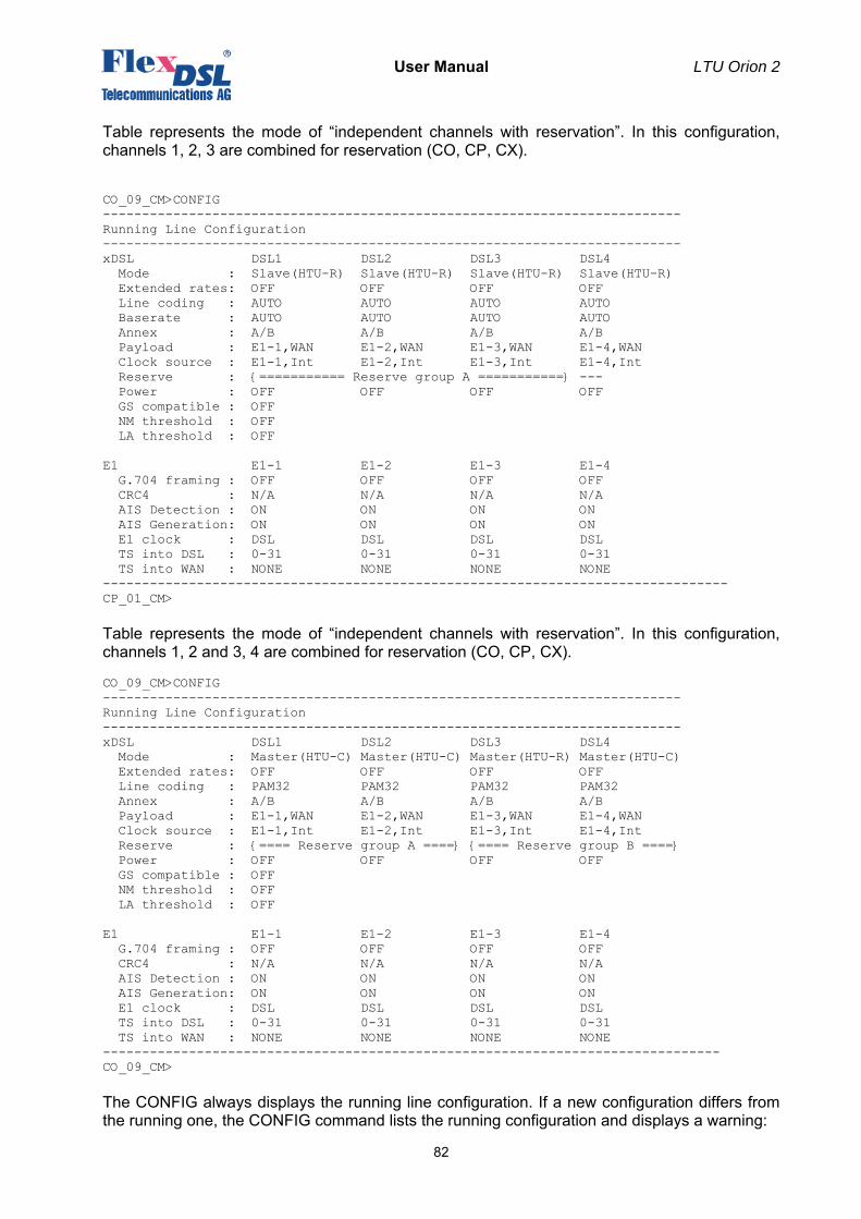
User Manual LTU Orion 2
82
Table represents the mode of “independent channels with reservation”. In this configuration, channels 1, 2, 3 are combined for reservation (CO, CP, CX). CO_09_CM>CONFIG -------------------------------------------------------------------------- Running Line Configuration -------------------------------------------------------------------------- xDSL DSL1 DSL2 DSL3 DSL4 Mode : Slave(HTU-R) Slave(HTU-R) Slave(HTU-R) Slave(HTU-R) Extended rates: OFF OFF OFF OFF Line coding : AUTO AUTO AUTO AUTO Baserate : AUTO AUTO AUTO AUTO Annex : A/B A/B A/B A/B Payload : E1-1,WAN E1-2,WAN E1-3,WAN E1-4,WAN Clock source : E1-1,Int E1-2,Int E1-3,Int E1-4,Int Reserve : {=========== Reserve group A ===========} --- Power : OFF OFF OFF OFF GS compatible : OFF NM threshold : OFF LA threshold : OFF E1 E1-1 E1-2 E1-3 E1-4 G.704 framing : OFF OFF OFF OFF CRC4 : N/A N/A N/A N/A AIS Detection : ON ON ON ON AIS Generation: ON ON ON ON E1 clock : DSL DSL DSL DSL TS into DSL : 0-31 0-31 0-31 0-31 TS into WAN : NONE NONE NONE NONE -------------------------------------------------------------------------------- CP_01_CM> Table represents the mode of “independent channels with reservation”. In this configuration, channels 1, 2 and 3, 4 are combined for reservation (CO, CP, CX). CO_09_CM>CONFIG -------------------------------------------------------------------------- Running Line Configuration -------------------------------------------------------------------------- xDSL DSL1 DSL2 DSL3 DSL4 Mode : Master(HTU-C) Master(HTU-C) Master(HTU-R) Master(HTU-C) Extended rates: OFF OFF OFF OFF Line coding : PAM32 PAM32 PAM32 PAM32 Annex : A/B A/B A/B A/B Payload : E1-1,WAN E1-2,WAN E1-3,WAN E1-4,WAN Clock source : E1-1,Int E1-2,Int E1-3,Int E1-4,Int Reserve : {==== Reserve group A ====} {==== Reserve group B ====} Power : OFF OFF OFF OFF GS compatible : OFF NM threshold : OFF LA threshold : OFF E1 E1-1 E1-2 E1-3 E1-4 G.704 framing : OFF OFF OFF OFF CRC4 : N/A N/A N/A N/A AIS Detection : ON ON ON ON AIS Generation: ON ON ON ON E1 clock : DSL DSL DSL DSL TS into DSL : 0-31 0-31 0-31 0-31 TS into WAN : NONE NONE NONE NONE -------------------------------------------------------------------------------CO_09_CM> The CONFIG always displays the running line configuration. If a new configuration differs from the running one, the CONFIG command lists the running configuration and displays a warning:
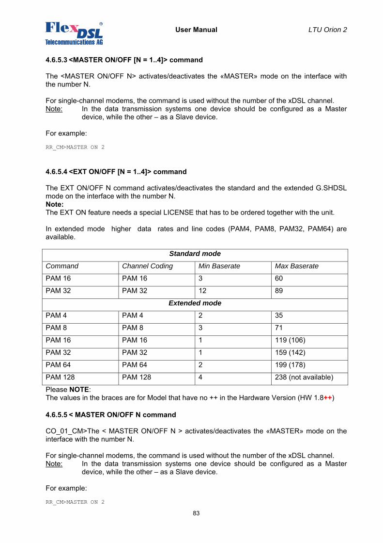
User Manual LTU Orion 2
83
4.6.5.3 <MASTER ON/OFF [N = 1..4]> command
The <MASTER ON/OFF N> activates/deactivates the «MASTER» mode on the interface with the number N. For single-channel modems, the command is used without the number of the xDSL channel. Note: In the data transmission systems one device should be configured as a Master
device, while the other – as a Slave device. For example: RR_CM>MASTER ON 2
4.6.5.4 <EXT ON/OFF [N = 1..4]> command
The EXT ON/OFF N command activates/deactivates the standard and the extended G.SHDSL mode on the interface with the number N. Note: The EXT ON feature needs a special LICENSE that has to be ordered together with the unit. In extended mode higher data rates and line codes (PAM4, PAM8, PAM32, PAM64) are available.
Standard mode
Command Channel Coding Min Baserate Max Baserate
PAM 16 PAM 16 3 60
PAM 32 PAM 32 12 89
Extended mode
PAM 4 PAM 4 2 35
PAM 8 PAM 8 3 71
PAM 16 PAM 16 1 119 (106)
PAM 32 PAM 32 1 159 (142)
PAM 64 PAM 64 2 199 (178)
PAM 128 PAM 128 4 238 (not available)
Please NOTE: The values in the braces are for Model that have no ++ in the Hardware Version (HW 1.8++)
4.6.5.5 < MASTER ON/OFF N command
CO_01_CM>The < MASTER ON/OFF N > activates/deactivates the «MASTER» mode on the interface with the number N. For single-channel modems, the command is used without the number of the xDSL channel. Note: In the data transmission systems one device should be configured as a Master
device, while the other – as a Slave device. For example: RR_CM>MASTER ON 2
User Manual LTU Orion 2
84
4.6.5.6 <BASERATE K/AUTO [N=1..4]> command
The <BASERATE K [N=1..4]> command sets the transmission rate K over the line xDSL interface, where N is the number of the interface. For PAM16 the available rates (BASERATE) lie in the range from 3 to 60, and for PAM32 – from 12 to 89.
Table 4.4 “Available rates (BASERATE) for different types of coding”.
Coding type: Parameter: Values: Description:
PAM16 N 3..60 Transmission rate over the line interface (N*64+8) kbit/s.
PAM32 12..89
Warning! Use codes with the lowest number of levels (PAM16) for low rates.
On the Slave device, the <BASERATE AUTO> command adapts the rate of the Slave device to the rate of the Master device. In this case, PAM and Annex are automatically detected (opposite Annex in the <CONFIG> configuration AB appears, opposite PAM – Auto). The command does not change the Annex and PAM modes in the configuration. In the Slave mode, the <BASERATE AUTO> command automatically detects all configurations. For modems with one xDSL channel, the command is entered without typing the number of the xDSL channel.
4.6.5.7 <PAM 16/32/64 [N]> command
The <PAM 16/32> command sets the number of levels in the line code. The following options are possible – 16, 32 & 64 for EXT mode ON For modems with one xDSL channel, the following command is used: CO_01_CM>PAM 16 Compatibility with the Orion modem is achieved by setting BASERATE in the range from 3 to 32 and by setting the line coding equal to PAM 16. The <BASERATE AUTO> command activates the automatic detection of PAM and Annex.
4.6.5.8 <PAYLOAD list/NONE [N=1..4]> command
The <PAYLOAD list/NONE [N=1..4]> command sets the list of streams transmitted over the xDSL channel. Here, N is the number of the xDSL channel. The parameter list displays the list of E1 interfaces and WAN interfaces (Ethernet), separated by comma. The E1 interface may be denoted both by a short-form (for example, E1-1, E11), and by numbers (for example, 1). Spaces in the list are not allowed. The parameter NONE deactivates transmission of E1 and WAN over this xDSL interface. If two streams E1 and WAN are selected to be transmitted over xDSL, the number of time slots of the xDSL channel used to transmit Ethernet data is calculated as BASERATE minus the number of time slots of the E1 stream transmitted over xDSL. For example, if BASERATE is 89, and time slots 0-31 (<DSLTS 0-31>) of the Е1 interface are transmitted over xDSL, 57 time slots of the xDSL stream (57*64 = 3648 kbit/sec) will be used to transmit WAN (Ethernet) by the <PAYLOAD E1-1, WAN> command. For modems with one xDSL channel, the command is as follows:
User Manual LTU Orion 2
85
CO_CM>PAYLOAD WAN CO_CM>PAYLOAD E11,WAN CO_CM>PAYLOAD NONE
4.6.5.9 <ANNEX A/B/AB [N=1..4]> command
The <ANNEX A/B [N=1..4]> command enables the transmission standard: G.991.2 ANNEX A or G.991.2 ANNEX B, where N is the number of the interface. The <ANNEX AB> automatically selects the transmission standard. Note: If devices use different transmission standards, synchronization will not be
established between them.
4.6.5.10 <SETCLOCK list [N=1..4]> command
The <SETCLOCK list [N=1..4]> command sets the priority list of clock sources for the xDSL channel, where N is the number of the xDSL channel. The possible clock sources are: • External sync source. Marked as EXT, EXTERNAL (only for Sub-Rack modems);
• first E1 channel. Marked as 1, E11, E1-1, E1_1;
• second E2 channel. Marked as 1, E12, E1-2, E1_2;
• internal sync source. Marked as INT, INTERNAL.
The external clock source should be either the first one in the priority list or be not used at all. The next clock sources in the list should be E1 channels. The internal clock source should be the last one in the priority list. It is not necessary to type it in the command. The parameter N can be absent for single-channel modems. The list of priority clock sources should contain only those E1 channels, which are used to transmit data over the xDSL channel. If the xDSL channel is not used to transmit E1 streams, it is possible to set any of the E1 channel as a reference clock source or to use the external (EXTERNAL) clock. Note: If the list of E1 channels transmitted over DSL is changed by the PAYLOAD command,
this command can change the list so that it corresponds to the previous two criteria. For example: CO_09_CM>SETCLOCK EXT,E1-1,E1-2 CO_CM>SETCLOCK INT
4.6.5.11 <MULTIPAIR [MODE]> command
The <MULTIPAIR> command activates multipair mode, which allows one to merge DSL channels. Groups of 2, 3 and 4 channels can be merged in the multipair mode. The following variants are possible: CO_01_CM>MULTIPAIR 2 CO_01_CM>MULTIPAIR 3 CO_01_CM>MULTIPAIR 4 The two-pair mode can be activated simultaneously for two pairs of channels: 1-2 and 3-4. The 2+2 mode is also possible: CO_01_CM>MULTIPAIR 2+2
User Manual LTU Orion 2
86
4.6.5.12 <RESERVE [list]>, <RESERVE [list] [list]> command
The <RESERVE> command allows combining xDSL channels into groups in order to reserve them. There can be no more than 2 groups in the system with 4 DSL channels. The reservation groups are called A and B groups. The parameter sets the list of channel numbers separated by a comma. To simplify configuration and maintenance of devices, anly groups of successive channels can be reserved. To configure the reserve group, type the following command: CO_01_CM>RESERVE 1,2 To configure both reserve groups type the command as follows. Note then groups should not cross one another: CO_01_CM>RESERVE 1,2 3,4 The parameter NONE deactivates reservation: CO_01_CM>RESERVE NONE
4.6.5.13 <POWER ON/OFF [N=1..4]> command
The <POWER ON/OFF [N]> command activates/deactivates the remote power source for the selected [N] DSL channel. Please refer to the chapter Remote power & wetting- current supply and consumption modes.
4.6.5.14 <RPPROT T/OFF [SEC/MIN]> command
The <RPPROT T/OFF [SEC/MIN]> activates / deactivates the remote power source protection feature. Parameters: T time value for chosen time unit SEC / MIN selected time unit
4.6.5.15 <G704 ON/OFF [N]> command
The <G704 ON/OFF [N]> command activates/deactivates the ITU-T G.704 framed mode for the Е1 interface, where N is the number of the E interface. The <G704 ON> activates the ITU-T G.704 framed mode. The <G704 OFF> deactivates the ITU-T G.704 framed mode, i.e., the devices starts operating in the so-called transparent mode. For modems with one Е1 channel the command is the following: CO_CM>G704 ON
User Manual LTU Orion 2
87
4.6.5.16 <CRC4 ON/OFF [N]> command
The <CRC4 ON/OFF [N]> command activates/deactivates the CRC4 mode for the E1 channels, where N is the number of the E1 channel. For modems with one Е1 channel the command is the following: CO_CM>CRC4 ON Note: The command is available in the G.704 framed mode.
4.6.5.17 <AISGEN ON/OFF [N]>, <AISDET ON/OFF [N]> commands
The <AISGEN ON [N]> command activates the AIS Generation mode for the E1 interface, where N is the number of the E1 interface. The <AISGEN OFF> command deactivates the AIS Generation mode. The <AISDET ON [N]> command activates the AIS Detection mode for the E1 interface, where N is the number of the E1 interface. The <AISDET OFF> command deactivates the AIS Detection mode. For modems with one Е1 channel the command is the following: CO_CM>AISGEN ON CO_CM>AISDET ON
4.6.5.18 <DSLTS list/NONE [N=1..4]> command
The <DSLTS list/NONE [N=1..4]> command sets transmitted/received time slots of the given E1 channel to be transmitted over the xDSL channel. Here, N is the number of the E1 interface. The List consists of numbers of separate time slots and their ranges, separated by comma. For example: 1,5,14-19. The empty list is set by typing NONE. Spaces in the list are not allowed. Use the “minus” sign or two dots “..” to set the range. For modems with one xDSL channel, the command is as follows: CO_CM>DSLTS 0-31 CO_CM>DSLTS 0-12,16 CO_CM>DSLTS 1..31
4.6.5.19 <WANTS [list] [N=1..4]> command (Ethernet via E1)
The <WANTS [list] [N=1..4]> command sets the list of time slots to be transmitted WAN data via the E1 interface. Here N is the number of the E1 interface. The List consists of numbers of separate time slots and their ranges, separated by comma. For example: 1,5,14-19. The empty list is set by typing NONE. Spaces in the list are not allowed. Use the “minus” sign or two dots “..” to set the range. For modems with one xDSL channel, the command is as follows: CO_CM>WAN2TS 0-31 CO_CM>WAN2TS 12-18,19 CO_CM>WAN2TS 0-21,24 CO_CM>WAN2TS 1..21 Time slots used by the WAN2 data (the WAN2TS command) should differ from time slots of the E1 channel (the DSLTS command) when they are transmitted over the xDSL interface.
User Manual LTU Orion 2
88
4.6.5.20 <E1CLOCK [DSL/RX/EXT] [N]> command
The <E1CLOCK [DSL/RX/EXT] [N]> command sets the E1 output clock source for the WANTS mode. Examples: E1CLOCK DSL The Rx clock of the DSL channel connected to this E1 interface E1CLOCK RX E1 input clock E1CLOCK EXT External input clock.
4.6.5.21 <PASSWORD USER/ADMIN> command
The <PASSWORD USER/ADMIN> command is used to set user and administrator passwords. CO_CM>PASSWORD USER Enter password: Confirm password: Ok Only the administrator can perform this command. The password length is no more than 11 symbols. The password can contain Latin letters and digits. Note: It is also possible to set an empty password (in this case, the password is not requested
while opening the telnet session). This command sets the password only to access the device over the telnet protocol. When managing the devices via the RS-232 interface, the password is not requested.
4.6.5.22 <ID N> command
The <ID N> command is used to enter identification number of the device (N is the text containing no more that 12 symbols). This ID will be displayed atop the main menu. If the parameter is not written, the device ID will be empty.
4.6.5.23 <DEFAULT> command
The <DEFAULT N> command sets the default operation mode, where N is the mode number (there are four default operation modes).
• The DEFAULT 0 command sets the following mode: PAM 32, BASERATE 89, ANNEX A, transmission of all time slots of the E1 channel and Ethernet data over xDSL.
• The DEFAULT 1 command sets the following mode: MASTER, PAM 32, BASERATE 89, ANNEX B, transmission of the E1 stream and Ethernet over xDSL.
• The DEFAULT 2 command sets the following mode: SLAVE, PAM 32, BASERATE AUTO, ANNEX A/B, transmission of the E1 stream and Ethernet over xDSL.
4.6.5.24 <DEFAULT EVERYTHING> command
The <DEFAULT EVERYTHING> command sets default operation modes for line parameters (see the DEFAULT command), and for network parameters (see the <NETDEFAULT> command). The result of this command is similar to the result of two commands: DEFAULT 0 NETDEFAULT
User Manual LTU Orion 2
89
4.6.5.25 <SERNUM> command
The <SERNUM> command shows the production serial number of the unit.
4.6.5.26 <LICENSE [LICENSE_KEY]> command
With the <LICENSE [LICENSE_KEY]> command its possible to display or to enter the license key.
4.6.5.27 <GSCOMPAT> command
The <GSCOMPAT> command sets the Globespan (Conexant) compatibility mode on and off. This feature will also limit the baserate to 36TS (PAM16).
4.6.5.28 <NMTHR> command
The <NMTHR> command allows to setup the desired Noise Margin alarm threshold in dB. Syntax: NMTHR [value], where value is in the range from 0...25
NMTHR OFF disables the Noise Margin alarm threshold function
4.6.5.29 <LATHR> command
The <LATHR> command allows to setup the desired Line Attenuation alarm threshold in dB. Syntax: LATHR [value], where value is in the range from 0...25
LATHR OFF disables the Line Attenuation alarm threshold function
4.6.5.30 <MODE N> command
The <MODE> command sets number of xDSL interfaces system will operate with. For example: the MODE 1 in a V66 unit (2 channel unit) disables channel 2,3 & 4 on the V66 unit. To setup this configuration parameter you should perform the following command sequence: 1. Apply and confirm all configuration changes 2. Issue MODE [N] command 3. RESET After the reset unit will work with specified number of xDSL channels.
User Manual LTU Orion 2
90
4.6.5.31 <H> command
Type <H> to list all available commands: CO_01_NET>H NETCONFIG Show network configuration NETCONFIG [N/R/S/B] Show new/running/startup/backup network configuration INTERFACE NAME CMD PARAM Set network interfaces parameters ETHSD [MODE] [N=1-4] Set Nth Ethernet port speed SLICING [SIZE/OFF] Set LPQ packing size SETIP x.x.x.x Set modem IP address GATEWAY x.x.x.x Set gateway IP address NETMASK x.x.x.x Set netmask VID [1-8] ID Assign VID to the VLAN specified V2T {[VIQ] [QoS]}|OFF Set/remove second VLAN tag for INT interface TRAPIP [ADD/DEL] x.x.x.x Set/delete IP address for SNMP trap messages COMMUNITY Set SNMP community name SNMPSET [ON/OFF] Enable/disable SNMP SET commands. ALARMTRAPS [ON/OFF] Enable/disable the alarm traps. NETDEFAULT Set default network configuration APPLY [ALL/GROUP] Apply changes to running configuration CONNECT [N:[1-13/R]] Establish connection to remote unit LINK [NN] Establish local connection LINKCLEAR Exit all local connections M Return to Configuration Management Menu H Show available commands ------------------------------------------------------------------------------- CP_01_NET>
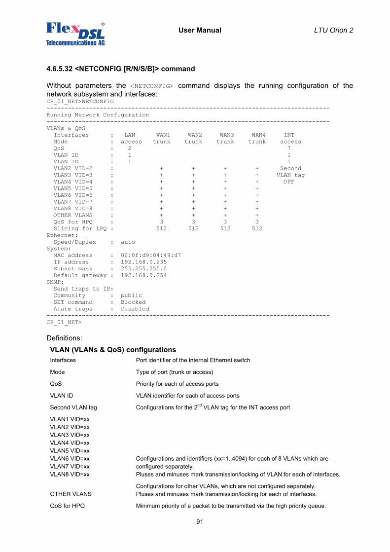
User Manual LTU Orion 2
91
4.6.5.32 <NETCONFIG [R/N/S/B]> command
Without parameters the <NETCONFIG> command displays the running configuration of the network subsystem and interfaces: CP_01_NET>NETCONFIG -------------------------------------------------------------------------------- Running Network Configuration -------------------------------------------------------------------------------- VLANs & QoS Interfaces : LAN WAN1 WAN2 WAN3 WAN4 INT Mode : access trunk trunk trunk trunk access QoS : 2 7 VLAN ID : 1 1 VLAN ID : 1 1 VLAN2 VID=2 : + + + + Second VLAN3 VID=3 : + + + + VLAN tag VLAN4 VID=4 : + + + + OFF VLAN5 VID=5 : + + + + VLAN6 VID=6 : + + + + VLAN7 VID=7 : + + + + VLAN8 VID=8 : + + + + OTHER VLANS : + + + + QoS for HPQ : 3 3 3 3 Slicing for LPQ : 512 512 512 512 Ethernet: Speed/Duplex : auto System: MAC address : 00:0f:d9:04:49:d7 IP address : 192.168.0.235 Subnet mask : 255.255.255.0 Default gateway : 192.168.0.254 SNMP: Send traps to IP: Community : public SET command : Blocked Alarm traps : Disabled -------------------------------------------------------------------------------- CP_01_NET> Definitions: VLAN (VLANs & QoS) configurations Interfaces Port identifier of the internal Ethernet switch
Mode Type of port (trunk or access)
QoS Priority for each of access ports
VLAN ID VLAN identifier for each of access ports
Second VLAN tag Configurations for the 2nd VLAN tag for the INT access port
VLAN1 VID=xx VLAN2 VID=xx VLAN3 VID=xx VLAN4 VID=xx VLAN5 VID=xx VLAN6 VID=xx VLAN7 VID=xx VLAN8 VID=xx
Configurations and identifiers (xx=1..4094) for each of 8 VLANs which are configured separately. Pluses and minuses mark transmission/locking of VLAN for each of interfaces.
OTHER VLANS Configurations for other VLANs, which are not configured separately. Pluses and minuses mark transmission/locking for each of interfaces.
QoS for HPQ Minimum priority of a packet to be transmitted via the high priority queue.
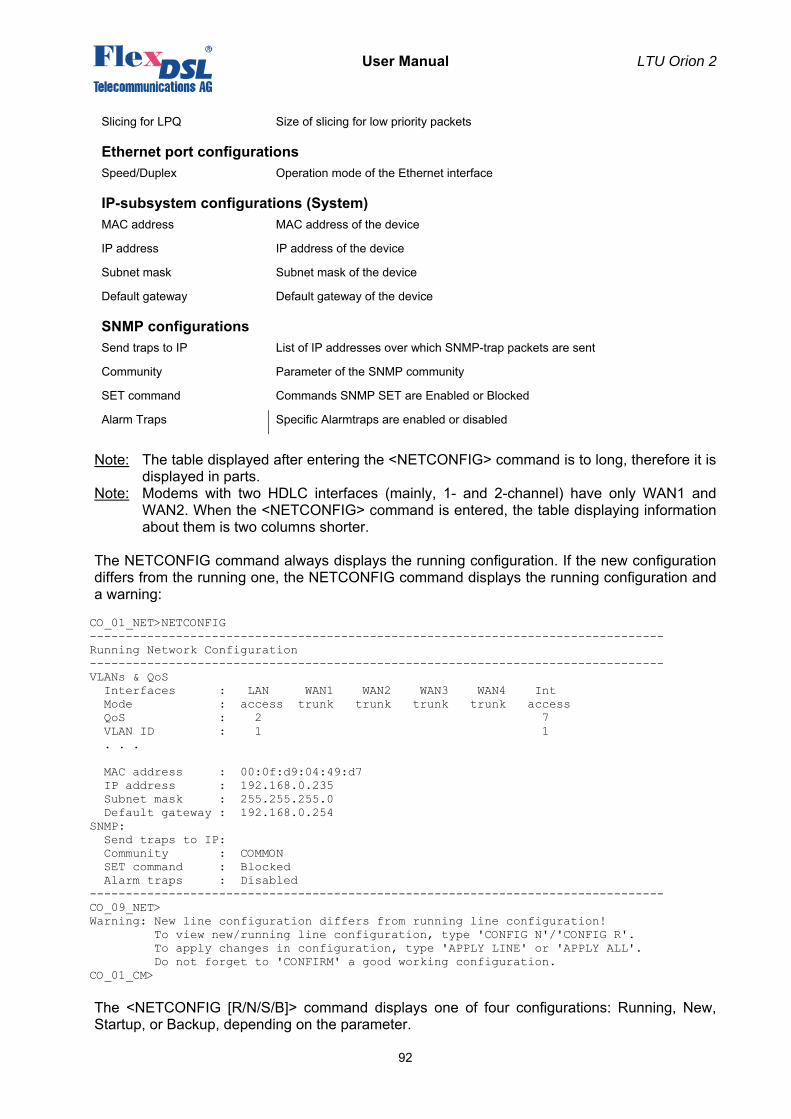
User Manual LTU Orion 2
92
Slicing for LPQ Size of slicing for low priority packets
Ethernet port configurations Speed/Duplex Operation mode of the Ethernet interface
IP-subsystem configurations (System) MAC address MAC address of the device
IP address IP address of the device
Subnet mask Subnet mask of the device
Default gateway Default gateway of the device
SNMP configurations Send traps to IP List of IP addresses over which SNMP-trap packets are sent
Community Parameter of the SNMP community
SET command Commands SNMP SET are Enabled or Blocked
Alarm Traps Specific Alarmtraps are enabled or disabled
Note: The table displayed after entering the <NETCONFIG> command is to long, therefore it is
displayed in parts. Note: Modems with two HDLC interfaces (mainly, 1- and 2-channel) have only WAN1 and
WAN2. When the <NETCONFIG> command is entered, the table displaying information about them is two columns shorter.
The NETCONFIG command always displays the running configuration. If the new configuration differs from the running one, the NETCONFIG command displays the running configuration and a warning: CO_01_NET>NETCONFIG -------------------------------------------------------------------------------- Running Network Configuration -------------------------------------------------------------------------------- VLANs & QoS Interfaces : LAN WAN1 WAN2 WAN3 WAN4 Int Mode : access trunk trunk trunk trunk access QoS : 2 7 VLAN ID : 1 1 . . . MAC address : 00:0f:d9:04:49:d7 IP address : 192.168.0.235 Subnet mask : 255.255.255.0 Default gateway : 192.168.0.254 SNMP: Send traps to IP: Community : COMMON SET command : Blocked Alarm traps : Disabled -------------------------------------------------------------------------------- CO_09_NET> Warning: New line configuration differs from running line configuration! To view new/running line configuration, type 'CONFIG N'/'CONFIG R'. To apply changes in configuration, type 'APPLY LINE' or 'APPLY ALL'. Do not forget to 'CONFIRM' a good working configuration. CO_01_CM> The <NETCONFIG [R/N/S/B]> command displays one of four configurations: Running, New, Startup, or Backup, depending on the parameter.
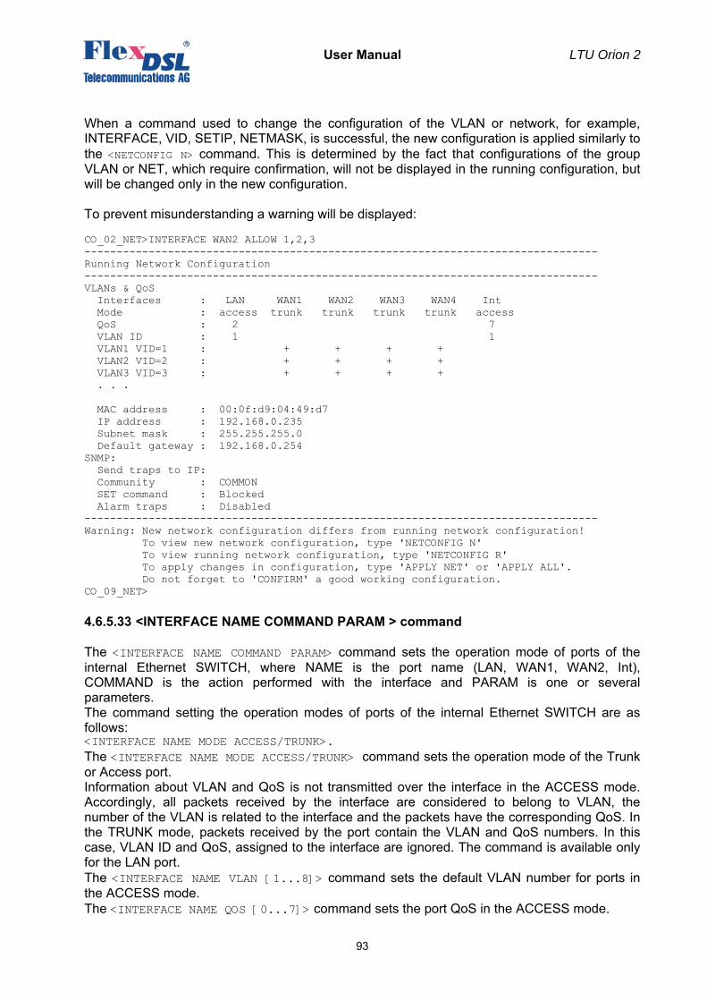
User Manual LTU Orion 2
93
When a command used to change the configuration of the VLAN or network, for example, INTERFACE, VID, SETIP, NETMASK, is successful, the new configuration is applied similarly to the <NETCONFIG N> command. This is determined by the fact that configurations of the group VLAN or NET, which require confirmation, will not be displayed in the running configuration, but will be changed only in the new configuration. To prevent misunderstanding a warning will be displayed: CO_02_NET>INTERFACE WAN2 ALLOW 1,2,3 -------------------------------------------------------------------------------- Running Network Configuration -------------------------------------------------------------------------------- VLANs & QoS Interfaces : LAN WAN1 WAN2 WAN3 WAN4 Int Mode : access trunk trunk trunk trunk access QoS : 2 7 VLAN ID : 1 1 VLAN1 VID=1 : + + + + VLAN2 VID=2 : + + + + VLAN3 VID=3 : + + + + . . . MAC address : 00:0f:d9:04:49:d7 IP address : 192.168.0.235 Subnet mask : 255.255.255.0 Default gateway : 192.168.0.254 SNMP: Send traps to IP: Community : COMMON SET command : Blocked Alarm traps : Disabled -------------------------------------------------------------------------------- Warning: New network configuration differs from running network configuration! To view new network configuration, type 'NETCONFIG N' To view running network configuration, type 'NETCONFIG R' To apply changes in configuration, type 'APPLY NET' or 'APPLY ALL'. Do not forget to 'CONFIRM' a good working configuration. CO_09_NET>
4.6.5.33 <INTERFACE NAME COMMAND PARAM > command
The <INTERFACE NAME COMMAND PARAM> command sets the operation mode of ports of the internal Ethernet SWITCH, where NAME is the port name (LAN, WAN1, WAN2, Int), COMMAND is the action performed with the interface and PARAM is one or several parameters. The command setting the operation modes of ports of the internal Ethernet SWITCH are as follows: <INTERFACE NAME MODE ACCESS/TRUNK>. The <INTERFACE NAME MODE ACCESS/TRUNK> command sets the operation mode of the Trunk or Access port. Information about VLAN and QoS is not transmitted over the interface in the ACCESS mode. Accordingly, all packets received by the interface are considered to belong to VLAN, the number of the VLAN is related to the interface and the packets have the corresponding QoS. In the TRUNK mode, packets received by the port contain the VLAN and QoS numbers. In this case, VLAN ID and QoS, assigned to the interface are ignored. The command is available only for the LAN port. The <INTERFACE NAME VLAN [1...8]> command sets the default VLAN number for ports in the ACCESS mode. The <INTERFACE NAME QOS [0...7]> command sets the port QoS in the ACCESS mode.
User Manual LTU Orion 2
94
The <INTERFACE NAME ALLOW VLAN-LIST> command sets the list of VLANs which are received by the port <INTERFACE NAME ALLOW VLAN- VLAN-LIST>. All units support 8 VLANs. The VID command is used to assign the VLAN name to its number. The List of VLANs, received by the interface is checked only in the TRUNK mode. In the ACCESS mode, only one VLAN (its default VLAN) is received by the interface although there can be added special MAC addresses for which another VLAN is assigned. For example: “INTERFACE LAN ALLOW 1, 4, 8” means that the LAN interface receives and transmits VLANs with names VLAN1, VLAN4, VLAN8. The <INTERFACE NAME QOSTHRESHOLD [0...7]> command sets the QoS threshold for interfaces WAN1 and WAN2 <INTERFACE NAME QOSTHRESHOLD [0...7]>. For example: “INTERFACE WAN1 QOSTHRESHOLD 4” means that all packets, whose QoS is greater or equal to the assigned ones, fall into the high priority (HP) queue. Otherwise, they fall into the low priority (LP) queue. Only WAN1 and WAN2 interfaces have the priority queues. If the HP queue contains at least one packet, it is this packet that will be transmitted despite the fact that the LP queue can contain a number of packets. MULTICAST and BROADCAST packets are subject to this rule as well. 0<=N<=7. The parameters of network interfaces set by using this command enter the group of VLAN configuration parameters, which require confirmation. That is why, after changing these parameters the operator needs to confirm changes. To apply changes, enter the Fault and Maintenance Menu (FMM) and use the <APPLY VLAN> command. As a result, changes in the VLAN group will be applied. Configurations being applied, use the <CONFIRM> command in the Fault and Maintenance Menu (FMM). If changes are not confirmed, configurations, which operated before using the <APPLY> command, will be used after the unit restart. If the <APPLY VLAN> command was sent from the Telnet session and during the changes in configurations this session was interrupted, the system waits the restoration of communication over Telnet for 5 minutes. If communication is not established within this time, the systems returns to configurations of the VLAN group written in the startup configuration.
4.6.5.34 <ETHSD 10/100/AUTO H/F [N=1..4]> command
The <ETHSD [10H/10F/100H/100F/AUTO] [N=1..4]> command sets the operating mode of the Ethernet port, where N is the number of the Ethernet port, 10/100 is the rate of 10 or 100 Mbit/s, F is full duplex and H is half duplex. The <ETHSD AUTO> command activates the rate and duplex autodetection. For devices with one Ethernet interface, the command is as follows: CO_09_CM>ETHSD 10H 1 CO_09_CM>ETHSD AUTO 2
4.6.5.35 <SLICING SIZE> command
The <SLICING SIZE> command sets the low priority packet size. The transmission of packets of the maximum size (for Ethernet) over low rate interface (WAN1 – WAN4) is time consuming. This can result in delays in the transmission of high priority packets. Therefore, the long low priority packets should be fragmented before transmitting them via WAN1 – WAN4 interfaces. The <SLICING SIZE> command sets the maximum size of packets in bytes. The SIZE parameter can take the following values: 64/96/128/256/512/1024/OFF.
4.6.5.36 <SETIP X.X.X.X> command
The <SETIP A.B.C.D> command sets the IP-address of the modem. The parameter A, B, C and D can take values from 0 to 255 (note that neither address of the network nor the address of the node can be equal to 0, or to 255).
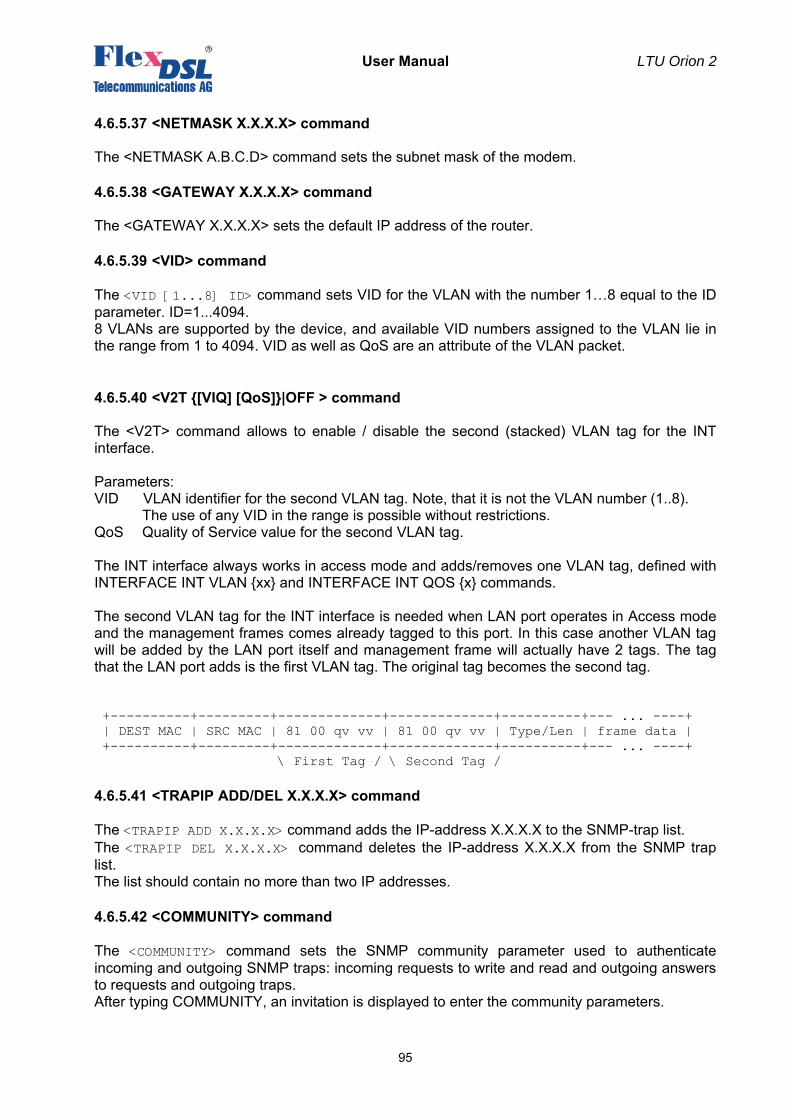
User Manual LTU Orion 2
95
4.6.5.37 <NETMASK X.X.X.X> command
The <NETMASK A.B.C.D> command sets the subnet mask of the modem.
4.6.5.38 <GATEWAY X.X.X.X> command
The <GATEWAY X.X.X.X> sets the default IP address of the router.
4.6.5.39 <VID> command
The <VID [1...8] ID> command sets VID for the VLAN with the number 1…8 equal to the ID parameter. ID=1...4094. 8 VLANs are supported by the device, and available VID numbers assigned to the VLAN lie in the range from 1 to 4094. VID as well as QoS are an attribute of the VLAN packet.
4.6.5.40 <V2T {[VIQ] [QoS]}|OFF > command
The <V2T> command allows to enable / disable the second (stacked) VLAN tag for the INT interface. Parameters: VID VLAN identifier for the second VLAN tag. Note, that it is not the VLAN number (1..8). The use of any VID in the range is possible without restrictions. QoS Quality of Service value for the second VLAN tag. The INT interface always works in access mode and adds/removes one VLAN tag, defined with INTERFACE INT VLAN {xx} and INTERFACE INT QOS {x} commands. The second VLAN tag for the INT interface is needed when LAN port operates in Access mode and the management frames comes already tagged to this port. In this case another VLAN tag will be added by the LAN port itself and management frame will actually have 2 tags. The tag that the LAN port adds is the first VLAN tag. The original tag becomes the second tag. +----------+---------+-------------+-------------+----------+--- ... ----+ | DEST MAC | SRC MAC | 81 00 qv vv | 81 00 qv vv | Type/Len | frame data | +----------+---------+-------------+-------------+----------+--- ... ----+ \ First Tag / \ Second Tag /
4.6.5.41 <TRAPIP ADD/DEL X.X.X.X> command
The <TRAPIP ADD X.X.X.X> command adds the IP-address X.X.X.X to the SNMP-trap list. The <TRAPIP DEL X.X.X.X> command deletes the IP-address X.X.X.X from the SNMP trap list. The list should contain no more than two IP addresses.
4.6.5.42 <COMMUNITY> command
The <COMMUNITY> command sets the SNMP community parameter used to authenticate incoming and outgoing SNMP traps: incoming requests to write and read and outgoing answers to requests and outgoing traps. After typing COMMUNITY, an invitation is displayed to enter the community parameters.
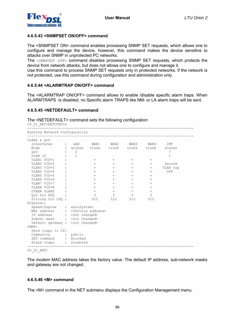
User Manual LTU Orion 2
96
4.6.5.43 <SNMPSET ON/OFF> command
The <SNMPSET ON> command enables processing SNMP SET requests, which allows one to configure and manage the device, however, this command makes the device sensitive to attacks over SNMP in unprotected PC networks. The <SNMPSET OFF> command disables processing SNMP SET requests, which protects the device from network attacks, but does not allows one to configure and manage it. Use this command to process SNMP SET requests only in protected networks. If the network is not protected, use this command during configuration and administration only.
4.6.5.44 <ALARMTRAP ON/OFF> command
The <ALARMTRAP ON/OFF> command allows to enable /disable specific alarm traps. When ALARMTRAPS is disabled, no Specific alarm TRAPS like NM- or LA alarm traps will be sent.
4.6.5.45 <NETDEFAULT> command
The <NETDEFAULT> command sets the following configuration: CP_01_NET>NETCONFIG -------------------------------------------------------------------------------- Running Network Configuration -------------------------------------------------------------------------------- VLANs & QoS Interfaces : LAN WAN1 WAN2 WAN3 WAN4 INT Mode : access trunk trunk trunk trunk access QoS : 2 7 VLAN ID : 1 1 VLAN1 VID=1 : + + + + VLAN2 VID=2 : + + + + Second VLAN3 VID=3 : + + + + VLAN tag VLAN4 VID=4 : + + + + OFF VLAN5 VID=5 : + + + + VLAN6 VID=6 : + + + + VLAN7 VID=7 : + + + + VLAN8 VID=8 : + + + + OTHER VLANS : + + + + QoS for HPQ : 3 3 3 3 Slicing for LPQ : 512 512 512 512 Ethernet: Speed/Duplex : autoSystem: MAC address : <factory address> IP address : <not changed> Subnet mask : <not changed> Default gateway : <not changed> SNMP: Send traps to IP: Community : public SET command : Blocked Alarm traps : Disabled -------------------------------------------------------------------------------- CO_01_NET> The modem MAC address takes the factory value. The default IP address, sub-network masks and gateway are not changed.
4.6.5.46 <M> command
The <M> command in the NET submenu displays the Configuration Management menu.
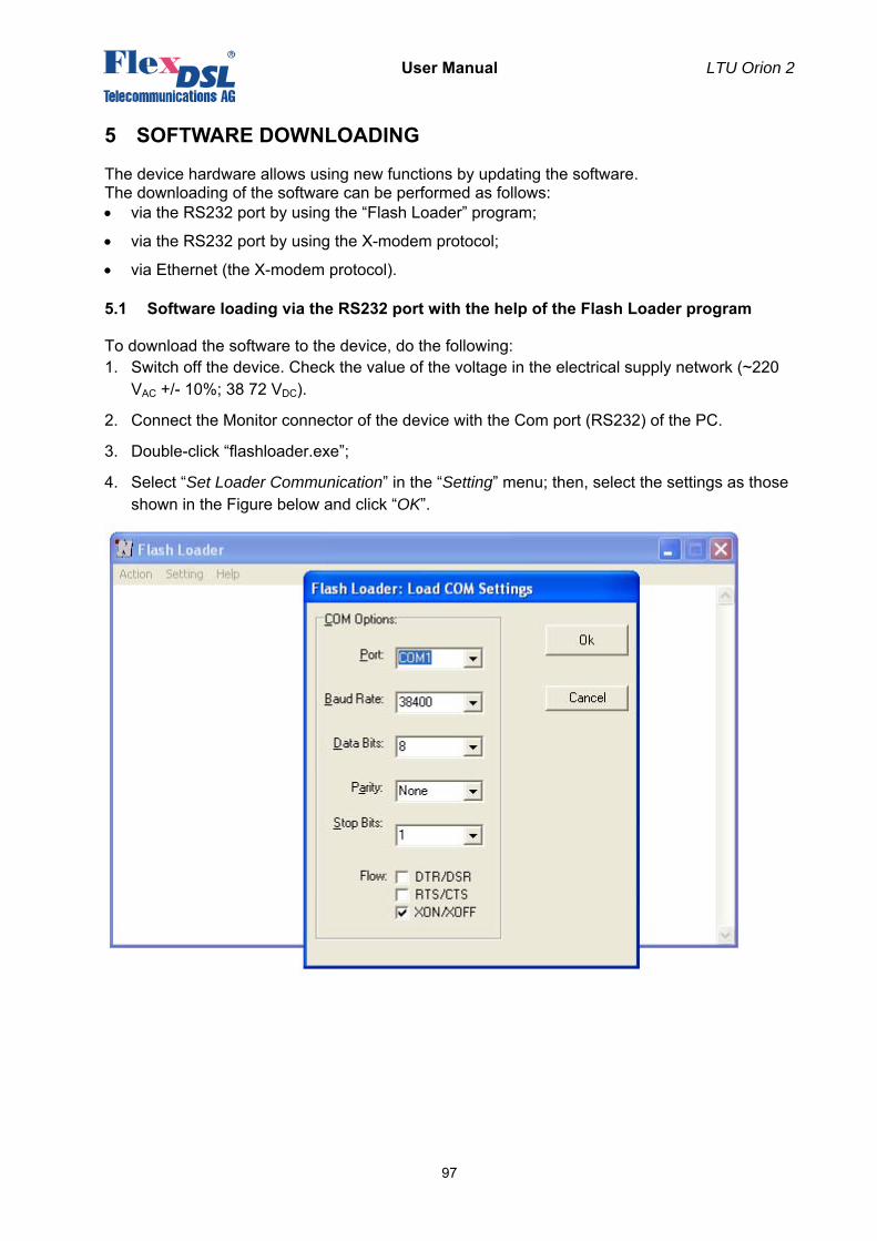
User Manual LTU Orion 2
97
5 SOFTWARE DOWNLOADING
The device hardware allows using new functions by updating the software. The downloading of the software can be performed as follows: • via the RS232 port by using the “Flash Loader” program;
• via the RS232 port by using the X-modem protocol;
• via Ethernet (the X-modem protocol).
5.1 Software loading via the RS232 port with the help of the Flash Loader program
To download the software to the device, do the following: 1. Switch off the device. Check the value of the voltage in the electrical supply network (~220
VAC +/- 10%; 38 72 VDC).
2. Connect the Monitor connector of the device with the Com port (RS232) of the PC.
3. Double-click “flashloader.exe”;
4. Select “Set Loader Communication” in the “Setting” menu; then, select the settings as those shown in the Figure below and click “OK”.
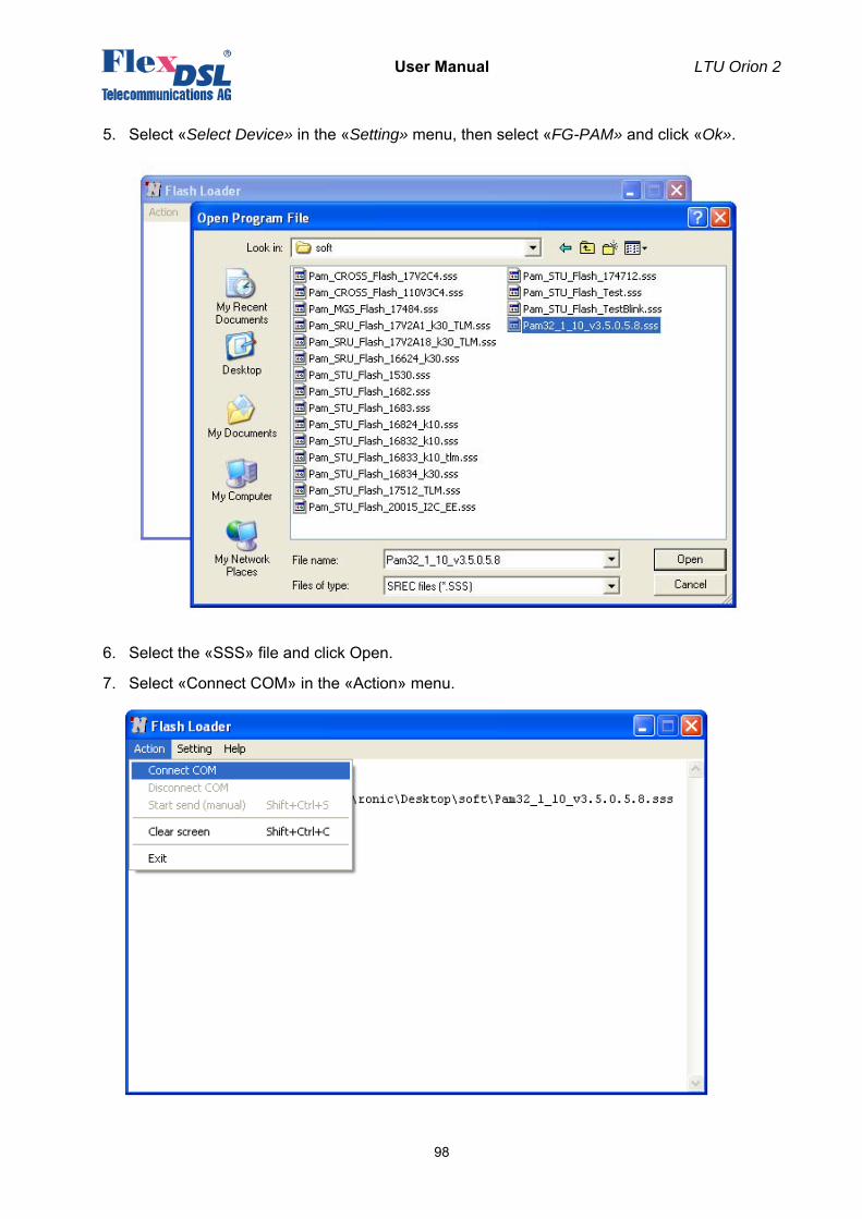
User Manual LTU Orion 2
98
5. Select «Select Device» in the «Setting» menu, then select «FG-PAM» and click «Ok».
6. Select the «SSS» file and click Open.
7. Select «Connect COM» in the «Action» menu.
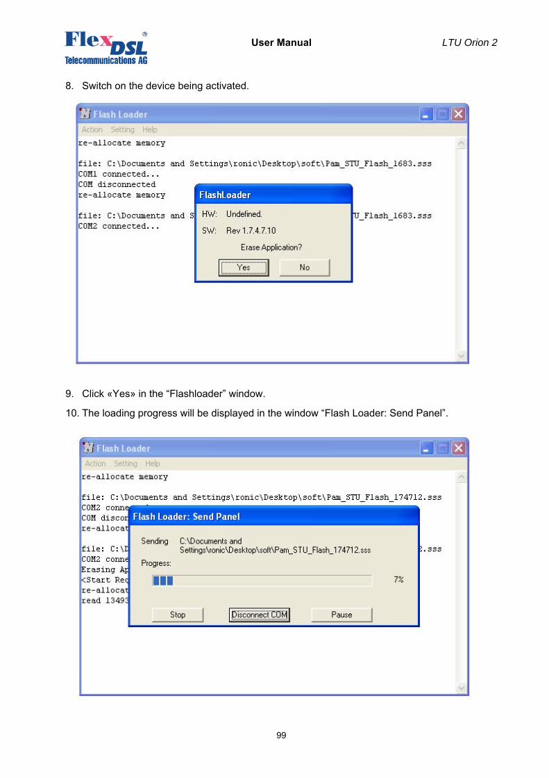
User Manual LTU Orion 2
99
8. Switch on the device being activated.
9. Click «Yes» in the “Flashloader” window.
10. The loading progress will be displayed in the window “Flash Loader: Send Panel”.
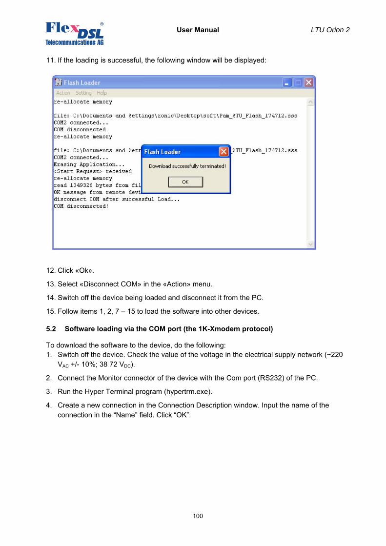
User Manual LTU Orion 2
100
11. If the loading is successful, the following window will be displayed:
12. Click «Ok».
13. Select «Disconnect COM» in the «Action» menu.
14. Switch off the device being loaded and disconnect it from the PC.
15. Follow items 1, 2, 7 – 15 to load the software into other devices.
5.2 Software loading via the COM port (the 1K-Xmodem protocol)
To download the software to the device, do the following: 1. Switch off the device. Check the value of the voltage in the electrical supply network (~220
VAC +/- 10%; 38 72 VDC).
2. Connect the Monitor connector of the device with the Com port (RS232) of the PC.
3. Run the Hyper Terminal program (hypertrm.exe).
4. Create a new connection in the Connection Description window. Input the name of the connection in the “Name” field. Click “OK”.
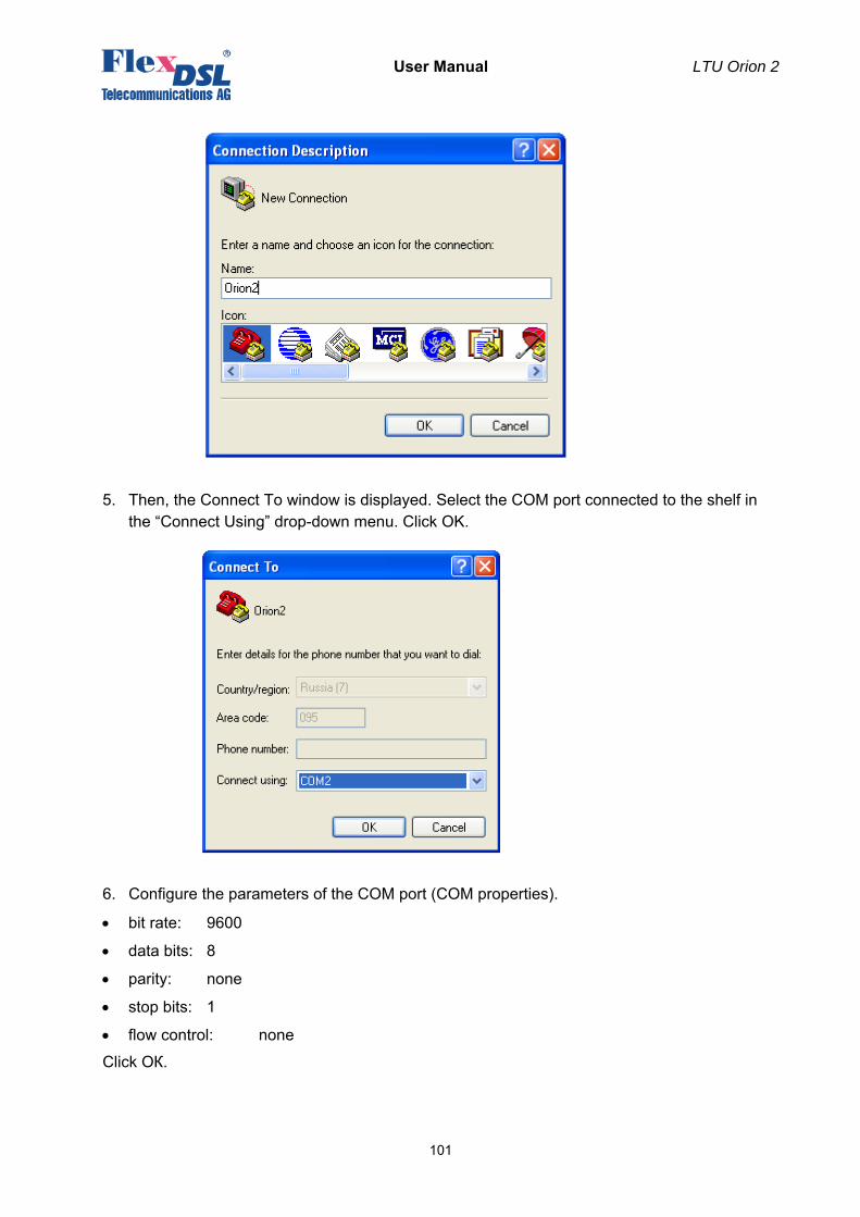
User Manual LTU Orion 2
101
5. Then, the Connect To window is displayed. Select the COM port connected to the shelf in the “Connect Using” drop-down menu. Click OK.
6. Configure the parameters of the COM port (COM properties).
• bit rate: 9600
• data bits: 8
• parity: none
• stop bits: 1
• flow control: none
Click ОК.
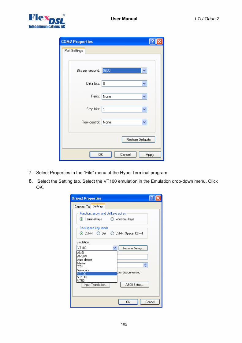
User Manual LTU Orion 2
102
7. Select Properties in the “File” menu of the HyperTerminal program.
8. Select the Setting tab. Select the VT100 emulation in the Emulation drop-down menu. Click OK.
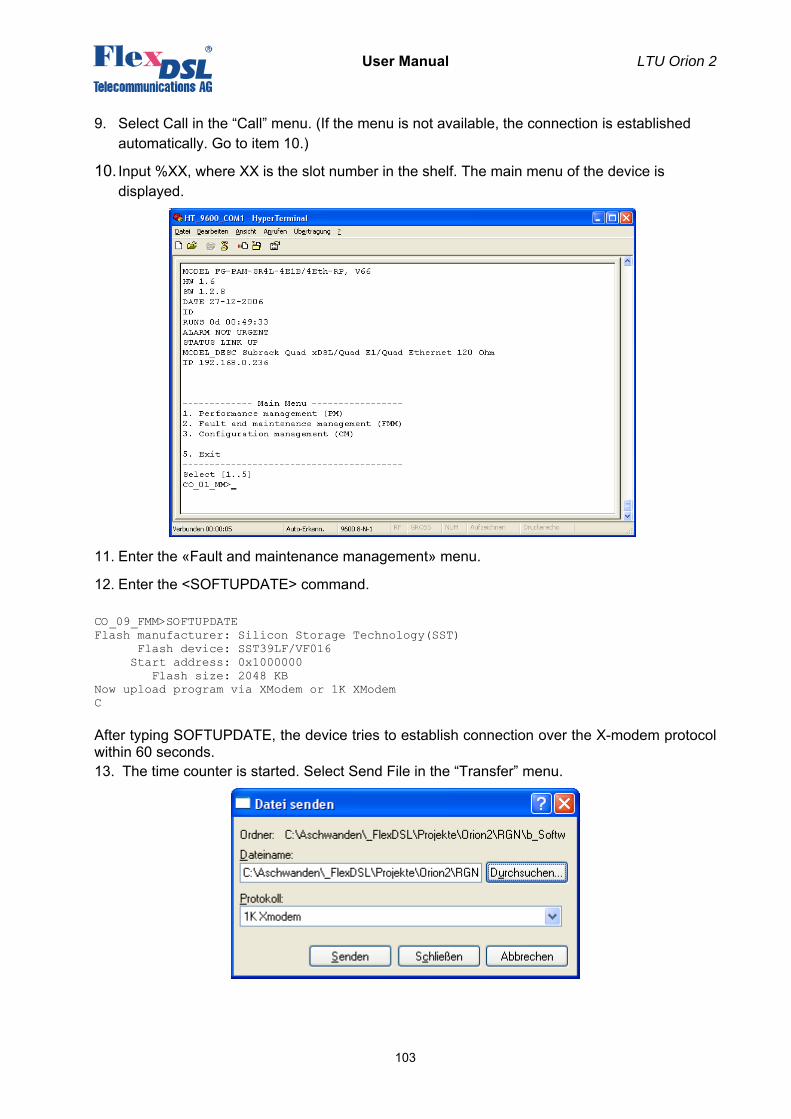
User Manual LTU Orion 2
103
9. Select Call in the “Call” menu. (If the menu is not available, the connection is established automatically. Go to item 10.)
10. Input %XX, where XX is the slot number in the shelf. The main menu of the device is displayed.
11. Enter the «Fault and maintenance management» menu.
12. Enter the <SOFTUPDATE> command. CO_09_FMM>SOFTUPDATE Flash manufacturer: Silicon Storage Technology(SST) Flash device: SST39LF/VF016 Start address: 0x1000000 Flash size: 2048 KB Now upload program via XModem or 1K XModem C After typing SOFTUPDATE, the device tries to establish connection over the X-modem protocol within 60 seconds. 13. The time counter is started. Select Send File in the “Transfer” menu.
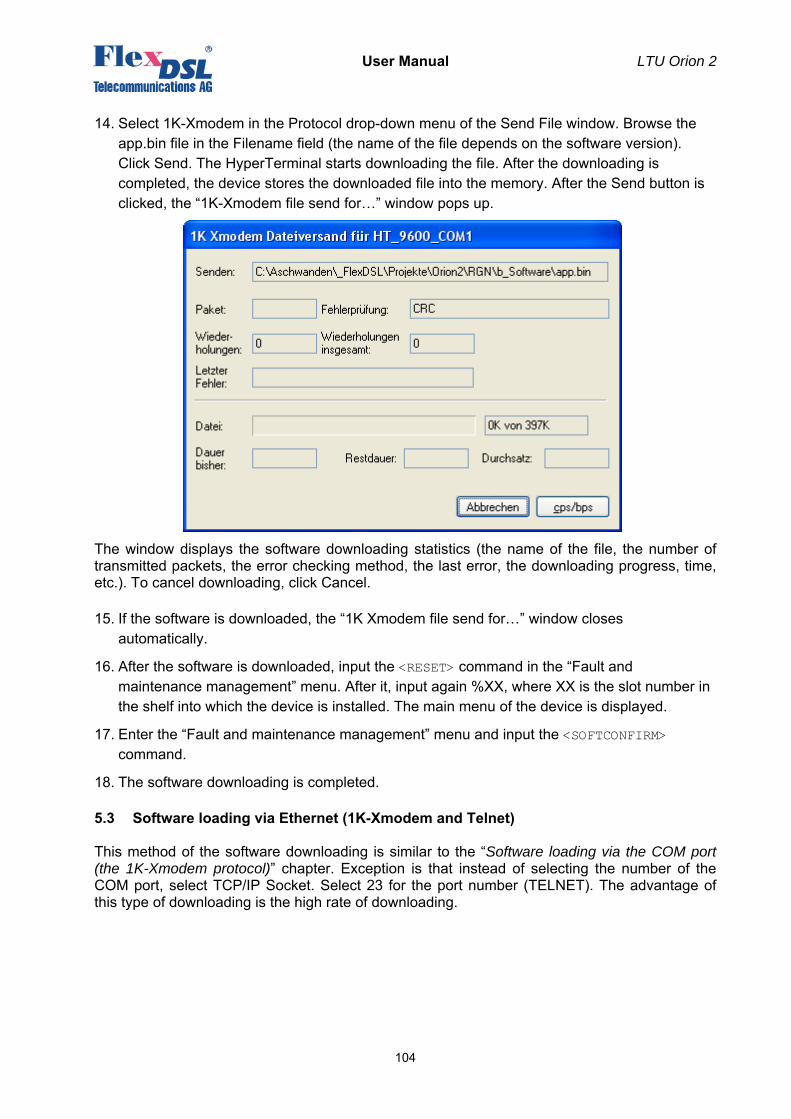
User Manual LTU Orion 2
104
14. Select 1K-Xmodem in the Protocol drop-down menu of the Send File window. Browse the app.bin file in the Filename field (the name of the file depends on the software version). Click Send. The HyperTerminal starts downloading the file. After the downloading is completed, the device stores the downloaded file into the memory. After the Send button is clicked, the “1K-Xmodem file send for…” window pops up.
The window displays the software downloading statistics (the name of the file, the number of transmitted packets, the error checking method, the last error, the downloading progress, time, etc.). To cancel downloading, click Cancel. 15. If the software is downloaded, the “1K Xmodem file send for…” window closes
automatically.
16. After the software is downloaded, input the <RESET> command in the “Fault and maintenance management” menu. After it, input again %XX, where XX is the slot number in the shelf into which the device is installed. The main menu of the device is displayed.
17. Enter the “Fault and maintenance management” menu and input the <SOFTCONFIRM> command.
18. The software downloading is completed.
5.3 Software loading via Ethernet (1K-Xmodem and Telnet)
This method of the software downloading is similar to the “Software loading via the COM port (the 1K-Xmodem protocol)” chapter. Exception is that instead of selecting the number of the COM port, select TCP/IP Socket. Select 23 for the port number (TELNET). The advantage of this type of downloading is the high rate of downloading.
User Manual LTU Orion 2
105
6 SERVICE INSTRUCTIONS
6.1 General requirements
• Before unpacking, check if the packing box is intact and if the equipment model is consistent with that specified in the purchase contract.
• Before starting operating the device, read carefully the present technical description and service instructions. Remember that the guarantee and the free-of-charge repair will not be granted under the following conditions:
a) if the device or any of its parts fails due to improper installation, testing or operation. b) demages resulting from:
1) misuse and improper installation, including but not limited to: - to use the product for its normal purpose or in accordance with the instructions on the proper use and maintenance, - installation and use of the product in a manner inconsistent with technical or safety standards in force in the country where it is used, as well as the connection of the device to the power supply source, other than required by the technical or safety standards, 2) maintenance or repair performed by unauthorized service centers and dealers; 3) operation of a malfunctioning device; 4) accidents, lightning strokes, flooding, water, fire, improper ventilation, voltage drops, ingress of moisture and insects inside the equipment as well as other reasons, for example, electromagnetic and other interferences which are beyond the Supplier control and do not correspond to technical conditions; 5) transportation except for the cases, when shipping is performed by an authorized dealer or a service center; 7) defects of the system into which this product is incorporated.
• The equipment should be powered from a primary DC source (38 … 72 V) with the grounded “+”.
• Environment requirements:
Temperature: from -5 to +45 °C; Relative air humidity: from 5% to 85% at +25 °C.
• It is strictly prohibited:
a) to alter, delete, remove or make illegible the serial number of the device; b) to adapt, adjust and change the equipment in order to improve it or extend its
applications without the prior written consent of the Supplier; c) to alter or adjust the equipment without the consent of the Supplier.
User Manual LTU Orion 2
106
6.2 Evaluation of the quality of the digital channel and operation parameters
The quality of the digital channel is evaluated by: • The ITU-T G.826 error performance monitoring of a DSL link is performed according to ITU-
T Rec. G.704. The evaluation of the G.826 error performance parameters is based on CRC (Cyclic Redundancy Check) error detection. On the xDSL side, six CRC6 check bits are generated per xDSL frame. CRC6 errors are used by the software to count the block errors of the xDSL channel and to evaluate its error performance according to ITU-T Rec. G.826. The G826 command is used to display the G.826 statistics.
• The Noise Margin performance monitoring.
The Noise Margin (NM) provides qualitative performance information of a specific link. The NM command is used to activate this test. This parameter is calculated according to G.991.2 and is an efficient tool for determining the qualitative performance of an xDSL link. The recommended NM valus should be no less than 8 dB. This value provides the necessary reserve of the signal/noise margin. It is recommended to perform the ITU-T G.826 test regularly. It is recommended to perform the Noise Margin performance monitoring during acceptance tests and in case the system operates unstably. The test is used to locate the damaged cable segment. In addition, it is also recommended to monitor regularly the quality of data transmission over E1 interfaces. On the E1 side, four CRC4 check bits are generated per sub-multiframe (SMF) and compared with the corresponding bits of the next SMF. If they do not match, the CRC4 error counter is incremented. The G826 command is used to display the G.826 statistics. The correctness of configurations of network interfaces and operability can be checked by using loopback tests (LOOP1) and G.826 statistics of E1 interfaces. If LOOP1 is activated on this network interface and the G826 statistics displays errors, a conclusion can be made that the E1 network interface of the FlexDSL Orion 2 system is configured improperly or malfunctions.

User Manual LTU Orion 2
107
7 APPENDICES
7.1 Example 1 of configuration of Orion 2 devices
An example of organization of a data transmission system with the help of Orion 2 devices is presented below:
Note: The PABX (ATS in the figure) supports the CRC4 mode, if this mode is enabled. Before setting IP addresses of the system devices, make sure that these IP addresses are not used by other devices connected to the system. (Enter the PING command to check IP addresses in all networks connected to the FlexDSL Orion2 equipment).
We present settings of the devices below. If all these settings are configured as shown below, the user will construct a data transmission system, which will operate normally. The idea is as follows: the default settings are deleted on all the devices, then the MASTER/SLAVE mode is enabled on the modem, the network settings are configured (IP address, default subnet mask and default gateway) and finally, these settings are applied and then are written in the EEPROM.
7.1.1 Configuration of the FlexDSL Orion 2 device at the Central Office premises.
System configuration (Configuration Management menu): <DEFAULT EVERYTHING> – enable default settings
<POWER ON> – switch on remote powering (the modes are activated by jumpers on the main board)
Line interface configuration (Configuration Management menu): <MASTER ON> – enable the Master mode
Configuration of the internal Ethernet switch (Network Management submenu):
<SETIP 10.0.2.200> – set the IP-address of the device (depends on the configuration of the network)
<NETMASK 255.0.0.0>
– set the subnet mask (this value is the same as in the connected Ethernet network)
<GATEWAY 10.0.0.101>
– set the default gateway (this value is the same as in the connected Ethernet network)
Application of all configurations (Fault And Maintenance Management menu):
Orion2 LTU
RGNo2(remote power)
Orion2NTU
SHDSL SHDSL
FG-PAM-SRL-2E1B/4Eth-RP, V9 FG-PAM-SA2N-2E1B/Eth, V8
FG-PAM-RGN-Eth-PL, V8G.703 (E1-1)
Repeater Point
G.703 (E1-2)
ATS
G.703 (E1-1)
G.703 (E1-2)
ATS
Ethernet Network
ETH1
Ethernet Network
Customer Premises Equipment
Central Office
Ethernet Network
User Manual LTU Orion 2
108
<APPLY ALL> – apply all configurations (written in the running configuration)
Confirmation of all configurations (Fault And Maintenance Management menu): <CONFIRM> – confirm all configurations (written in the startup configuration)
7.1.2 Configuration of the FlexDSL Orion 2 device at the Customer Premises.
System configuration (Configuration Management menu): <DEFAULT EVERYTHING> – enable default settings
Line interface configuration (Configuration Management menu): <MASTER OFF> – enable the Slave mode
Configuration of the internal Ethernet switch (Network Management submenu):
<SETIP 10.0.2.201> – set the IP-address of the device (depends on the configuration of the network)
<NETMASK 255.0.0.0>
– set the subnet mask (this value is the same as in the connected Ethernet network)
<GATEWAY 10.0.0.101>
– set the default gateway (this value is the same as in the connected Ethernet network)
Application of all configurations (Fault And Maintenance Management menu): <APPLY ALL> – apply all configurations (written in the running configuration)
Confirmation of all configurations (Fault And Maintenance Management menu): <CONFIRM> – confirm all configurations (written in the startup configuration)
7.1.3 Configuration of the FlexDSL Orion 2 regenerator at the Regenerator Point.
System configuration (Configuration Management menu): <DEFAULT EVERYTHING> – enable default settings
Line interface configuration (Configuration Management menu): <MASTER AUTO> – enable automatic detection of the Master/Slave mode
<BASERATE AUTO> – enable automatic detection of the line rate Configuration of the internal Ethernet switch (Network Management submenu):
<SETIP 10.0.2.202> – set the IP address of the device (depends on the configuration of the connected network)
<NETMASK 255.0.0.0>
– set the subnet mask (this value is the same as in the connected Ethernet network)
<GATEWAY 10.0.0.101>
– set the default gateway (this value is the same as in the connected Ethernet network)
Application of all configurations (Fault And Maintenance Management menu): <APPLY ALL> – apply all configurations (written in the running configuration)
Confirmation of all configurations (Fault And Maintenance Management menu): <CONFIRM> – confirm all configurations (written in the startup configuration)
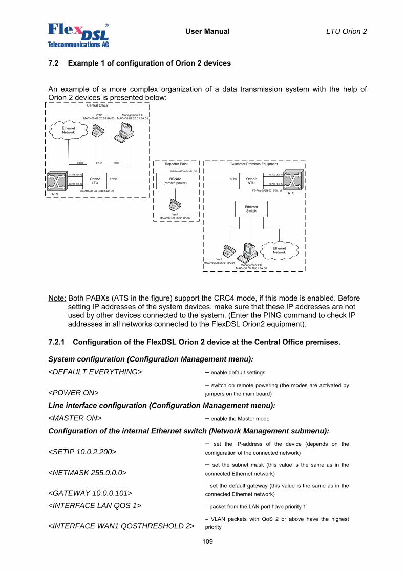
User Manual LTU Orion 2
109
7.2 Example 1 of configuration of Orion 2 devices
An example of a more complex organization of a data transmission system with the help of Orion 2 devices is presented below:
Note: Both PABXs (ATS in the figure) support the CRC4 mode, if this mode is enabled. Before
setting IP addresses of the system devices, make sure that these IP addresses are not used by other devices connected to the system. (Enter the PING command to check IP addresses in all networks connected to the FlexDSL Orion2 equipment).
7.2.1 Configuration of the FlexDSL Orion 2 device at the Central Office premises.
System configuration (Configuration Management menu): <DEFAULT EVERYTHING> – enable default settings
<POWER ON> – switch on remote powering (the modes are activated by jumpers on the main board)
Line interface configuration (Configuration Management menu): <MASTER ON> – enable the Master mode
Configuration of the internal Ethernet switch (Network Management submenu):
<SETIP 10.0.2.200> – set the IP-address of the device (depends on the configuration of the connected network)
<NETMASK 255.0.0.0> – set the subnet mask (this value is the same as in the connected Ethernet network)
<GATEWAY 10.0.0.101> – set the default gateway (this value is the same as in the connected Ethernet network)
<INTERFACE LAN QOS 1> – packet from the LAN port have priority 1
<INTERFACE WAN1 QOSTHRESHOLD 2> – VLAN packets with QoS 2 or above have the highest priority
Orion2 LTU
RGNo2(remote power)
Orion2NTU
SHDSL SHDSL
FG-PAM-SRL-2E1B/4Eth-RP, V9 FG-PAM-SA2N-2E1B/Eth, V8
FG-PAM-RGN-Eth-PL, V8G.703 (E1-1)
Management PCMAC=00:09:26:01:8A:05
VoIPMAC=00:09:26:01:8A:03
Ethernet Switch
Management PCMAC=00:09:26:01:8A:06
VoIPMAC=00:09:26:01:8A:04
Repeater Point
G.703 (E1-2)
ATS
G.703 (E1-1)
G.703 (E1-2)
ATS
Ethernet Network
ETH1 ETH2 ETH3
VoIPMAC=00:09:26:01:8A:07
Ethernet Network
Customer Premises Equipment
Central Office
User Manual LTU Orion 2
110
<INTERFACE INT VLAN 3> – packets of the internal management port belong to VLAN 3
<INTERFACE INT QOS 2> – packets from the LAN port have priority 0
<INTERFACE WAN1 ALLOW 1,2,3> – transmit packets of VLAN 1,2,3 over the WAN1 port
Application of all configurations (Fault And Maintenance Management menu):
<APPLY ALL> – apply all configurations (written in the running configuration)
Confirmation of all configurations (Fault And Maintenance Management menu):
<CONFIRM> – confirm all configurations (written in the startup configuration)
7.2.2 Configuration of the FlexDSL Orion 2 device at the Customer Premises.
System configuration (Configuration Management menu): <DEFAULT EVERYTHING> – enable default settings
Line interface configuration (Configuration Management menu): <MASTER OFF> – enable the Slave mode
Configuration of the internal Ethernet switch (Network Management submenu):
<SETIP 10.0.2.201> – set the IP address of the device (depends on the configuration of the connected network)
<NETMASK 255.0.0.0> – set the subnet mask (this value is the same as in the connected Ethernet network)
<GATEWAY 10.0.0.101> – set the default gateway (this value is the same as in the connected Ethernet network)
<INTERFACE LAN QOS 1> – packet from the LAN port have priority 1
<INTERFACE WAN1 QOSTHRESHOLD 2> – VLAN packets with QoS 2 or above have the highest priority
<INTERFACE INT VLAN 3> – packets of the internal management port belong to VLAN 3
<INTERFACE INT QOS 2> – packets from the LAN port have priority 0
<INTERFACE WAN1 ALLOW 1,2,3> – transmit packets of VLAN 1,2,3 over the WAN1 port
Application of all configurations (Fault And Maintenance Management menu):
<APPLY ALL> – apply all configurations (written in the running configuration)
Confirmation of all configurations (Fault And Maintenance Management menu):
<CONFIRM> – confirm all configurations (written in the startup configuration)
User Manual LTU Orion 2
111
7.2.3 Configuration of the FlexDSL Orion 2 regenerator at the Regenerator Point.
System configuration (Configuration Management menu): <DEFAULT EVERYTHING> – enable default settings
Line interface configuration (Configuration Management menu): <MASTER AUTO> – enable automatic detection of the Master/Slave mode
<BASERATE AUTO> – enable automatic detection of the line rate Configuration of the internal Ethernet switch (Network Management submenu):
<SETIP 10.0.2.202> – set the IP address of the device (depends on the configuration of the connected network)
<NETMASK 255.0.0.0> – set the subnet mask (this value is the same as in the connected Ethernet network)
<GATEWAY 10.0.0.101> – set the default gateway (this value is the same as in the connected Ethernet network)
<INTERFACE LAN QOS 1> – packet from the LAN port have priority 1
<INTERFACE WAN1 QOSTHRESHOLD 2> – VLAN packets with QoS 2 or above have the highest priority
<INTERFACE INT VLAN 3> – packets of the internal management port belong to VLAN 3
<INTERFACE INT QOS 2> – packets from the LAN port have priority 0
<INTERFACE WAN1 ALLOW 1,2,3> – transmit packets of VLAN 1,2,3 over the WAN1 port
Application of all configurations (Fault And Maintenance Management menu): <APPLY ALL> – apply all configurations (written in the running configuration)
Confirmation of all configurations (Fault And Maintenance Management menu):
<CONFIRM> – confirm all configurations (written in the startup configuration)
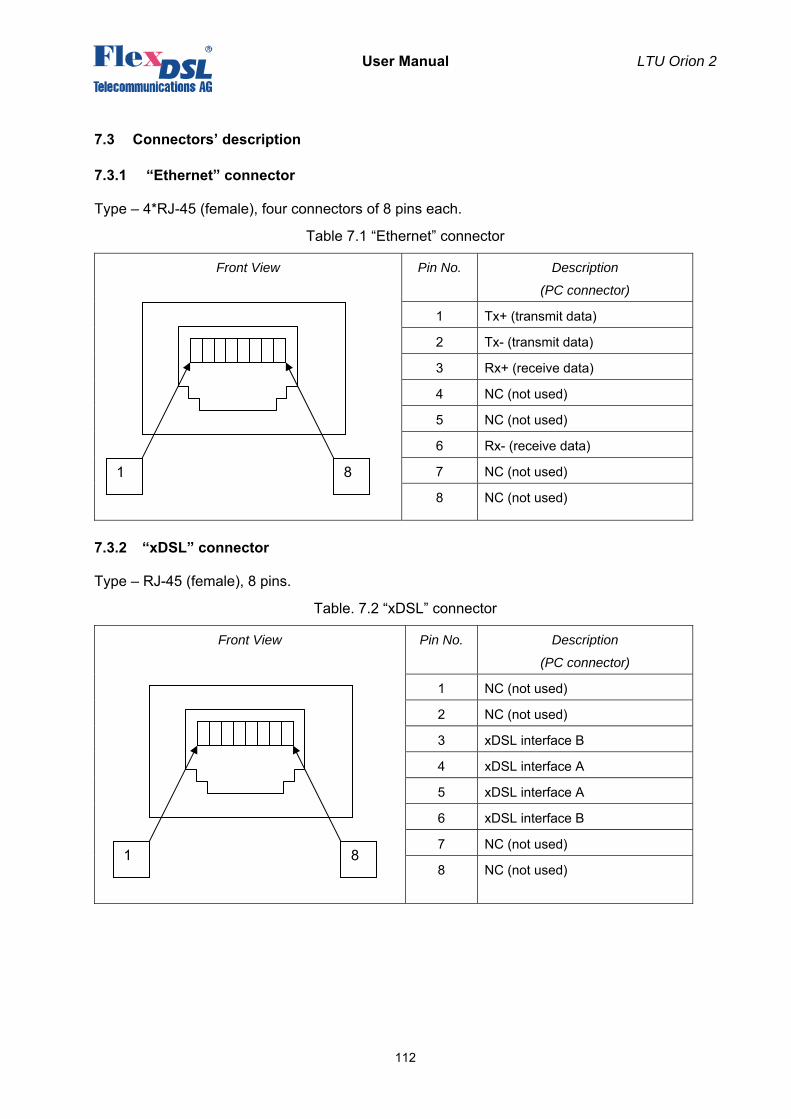
User Manual LTU Orion 2
112
7.3 Connectors’ description
7.3.1 “Ethernet” connector
Type – 4*RJ-45 (female), four connectors of 8 pins each.
Table 7.1 “Ethernet” connector
Front View Pin No. Description
(PC connector)
1 Tx+ (transmit data)
2 Tx- (transmit data)
3 Rx+ (receive data)
4 NC (not used)
5 NC (not used)
6 Rx- (receive data)
7 NC (not used)
8 NC (not used)
7.3.2 “xDSL” connector
Type – RJ-45 (female), 8 pins.
Table. 7.2 “xDSL” connector
Front View Pin No. Description
(PC connector)
1 NC (not used)
2 NC (not used)
3 xDSL interface B
4 xDSL interface A
5 xDSL interface A
6 xDSL interface B
7 NC (not used)
8 NC (not used)
1 8
1 8
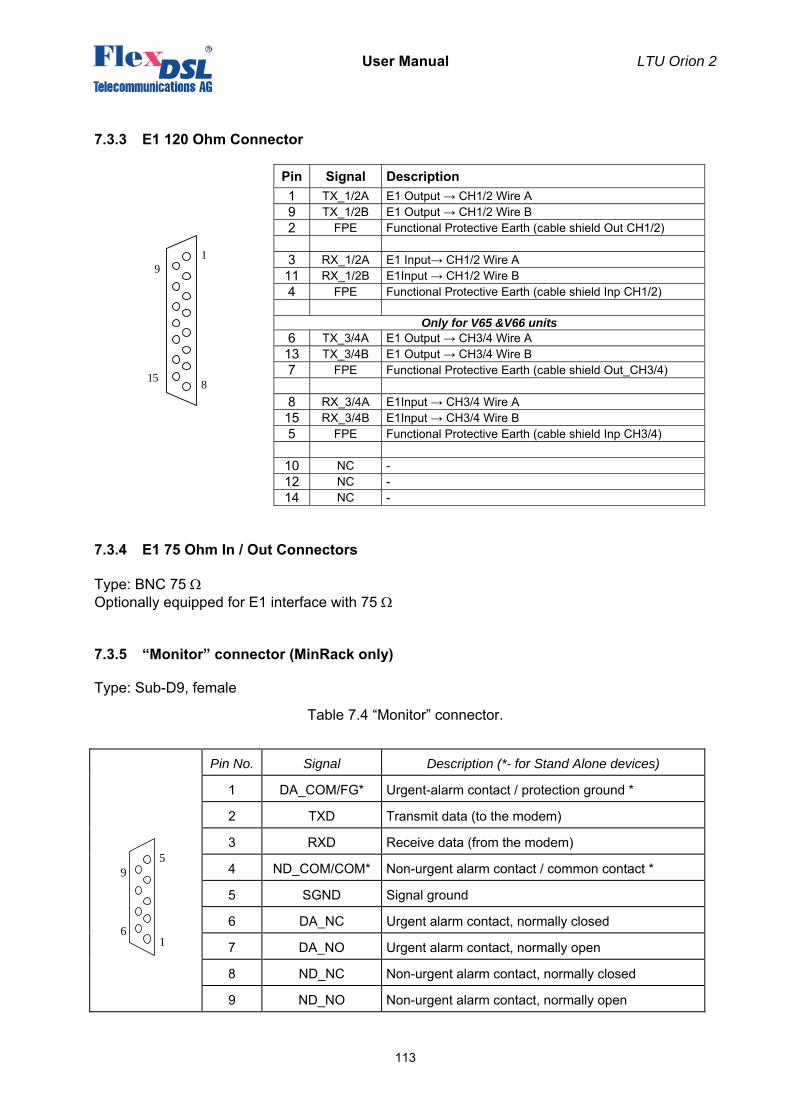
User Manual LTU Orion 2
113
7.3.3 E1 120 Ohm Connector
1
8
9
15
Pin Signal Description 1 TX_1/2A E1 Output → CH1/2 Wire A 9 TX_1/2B E1 Output → CH1/2 Wire B 2 FPE Functional Protective Earth (cable shield Out CH1/2) 3 RX_1/2A E1 Input→ CH1/2 Wire A 11 RX_1/2B E1Input → CH1/2 Wire B 4 FPE Functional Protective Earth (cable shield Inp CH1/2)
Only for V65 &V66 units 6 TX_3/4A E1 Output → CH3/4 Wire A 13 TX_3/4B E1 Output → CH3/4 Wire B 7 FPE Functional Protective Earth (cable shield Out_CH3/4) 8 RX_3/4A E1Input → CH3/4 Wire A 15 RX_3/4B E1Input → CH3/4 Wire B 5 FPE Functional Protective Earth (cable shield Inp CH3/4)
10 NC - 12 NC - 14 NC -
7.3.4 E1 75 Ohm In / Out Connectors
Type: BNC 75 Ω Optionally equipped for E1 interface with 75 Ω
7.3.5 “Monitor” connector (MinRack only)
Type: Sub-D9, female
Table 7.4 “Monitor” connector.
Pin No. Signal Description (*- for Stand Alone devices)
1 DA_COM/FG* Urgent-alarm contact / protection ground *
2 TXD Transmit data (to the modem)
3 RXD Receive data (from the modem)
4 ND_COM/COM* Non-urgent alarm contact / common contact *
5 SGND Signal ground
6 DA_NC Urgent alarm contact, normally closed
7 DA_NO Urgent alarm contact, normally open
8 ND_NC Non-urgent alarm contact, normally closed
9 ND_NO Non-urgent alarm contact, normally open
5
1
9
6
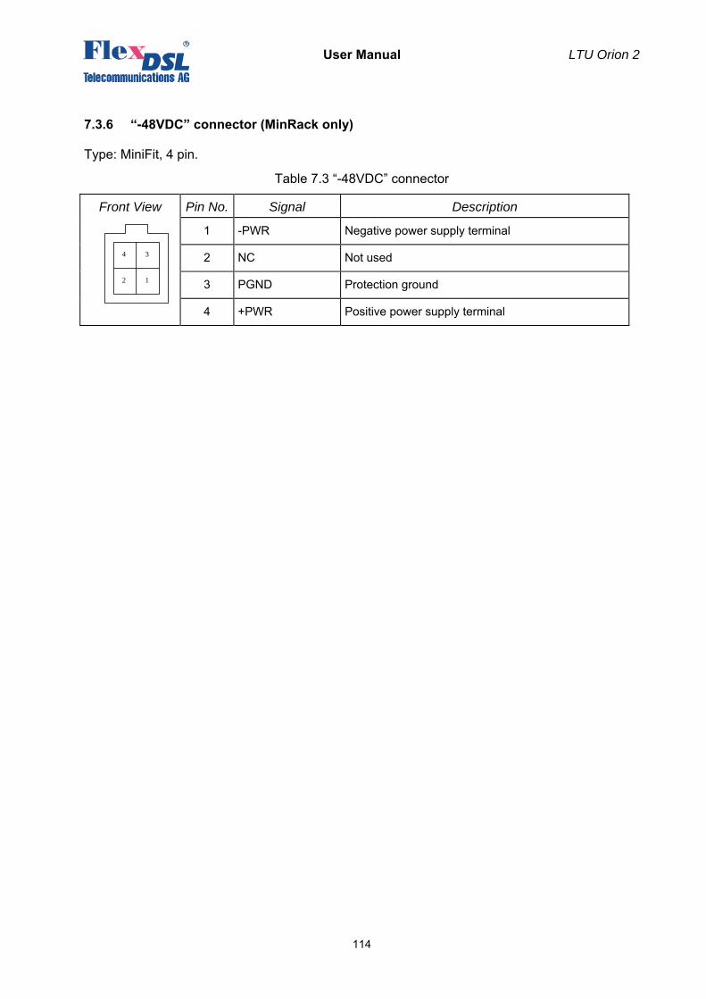
User Manual LTU Orion 2
114
7.3.6 “-48VDС” connector (MinRack only)
Type: MiniFit, 4 pin.
Table 7.3 “-48VDС” connector
Front View Pin No. Signal Description
1 -PWR Negative power supply terminal
2 NC Not used
3 PGND Protection ground
4 +PWR Positive power supply terminal
4 3
2 1
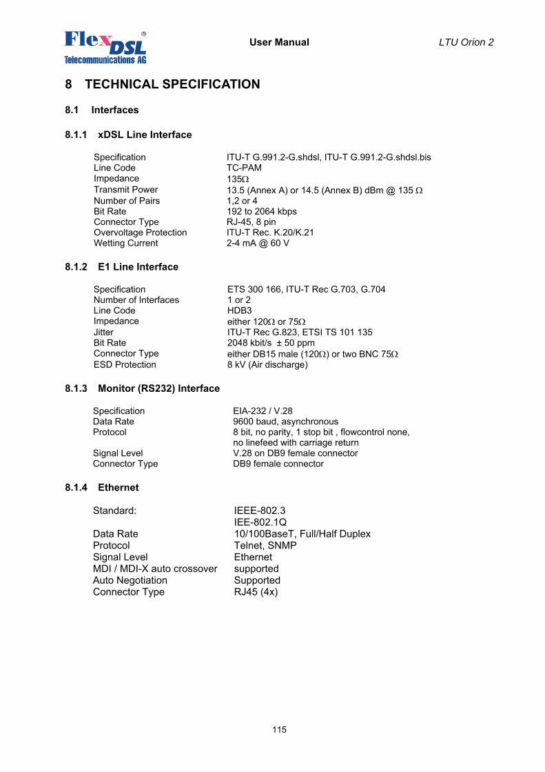
User Manual LTU Orion 2
115
8 TECHNICAL SPECIFICATION
8.1 Interfaces
8.1.1 xDSL Line Interface
Specification ITU-T G.991.2-G.shdsl, ITU-T G.991.2-G.shdsl.bis Line Code TC-PAM Impedance 135Ω Transmit Power 13.5 (Annex A) or 14.5 (Annex B) dBm @ 135 Ω Number of Pairs 1,2 or 4 Bit Rate 192 to 2064 kbps Connector Type RJ-45, 8 pin Overvoltage Protection ITU-T Rec. K.20/K.21 Wetting Current 2-4 mA @ 60 V
8.1.2 E1 Line Interface
Specification ETS 300 166, ITU-T Rec G.703, G.704 Number of Interfaces 1 or 2 Line Code HDB3 Impedance either 120Ω or 75Ω Jitter ITU-T Rec G.823, ETSI TS 101 135 Bit Rate 2048 kbit/s ± 50 ppm Connector Type either DB15 male (120Ω) or two BNC 75Ω ESD Protection 8 kV (Air discharge)
8.1.3 Monitor (RS232) Interface
Specification EIA-232 / V.28 Data Rate 9600 baud, asynchronous Protocol 8 bit, no parity, 1 stop bit , flowcontrol none,
no linefeed with carriage return Signal Level V.28 on DB9 female connector Connector Type DB9 female connector
8.1.4 Ethernet
Standard: IEEE-802.3 IEE-802.1Q
Data Rate 10/100BaseT, Full/Half Duplex Protocol Telnet, SNMP Signal Level Ethernet MDI / MDI-X auto crossover supported Auto Negotiation Supported Connector Type RJ45 (4x)
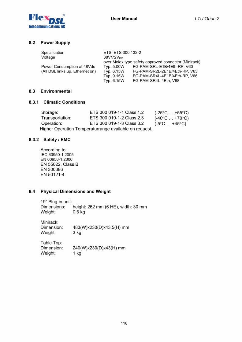
User Manual LTU Orion 2
116
8.2 Power Supply
Specification ETSI ETS 300 132-2 Voltage 38V/72VDC
over Molex type safety approved connector (Minirack) Power Consumption at 48Vdc (All DSL links up, Ethernet on)
Typ. 5.00W FG-PAM-SRL-E1B/4Eth-RP, V60 Typ. 6.15W FG-PAM-SR2L-2E1B/4Eth-RP, V63 Typ. 9.15W FG-PAM-SR4L-4E1B/4Eth-RP, V66 Typ. 6.15W FG-PAM-SR4L-4Eth, V68
8.3 Environmental
8.3.1 Climatic Conditions
Storage: ETS 300 019-1-1 Class 1.2 (-25°C … +55°C) Transportation: ETS 300 019-1-2 Class 2.3 (-40°C … +70°C) Operation: ETS 300 019-1-3 Class 3.2 (-5°C … +45°C)
Higher Operation Temperaturrange available on request.
8.3.2 Safety / EMC
According to: IEC 60950-1:2005 EN 60950-1:2006 EN 55022, Class B EN 300386 EN 50121-4
8.4 Physical Dimensions and Weight
19“ Plug-in unit: Dimensions: height: 262 mm (6 HE), width: 30 mm Weight: 0.6 kg
Minirack: Dimension: 483(W)x230(D)x43.5(H) mm Weight: 3 kg
Table Top: Dimension: 240(W)x230(D)x43(H) mm Weight: 1 kg