Embed Size (px)
Citation preview
Hegel 1 30th Annual AIAA/USU
Conference on Small Satellites
SSC16-X-7
FlexCore: Low-Cost Attitude Determination and Control Enabling High-Performance
Small Spacecraft
Daniel Hegel
Blue Canyon Technologies
2425 55th St. Suite A-200, Boulder, CO, 80301; 720 458-0703
ABSTRACT
One of the most important, yet complex, and expensive subsystems for virtually any spacecraft mission is the
attitude determination and control subsystem (ADCS). Many payloads require precision ADCS to achieve the
desired performance; however, such precision is typically cost-prohibitive for small spacecraft. To address this
problem, Blue Canyon Technologies (BCT) has developed FlexCore, which is a highly-configurable ADCS that
uses a core electronics box (based on the XACT cubesat ADCS), combined with any of the various reaction wheel
sizes in the BCT product line. The FlexCore electronics and software stays the same, regardless of the spacecraft.
The wide range of reaction wheel and torque rod sizes supports spacecraft sizes from large CubeSats to 100s of
kilograms. The stellar-based attitude determination and control provides accuracy of 0.002-deg, RMS. Features of
FlexCore include: multiple nano star trackers with integrated stray-light baffles; 3 or 4 low-jitter reaction wheels; 3
torque rods; GPS receiver; MEMS IMU; MEMS magnetometer; sun sensors; integrated processor and electronics;
auto-generated flight software, including star identification, Kalman filter, momentum control, thruster control, and
orbit propagation. The table-driven, auto-coded software is easily configured to support any mission, and is
delivered to the user fully programmed.
INTRODUCTION
As the growth of the smallsat market continues, so does
the desire for less expensive spacecraft. One of the
most important, yet complex, and expensive subsystems
for virtually any spacecraft mission is the attitude
determination and control subsystem (ADCS). Many
payloads require precision ADCS to achieve the desired
performance; however, such precision is typically cost-
prohibitive for small spacecraft. Leveraging much from
their successful XACT cubesat ADCS, BCT has
developed a very cost-effective, high-performance
ADCS that can support ESPA-class spacecraft, and
beyond.
CUBESAT POINTING SOLUTION
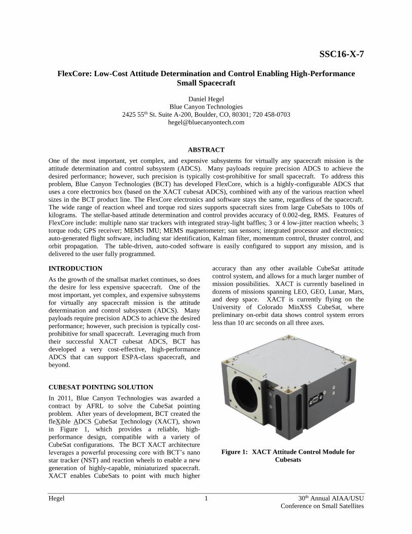
In 2011, Blue Canyon Technologies was awarded a
contract by AFRL to solve the CubeSat pointing
problem. After years of development, BCT created the
fleXible ADCS CubeSat Technology (XACT), shown
in Figure 1, which provides a reliable, high-
performance design, compatible with a variety of
CubeSat configurations. The BCT XACT architecture
leverages a powerful processing core with BCT’s nano
star tracker (NST) and reaction wheels to enable a new
generation of highly-capable, miniaturized spacecraft.
XACT enables CubeSats to point with much higher
accuracy than any other available CubeSat attitude
control system, and allows for a much larger number of
mission possibilities. XACT is currently baselined in
dozens of missions spanning LEO, GEO, Lunar, Mars,
and deep space. XACT is currently flying on the
University of Colorado MinXSS CubeSat, where
preliminary on-orbit data shows control system errors
less than 10 arc seconds on all three axes.
Figure 1: XACT Attitude Control Module for
Cubesats

Hegel 2 30th Annual AIAA/USU
Conference on Small Satellites
Features of XACT include:
Nano Star Tracker for precise attitude deter-
mination (w/ integrated stray light baffle)
Three micro-sized reaction wheels enabling
precise 3-axis control
Three torque rods
MEMS IMU
MEMS Magnetometer
Sun sensors
Hyper-integrated electronics board
Integrated Electronics
One of the many innovations with XACT is the
collection of all electronics into a single highly-
integrated processor board. Key features of the
processor board are:
• FPGA with LEON soft-core processor
• SDRAM, DPRAM, FLASH memory
• Sensor/Actuator interfaces
– Reaction wheel and torque rod
drivers
– A2D converters
– SPI and I2C
– GPSR data interface, and micro-
second 1PPS timing
• Latching relay for image boot selection
• Volt regulators/converters
SMALL-SAT POINTING SOLUTION
Whereas the XACT avionics were primarily designed
for CubeSats, their functionality is expandable to much
larger spacecraft by simply utilizing one of BCT’s
larger reaction wheel and torque rod sizes.
The first variation is XACT-Core, in which the internal
micro wheels and torque rods are replaced with three or
four larger external wheels and rods from BCT’s line of
products. The first program to utilize this is the
DARPA SeeMe spacecraft developed by Raytheon,
shown in Figure 2. This system is typically utilized in
spacecraft less than 50kg.
The second variation, and most capable, is FlexCore, in
which multiple external NSTs (detached from the
electronics core) are used, along with three or four
wheels having momentum as high as 1.5 Nms (with
larger currently in development). The external trackers
can be placed as needed around the spacecraft for
optimal pointing performance, and provide higher-
precision pointing and redundancy. This system is
baselined in multiple Air Force ESPA-class missions.
Figure 3 shows an example of FlexCore flight
hardware.
Figure 2: XACT-Core ADCS Hardware
Figure 3: FlexCore ADCS Hardware
Figure 4 contains a series of block diagrams that
illustrate the similarities and differences of the XACT,
XACT-Core, and FlexCore products.

Hegel 3 30th Annual AIAA/USU
Conference on Small Satellites
Figure 4: Summary of XACT and FlexCore
Configurations
For each of the systems, the flight software supports
closed-loop simulation during system integration and
test, providing a test-like-you-fly environment.
Interfaces to an optional propulsion subsystem are
accommodated and propulsion software has been
implemented.
Nano Star Tracker
The key component for achieving precision attitude
determination is the nano star tracker, shown in Figure
5.
Figure 5: Nano Star Tracker (NST)
Features of the star tracker include:
• Star-light in –> attitude quaternion out, at 5Hz
• Lost-in-space initial attitude solution within 4
seconds.
• Tracks stars down to 7.5 magnitude
• Can process up to 64 stars at once
• On-board star catalog >23,000 entries
• Integrated high-performance stray-light baffle
• Supports photo/video mode with full image or
region of interest (ROI)
One of the most important (and most difficult) steps in
star tracker operation is determining which stars the
tracker is looking at. Without that, it has no way of
knowing how it is oriented in space. The NST star ID
algorithm is robust and efficient, and employs the
following features:
• Efficient database structure and search
algorithm to achieve Lost-in-Space star ID in
<4 seconds
• Completely insensitive to absolute star
magnitude knowledge
• Very insensitive to relative star magnitude
knowledge
• Simulations with high relative magnitude
errors, high centroid errors, and an unknown
bright object in the FOV show >99.5% success
rate
• Has demonstrated successful star ID with
detector 80% saturated with ambient stray
light
Hegel 4 30th Annual AIAA/USU
Conference on Small Satellites
The NST can perform star ID at rotation rates of at least
1 deg/s.
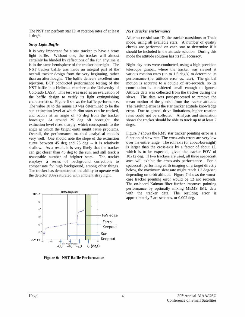
Stray Light Baffle
It is very important for a star tracker to have a stray
light baffle. Without one, the tracker will almost
certainly be blinded by reflections of the sun anytime it
is in the same hemisphere of the tracker boresight. The
NST tracker baffle was made an integral part of the
overall tracker design from the very beginning, rather
than an afterthought. The baffle delivers excellent sun
rejection. BCT conducted performance testing of the
NST baffle in a Heliostat chamber at the University of
Colorado LASP. This test was used as an evaluation of
the baffle design to verify its light extinguishing
characteristics. Figure 6 shows the baffle performance.
The value 10 to the minus 10 was determined to be the
sun extinction level at which dim stars can be tracked,
and occurs at an angle of 45 deg from the tracker
boresight. At around 25 deg off boresight, the
extinction level rises sharply, which corresponds to the
angle at which the bright earth might cause problems.
Overall, the performance matched analytical models
very well. One should note the slope of the extinction
curve between 45 deg and 25 deg -- it is relatively
shallow. As a result, it is very likely that the tracker
can get closer than 45 deg to the sun, and still track a
reasonable number of brighter stars. The tracker
employs a series of background corrections to
compensate for high background, among other things.
The tracker has demonstrated the ability to operate with
the detector 80% saturated with ambient stray light.
Figure 6: NST Baffle Performance
NST Tracker Performance
After successful star ID, the tracker transitions to Track
mode, using all available stars. A number of quality
checks are performed on each star to determine if it
should be included in the attitude solution. During this
mode the attitude solution has its full accuracy.
Night sky tests were conducted, using a high-precision
telescope gimbal, where the tracker was slewed at
various rotation rates (up to 1.5 deg/s) to determine its
performance (i.e. attitude error vs. rate). The gimbal
motion is accurate to a couple of arc-seconds, so its
contribution is considered small enough to ignore.
Attitude data was collected from the tracker during the
slews. The data was post-processed to remove the
mean motion of the gimbal from the tracker attitude.
The resulting error is the star tracker attitude knowledge
error. Due to gimbal drive limitations, higher rotation
rates could not be collected. Analysis and simulation
shows the tracker should be able to track up to at least 2
deg/s.
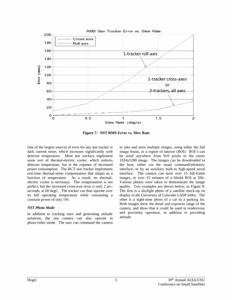
Figure 7 shows the RMS star tracker pointing error as a
function of slew rate. The cross-axis errors are very low
over the entire range. The roll axis (or about-boresight)
is larger than the cross-axis by a factor of about 12,
which is to be expected, given the tracker FOV of
10x12 deg. If two trackers are used, all three spacecraft
axes will exhibit the cross-axis performance. For a
spacecraft performing earth imaging of a target directly
below, the maximum slew rate might reach 1.3 deg/sec,
depending on orbit altitude. Figure 7 shows the worst-
case tracker pointing error would be 12 arc seconds.
The on-board Kalman filter further improves pointing
performance by optimally mixing MEMS IMU data
with the tracker data. The resulting error is
approximately 7 arc seconds, or 0.002 deg.
Hegel 5 30th Annual AIAA/USU
Conference on Small Satellites
Figure 7: NST RMS Error vs. Slew Rate
One of the largest sources of error for any star tracker is
dark current noise, which increases significantly with
detector temperature. Most star trackers implement
some sort of thermal-electric cooler, which reduces
detector temperature, but at the expense of increased
power consumption. The BCT star tracker implements
real-time thermal-noise compensation that adapts as a
function of temperature. As a result, no thermal-
electric cooler is necessary. The compensation is not
perfect, but the increased cross-axis error is only 2 arc-
seconds, at 60 degC. The tracker can thus operate over
its full operating temperature while consuming a
constant power of only 1W.
NST Photo Mode
In addition to tracking stars and generating attitude
solutions, the star camera can also operate in
photo/video mode. The user can command the camera
to take and store multiple images, using either the full
image frame, or a region of interest (ROI). ROI’s can
be sized anywhere from 9x9 pixels to the entire
1024x1280 image. The images can be downloaded to
the host, either via the usual command/telemetry
interface, or by an auxiliary built-in high-speed serial
interface. The camera can store over 15 full-frame
images, or over 15 minutes of a 64x64 ROI at 5Hz.
Various photos were taken to demonstrate the image
quality. Two examples are shown below, in Figure 8.
The first is a daylight photo of a satellite mock-up on
display in the University of Colorado LASP lobby. The
other is a night-time photo of a car in a parking lot.
Both images show the detail and exposure range of the
camera, and show that it could be used in rendezvous
and proximity operation, in addition to providing
attitude.

Hegel 6 30th Annual AIAA/USU
Conference on Small Satellites
Figure 8: NST Photo Mode Images
Reaction Wheel Design
The BCT family of reaction wheels are designed for
long life and low jitter. BCT designs the motors in-
house to achieve the desired torque/speed
characteristics, and to guarantee the desired quality and
reliability. Figure 9 shows the BCT family of reaction
wheels that can support CubeSats to ESPA-class and
larger. The RWp015 wheels are used in internally with
XACT. The RWp050 through RWp500 can be used
with XACT-Core, and RWp500 and RW1 are typically
used with FlexCore.
Figure 9: BCT Reaction Wheels
Hegel 7 30th Annual AIAA/USU
Conference on Small Satellites
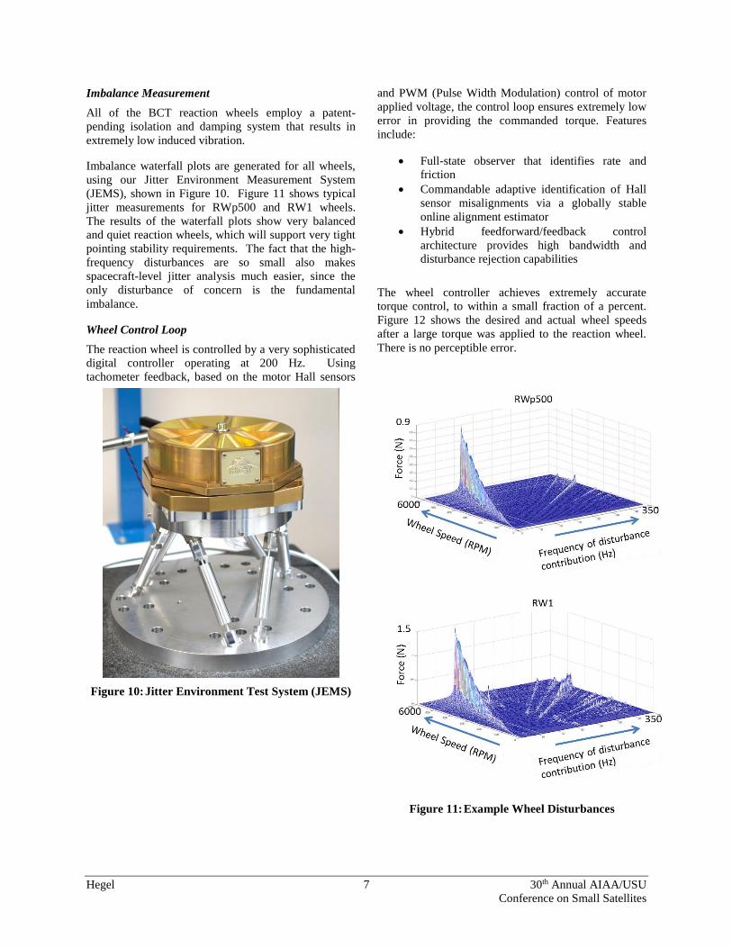
Imbalance Measurement
All of the BCT reaction wheels employ a patent-
pending isolation and damping system that results in
extremely low induced vibration.
Imbalance waterfall plots are generated for all wheels,
using our Jitter Environment Measurement System
(JEMS), shown in Figure 10. Figure 11 shows typical
jitter measurements for RWp500 and RW1 wheels.
The results of the waterfall plots show very balanced
and quiet reaction wheels, which will support very tight
pointing stability requirements. The fact that the high-
frequency disturbances are so small also makes
spacecraft-level jitter analysis much easier, since the
only disturbance of concern is the fundamental
imbalance.
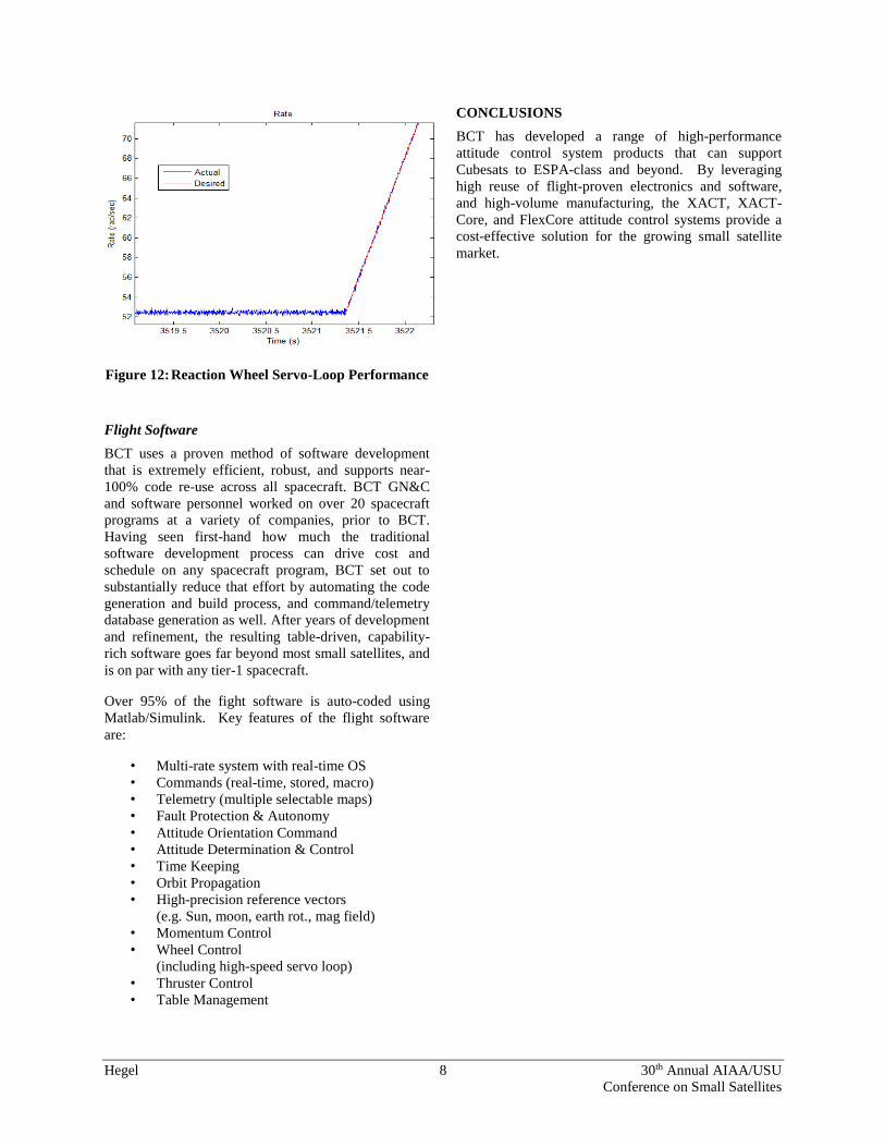
Wheel Control Loop
The reaction wheel is controlled by a very sophisticated
digital controller operating at 200 Hz. Using
tachometer feedback, based on the motor Hall sensors
and PWM (Pulse Width Modulation) control of motor
applied voltage, the control loop ensures extremely low
error in providing the commanded torque. Features
include:
Full-state observer that identifies rate and
friction
Commandable adaptive identification of Hall
sensor misalignments via a globally stable
online alignment estimator
Hybrid feedforward/feedback control
architecture provides high bandwidth and
disturbance rejection capabilities
The wheel controller achieves extremely accurate
torque control, to within a small fraction of a percent.
Figure 12 shows the desired and actual wheel speeds
after a large torque was applied to the reaction wheel.
There is no perceptible error.
Figure 10: Jitter Environment Test System (JEMS)
Figure 11: Example Wheel Disturbances
Hegel 8 30th Annual AIAA/USU
Conference on Small Satellites
Figure 12: Reaction Wheel Servo-Loop Performance
Flight Software
BCT uses a proven method of software development
that is extremely efficient, robust, and supports near-
100% code re-use across all spacecraft. BCT GN&C
and software personnel worked on over 20 spacecraft
programs at a variety of companies, prior to BCT.
Having seen first-hand how much the traditional
software development process can drive cost and
schedule on any spacecraft program, BCT set out to
substantially reduce that effort by automating the code
generation and build process, and command/telemetry
database generation as well. After years of development
and refinement, the resulting table-driven, capability-
rich software goes far beyond most small satellites, and
is on par with any tier-1 spacecraft.
Over 95% of the fight software is auto-coded using
Matlab/Simulink. Key features of the flight software
are:
• Multi-rate system with real-time OS
• Commands (real-time, stored, macro)
• Telemetry (multiple selectable maps)
• Fault Protection & Autonomy
• Attitude Orientation Command
• Attitude Determination & Control
• Time Keeping
• Orbit Propagation
• High-precision reference vectors
(e.g. Sun, moon, earth rot., mag field)
• Momentum Control
• Wheel Control
(including high-speed servo loop)
• Thruster Control
• Table Management
CONCLUSIONS
BCT has developed a range of high-performance
attitude control system products that can support
Cubesats to ESPA-class and beyond. By leveraging
high reuse of flight-proven electronics and software,
and high-volume manufacturing, the XACT, XACT-
Core, and FlexCore attitude control systems provide a
cost-effective solution for the growing small satellite
market.