Embed Size (px)
Citation preview

November 3, 2003 F.M. Doyle, D.A. Dornfeld, J.B. Talbot
1
FLCC
Feature Level Compensation and Control: Chemical Mechanical
Planarization
Investigators
Fiona M. Doyle, Dept. of Materials Science and Engineering
David A. Dornfeld, Dept. of Mechanical Engineering
University of California, Berkeley
Jan B. Talbot, Dept. of Chemical Engineering, University of California, San Diego

November 3, 2003 F.M. Doyle, D.A. Dornfeld, J.B. Talbot
2
FLCC
Students Involved in CMP EffortMechanical Aspects
Andrew Chang (RAPT Technologies)
Yongsik Moon (Applied Materials)
Jianfeng Luo(Cypress Semiconductor)
Inkil Edward Hwang Sunghoon Lee Jihong Choi
Chemical Aspects Serdar Aksu (Suleyman
Demiril University, Isparta, Turkey)
Ling Wang
Interfacial and Colloid Aspects
Tanuja Gopal (UCSD)

November 3, 2003 F.M. Doyle, D.A. Dornfeld, J.B. Talbot
3
FLCC
Outline
Objective of FLCC effort in CMP Background on CMP Mechanical phenomena Interfacial and colloidal phenomena Chemical phenomena Modeling efforts Future work

November 3, 2003 F.M. Doyle, D.A. Dornfeld, J.B. Talbot
4
FLCC
Objective of FLCC effort in CMP
November 3, 2003 F.M. Doyle, D.A. Dornfeld, J.B. Talbot
5
FLCC
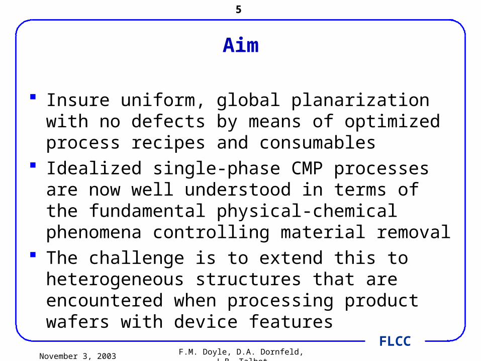
Aim
Insure uniform, global planarization with no defects by means of optimized process recipes and consumables
Idealized single-phase CMP processes are now well understood in terms of the fundamental physical-chemical phenomena controlling material removal
The challenge is to extend this to heterogeneous structures that are encountered when processing product wafers with device features
November 3, 2003 F.M. Doyle, D.A. Dornfeld, J.B. Talbot
6
FLCC
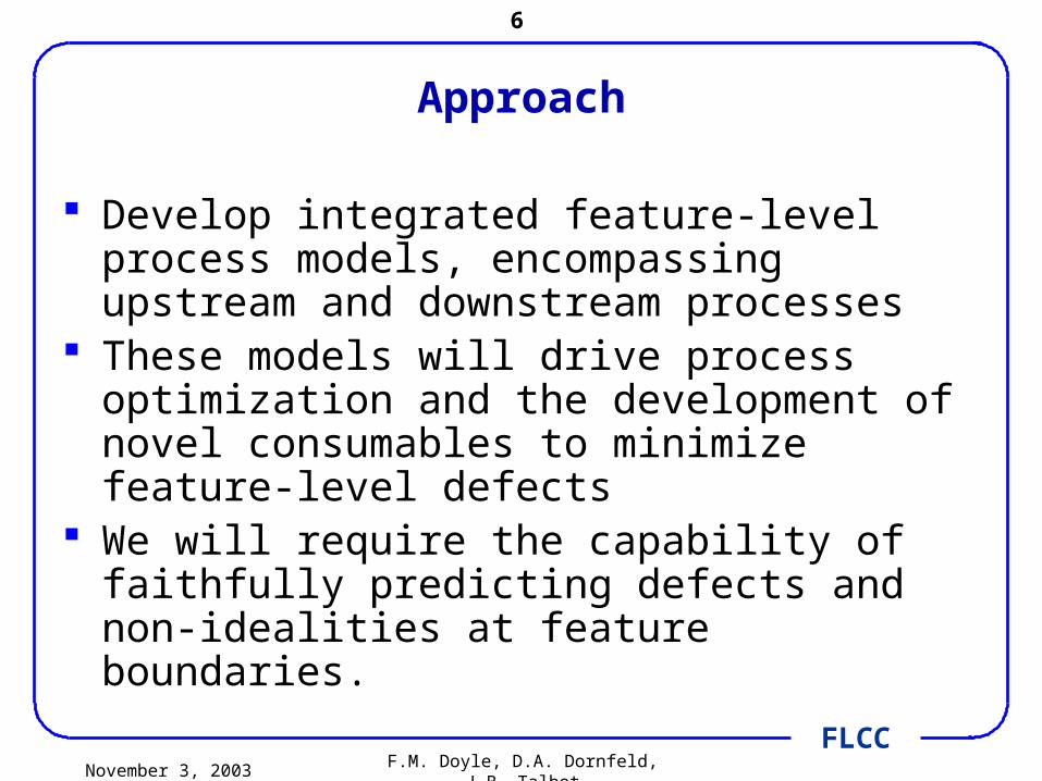
Approach
Develop integrated feature-level process models, encompassing upstream and downstream processes
These models will drive process optimization and the development of novel consumables to minimize feature-level defects
We will require the capability of faithfully predicting defects and non-idealities at feature boundaries.

November 3, 2003 F.M. Doyle, D.A. Dornfeld, J.B. Talbot
7
FLCC
Background on CMP
November 3, 2003 F.M. Doyle, D.A. Dornfeld, J.B. Talbot
8
FLCC
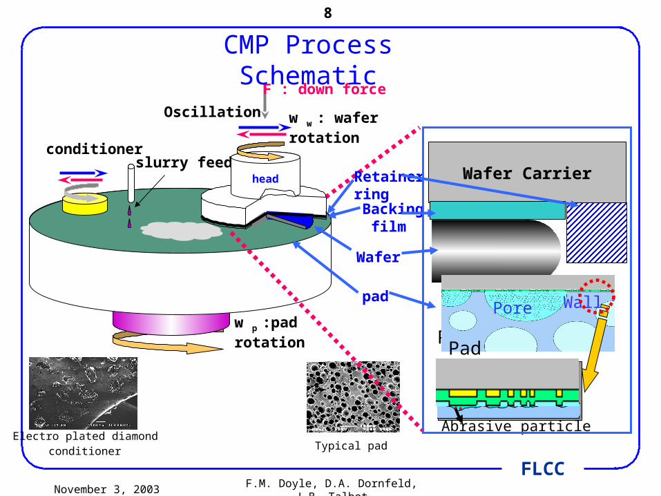
w p :pad rotation
tablepad
slurry feedconditioner
head
w w : wafer rotationOscillation
F : down force
Backing film
Retainerring
Wafer
Wafer Carrier
Pad
Pore Wall
Abrasive particle
CMP Process Schematic
Electro plated diamond conditioner Typical pad
Wall
Pad
Pore
November 3, 2003 F.M. Doyle, D.A. Dornfeld, J.B. Talbot
9
FLCC
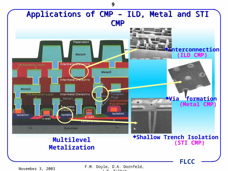
Via formation (Metal CMP)
Shallow Trench Isolation (STI CMP)Multilevel Metalization
Interconnection(ILD CMP)
Applications of CMP – ILD, Metal and STI CMPApplications of CMP – ILD, Metal and STI CMP

November 3, 2003 F.M. Doyle, D.A. Dornfeld, J.B. Talbot
10
FLCC
Idealized CMP
Silicon wafer
Polishing pad
Abrasive particle
‘Softened’ surface by chemical reaction
Pad asperity
November 3, 2003 F.M. Doyle, D.A. Dornfeld, J.B. Talbot
11
FLCC
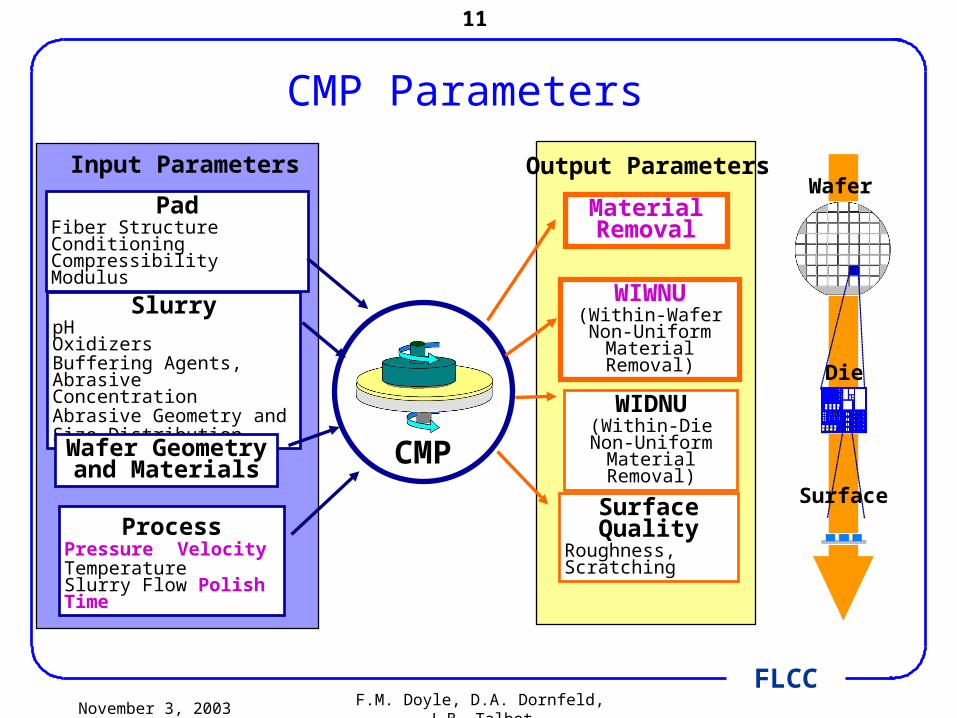
CMP Parameters
PadFiber Structure Conditioning Compressibility Modulus
SlurrypH OxidizersBuffering Agents, Abrasive ConcentrationAbrasive Geometry andSize Distribution
Wafer Geometry and
Materials
ProcessPressure VelocityTemperatureSlurry Flow Polish Time
WIWNU(Within-Wafer Non-Uniform
Material Removal)
WIDNU(Within-Die Non-
Uniform Material Removal)
Material Removal
Surface Quality
Roughness, Scratching
CMP
Input Parameters Output ParametersWafer
Die
Surface

November 3, 2003 F.M. Doyle, D.A. Dornfeld, J.B. Talbot
12
FLCC
Interactions between Input Variables
Polishing pad
Abrasive particles in Fluid (All inactive)
Pad asperity
Active abrasives on Contact area
Vol Chemically Influenced Wafer Surface
Wafer
Abrasive particles on Contact area with number N
Source: J. Luo and D. Dornfeld, IEEE Trans: Semiconductor Manufacturing, 2001
Velocity V
Interactions Wafer Pad Abrasive Slurry chemical
Wafer - √ √ √
Pad √ - √ √
Abrasive √ √ - √
Slurry chemical
√ √ √ -
Recognize that wafer is heterogeneous, and there may not be a single interaction between it
and other input variables

November 3, 2003 F.M. Doyle, D.A. Dornfeld, J.B. Talbot
13
FLCC
Chemical Mechanical Planarization
Mechanical Phenomena
Chemical Phenomena
Interfacial and Colloid
Phenomena
November 3, 2003 F.M. Doyle, D.A. Dornfeld, J.B. Talbot
14
FLCC
Mechanical Phenomena

November 3, 2003 F.M. Doyle, D.A. Dornfeld, J.B. Talbot
15
FLCC
Gap effects on “mechanics”
Pad-based removal
Slurry-based removal
‘Small’ gap
‘Big’ gap
Silicon wafer
Polishing pad
Abrasive particle
Delaminated by brushing
Eroded surface by chemical reaction--- softening
Silicon wafer
Polishing pad
Abrasive particles

November 3, 2003 F.M. Doyle, D.A. Dornfeld, J.B. Talbot
16
FLCC
Stribeck Curve and Characteristics of slurry film thickness
Fric
t ion
coe
f fic
ien t
Film
thi
ckne
ss
Pressure
VelocityViscosity ⋅Hershey number(= )
Hydrodynamic
lubrication
Elasto-
hydrodynamic
lubrication
Boundary
lubrication
Direct
contact
Semi-direct
contact
Hydroplane
sliding
Stribeck curve
Polishing pad
Wafer Slurry
Direct contact
Semi-direct contact
Hydroplane sliding
November 3, 2003 F.M. Doyle, D.A. Dornfeld, J.B. Talbot
17
FLCC
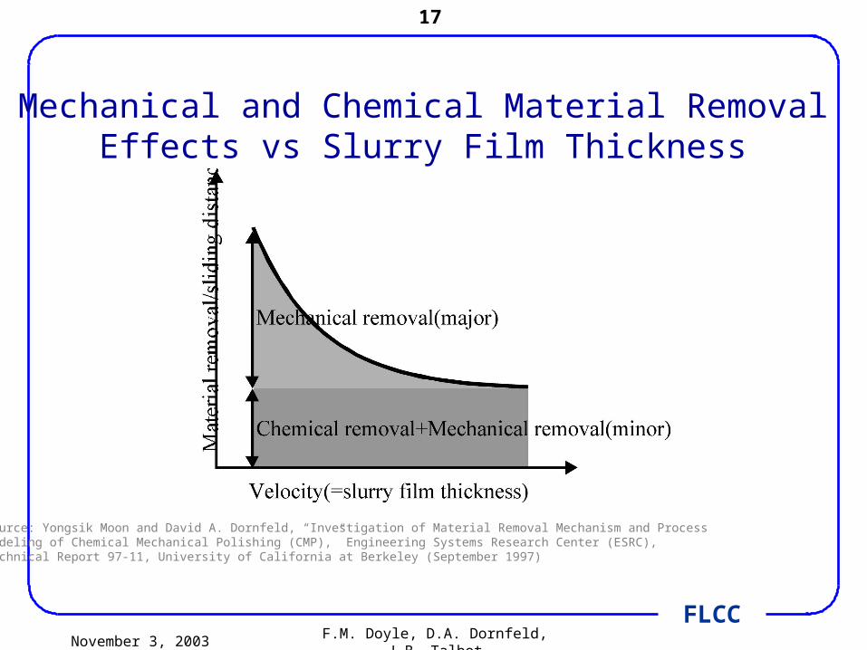
Mechanical and Chemical Material RemovalEffects vs Slurry Film Thickness
Source: Yongsik Moon and David A. Dornfeld, “Investigation of Material Removal Mechanism and ProcessModeling of Chemical Mechanical Polishing (CMP),” Engineering Systems Research Center (ESRC),Technical Report 97-11, University of California at Berkeley (September 1997)
November 3, 2003 F.M. Doyle, D.A. Dornfeld, J.B. Talbot
18
FLCC
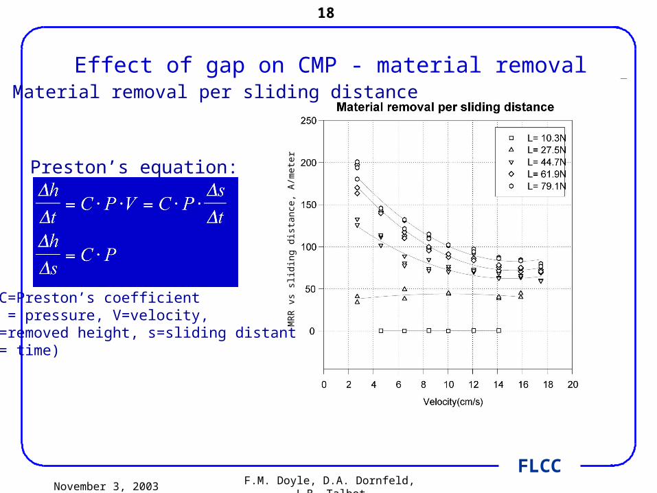
Effect of gap on CMP - material removal
Preston’s equation:
(C=Preston’s coefficientP = pressure, V=velocity,h=removed height, s=sliding distantt= time)
• Material removal per sliding distance
MR
R v
s sl
idin
g d
ista
nce
, A
/mete
r
November 3, 2003 F.M. Doyle, D.A. Dornfeld, J.B. Talbot
19
FLCC
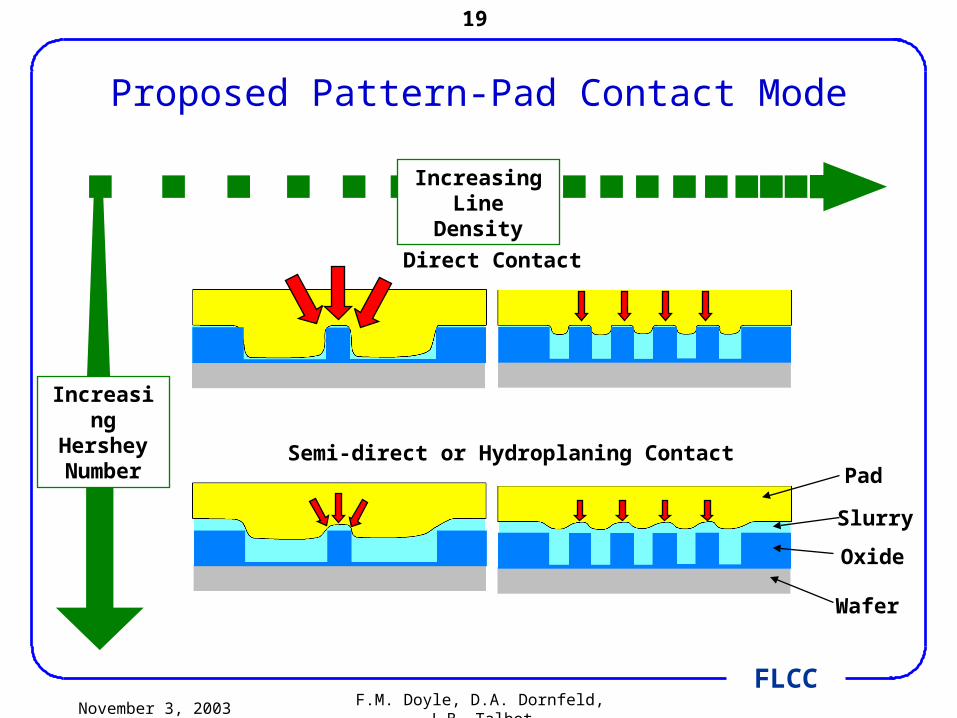
Proposed Pattern-Pad Contact Mode
Oxide
Pad
Slurry
Wafer
Semi-direct or Hydroplaning Contact
Direct Contact
Increasing Hershey Number
Increasing Line Density
November 3, 2003 F.M. Doyle, D.A. Dornfeld, J.B. Talbot
20
FLCC
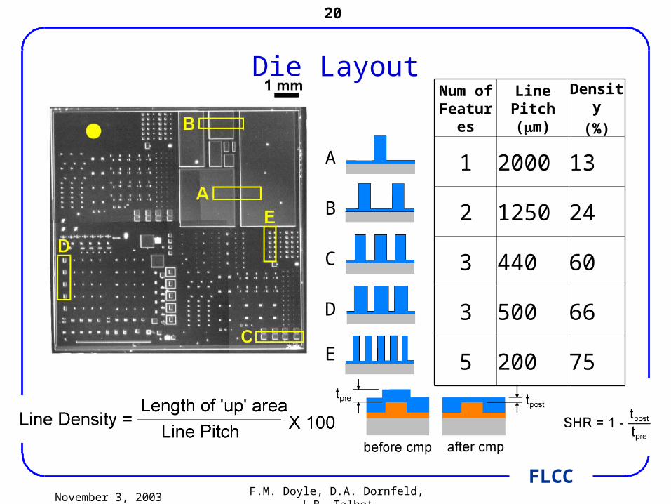
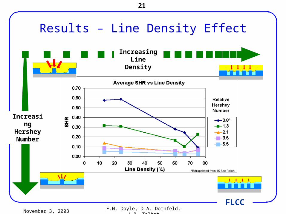
Die LayoutNum of
FeaturesLine Pitch
(m)Density
(%)
1 2000 13
2 1250 24
3 440 60
3 500 66
5 200 75
A
B
C
D
E
November 3, 2003 F.M. Doyle, D.A. Dornfeld, J.B. Talbot
21
FLCC
Results – Line Density Effect
Increasing Hershey Number
Increasing Line Density
November 3, 2003 F.M. Doyle, D.A. Dornfeld, J.B. Talbot
22
FLCC
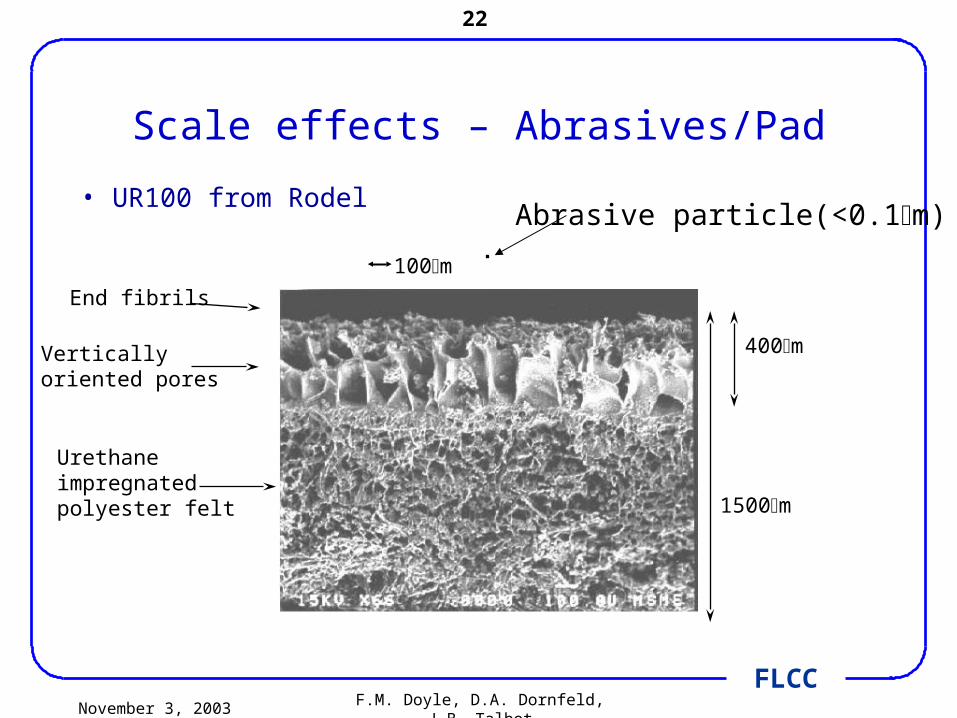
Scale effects – Abrasives/Pad
• UR100 from Rodel
1500m
100m
400m
End fibrils
Vertically oriented pores
Urethane impregnated polyester felt
Abrasive particle(<0.1m)
November 3, 2003 F.M. Doyle, D.A. Dornfeld, J.B. Talbot
23
FLCC
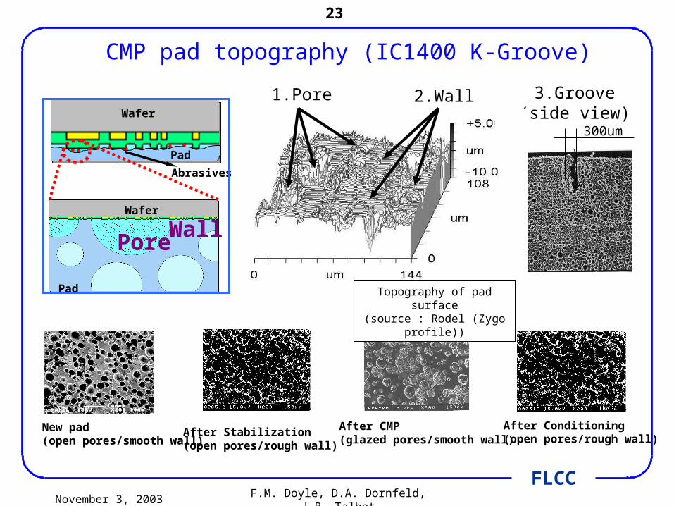
CMP pad topography (IC1400 K-Groove)
New pad(open pores/smooth wall)
After Stabilization(open pores/rough wall)
After CMP(glazed pores/smooth wall)
After Conditioning(open pores/rough wall)
300um
3.Groove(side view)
Topography of pad surface(source : Rodel (Zygo profile))
1.Pore 2.Wall
Pad
Wafer
PoreWall
Abrasives
Wafer
Pad

November 3, 2003 F.M. Doyle, D.A. Dornfeld, J.B. Talbot
24
FLCC
Pad becomes glazed during polishing
Pad Porosity and Surface Roughness are affected
Slurry transport, contact area and by-product removal deteriorate
Conditioning needed to break up glazed areas
The Need for Conditioning
100 µm
Source: B. J. Hooper, UCD, Dublin, 2001
New
Conditioned
Glazed

November 3, 2003 F.M. Doyle, D.A. Dornfeld, J.B. Talbot
25
FLCC
Groove & Pore
Wall
Protrusion for rough wall
200um
Soft Material(i.e. low stiffness)
Top View
Side View
Hard Material(i.e. high stiffness)
50um(space)
Schematic of SMART pad

November 3, 2003 F.M. Doyle, D.A. Dornfeld, J.B. Talbot
26
FLCC
Model Implementation - Pad Design
SMART pad surface
Polymer pad surface
200um
Polyethylene pad surface
Pad
Wafer
PoreWall
Abrasives
Wafer
Pad

November 3, 2003 F.M. Doyle, D.A. Dornfeld, J.B. Talbot
27
FLCC
Interfacial and colloidal phenomena
November 3, 2003 F.M. Doyle, D.A. Dornfeld, J.B. Talbot
28
FLCC
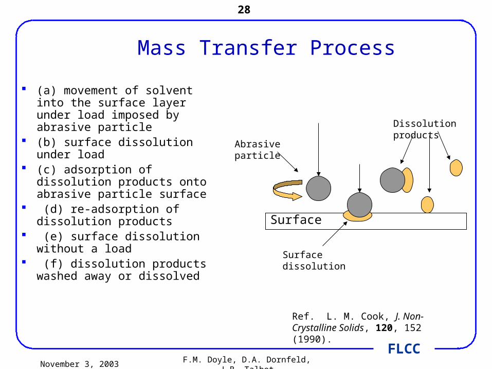
Mass Transfer Process
(a) movement of solvent into the surface layer under load imposed by abrasive particle
(b) surface dissolution under load
(c) adsorption of dissolution products onto abrasive particle surface
(d) re-adsorption of dissolution products
(e) surface dissolution without a load
(f) dissolution products washed away or dissolved
Surface
Dissolution products
Abrasive particle
Surface dissolution
Ref. L. M. Cook, J. Non-Crystalline Solids, 120, 152 (1990).

November 3, 2003 F.M. Doyle, D.A. Dornfeld, J.B. Talbot
29
FLCC
Electrical Double Layer of Abrasive Particles
+ +
++
+
+ + +++
+
++
++
+
+
+
+
+
+
a
+
+
+
Distance
Pote
ntia
l
1/
Diffuse Layer
Shear Plane
Particle Surface
•Potential at surface usually stems from adsorption of lattice ions, H+
or OH-
•Potential is highly sensitive to chemistry of slurry
•Slurries are stable when all particles carry same charge; electrical repulsion overcomes Van de Waals attractive forces
•If potentials are near zero, abrasive particles may agglomerate

November 3, 2003 F.M. Doyle, D.A. Dornfeld, J.B. Talbot
30
FLCC
Colloidal effects
• Maximum polishing rates for glass observed compound IEP ~ solution pH > surface IEP(Cook, 1990)
• Polishing rate dependent upon colloidal particle - W in KIO3 slurries (Stein et al., J. Electrochem. Soc. 1999)
Pol
ish
ing
rate
(
/min
)
Colloid oxide
Gla
ss p
olis
hin
g ra
te (m
/min
)
Oxide Isoelectric point
November 3, 2003 F.M. Doyle, D.A. Dornfeld, J.B. Talbot
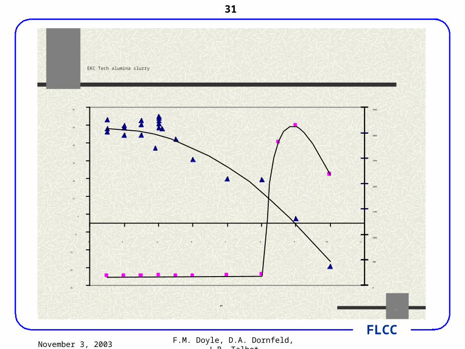
31
FLCC
6
EKC Tech alumina slurry
-35
-25
-15
-5
5
15
25
35
45
55
65
3 4 5 6 7 8 9 10 11
pH
Zeta Potential (mV)
0
500
1000
1500
2000
2500
3000
3500
Effective Particle Size (nm)

November 3, 2003 F.M. Doyle, D.A. Dornfeld, J.B. Talbot
32
FLCC
Chemical phenomena
November 3, 2003 F.M. Doyle, D.A. Dornfeld, J.B. Talbot
33
FLCC
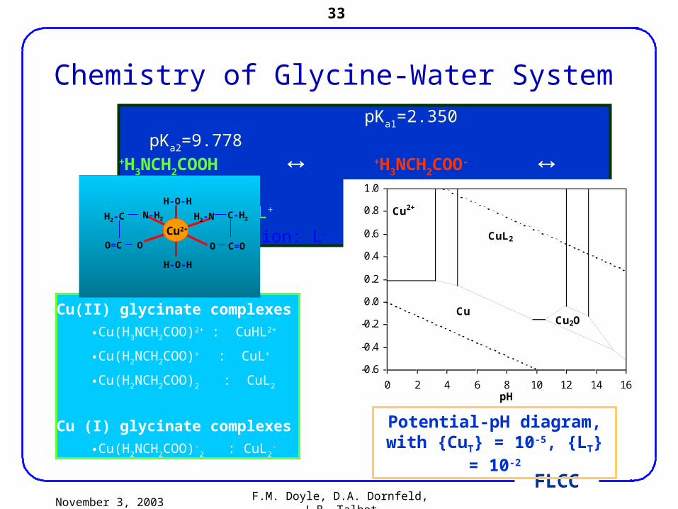
Chemistry of Glycine-Water System pKa1=2.350 pKa2=9.778+H3NCH2COOH +H3NCH2COO- H2NCH2COO-
Cation: H2L+ Zwitterion: HL Anion: L-
-0.6
-0.4
-0.2
0.0
0.2
0.4
0.6
0.8
1.0
0 2 4 6 8 10 12 14 16pH
E, V vs. SHE
Cu2+
CuL2CuL
+
CuO
22-CuO
Cu2OCu
Potential-pH diagram, with {CuT} = 10-5, {LT} = 10-2
Cu(II) glycinate complexes
•Cu(H3NCH2COO)2+ : CuHL2+
•Cu(H2NCH2COO)+ : CuL+
•Cu(H2NCH2COO)2 : CuL2
Cu (I) glycinate complexes
•Cu(H2NCH2COO)-2 : CuL2
-
H-O-H
H-O-H
N-H2H2-C
OO=C
C-H2H2-N
C=OO
Cu2+
November 3, 2003 F.M. Doyle, D.A. Dornfeld, J.B. Talbot
34
FLCC
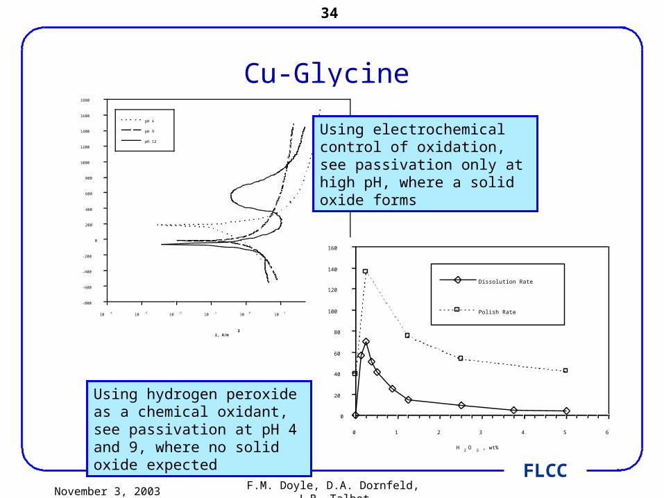
Cu-Glycine
i, A/m2
10-4
10-3
10-2
10-1
100
101
102
103
E mV vs. SHE
-800
-600
-400
-200
0
200
400
600
800
1000
1200
1400
1600
1800
pH 4
pH 9
pH 12
0
20
40
60
80
100
120
140
160
0 1 2 3 4 5 6
H 2 O 2 , wt%
Removal Rate, nm/min
Dissolution Rate
Polish Rate
Using electrochemical control of oxidation, see passivation only at high pH, where a solid oxide forms
Using hydrogen peroxide as a chemical oxidant, see passivation at pH 4 and 9, where no solid oxide expected

November 3, 2003 F.M. Doyle, D.A. Dornfeld, J.B. Talbot
35
FLCC
H2O2 concentration, wt%0 1 2 3 4 5 6concentration of copper ion, mg/L0
20406080100120
Dissolved Copper, nm05001000150020002500
50 minutes40 minutes30 minutes20 minutes10 minutes
Copper concentration, mg/l, and dissolved copper, nm, in unbuffered aqueous glycine (pH 4.5)
sampling time, minutes0 10 20 30 40 50 60
copper ion concentration, mg/L020406080100120
Dissolved Copper, nm050010001500200025000.5 wt% H2O20.75 wt% H2O21 wt% H2O23 wt% H2O25 wt%H2O2

November 3, 2003 F.M. Doyle, D.A. Dornfeld, J.B. Talbot
36
FLCC
Modeling Efforts

November 3, 2003 F.M. Doyle, D.A. Dornfeld, J.B. Talbot
37
FLCC
CMP Modeling Roadmap Objectives from Industrial Viewpoint - VMIC 2001
• Models are not reliable enough to be used as verification of process
• Usefulness of modeling is the ability to give feedback for “what-if” scenarios (predicting “polishability” of new mask designs) in lieu of time-consuming DOE tests
• Models should give some performance prediction for realistic, heterogeneous pattern effects
• Models should predict not only wafer scale phenomena but also have some capability to capture feature/chip scale interaction
November 3, 2003 F.M. Doyle, D.A. Dornfeld, J.B. Talbot
38
FLCC
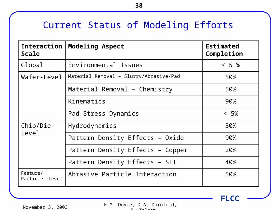
Current Status of Modeling Efforts
Abrasive Particle Interaction
Pattern Density Effects – STI
Pattern Density Effects – Copper
Pattern Density Effects – Oxide
Hydrodynamics
Pad Stress Dynamics
Kinematics
Material Removal – Chemistry
Material Removal – Slurry/Abrasive/Pad
Environmental Issues
Modeling Aspect
Feature/ Particle- Level
Chip/Die-Level
Wafer-Level
Global
Interaction Scale
50%
40%
20%
90%
30%
< 5%
90%
50%
50%
< 5 %
Estimated Completion

November 3, 2003 F.M. Doyle, D.A. Dornfeld, J.B. Talbot
39
FLCC
MRR
Non-uniform
ity
Slurry/W
ater usage
Abrasive
Concentration
Other C
hemical
Effluent
Energy
References
Wafer Level
Feature Level
Die Level
Empirical Model
Preston
Boning
Others
Individual Model
Tribology
Kinematic
Pad
Chemical
Integrated Model
Preston, 1927
Boning, et al, 1997-1998 (4)
Various (10) incl. Burke, Runnels, Zhao
Various (11)
Various (2)
Various (4)
Various (6)
Literature Review of Modeling of CMP

November 3, 2003 F.M. Doyle, D.A. Dornfeld, J.B. Talbot
40
FLCC
Motivations for a Comprehensive Material Removal Model
• Identify the most important input parameters related to Slurry Abrasives, Wafer, and Polishing Pad except the down pressure P0 and velocity V
• Investigate the interactions between the input parameters
• Develop material removal rate formulation to consider the roles of the input parameters and their interactions
• Model as a basis for process design and optimization (including environmental impacts)

November 3, 2003 F.M. Doyle, D.A. Dornfeld, J.B. Talbot
41
FLCC
Past 2-D Material Removal Rate (MRR) Models
•Experimental Model [1]: Preston’s Equation MRR= KeP0V + MRR0 where Ke an all-purpose coefficient, MRR0 a fitting parameter, P0, down pressure, and V, the relative Velocity.
•Analytical Model Considering Wafer-Pad Contact Area[2]: Zhao’s Equation
V
MRR= Ke(P0-Pth)2/3V, where Pth a fitting parameter.
Active abrasive number is proportional to contact area. Contact area P0
2/3
*All with an all purpose factor Ke to represent the roles and interactions of other input variables except the down pressure and velocity
1Preston, 1917, J. of Glass Soc. 2. Zhao et. al., 1999, Applied Physics
Contact Area A
V
P0
P0
Wafer
Pad
Wafer
November 3, 2003 F.M. Doyle, D.A. Dornfeld, J.B. Talbot
42
FLCC
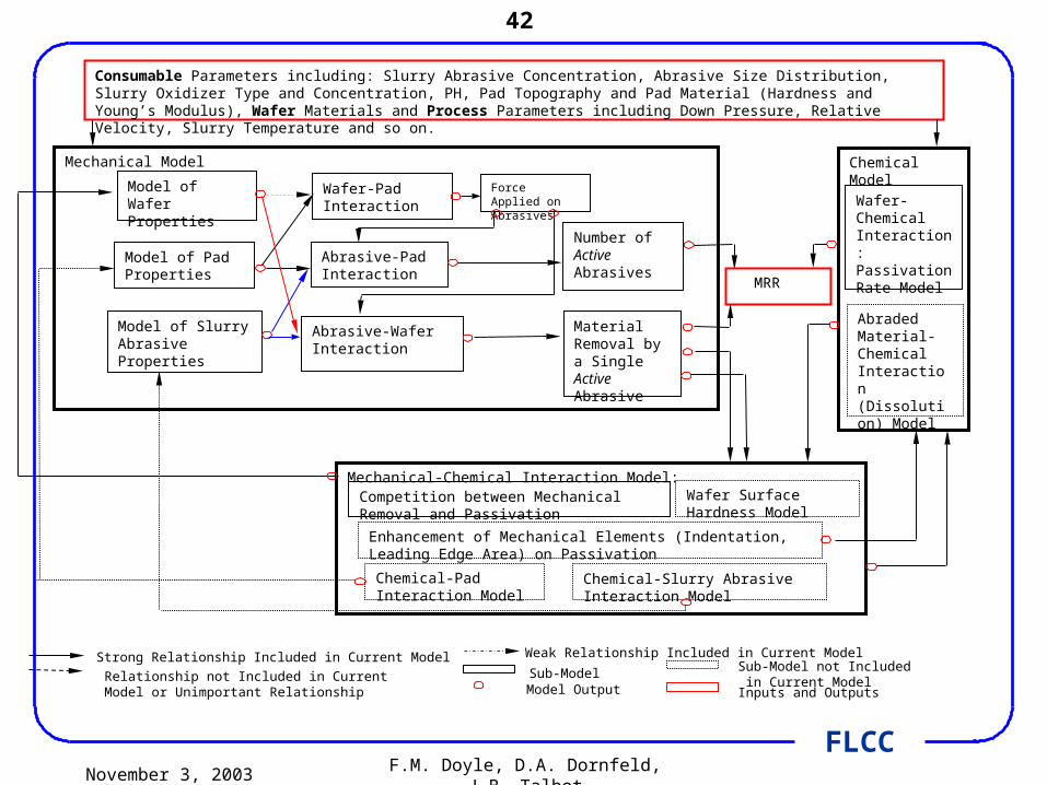
Sub-Model not Included in Current Model
Mechanical Model
Wafer-Pad Interaction
Abrasive-Pad Interaction
Abrasive-Wafer Interaction
Model of Wafer Properties
Model of Pad Properties
Model of Slurry Abrasive Properties
Force Applied on Abrasives
Number of Active Abrasives
Material Removal by a Single Active Abrasive
Chemical Model
Mechanical-Chemical Interaction Model:
Relationship not Included in Current Model or Unimportant Relationship
Strong Relationship Included in Current Model Weak Relationship Included in Current Model
Sub-ModelModel Output
MRR
Consumable Parameters including: Slurry Abrasive Concentration, Abrasive Size Distribution, Slurry Oxidizer Type and Concentration, PH, Pad Topography and Pad Material (Hardness and Young’s Modulus), Wafer Materials and Process Parameters including Down Pressure, Relative Velocity, Slurry Temperature and so on.
Wafer-Chemical Interaction: Passivation Rate Model
Abraded Material-Chemical Interaction (Dissolution) Model
Inputs and Outputs
Wafer Surface Hardness Model
Chemical-Pad Interaction Model
Chemical-Slurry Abrasive Interaction Model
Enhancement of Mechanical Elements (Indentation, Leading Edge Area) on Passivation
Competition between Mechanical Removal and Passivation
November 3, 2003 F.M. Doyle, D.A. Dornfeld, J.B. Talbot
43
FLCC
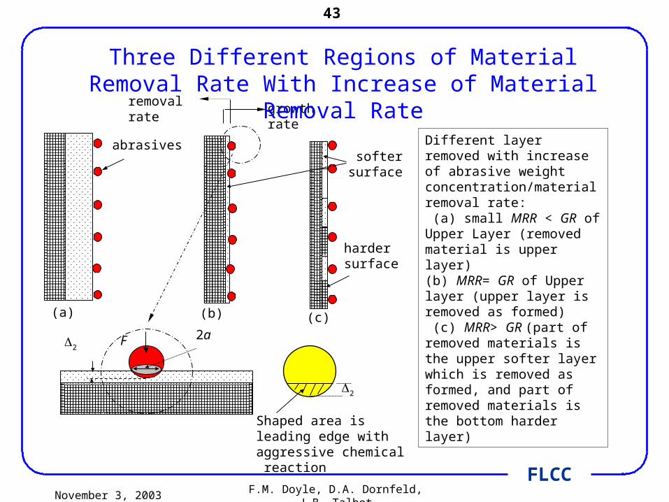
Different layer removed with increase of abrasive weight concentration/material removal rate: (a) small MRR < GR of Upper Layer (removed material is upper layer) (b) MRR= GR of Upper layer (upper layer is removed as formed) (c) MRR> GR (part of removed materials is the upper softer layer which is removed as formed, and part of removed materials is the bottom harder layer)
abrasives
growth rateremoval rate
F 2a2
(a) (b) (c)
2
Shaped area is leading edge with aggressive chemical reaction
softersurface
hardersurface
Three Different Regions of Material Removal Rate With Increase of Material Removal Rate

November 3, 2003 F.M. Doyle, D.A. Dornfeld, J.B. Talbot
44
FLCC
Process Modeling “Roadmap”
Particle-Scale Material Removal Model
Wafer-Scale Pressure and Velocity Distribution
Die-Scale Pressure Distribution Model
Consumable Parameters
Layout Density
Macroscopic Contact Mechanics Model (Weight Function)
Pattern Density Window and Effective Pattern Density
Material Removal Rate
Surface Quality
Die-Scale Topography (both vertical & lateral directions)
Upper Stream Wafer-Scale Topography
Wafer-Scale Topography Upper Stream
Die-Scale Topography
CMP Tool Configurations
Pattern Density Effect
Dishing Erosion
Dummy FillingCircuit PerformanceECAD
Include device design
November 3, 2003 F.M. Doyle, D.A. Dornfeld, J.B. Talbot
45
FLCC
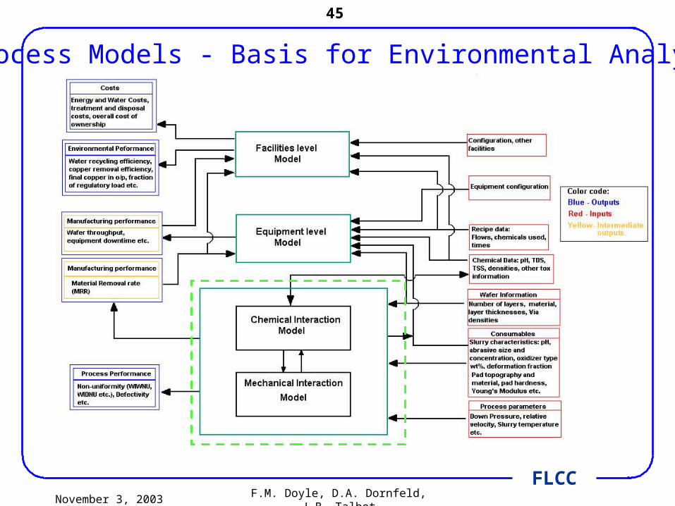
Process Models - Basis for Environmental Analysis
November 3, 2003 F.M. Doyle, D.A. Dornfeld, J.B. Talbot
46
FLCC
Future Work
November 3, 2003 F.M. Doyle, D.A. Dornfeld, J.B. Talbot
47
FLCC
Chemical and interfacial effectsCMP of heterogeneous surfaces
Characterize the effect of different slurry additives on the etching of copper when adjacent to diffusion barrier materials, advanced low-k dielectrics and other relevant phases
Explicitly consider autocatalytic effects, e.g. dissolved metal ions catalyzing decomposition of H2O2
Investigate the ability of different slurries to wet different phases, and the effect of surfactants in modifying wetting behavior
Consider coupling of chemical and mechanical phenomena through mechanisms such as: zeta potential modifications, hydration, dehydration, and sorption of species, particularly organic surfactants and polymers