Embed Size (px)
Citation preview
WI 030308.10
T 809
DRAFT NO. 4
DATE June 28, 2006 TAPPI
WORKING GROUP CHAIRMAN WO Kroeschell
SUBJECT CATEGORY FISCOTEC
RELATED METHODS See “Additional Information”
Approved by the Standard Specific Interest Group for this Test Method
TAPPI
CAUTION: This Test Method may include safety precautions which are believed to be appropriate at the time of publication of the method. The intent of these is to alert the user of the method to safety issues related to such use. The user is responsible for determining that the safety precautions are complete and are appropriate to their use of the method, and for ensuring that suitable safety practices have not changed since publication of the method. This method may require the use, disposal, or both, of chemicals which may present serious health hazards to humans. Procedures for the handling of such substances are set forth on Material Safety Data Sheets which must be developed by all manufacturers and importers of potentially hazardous chemicals and maintained by all distributors of potentially hazardous chemicals. Prior to the use of this method, the user must determine whether any of the chemicals to be used or disposed of are potentially hazardous and, if so, must follow strictly the procedures specified by both the manufacturer, as well as local, state, and federal authorities for safe use and disposal of these chemicals.
Flat crush of corrugating medium (CMT test) (Proposed revision of T 809 om-99)
(Lines in text or margins indicate changes since last draft)
1. Scope
This method describes a procedure for measuring the crushing resistance of a laboratory fluted strip of corrugating
medium, and provides a means of estimating, in the laboratory, the potential flat crush resistance of a corrugated board.
Other grades may not correlate with their potential.
NOTE 1: While the choice of testing instrument does not create significant differences in this test, it should be noted that when the flat crush
of the corrugated board is being determined, the rigid support instrument ( T 825) gives significantly higher results than the flexible
beam instrument (T 808).

2. Significance
Rigidity of the fluted structure is one of the essential characteristics of corrugated board and flat crush resistance (T 825)
is necessary to prevent crushing of the flute structure on the corrugator and other converting equipment. The corrugating
medium test (CMT) permits the evaluation of corrugating medium before it is fabricated into combined board, and may
by consideration of the flat crush of the corrugated board produced as a basis for judgment of fabrication efficiency.
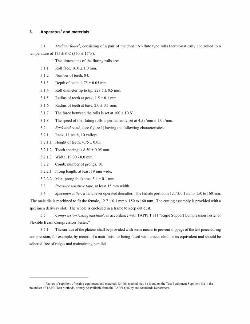
3. Apparatus1 and materials
3.1 Medium fluter1, consisting of a pair of matched “A”-flute type rolls thermostatically controlled to a
temperature of 177 ± 8°C (350 ± 15°F).
The dimensions of the fluting rolls are:
3.1.1 Roll face, 16.0 ± 1.0 mm (0.63 ± 0.04 in.).
3.1.2 Number of teeth, 84.
3.1.3 Depth of teeth, 4.75 ± 0.05 mm (0.2 ± 0.002 in.).
3.1.4 Roll diameter tip to tip, 228.5 ± 0.5 mm (9 ± 0.02 in.).
3.1.5 Radius of teeth at peak, 1.5 ± 0.1 mm (0.06 ± 0.004 in.).
3.1.6 Radius of teeth at base, 2.0 ± 0.1 mm (0.08 ± 0.004 in.).
3.1.7 The force between the rolls is set at 100 ± 10 N (22.5 ± 2.25 lbf.).
3.1.8 The speed of the fluting rolls is permanently set at 4.5 r/min ± 1.0 r/min.
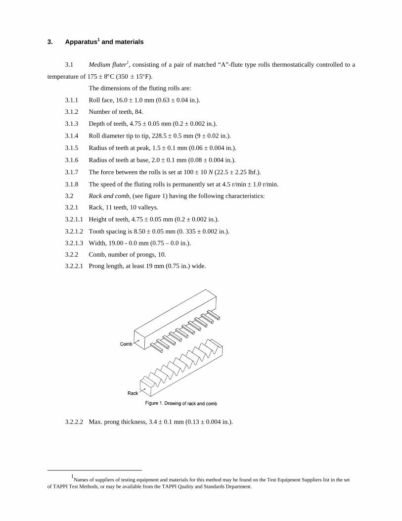
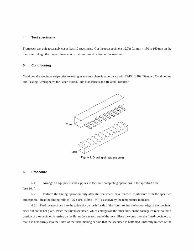
3.2 Rack and comb, (see figure 1) having the following characteristics:
Fig. 1. Drawing of rack and comb.
3.2.1 Rack, 11 teeth, 10 valleys.
1
Names of suppliers of testing equipment and materials for this method may be found on the Test Equipment Suppliers list in the set of TAPPI Test Methods, or may be available from the TAPPI Quality and Standards Department.
3.2.1.1 Height of teeth, 4.75 ± 0.05 mm (0.2 ± 0.002 in.).
3.2.1.2 Tooth spacing is 8.50 ± 0.05 mm (0. 335 ± 0.002 in.).
3.2.1.3 Width, 19.00 - 0.0 mm (0.75 – 0.0 in.).
3.2.2 Comb, number of prongs, 10.
3.2.2.1 Prong length, at least 19 mm (0.75 in.) wide.Max. prong thickness, 3.4 ± 0.1 mm (0.13 ± 0.004 in.).
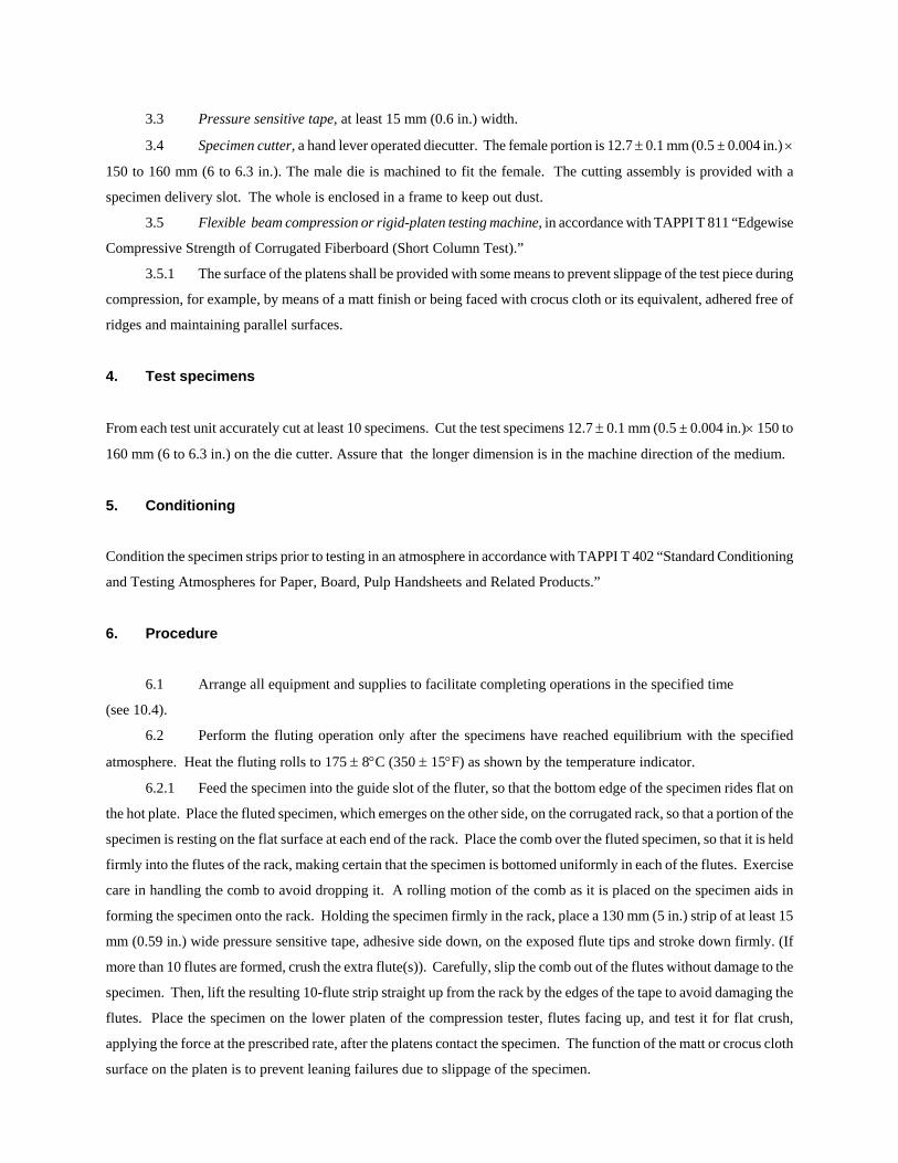
3.3 Pressure sensitive tape, at least 15 mm (0.6 in.) width.
3.4 Specimen cutter, a hand lever operated diecutter. The female portion is 12.7 ± 0.1 mm (0.5 ± 0.004 in.) ×
150 to 160 mm (6 to 6.3 in.). The male die is machined to fit the female. The cutting assembly is provided with a
specimen delivery slot. The whole is enclosed in a frame to keep out dust.
3.5 Flexible beam compression or rigid-platen testing machine, in accordance with TAPPI T 811 “Edgewise
Compressive Strength of Corrugated Fiberboard (Short Column Test).”
3.5.1 The surface of the platens shall be provided with some means to prevent slippage of the test piece during
compression, for example, by means of a matt finish or being faced with crocus cloth or its equivalent, adhered free of
ridges and maintaining parallel surfaces.
4. Test specimens
From each test unit accurately cut at least 10 specimens. Cut the test specimens 12.7 ± 0.1 mm (0.5 ± 0.004 in.) ×150 to
160 mm (6 to 6.3 in.) on the die cutter. Assure that the longer dimension is in the machine direction of the medium.
5. Conditioning
Condition the specimen strips prior to testing in an atmosphere in accordance with TAPPI T 402 “Standard Conditioning
and Testing Atmospheres for Paper, Board, Pulp Handsheets and Related Products.”
6. Procedure
6.1 Arrange all equipment and supplies to facilitate completing operations in the specified time
(see 10.4).
6.2 Perform the fluting operation only after the specimens have reached equilibrium with the specified
atmosphere. Heat the fluting rolls to 177 ± 8°C (350 ± 15°F) as shown by the temperature indicator.
6.2.1 Feed the specimen into the guide slot of the fluter, so that the bottom edge of the specimen rides flat on
the hot plate. Place the fluted specimen, which emerges on the other side, on the corrugated rack, so that a portion of the
specimen is resting on the flat surface at each end of the rack. Place the comb over the fluted specimen, so that it is held
firmly into the flutes of the rack, making certain that the specimen is bottomed uniformly in each of the flutes. Exercise
care in handling the comb to avoid dropping it. A rolling motion of the comb as it is placed on the specimen aids in
forming the specimen onto the rack. Holding the specimen firmly in the rack, place a 130 mm (5 in.) strip of at least 15
mm (0.59 in.) wide pressure sensitive tape, adhesive side down, on the exposed flute tips and stroke down firmly. [If
more than 10 flutes are formed, crush the extra flute(s)]. Carefully, slip the comb out of the flutes without damage to the
specimen. Then, lift the resulting 10-flute strip straight up from the rack by the edges of the tape to avoid damaging the

flutes. Place the specimen on the lower platen of the compression tester, flutes facing up, and test it for flat crush,
applying the force at the prescribed rate, after the platens contact the specimen. The function of the matt or crocus cloth
surface on the platen is to prevent leaning failures due to slippage of the specimen.
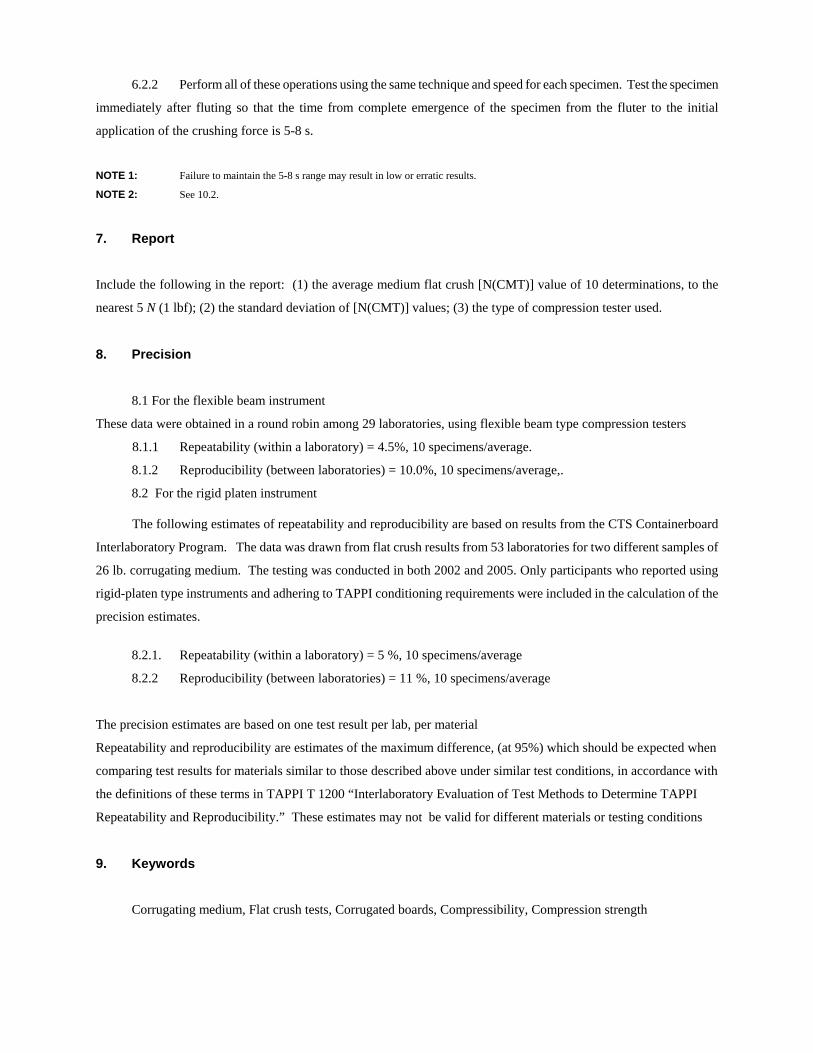
6.2.2 Perform all of these operations using the same technique and speed for each specimen. Test the specimen
immediately after fluting so that the time from complete emergence of the specimen from the fluter to the initial
application of the crushing force is 5-8 s.
NOTE 2: Failure to maintain the 5-8 s range may result in low or erratic results.
NOTE 3: See 10.2.
7. Report
Include the following in the report: (1) the average medium flat crush [N(CMT)] value of 10 determinations, to the
nearest 5 N (1 lbf); (2) the standard deviation of [N(CMT)] values; (3) the type of compression tester used.
8. Precision
8.1 For the flexible beam instrument
These data were obtained in a round robin among 29 laboratories, using flexible beam type compression testers
8.1.1 Repeatability (within a laboratory) = 4.5%, 10 specimens/average.
8.1.2 Reproducibility (between laboratories) = 10.0%, 10 specimens/average,. 8.2 For the rigid platen instrument The following estimates of repeatability and reproducibility are based on results from the CTS Containerboard
Interlaboratory Program. The data was drawn from flat crush results from 53 laboratories for two different samples of
26 lb. corrugating medium. The testing was conducted in both 2002 and 2005. Only participants who reported using
rigid-platen type instruments and adhering to TAPPI conditioning requirements were included in the calculation of the
precision estimates.
8.2.1. Repeatability (within a laboratory) = 5 %, 10 specimens/average
8.2.2 Reproducibility (between laboratories) = 11 %, 10 specimens/average
The precision estimates are based on one test result per lab, per material
Repeatability and reproducibility are estimates of the maximum difference, (at 95%) which should be expected when
comparing test results for materials similar to those described above under similar test conditions, in accordance with
the definitions of these terms in TAPPI T 1200 “Interlaboratory Evaluation of Test Methods to Determine TAPPI
Repeatability and Reproducibility.” These estimates may not be valid for different materials or testing conditions
9. Keywords
Corrugating medium, Flat crush tests, Corrugated boards, Compressibility, Compression strength
10. Additional information
10.1 Effective date of issue: to be assigned.
10.2 Another procedure has received wide use. After lifting the composite test piece from the rack, let it
condition in the testing atmosphere for 32.5 ± 2.5 min (30 to 35 min) before placing on the lower platen of the
compression apparatus, and test it for its flat crush resistance according to the procedure in 6.2. The precision of this
procedure is unknown.
10.3 Reflecting the number of equipment units currently in widespread use, the equipment specifications
indicated are soft conversions to metric units for the prior specifications of TAPPI T 809 “Flat Crush Potential of
Corrugating Medium (CMT Test).”
10.4 For most reliable results, the time for specimen preparation must be maintained within the 5-8 s time limit
specified. This is the time interval from the discharge of the fluted specimen from the fluter to the initial application of
force in the compression tester. To readily achieve this, the following suggestions have been found convenient:
10.4.1 The compression tester should be equipped with an automatic stop or limit switch to control the initial
clearance between the platens to a minimum, convenient for insertion of the specimen.
10.4.2 Mount the test equipment on the laboratory bench top, so that it is in a convenient position. For a right
handed tester this would be: left to right facing the equipment, fluter, comb and rack, and compression tester with
approximately 250 mm (10 in.) spacing between units.
10.4.3 Precut tape strips to proper length and adhere one end lightly to edge of bench.
10.4.4 Insert medium specimen into fluter with left hand.
10.4.5 Pick up comb with left hand.
10.4.6 Remove fluted specimen from fluter with right hand and place specimen on rack.
10.4.7 Holding comb in left hand, securely position fluted medium in rack.
10.4.8 Apply tape with right hand, using thumb to crush additional flutes at each end of the 10 flute test strip.
10.4.9 Remove comb carefully from taped specimen with left hand, holding specimen in reach with right hand.
10.4.10 Use right hand to insert specimen into compression tester plates.
NOTE 4: For a left handed tester much of the above procedure would be reversed.
10.4.11 Start compression tester with left hand on switch, or use foot pedal if unit is so equipped.
10.4.12 Return compression tester platens to initial position at completion of test.
10.5 Related methods: ISO 7263-1994 (E) two procedures, immediate testing (15 ± 3 s after commencement
of fluting), or 30 min reconditioning of fluted sample moisture content prior to compression test.
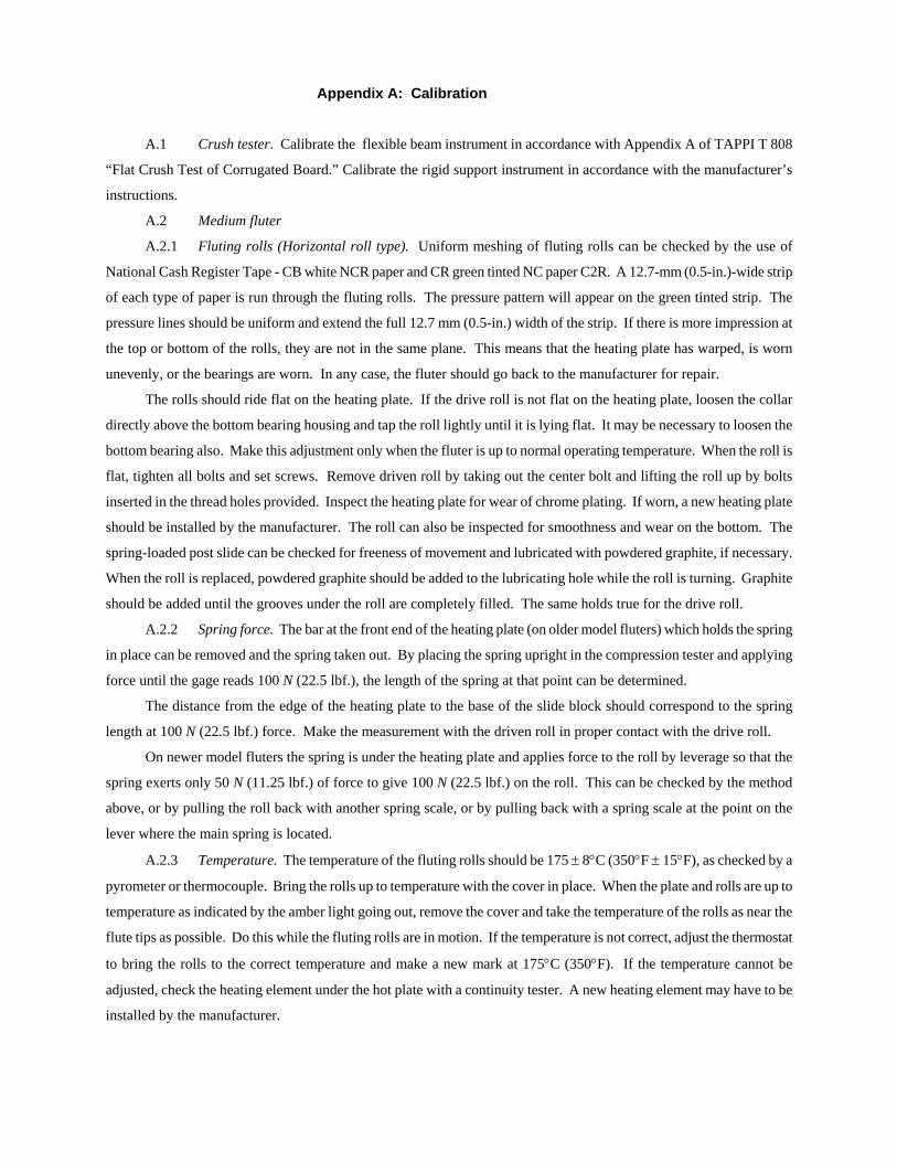
Appendix A: Calibration
A.1 Crush tester. Calibrate the flexible beam instrument in accordance with Appendix A of TAPPI T 808
“Flat Crush Test of Corrugated Board.” Calibrate the rigid support instrument in accordance with the manufacturer’s
instructions.
A.2 Medium fluter
A.2.1 Fluting rolls (Horizontal roll type). Uniform meshing of fluting rolls can be checked by the use of
National Cash Register Tape - CB white NCR paper and CR green tinted NC paper C2R. A 12.7-mm (0.5-in.)-wide strip
of each type of paper is run through the fluting rolls. The pressure pattern will appear on the green tinted strip. The
pressure lines should be uniform and extend the full 12.7 mm (0.5-in.) width of the strip. If there is more impression at
the top or bottom of the rolls, they are not in the same plane. This means that the heating plate has warped, is worn
unevenly, or the bearings are worn. In any case, the fluter should go back to the manufacturer for repair.
The rolls should ride flat on the heating plate. If the drive roll is not flat on the heating plate, loosen the collar
directly above the bottom bearing housing and tap the roll lightly until it is lying flat. It may be necessary to loosen the
bottom bearing also. Make this adjustment only when the fluter is up to normal operating temperature. When the roll is
flat, tighten all bolts and set screws. Remove driven roll by taking out the center bolt and lifting the roll up by bolts
inserted in the thread holes provided. Inspect the heating plate for wear of chrome plating. If worn, a new heating plate
should be installed by the manufacturer. The roll can also be inspected for smoothness and wear on the bottom. The
spring-loaded post slide can be checked for freeness of movement and lubricated with powdered graphite, if necessary.
When the roll is replaced, powdered graphite should be added to the lubricating hole while the roll is turning. Graphite
should be added until the grooves under the roll are completely filled. The same holds true for the drive roll.
A.2.2 Spring force. The bar at the front end of the heating plate (on older model fluters) which holds the spring
in place can be removed and the spring taken out. By placing the spring upright in the compression tester and applying
force until the gage reads 100 N (22.5 lbf), the length of the spring at that point can be determined.
The distance from the edge of the heating plate to the base of the slide block should correspond to the spring
length at 100 N (22.5 lbf) force. Make the measurement with the driven roll in proper contact with the drive roll.
On newer model fluters the spring is under the heating plate and applies force to the roll by leverage so that the
spring exerts only 50 N (11.25 lbf) of force to give 100 N (22.5 lbf) on the roll. This can be checked by the method
above, or by pulling the roll back with another spring scale, or by pulling back with a spring scale at the point on the
lever where the main spring is located.
A.2.3 Temperature. The temperature of the fluting rolls should be 177 ± 8°C (350°F ± 15°F), as checked by a
pyrometer or thermocouple. Bring the rolls up to temperature with the cover in place. When the plate and rolls are up to
temperature as indicated by the amber light going out, remove the cover and take the temperature of the rolls as near the
flute tips as possible. Do this while the fluting rolls are in motion. If the temperature is not correct, adjust the thermostat
to bring the rolls to the correct temperature and make a new mark at 177°C (350°F). If the temperature cannot be
adjusted, check the heating element under the hot plate with a continuity tester. A new heating element may have to be
installed by the manufacturer.

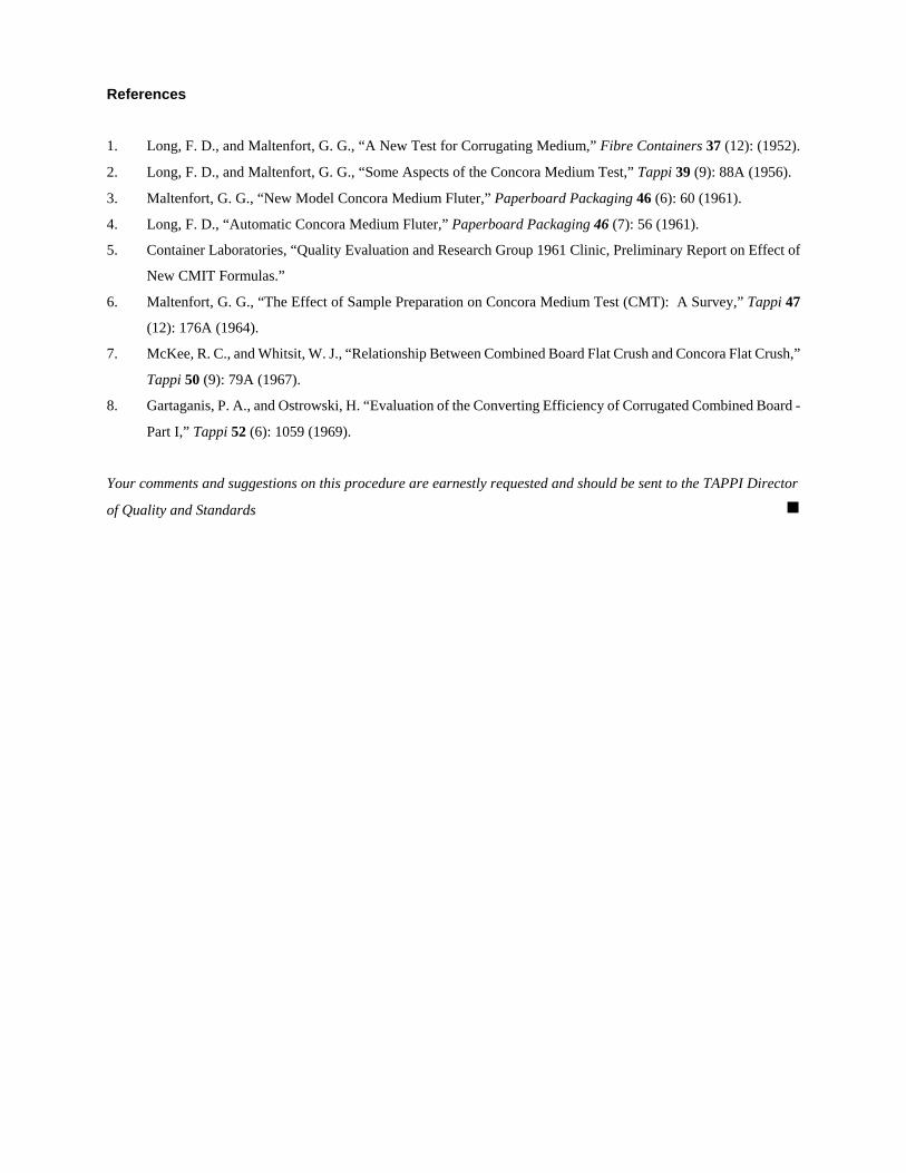
References
1. Long, F. D., and Maltenfort, G. G., “A New Test for Corrugating Medium,” Fibre Containers 37 (12): (1952).
2. Long, F. D., and Maltenfort, G. G., “Some Aspects of the Concora Medium Test,” Tappi 39 (9): 88A (1956).
3. Maltenfort, G. G., “New Model Concora Medium Fluter,” Paperboard Packaging 46 (6): 60 (1961).
4. Long, F. D., “Automatic Concora Medium Fluter,” Paperboard Packaging 46 (7): 56 (1961).
5. Container Laboratories, “Quality Evaluation and Research Group 1961 Clinic, Preliminary Report on Effect of
New CMIT Formulas.”
6. Maltenfort, G. G., “The Effect of Sample Preparation on Concora Medium Test (CMT): A Survey,” Tappi 47
(12): 176A (1964).
7. McKee, R. C., and Whitsit, W. J., “Relationship Between Combined Board Flat Crush and Concora Flat Crush,”
Tappi 50 (9): 79A (1967).
8. Gartaganis, P. A., and Ostrowski, H. “Evaluation of the Converting Efficiency of Corrugated Combined Board -
Part I,” Tappi 52 (6): 1059 (1969).
Your comments and suggestions on this procedure are earnestly requested and should be sent to the TAPPI Director
of Quality and Standards g
William O. Kroeschell 272 Mooring Line Drive Naples, Fl 34102-4741
(239) 262-6639
April 10, 2006 Dear T 809 SSIG member: Here is T 809 again. On the last ballot we had one negative vote and this was based on he voter’s belief that there was no significant difference between the results for the flexible beam and the rigid platen instruments. We checked and he was right. So we recombined the two methods back in to one and obtained new precision data for the rigid platen instrument, courtesy of Chris Czyryca and the Collaborative Testing Service. The new additions are underlined on this draft. We entered soft conversions of all the dimensions in the apparatus section, eliminated the 26# limit from the scope, removed the data tables estimating flat crush from the CMT, added a section describing the European method of conditioning before testing and took out the paragraph, which said that there were differences. We trust that all of these changes will meet with your approval. Also, we had thought about separating the rigid support method into a separate method, but that idea has been dropped. So those of you who indicated that you wanted to be on that SSIG, but were not on the SSIG for T 809, have now been added to the T 809 SSIG.
Yours very truly,
William O. Kroeschell
WI 030308.10
T 809
DRAFT NO. 3
DATE April 10, 2006 TAPPI
WORKING GROUP CHAIRMAN WO Kroeschell
SUBJECT CATEGORY FISCOTEC
RELATED METHODS See “Additional Information”
CAUTION: This Test Method may include safety precautions which are believed to be appropriate at the time of publication of the method. The intent of these is to alert the user of the method to safety issues related to such use. The user is responsible for determining that the safety precautions are complete and are appropriate to their use of the method, and for ensuring that suitable safety practices have not changed since publication of the method. This method may require the use, disposal, or both, of chemicals which may present serious health hazards to humans. Procedures for the handling of such substances are set forth on Material Safety Data Sheets which must be developed by all manufacturers and importers of potentially hazardous chemicals and maintained by all distributors of potentially hazardous chemicals. Prior to the use of this method, the user must determine whether any of the chemicals to be used or disposed of are potentially hazardous and, if so, must follow strictly the procedures specified by both the manufacturer, as well as local, state, and federal authorities for safe use and disposal of these chemicals.
Flat crush of corrugating medium (CMT test) (Proposed revision of T 809 om-99)
(Lines in text or margins indicate changes since last draft)
1. Scope
This method describes a procedure for measuring the crushing resistance of a laboratory fluted strip of corrugating
medium, and provides a means of estimating, in the laboratory, the potential flat crush resistance of a corrugated board.
Other grades may not correlate with their potential.
2. Significance
Rigidity of the fluted structure is one of the essential characteristics of corrugated board and flat crush resistance (T 825)
is necessary to prevent crushing of the flute structure on the corrugator and other converting equipment. The corrugating
medium test (CMT) permits the evaluation of corrugating medium before it is fabricated into combined board, and may
by consideration of the flat crush of the corrugated board produced as a basis for judgment of fabrication efficiency.
3. Apparatus1 and materials
3.1 Medium fluter1, consisting of a pair of matched “A”-flute type rolls thermostatically controlled to a
temperature of 175 ± 8°C (350 ± 15°F).
The dimensions of the fluting rolls are:
3.1.1 Roll face, 16.0 ± 1.0 mm (0.63 ± 0.04 in.).
3.1.2 Number of teeth, 84.
3.1.3 Depth of teeth, 4.75 ± 0.05 mm (0.2 ± 0.002 in.).
3.1.4 Roll diameter tip to tip, 228.5 ± 0.5 mm (9 ± 0.02 in.).
3.1.5 Radius of teeth at peak, 1.5 ± 0.1 mm (0.06 ± 0.004 in.).
3.1.6 Radius of teeth at base, 2.0 ± 0.1 mm (0.08 ± 0.004 in.).
3.1.7 The force between the rolls is set at 100 ± 10 N (22.5 ± 2.25 lbf.).
3.1.8 The speed of the fluting rolls is permanently set at 4.5 r/min ± 1.0 r/min.
3.2 Rack and comb, (see figure 1) having the following characteristics:
3.2.1 Rack, 11 teeth, 10 valleys.
3.2.1.1 Height of teeth, 4.75 ± 0.05 mm (0.2 ± 0.002 in.).
3.2.1.2 Tooth spacing is 8.50 ± 0.05 mm (0. 335 ± 0.002 in.).
3.2.1.3 Width, 19.00 - 0.0 mm (0.75 – 0.0 in.).
3.2.2 Comb, number of prongs, 10.
3.2.2.1 Prong length, at least 19 mm (0.75 in.) wide.
3.2.2.2 Max. prong thickness, 3.4 ± 0.1 mm (0.13 ± 0.004 in.).
1
Names of suppliers of testing equipment and materials for this method may be found on the Test Equipment Suppliers list in the set of TAPPI Test Methods, or may be available from the TAPPI Quality and Standards Department.
3.3 Pressure sensitive tape, at least 15 mm (0.6 in.) width.
3.4 Specimen cutter, a hand lever operated diecutter. The female portion is 12.7 ± 0.1 mm (0.5 ± 0.004 in.) ×
150 to 160 mm (6 to 6.3 in.). The male die is machined to fit the female. The cutting assembly is provided with a
specimen delivery slot. The whole is enclosed in a frame to keep out dust.
3.5 Flexible beam compression or rigid-platen testing machine, in accordance with TAPPI T 811 “Edgewise
Compressive Strength of Corrugated Fiberboard (Short Column Test).”
3.5.1 The surface of the platens shall be provided with some means to prevent slippage of the test piece during
compression, for example, by means of a matt finish or being faced with crocus cloth or its equivalent, adhered free of
ridges and maintaining parallel surfaces.
4. Test specimens
From each test unit accurately cut at least 10 specimens. Cut the test specimens 12.7 ± 0.1 mm (0.5 ± 0.004 in.)× 150 to
160 mm (6 to 6.3 in.) on the die cutter. Assure that the longer dimension is in the machine direction of the medium.
5. Conditioning
Condition the specimen strips prior to testing in an atmosphere in accordance with TAPPI T 402 “Standard Conditioning
and Testing Atmospheres for Paper, Board, Pulp Handsheets and Related Products.”
6. Procedure
6.1 Arrange all equipment and supplies to facilitate completing operations in the specified time
(see 10.4).
6.2 Perform the fluting operation only after the specimens have reached equilibrium with the specified
atmosphere. Heat the fluting rolls to 175 ± 8°C (350 ± 15°F) as shown by the temperature indicator.
6.2.1 Feed the specimen into the guide slot of the fluter, so that the bottom edge of the specimen rides flat on
the hot plate. Place the fluted specimen, which emerges on the other side, on the corrugated rack, so that a portion of the
specimen is resting on the flat surface at each end of the rack. Place the comb over the fluted specimen, so that it is held
firmly into the flutes of the rack, making certain that the specimen is bottomed uniformly in each of the flutes. Exercise
care in handling the comb to avoid dropping it. A rolling motion of the comb as it is placed on the specimen aids in
forming the specimen onto the rack. Holding the specimen firmly in the rack, place a 130 mm (5 in.) strip of at least 15
mm (0.59 in.) wide pressure sensitive tape, adhesive side down, on the exposed flute tips and stroke down firmly. (If
more than 10 flutes are formed, crush the extra flute(s)). Carefully, slip the comb out of the flutes without damage to the
specimen. Then, lift the resulting 10-flute strip straight up from the rack by the edges of the tape to avoid damaging the
flutes. Place the specimen on the lower platen of the compression tester, flutes facing up, and test it for flat crush,
applying the force at the prescribed rate, after the platens contact the specimen. The function of the matt or crocus cloth
surface on the platen is to prevent leaning failures due to slippage of the specimen.
6.2.2 Perform all of these operations using the same technique and speed for each specimen. Test the specimen
immediately after fluting so that the time from complete emergence of the specimen from the fluter to the initial
application of the crushing force is 5-8 s.
NOTE 1: Failure to maintain the 5-8 s range may result in low or erratic results.
NOTE 2: See 10.2.
7. Report
Include the following in the report: (1) the average medium flat crush [N(CMT)] value of 10 determinations, to the
nearest 5 N (1 lbf); (2) the standard deviation of [N(CMT)] values; (3) the type of compression tester used.
8. Precision
8.1 For the flexible beam instrument
These data were obtained in a round robin among 29 laboratories, using flexible beam type compression testers
8.1.1 Repeatability (within a laboratory) = 4.5%, 10 specimens/average.
8.1.2 Reproducibility (between laboratories) = 10.0%, 10 specimens/average,. 8.2 For the rigid platen instrument The following estimates of repeatability and reproducibility are based on results from the CTS Containerboard
Interlaboratory Program. The data was drawn from flat crush results from 53 laboratories for two different samples of
26 lb. corrugating medium. The testing was conducted in both 2002 and 2005. Only participants who reported using
rigid-platen type instruments and adhering to TAPPI conditioning requirements were included in the calculation of the
precision estimates.
8.2.1. Repeatability (within a laboratory) = 5 %, 10 specimens/average
8.2.2 Reproducibility (between laboratories) = 11 %, 10 specimens/average
The precision estimates are based on one test result per lab, per material
Repeatability and reproducibility are estimates of the maximum difference, (at 95%) which should be expected when
comparing test results for materials similar to those described above under similar test conditions, in accordance with
the definitions of these terms in TAPPI T 1200 “Interlaboratory Evaluation of Test Methods to Determine TAPPI
Repeatability and Reproducibility.” These estimates may not be valid for different materials or testing conditions
9. Keywords
Corrugating medium, Flat crush tests, Corrugated boards, Compressibility, Compression strength

10. Additional information
10.1 Effective date of issue: to be assigned.
10.2 Another procedure has received wide use. After lifting the composite test piece from the rack, let it
condition in the testing atmosphere for 32.5 ± 2.5 min (30 to 35 min) before placing on the lower platen of the
compression apparatus, and test it for its flat crush resistance according to the procedure in 6.2. The precision of this
procedure is unknown.
10.3 Reflecting the number of equipment units currently in widespread use, the equipment specifications
indicated are soft conversions to metric units for the prior specifications of TAPPI T 809 “Flat Crush Potential of
Corrugating Medium (CMT Test).”
10.4 For most reliable results, the time for specimen preparation must be maintained within the 5-8 s time limit
specified. This is the time interval from the discharge of the fluted specimen from the fluter to the initial application of
force in the compression tester. To readily achieve this, the following suggestions have been found convenient:
10.4.1 The compression tester should be equipped with an automatic stop or limit switch to control the initial
clearance between the platens to a minimum, convenient for insertion of the specimen.
10.4.2 Mount the test equipment on the laboratory bench top, so that it is in a convenient position. For a right
handed tester this would be: left to right facing the equipment, fluter, comb and rack, and compression tester with
approximately 250 mm (10 in.) spacing between units.
10.4.3 Precut tape strips to proper length and adhere one end lightly to edge of bench.
10.4.4 Insert medium specimen into fluter with left hand.
10.4.5 Pick up comb with left hand.
10.4.6 Remove fluted specimen from fluter with right hand and place specimen on rack.
10.4.7 Holding comb in left hand, securely position fluted medium in rack.
10.4.8 Apply tape with right hand, using thumb to crush additional flutes at each end of the 10 flute test strip.
10.4.9 Remove comb carefully from taped specimen with left hand, holding specimen in reach with right hand.
10.4.10 Use right hand to insert specimen into compression tester plates.
NOTE 3: For a left handed tester much of the above procedure would be reversed.
10.4.11 Start compression tester with left hand on switch, or use foot pedal if unit is so equipped.
10.4.12 Return compression tester platens to initial position at completion of test.
10.5 Related methods: ISO 7263-1994 (E) two procedures, immediate testing (15 ± 3s after commencement
of fluting), or 30 min reconditioning of fluted sample moisture content prior to compression test.
Appendix A: Calibration
A.1 Crush tester. Calibrate the flexible beam instrument in accordance with Appendix A of TAPPI T 808
“Flat Crush Test of Corrugated Board.” Calibrate the rigid support instrument in accordance with the manufacturer’s
instructions.
A.2 Medium fluter
A.2.1 Fluting rolls (Horizontal roll type). Uniform meshing of fluting rolls can be checked by the use of
National Cash Register Tape - CB white NCR paper and CR green tinted NC paper C2R. A 12.7-mm (0.5-in.)-wide strip
of each type of paper is run through the fluting rolls. The pressure pattern will appear on the green tinted strip. The
pressure lines should be uniform and extend the full 12.7 mm (0.5-in.) width of the strip. If there is more impression at
the top or bottom of the rolls, they are not in the same plane. This means that the heating plate has warped, is worn
unevenly, or the bearings are worn. In any case, the fluter should go back to the manufacturer for repair.
The rolls should ride flat on the heating plate. If the drive roll is not flat on the heating plate, loosen the collar
directly above the bottom bearing housing and tap the roll lightly until it is lying flat. It may be necessary to loosen the
bottom bearing also. Make this adjustment only when the fluter is up to normal operating temperature. When the roll is
flat, tighten all bolts and set screws. Remove driven roll by taking out the center bolt and lifting the roll up by bolts
inserted in the thread holes provided. Inspect the heating plate for wear of chrome plating. If worn, a new heating plate
should be installed by the manufacturer. The roll can also be inspected for smoothness and wear on the bottom. The
spring-loaded post slide can be checked for freeness of movement and lubricated with powdered graphite, if necessary.
When the roll is replaced, powdered graphite should be added to the lubricating hole while the roll is turning. Graphite
should be added until the grooves under the roll are completely filled. The same holds true for the drive roll.
A.2.2 Spring force. The bar at the front end of the heating plate (on older model fluters) which holds the spring
in place can be removed and the spring taken out. By placing the spring upright in the compression tester and applying
force until the gage reads 100 N (22.5 lbf.), the length of the spring at that point can be determined.
The distance from the edge of the heating plate to the base of the slide block should correspond to the spring
length at 100 N (22.5 lbf.) force. Make the measurement with the driven roll in proper contact with the drive roll.
On newer model fluters the spring is under the heating plate and applies force to the roll by leverage so that the
spring exerts only 50 N (11.25 lbf.) of force to give 100 N (22.5 lbf.) on the roll. This can be checked by the method
above, or by pulling the roll back with another spring scale, or by pulling back with a spring scale at the point on the
lever where the main spring is located.
A.2.3 Temperature. The temperature of the fluting rolls should be 175 ± 8°C (350°F ± 15°F), as checked by a
pyrometer or thermocouple. Bring the rolls up to temperature with the cover in place. When the plate and rolls are up to
temperature as indicated by the amber light going out, remove the cover and take the temperature of the rolls as near the
flute tips as possible. Do this while the fluting rolls are in motion. If the temperature is not correct, adjust the thermostat
to bring the rolls to the correct temperature and make a new mark at 175°C (350°F). If the temperature cannot be
adjusted, check the heating element under the hot plate with a continuity tester. A new heating element may have to be
installed by the manufacturer.
References
1. Long, F. D., and Maltenfort, G. G., “A New Test for Corrugating Medium,” Fibre Containers 37 (12): (1952).
2. Long, F. D., and Maltenfort, G. G., “Some Aspects of the Concora Medium Test,” Tappi 39 (9): 88A (1956).
3. Maltenfort, G. G., “New Model Concora Medium Fluter,” Paperboard Packaging 46 (6): 60 (1961).
4. Long, F. D., “Automatic Concora Medium Fluter,” Paperboard Packaging 46 (7): 56 (1961).
5. Container Laboratories, “Quality Evaluation and Research Group 1961 Clinic, Preliminary Report on Effect of
New CMIT Formulas.”
6. Maltenfort, G. G., “The Effect of Sample Preparation on Concora Medium Test (CMT): A Survey,” Tappi 47
(12): 176A (1964).
7. McKee, R. C., and Whitsit, W. J., “Relationship Between Combined Board Flat Crush and Concora Flat Crush,”
Tappi 50 (9): 79A (1967).
8. Gartaganis, P. A., and Ostrowski, H. “Evaluation of the Converting Efficiency of Corrugated Combined Board -
Part I,” Tappi 52 (6): 1059 (1969).
Your comments and suggestions on this procedure are earnestly requested and should be sent to the TAPPI Director
of Quality and Standards g
William O. Kroeschell 272 Mooring Line Drive Naples, Fl 34102-4741
(239) 262-6639
November 3, 2005 TO : SSIG for T 809 We decided to rewrite T 809 to take in all of the comments on the first draft in the following way: (Additions are underlined, eliminations struck through) We eliminated the rigid support tester from this draft. Don’t worry. We have already rewritten the new method for the rigid support tester and are in the process of developing a precision statement from the CTS data. It should be out shortly. Then there will be two methods just as we have for flat crush and many other methods. We took out the limit for 26 pound in the Scope and added a note about the European method, where they condition for 30 minutes before testing. We couldn’t do more with this because the precision is not known. Finally we took out the tables relating the results to flat crush. After all there was a disclaimer in 10.3 for this data anyway and it really didn’t contribute to the test method. I tried to get this out years ago. We trust that these changes still meet with your approval.
Yours very truly,
William O. Kroeschell
WI 030308.10
T 809
DRAFT NO. 2
DATE November 3, 2005 TAPPI
WORKING GROUP CHAIRMAN WO Kroeschell
SUBJECT CATEGORY FISCOTEC
RELATED METHODS See “Additional Information”
CAUTION: This Test Method may include safety precautions which are believed to be appropriate at the time of publication of the method. The intent of these is to alert the user of the method to safety issues related to such use. The user is responsible for determining that the safety precautions are complete and are appropriate to their use of the method, and for ensuring that suitable safety practices have not changed since publication of the method. This method may require the use, disposal, or both, of chemicals which may present serious health hazards to humans. Procedures for the handling of such substances are set forth on Material Safety Data Sheets which must be developed by all manufacturers and importers of potentially hazardous chemicals and maintained by all distributors of potentially hazardous chemicals. Prior to the use of this method, the user must determine whether any of the chemicals to be used or disposed of are potentially hazardous and, if so, must follow strictly the procedures specified by both the manufacturer, as well as local, state, and federal authorities for safe use and disposal of these chemicals.
Flat crush of corrugating medium (CMT test) (flexible beam tester)
(Five-year review of T 809 om-99) (lines in text or margins indicate changes since last draft)
1. Scope
This method describes a procedure for measuring the crushing resistance of a laboratory fluted strip of corrugating
medium, and provides a means of estimating, in the laboratory, the potential flat crush resistance of a corrugated board.
Other grades may not correlate with their potential.
2. Significance
Rigidity of the fluted structure is one of the essential characteristics of corrugated board and flat crush resistance is
necessary to prevent crushing of the flute structure on the corrugator and other converting equipment. The corrugating
medium test (CMT) permits the evaluation of corrugating medium before it is fabricated into combined board, and may
also be used as a basis for judgment of fabrication efficiency.
3. Apparatus1 and materials
3.1 Medium fluter1, consisting of a pair of matched “A”-flute type rolls thermostatically controlled to a
temperature of 175 ± 8°C (350 ± 15°F).
The dimensions of the fluting rolls are:
3.1.1 Roll face, 16.0 ± 1.0 mm.
3.1.2 Number of teeth, 84.
3.1.3 Depth of teeth, 4.75 ± 0.05 mm.
3.1.4 Roll diameter tip to tip, 228.5 ± 0.5 mm.
3.1.5 Radius of teeth at peak, 1.5 ± 0.1 mm.
3.1.6 Radius of teeth at base, 2.0 ± 0.1 mm.
3.1.7 The force between the rolls is set at 100 ± 10 N.
3.1.8 The speed of the fluting rolls is permanently set at 4.5 r/mm ± 1.0 r/mm.
3.2 Rack and comb, (see figure 1) having the following characteristics:
3.2.1 Rack, 11 teeth, 10 valleys.
3.2.1.1 Height of teeth, 4.75 ± 0.05.
3.2.1.2 Tooth spacing is 8.50 ± 0.05 mm.
3.2.1.3 Width, 19.00 - 0.0 mm.
3.2.2 Comb, number of prongs, 10.
3.2.2.1 Prong length, at least 19 mm wide.
3.2.2.2 Max. prong thickness, 3.4 ± 0.1 mm.
3.3 Pressure sensitive tape, at least 15 mm width.
3.4 Specimen cutter, a hand lever operated diecutter. The female portion is 12.7 ± 0.1 mm × 150 to 160 mm.
The male die is machined to fit the female, 12.7 ± 0.1 mm × 150 to 160 mm. The cutting assembly is provided with a
specimen delivery slot. The whole is enclosed in a frame to keep out dust.
3.5 Compression testing machine1, in accordance with TAPPI T 811 “Edgewise Compressive Strength of
Corrugated Fiberboard (Short Column Test).”
3.5.1 The surface of the platens shall be provided with some means to prevent slippage of the test piece during
compression, for example, by means of a matt finish or being faced with crocus cloth or its equivalent and should be
adhered free of ridges and maintaining parallel.
1
Names of suppliers of testing equipment and materials for this method may be found on the Test Equipment Suppliers list in the bound set of TAPPI Test Methods, or may be available from the TAPPI Quality and Standards Department.
4. Test specimens
From each test unit accurately cut at least 10 specimens. Cut the test specimens 12.7 ± 0.1 mm × 150 to 160 mm on the
die cutter. Align the longer dimension in the machine direction of the medium.
5. Conditioning
Condition the specimen strips prior to testing in an atmosphere in accordance with TAPPI T 402 “Standard Conditioning
and Testing Atmospheres for Paper, Board, Pulp Handsheets and Related Products.”
6. Procedure
6.1 Arrange all equipment and supplies to facilitate completing operations in the specified time
(see 10.4).
6.2 Perform the fluting operation only after the specimens have reached equilibrium with the specified
atmosphere. Heat the fluting rolls to 175 ± 8°C (350 ± 15°F) as shown by the temperature indicator.
6.2.1 Feed the specimen into the guide slot on the left side of the fluter, so that the bottom edge of the specimen
rides flat on the hot plate. Place the fluted specimen, which emerges on the other side, on the corrugated rack, so that a
portion of the specimen is resting on the flat surface at each end of the rack. Place the comb over the fluted specimen, so
that it is held firmly into the flutes of the rack, making certain that the specimen is bottomed uniformly in each of the
flutes. Exercise care in handling the comb to avoid dropping it. A rolling motion of the comb as it is placed on the
specimen aids in forming the specimen onto the rack. Holding the specimen firmly in the rack, place a 130-mm strip of
at least 15 mm wide pressure sensitive tape, adhesive side down, on the exposed flute tips and stroke down firmly. (If
more than 10 flutes are formed, crush the extra flute(s)). Carefully, slip the comb out of the flutes without damage to the
specimen. Then, lift the resulting 10-flute strip straight up from the rack by the edges of the tape to avoid damaging the
flutes. Place the specimen on the lower platen of the compression tester, flutes facing up, and test it for flat crush,
applying the force at the prescribed rate, after the platens contact the specimen. The function of the matt or crocus cloth
surface on the platen is to prevent leaning failures due to slippage of the specimen.
6.2.2 Perform all of these operations using the same technique and speed for each specimen. Test the specimen
immediately after fluting so that the time from complete emergence of the specimen from the fluter to the initial
application of the crushing force is 5-8 s.
NOTE 1: Failure to maintain the 5-8 s range may result in low or erratic results.
NOTE 2: See 10.2.
7. Report
Include the following in the report: (1) the average medium flat crush [N(CMT)] value of 10 determinations, to the
nearest 5 N (1 lbf); (2) the standard deviation of [N(CMT)] values; (3) the type of compression tester used.
8. Precision
8.1 Repeatability (within a laboratory) = 4.5%, 10 specimens/average.
8.2 Reproducibility (between laboratories) = 10.0%, 10 specimens/average, in accordance with the
definitions of these terms in TAPPI T 1206 “Precision Statement for Test Methods.”
8.3 These data were obtained in a round robin among 29 laboratories, using flexible beam type compression
testers.
8.4 Data contained in Reports 278 and 279 of the Collaborative Reference Program for Containerboard
indicate that the Rigid Platen Type Compression Testers yield results that are 1% higher than results obtained on
Flexible Beam Type instruments. The results from tests on 26 lb medium were averaged using data from twenty (20)
laboratories with Rigid Platen Testers and compared to data from thirty (30) laboratories with Flexible Beam Testers.
9. Keywords
Corrugating medium, Flat crush tests, Corrugated boards, Compressibility, Compression strength

10. Additional information
10.1 Effective date of issue: to be assigned.
10.2 Another procedure has received wide use. After lifting the composite test piece from the rack, let it
condition in the testing atmosphere for 32.5 ± 2.5 min (30 to 35 min) before placing on the lower platen of the
compression apparatus, and test it for its flat crush resistance according to the procedure in 6.2. The precision of this
procedure is unknown.
10.3 Reflecting the number of equipment units currently in widespread use, the equipment specifications
indicated are soft conversions to metric units for the prior specifications of TAPPI T 809 “Flat Crush Potential of
Corrugating Medium (CMT Test).”
10.4 For most reliable results, the time for specimen preparation must be maintained within the 5-8 s time limit
specified. This is the time interval from the discharge of the fluted specimen from the fluter to the initial application of
force in the compression tester. To readily achieve this, the following suggestions have been found convenient:
10.4.1 The compression tester should be equipped with an automatic stop or limit switch to control the initial
clearance between the platens to a minimum, convenient for insertion of the specimen.
10.4.2 Mount the test equipment on the laboratory bench top, so that it is in a convenient position. For a right
handed tester this would be: left to right facing the equipment, fluter, comb and rack, and compression tester with
approximately 250 mm (10 in.) spacing between units.
10.4.3 Precut tape strips to proper length and adhere one end lightly to edge of bench.
10.4.4 Insert medium specimen into fluter with left hand.
10.4.5 Pick up comb with left hand.
10.4.6 Remove fluted specimen from fluter with right hand and place specimen on rack.
10.4.7 Holding comb in left hand, securely position fluted medium in rack.
10.4.8 Apply tape with right hand, using thumb to crush additional flutes at each end of the 10 flute test strip.
10.4.9 Remove comb carefully from taped specimen with left hand, holding specimen in reach with right hand.
10.4.10 Use right hand to insert specimen into compression tester plates.
NOTE 3: For a left handed tester much of the above procedure would be reversed.
10.4.11 Start compression tester with left hand on switch, or use foot pedal if unit is so equipped.
10.4.12 Return compression tester platens to initial position at completion of test.
10.5 Related methods: ISO 7263-1994 (E) two procedures, immediate testing (15 ± 3s after commencement of
fluting), or 30 min reconditioning of fluted sample moisture content prior to compression test.

Appendix A: Calibration
A.1 Crush tester. Calibrate the flexible beam instrument in accordance with Appendix A of TAPPI T 808
“Flat Crush Test of Corrugated Board.” Calibrate the rigid support instrument in accordance with manufacturer's
instructions.
A.2 Medium fluter
A.2.1 Fluting rolls (Horizontal roll type). Uniform meshing of fluting rolls can be checked by the use of
National Cash Register Tape - CB white NCR paper and CR green tinted NC paper C2R. A 12.7-mm (0.5-in.)-wide strip
of each type of paper is run through the fluting rolls. The pressure pattern will appear on the green tinted strip. The
pressure lines should be uniform and extend the full 12.7 mm (0.5-in.) width of the strip. If there is more impression at
the top or bottom of the rolls, they are not in the same plane. This means that the heating plate has warped, is worn
unevenly, or the bearings are worn. In any case, the fluter should go back to the manufacturer for repair.
The rolls should ride flat on the heating plate. If the drive roll is not flat on the heating plate, loosen the collar
directly above the bottom bearing housing and tap the roll lightly until it is lying flat. It may be necessary to loosen the
bottom bearing also. Make this adjustment only when the fluter is up to normal operating temperature. When the roll is
flat, tighten all bolts and set screws. Remove driven roll by taking out the center bolt and lifting the roll up by bolts
inserted in the thread holes provided. Inspect the heating plate for wear of chrome plating. If worn, a new heating plate
should be installed by the manufacturer. The roll can also be inspected for smoothness and wear on the bottom. The
spring-loaded post slide can be checked for freeness of movement and lubricated with powdered graphite, if necessary.
When the roll is replaced, powdered graphite should be added to the lubricating hole while the roll is turning. Graphite
should be added until the grooves under the roll are completely filled. The same holds true for the drive roll.
A.2.2 Spring force. The bar at the front end of the heating plate (on older model fluters) which holds the spring
in place can be removed and the spring taken out. By placing the spring upright in the compression tester and applying
force until the gage reads 100 N (22.5 lb), the length of the spring at that point can be determined.
The distance from the edge of the heating plate to the base of the slide block should correspond to the spring
length at 100 N (22.5 lb) force. Make the measurement with the driven roll in proper contact with the drive roll.
On newer model fluters the spring is under the heating plate and applies force to the roll by leverage so that the
spring exerts only 50 N (11.25 lb) of force to give 100 N (22.5 lb) on the roll. This can be checked by the method above,
or by pulling the roll back with another spring scale, or by pulling back with a spring scale at the point on the lever where
the main spring is located.
A.2.3 Temperature. The temperature of the fluting rolls should be 175 ± 8°C (350°F ± 15°F), as checked by a
pyrometer or thermocouple. Bring the rolls up to temperature with the cover in place. When the plate and rolls are up to
temperature as indicated by the amber light going out, remove the cover and take the temperature of the rolls as near the
flute tips as possible. Do this while the fluting rolls are in motion. If the temperature is not correct, adjust the thermostat
to bring the rolls to the correct temperature and make a new mark at 175°C (350°F). If the temperature cannot be
adjusted, check the heating element under the hot plate with a continuity tester. A new heating element may have to be
installed by the manufacturer.
References
1. Long, F. D., and Maltenfort, G. G., “A New Test for Corrugating Medium,” Fibre Containers 37 (12): (1952).
2. Long, F. D., and Maltenfort, G. G., “Some Aspects of the Concora Medium Test,” Tappi 39 (9): 88A (1956).
3. Maltenfort, G. G., “New Model Concora Medium Fluter,” Paperboard Packaging 46 (6): 60 (1961).
4. Long, F. D., “Automatic Concora Medium Fluter,” Paperboard Packaging 46 (7): 56 (1961).
5. Container Laboratories, “Quality Evaluation and Research Group 1961 Clinic, Preliminary Report on Effect of
New CMIT Formulas.”
6. Maltenfort, G. G., “The Effect of Sample Preparation on Concora Medium Test (CMT): A Survey,” Tappi 47
(12): 176A (1964).
7. McKee, R. C., and Whitsit, W. J., “Relationship Between Combined Board Flat Crush and Concora Flat Crush,”
Tappi 50 (9): 79A (1967).
8. Gartaganis, P. A., and Ostrowski, H. “Evaluation of the Converting Efficiency of Corrugated Combined Board -
Part I,” Tappi 52 (6): 1059 (1969).
Your comments and suggestions on this procedure are earnestly requested and should be sent to the TAPPI Director
of Quality and Standards. g
WI 030308.10
T 809
DRAFT NO. 1
DATE August 21, 2003 TAPPI
WORKING GROUP CHAIRMAN to be assigned
SUBJECT CATEGORY FISCOTEC
RELATED METHODS See “Additional Information”
CAUTION: This Test Method may include safety precautions which are believed to be appropriate at the time of publication of the method. The intent of these is to alert the user of the method to safety issues related to such use. The user is responsible for determining that the safety precautions are complete and are appropriate to their use of the method, and for ensuring that suitable safety practices have not changed since publication of the method. This method may require the use, disposal, or both, of chemicals which may present serious health hazards to humans. Procedures for the handling of such substances are set forth on Material Safety Data Sheets which must be developed by all manufacturers and importers of potentially hazardous chemicals and maintained by all distributors of potentially hazardous chemicals. Prior to the use of this method, the user must determine whether any of the chemicals to be used or disposed of are potentially hazardous and, if so, must follow strictly the procedures specified by both the manufacturer, as well as local, state, and federal authorities for safe use and disposal of these chemicals.
Flat crush of corrugating medium (CMT test) (Five-year review of T 809 om-99)
1. Scope
This method describes a procedure for measuring the crushing resistance of a laboratory fluted strip of 26 pound
corrugating medium, and provides a means of estimating, in the laboratory, the potential flat crush resistance of a
corrugated board. Other grades may not correlate with their potential.
2. Significance
Rigidity of the fluted structure is one of the essential characteristics of corrugated board and flat crush resistance is
necessary to prevent crushing of the flute structure on the corrugator and other converting equipment. The corrugating
medium test (CMT) permits the evaluation of corrugating medium before it is fabricated into combined board, and may
also be used as a basis for judgment of fabrication efficiency.
3. Apparatus1 and materials
3.1 Medium fluter1, consisting of a pair of matched “A”-flute type rolls thermostatically controlled to a
temperature of 175 ± 8°C (350 ± 15°F).
The dimensions of the fluting rolls are:
3.1.1 Roll face, 16.0 ± 1.0 mm.
3.1.2 Number of teeth, 84.
3.1.3 Depth of teeth, 4.75 ± 0.05 mm.
3.1.4 Roll diameter tip to tip, 228.5 ± 0.5 mm.
3.1.5 Radius of teeth at peak, 1.5 ± 0.1 mm.
3.1.6 Radius of teeth at base, 2.0 ± 0.1 mm.
3.1.7 The force between the rolls is set at 100 ± 10 N.
3.1.8 The speed of the fluting rolls is permanently set at 4.5 r/mm ± 1.0 r/mm.
3.2 Rack and comb, (see figure 1) having the following characteristics:
3.2.1 Rack, 11 teeth, 10 valleys.
3.2.1.1 Height of teeth, 4.75 ± 0.05.
3.2.1.2 Tooth spacing is 8.50 ± 0.05 mm.
3.2.1.3 Width, 19.00 - 0.0 mm.
3.2.2 Comb, number of prongs, 10.
3.2.2.1 Prong length, at least 19 mm wide.
3.2.2.2 Max. prong thickness, 3.4 ± 0.1 mm.
3.3 Pressure sensitive tape, at least 15 mm width.
3.4 Specimen cutter, a hand lever operated diecutter. The female portion is 12.7 ± 0.1 mm × 150 to 160 mm.
The male die is machined to fit the female, 12.7 ± 0.1 mm × 150 to 160 mm. The cutting assembly is provided with a
specimen delivery slot. The whole is enclosed in a frame to keep out dust.
3.5 Compression testing machine1, in accordance with TAPPI T 811 “Rigid Support Compression Tester or
Flexible Beam Compression Tester.”
3.5.1 The surface of the platens shall be provided with some means to prevent slippage of the test piece during
compression, for example, by means of a matt finish or being faced with crocus cloth or its equivalent and should be
adhered free of ridges and maintaining parallel.
1
Names of suppliers of testing equipment and materials for this method may be found on the Test Equipment Suppliers list in the bound set of TAPPI Test Methods, or may be available from the TAPPI Quality and Standards Department.

4. Test specimens
From each test unit accurately cut at least 10 specimens. Cut the test specimens 12.7 ± 0.1 mm × 150 to 160 mm on the
die cutter. Align the longer dimension in the machine direction of the medium.
5. Conditioning
Condition the specimen strips prior to testing in an atmosphere in accordance with TAPPI T 402 “Standard Conditioning
and Testing Atmospheres for Paper, Board, Pulp Handsheets and Related Products.”
6. Procedure
6.1 Arrange all equipment and supplies to facilitate completing operations in the specified time
(see 10.4).
6.2 Perform the fluting operation only after the specimens have reached equilibrium with the specified
atmosphere. Heat the fluting rolls to 175 ± 8°C (350 ± 15°F) as shown by the temperature indicator.
6.2.1 Feed the specimen into the guide slot on the left side of the fluter, so that the bottom edge of the specimen
rides flat on the hot plate. Place the fluted specimen, which emerges on the other side, on the corrugated rack, so that a
portion of the specimen is resting on the flat surface at each end of the rack. Place the comb over the fluted specimen, so
that it is held firmly into the flutes of the rack, making certain that the specimen is bottomed uniformly in each of the
flutes. Exercise care in handling the comb to avoid dropping it. A rolling motion of the comb as it is placed on the
specimen aids in forming the specimen onto the rack. Holding the specimen firmly in the rack, place a 130-mm strip of
at least 15 mm wide pressure sensitive tape, adhesive side down, on the exposed flute tips and stroke down firmly. (If
more than 10 flutes are formed, crush the extra flute(s)). Carefully, slip the comb out of the flutes without damage to the
specimen. Then, lift the resulting 10-flute strip straight up from the rack by the edges of the tape to avoid damaging the
flutes. Place the specimen on the lower platen of the compression tester, flutes facing up, and test it for flat crush,
applying the force at the prescribed rate, after the platens contact the specimen. The function of the matt or crocus cloth
surface on the platen is to prevent leaning failures due to slippage of the specimen.
6.2.2 Perform all of these operations using the same technique and speed for each specimen. Test the specimen
immediately after fluting so that the time from complete emergence of the specimen from the fluter to the initial
application of the crushing force is 5-8 s.
NOTE 1: Failure to maintain the 5-8 s range may result in low or erratic results.
7. Report
Include the following in the report: (1) the average medium flat crush [N(CMT)] value of 10 determinations, to the
nearest 5 N (1 lbf); (2) the standard deviation of [N(CMT)] values; (3) the type of compression tester used.
8. Precision
8.1 Repeatability (within a laboratory) = 4.5%, 10 specimens/average.
8.2 Reproducibility (between laboratories) = 10.0%, 10 specimens/average, in accordance with the
definitions of these terms in TAPPI T 1206 “Precision Statement for Test Methods.”
8.3 These data were obtained in a round robin among 29 laboratories, using flexible beam type compression
testers.
8.4 Data contained in Reports 278 and 279 of the Collaborative Reference Program for Containerboard
indicate that the Rigid Platen Type Compression Testers yield results that are 1% higher than results obtained on
Flexible Beam Type instruments. The results from tests on 26 lb medium were averaged using data from twenty (20)
laboratories with Rigid Platen Testers and compared to data from thirty (30) laboratories with Flexible Beam Testers.
9. Keywords
Corrugating medium, Flat crush tests, Corrugated boards, Compressibility, Compression strength
10. Additional information
10.1 Effective date of issue: to be assigned.
10.2 Reflecting the number of equipment units currently in widespread use, the equipment specifications
indicated are soft conversions to metric units for the prior specifications of TAPPI T 809 “Flat Crush Potential of
Corrugating Medium (CMT Test).”
10.3 Table I and Table II, while not intended to be a part of the test procedure, are furnished for information
and reference for facilitating the conversion of corrugating medium test results to combined board flat crush statistics,
based on initial data and U. S. industry experience. In specific cases, users may wish to develop their own conversion
formulas. Depending on corrugating equipment, operating practices, medium runnability quality, etc., the correlation
between CMT and the flat crush values given in Tables I and II can vary considerably.
10.4 For most reliable results, the time for specimen preparation must be maintained within the 5-8 s time limit
specified. This is the time interval from the discharge of the fluted specimen from the fluter to the initial application of
force in the compression tester. To readily achieve this, the following suggestions have been found convenient:
10.4.1 The compression tester should be equipped with an automatic stop or limit switch to control the initial
clearance between the platens to a minimum, convenient for insertion of the specimen.
10.4.2 Mount the test equipment on the laboratory bench top, so that it is in a convenient position. For a right
handed tester this would be: left to right facing the equipment, fluter, comb and rack, and compression tester with
approximately 250 mm (10 in.) spacing between units.
10.4.3 Precut tape strips to proper length and adhere one end lightly to edge of bench.
10.4.4 Insert medium specimen into fluter with left hand.
10.4.5 Pick up comb with left hand.
10.4.6 Remove fluted specimen from fluter with right hand and place specimen on rack.
10.4.7 Holding comb in left hand, securely position fluted medium in rack.
10.4.8 Apply tape with right hand, using thumb to crush additional flutes at each end of the 10 flute test strip.
10.4.9 Remove comb carefully from taped specimen with left hand, holding specimen in reach with right hand.
10.4.10 Use right hand to insert specimen into compression tester plates.
NOTE 2: For a left handed tester much of the above procedure would be reversed.
10.4.11 Start compression tester with left hand on switch, or use foot pedal if unit is so equipped.
10.4.12 Return compression tester platens to initial position at completion of test.
10.5 Related methods: ASTM D-2806 (technically identical); ISO 7263-1994 (E) two procedures, immediate
testing (15 ± 3s after commencement of fluting), or 30 min reconditioning of fluted sample moisture content prior to
compression test.
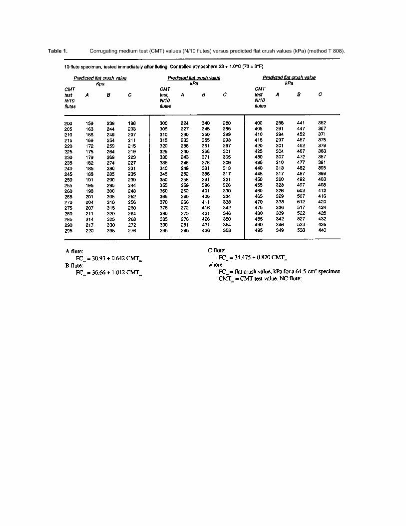
Table 1. Corrugating medium test (CMT) values (N/10 flutes) versus predicted flat crush values (kPa) (method T 808).

Table 2. Corrugating Medium Test (CMT) Values (lb/10 Flutes) Versus Predicted Flat Crush Values (lb 10 sq. in.) (method T
808).
Appendix A: Calibration
A.1 Crush tester. Calibrate the flexible beam instrument in accordance with Appendix A of TAPPI T 808
“Flat Crush Test of Corrugated Board.” Calibrate the rigid support instrument in accordance with manufacturer's
instructions.
A.2 Medium fluter
A.2.1 Fluting rolls (Horizontal roll type). Uniform meshing of fluting rolls can be checked by the use of
National Cash Register Tape - CB white NCR paper and CR green tinted NC paper C2R. A 12.7-mm (0.5-in.)-wide strip
of each type of paper is run through the fluting rolls. The pressure pattern will appear on the green tinted strip. The
pressure lines should be uniform and extend the full 12.7 mm (0.5-in.) width of the strip. If there is more impression at
the top or bottom of the rolls, they are not in the same plane. This means that the heating plate has warped, is worn
unevenly, or the bearings are worn. In any case, the fluter should go back to the manufacturer for repair.
The rolls should ride flat on the heating plate. If the drive roll is not flat on the heating plate, loosen the collar
directly above the bottom bearing housing and tap the roll lightly until it is lying flat. It may be necessary to loosen the
bottom bearing also. Make this adjustment only when the fluter is up to normal operating temperature. When the roll is
flat, tighten all bolts and set screws. Remove driven roll by taking out the center bolt and lifting the roll up by bolts
inserted in the thread holes provided. Inspect the heating plate for wear of chrome plating. If worn, a new heating plate
should be installed by the manufacturer. The roll can also be inspected for smoothness and wear on the bottom. The

spring-loaded post slide can be checked for freeness of movement and lubricated with powdered graphite, if necessary.
When the roll is replaced, powdered graphite should be added to the lubricating hole while the roll is turning. Graphite
should be added until the grooves under the roll are completely filled. The same holds true for the drive roll.
A.2.2 Spring force. The bar at the front end of the heating plate (on older model fluters) which holds the spring
in place can be removed and the spring taken out. By placing the spring upright in the compression tester and applying
force until the gage reads 100 N (22.5 lb), the length of the spring at that point can be determined.
The distance from the edge of the heating plate to the base of the slide block should correspond to the spring
length at 100 N (22.5 lb) force. Make the measurement with the driven roll in proper contact with the drive roll.
On newer model fluters the spring is under the heating plate and applies force to the roll by leverage so that the
spring exerts only 50 N (11.25 lb) of force to give 100 N (22.5 lb) on the roll. This can be checked by the method above,
or by pulling the roll back with another spring scale, or by pulling back with a spring scale at the point on the lever where
the main spring is located.
A.2.3 Temperature. The temperature of the fluting rolls should be 175 ± 8°C (350°F ± 15°F), as checked by a
pyrometer or thermocouple. Bring the rolls up to temperature with the cover in place. When the plate and rolls are up to
temperature as indicated by the amber light going out, remove the cover and take the temperature of the rolls as near the
flute tips as possible. Do this while the fluting rolls are in motion. If the temperature is not correct, adjust the thermostat
to bring the rolls to the correct temperature and make a new mark at 175°C (350°F). If the temperature cannot be
adjusted, check the heating element under the hot plate with a continuity tester. A new heating element may have to be
installed by the manufacturer.
References
1. Long, F. D., and Maltenfort, G. G., “A New Test for Corrugating Medium,” Fibre Containers 37 (12): (1952).
2. Long, F. D., and Maltenfort, G. G., “Some Aspects of the Concora Medium Test,” Tappi 39 (9): 88A (1956).
3. Maltenfort, G. G., “New Model Concora Medium Fluter,” Paperboard Packaging 46 (6): 60 (1961).
4. Long, F. D., “Automatic Concora Medium Fluter,” Paperboard Packaging 46 (7): 56 (1961).
5. Container Laboratories, “Quality Evaluation and Research Group 1961 Clinic, Preliminary Report on Effect of
New CMIT Formulas.”
6. Maltenfort, G. G., “The Effect of Sample Preparation on Concora Medium Test (CMT): A Survey,” Tappi 47
(12): 176A (1964).
7. McKee, R. C., and Whitsit, W. J., “Relationship Between Combined Board Flat Crush and Concora Flat Crush,”
Tappi 50 (9): 79A (1967).
8. Gartaganis, P. A., and Ostrowski, H. “Evaluation of the Converting Efficiency of Corrugated Combined Board -
Part I,” Tappi 52 (6): 1059 (1969).
Your comments and suggestions on this procedure are earnestly requested and should be sent to the TAPPI Director
of Quality and Standards. g