Embed Size (px)
Citation preview
STONESHIELD

2
Important Notice
This manual contains suggestions and guidelines on how to install the subject Union Corrugating products. The contents of this manual include the guidelines that were in effect at the time this publication was originally printed. In an effort to keep pace with the ever-changing code environment, Union Corrugating retains the right to change specifications and/or designs at any time without incurring any obli-gations. Application and design details are for illustrative purposes only and may not be appropriate for all environmental conditions, codes, and / or building designs. Projects should be engineered and installed to conform to applicable building codes, regulations, and accepted industry practices.
Union Corrugating assumes no liability for either incorrect installation of its prod-ucts or personal injury that may occur as a result of installing such products. Theinstallation methods demonstrated in these materials are not the only ways toinstall Union Corrugating products, but have been developed as a reference guideusing acceptable, tested and proven methods for the standard installation of Union Corrugating products. Contractors and installers should at all times use their pro-fessional judgment, and modify and tailor such methods where appropriate or nec-essary to suit each speci c installation or any applicable local building codes orordinances. Due to the fact that Union Corrugating has no control over the actualinstallation techniques used, no warranty is expressed or implied relating to instal-lation of the product. Union Corrugating’s liability with respect to Union Corrugat-ing products is limited exclusively to its standard written warranty.
Please Note: It is the responsibility of the installer to adhere to local building codes.

StoneShield Shingle Description
Parts and Accessories
Estimating
Roof Preparation
REPEL Synthetic Underlayment, Starter Strip and Rake Roof-To-Wall
Valley
Shingle Installation
Sidewall / Endwall, Headwall and Vally Cap Details
Rake / Roof-To-Wall and Hip and Ridge Details
Riglet Installation
Pipe Penetration Details
Chimney/Curb Flashing Details
Acceptable Sidelap Repair Option
4
5
6
7
8
9
10
11
12
13
14
15 - 18
19
3
Table of Contents

15 5/8”
1311/16”
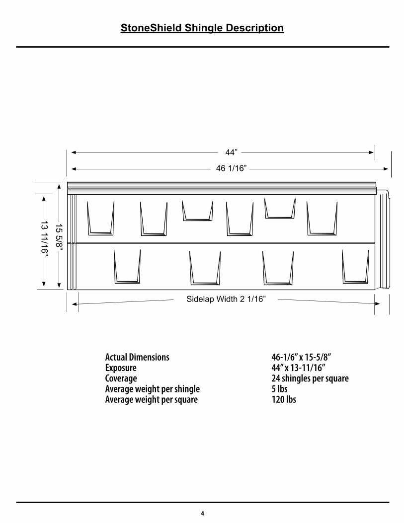
Actual Dimensions 46-1/6” x 15-5/8”Exposure 44” x 13-11/16”Coverage 24 shingles per squareAverage weight per shingle 5 lbsAverage weight per square 120 lbs
4
StoneShield Shingle Description
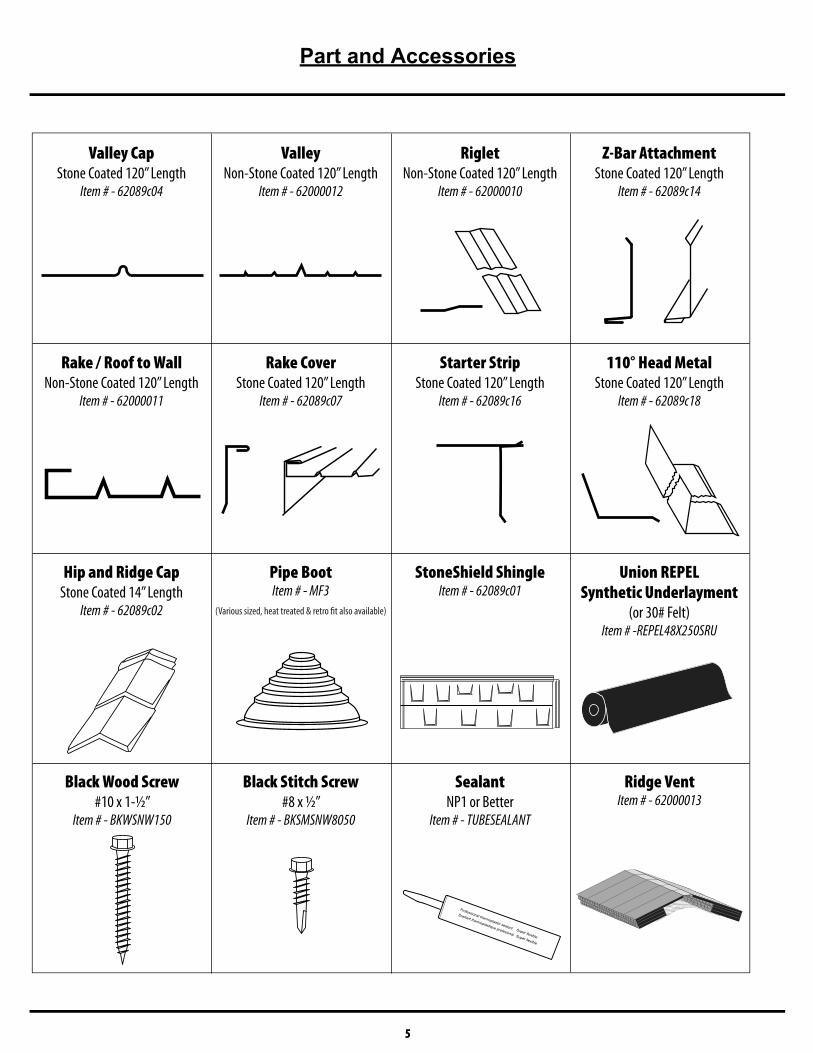
Valley CapStone Coated 120” Length
Item # - 62089c04
ValleyNon-Stone Coated 120” Length
Item # - 62000012
RigletNon-Stone Coated 120” Length
Item # - 62000010
Z-Bar AttachmentStone Coated 120” Length
Item # - 62089c14
Rake / Roof to WallNon-Stone Coated 120” Length
Item # - 62000011
Rake CoverStone Coated 120” Length
Item # - 62089c07
Starter StripStone Coated 120” Length
Item # - 62089c16
110° Head MetalStone Coated 120” Length
Item # - 62089c18
Hip and Ridge CapStone Coated 14” Length
Item # - 62089c02
Pipe BootItem # - MF3
(Various sized, heat treated & retro fit also available)
Super flexible
Professional thermoplastic sealant
Super flexible
Scellant thermoplastique profesional
StoneShield ShingleItem # - 62089c01
Union REPELSynthetic Underlayment
(or 30# Felt)Item # -REPEL48X250SRU
Black Stitch Screw#8 x ½”
Item # - BKSMSNW8050
SealantNP1 or Better
Item # - TUBESEALANT
5
Part and Accessories
Black Wood Screw#10 x 1-½”
Item # - BKWSNW150
Ridge VentItem # - 62000013
Estimating
6
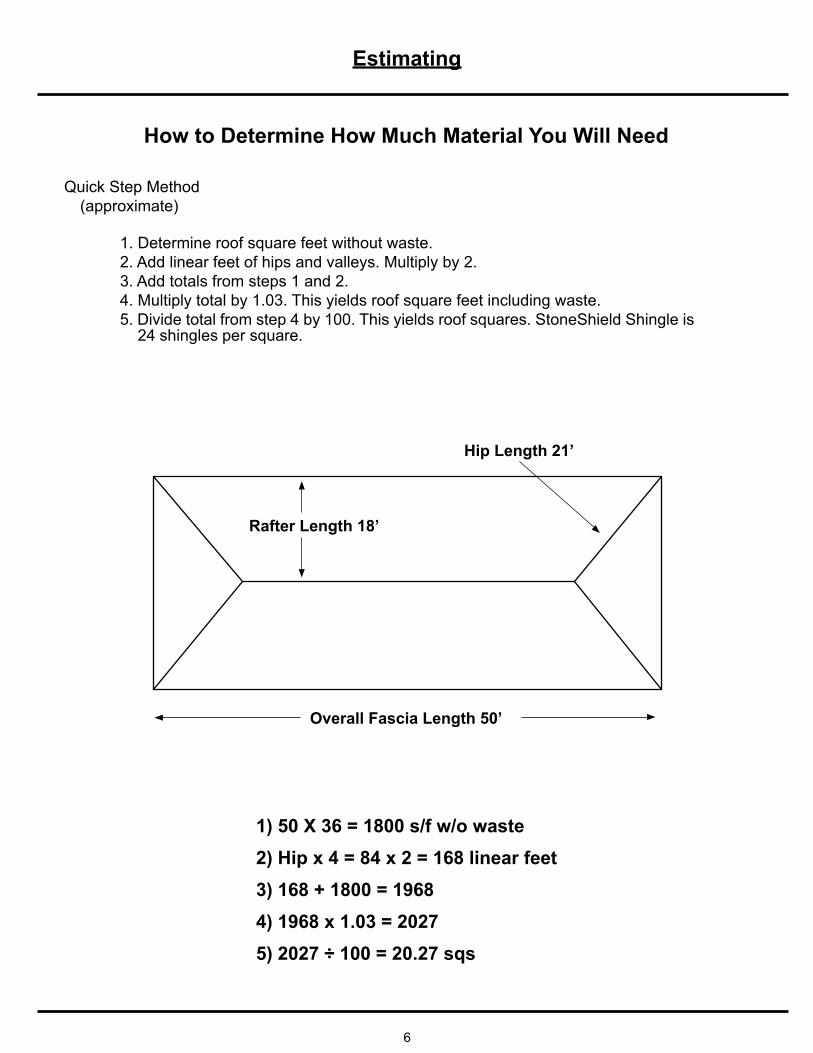
Overall Fascia Length 50’
Rafter Length 18’
Hip Length 21’
How to Determine How Much Material You Will Need
Quick Step Method(approximate)
1. Determine roof square feet without waste.2. Add linear feet of hips and valleys. Multiply by 2.3. Add totals from steps 1 and 2.4. Multiply total by 1.03. This yields roof square feet including waste.5. Divide total from step 4 by 100. This yields roof squares. StoneShield Shingle is 24 shingles per square.
1) 50 X 36 = 1800 s/f w/o waste2) Hip x 4 = 84 x 2 = 168 linear feet3) 168 + 1800 = 19684) 1968 x 1.03 = 20275) 2027 ÷ 100 = 20.27 sqs
Roof Preparation
7
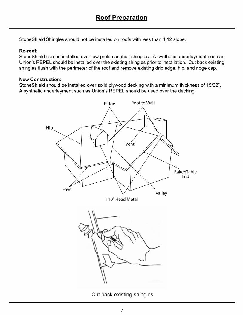
Cut back existing shingles
StoneShield Shingles should not be installed on roofs with less than 4:12 slope.
Re-roof:StoneShield can be installed over low profile asphalt shingles. A synthetic underlayment such as Union’s REPEL should be installed over the existing shingles prior to installation. Cut back existing shingles flush with the perimeter of the roof and remove existing drip edge, hip, and ridge cap.
New Construction:StoneShield should be installed over solid plywood decking with a minimum thickness of 15/32”.A synthetic underlayment such as Union’s REPEL should be used over the decking.
8
RAKE COVER
FASTEN RAKE COVER HERE
RAKE OR GABLE END
REPEL Synthetic Underlayment, Starter Strip and Rake/Roof to Wall
Starter Strip
Nail
StarterStrip
Fascia
1.
2.
3.
4.
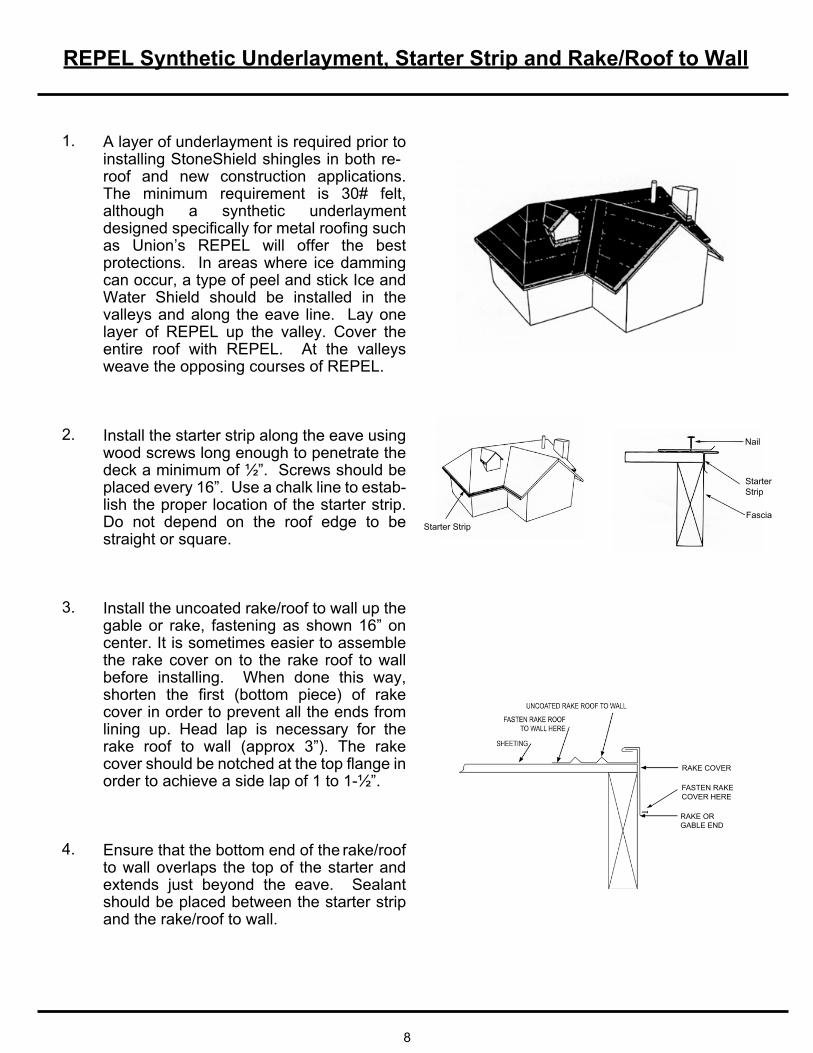
A layer of underlayment is required prior to installing StoneShield shingles in both re-roof and new construction applications. The minimum requirement is 30# felt, although a synthetic underlayment designed specifically for metal roofing such as Union’s REPEL will offer the best protections. In areas where ice damming can occur, a type of peel and stick Ice and Water Shield should be installed in the valleys and along the eave line. Lay one layer of REPEL up the valley. Cover the entire roof with REPEL. At the valleys weave the opposing courses of REPEL.
Install the starter strip along the eave using wood screws long enough to penetrate the deck a minimum of ½”. Screws should be placed every 16”. Use a chalk line to estab-lish the proper location of the starter strip. Do not depend on the roof edge to be straight or square.
Install the uncoated rake/roof to wall up the gable or rake, fastening as shown 16” on center. It is sometimes easier to assemble the rake cover on to the rake roof to wall before installing. When done this way,
cover in order to prevent all the ends from lining up. Head lap is necessary for the
order to achieve a side lap of 1 to 1-½”.
Ensure that the bottom end of the rake/roof to wall overlaps the top of the starter and
should be placed between the starter strip and the rake/roof to wall.
Valley
9
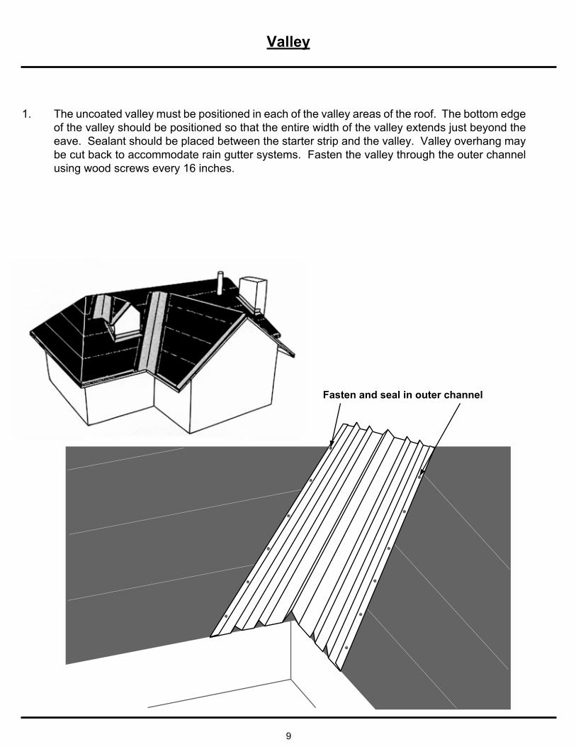
The uncoated valley must be positioned in each of the valley areas of the roof. The bottom edge of the valley should be positioned so that the entire width of the valley extends just beyond the eave. Sealant should be placed between the starter strip and the valley. Valley overhang may be cut back to accommodate rain gutter systems. Fasten the valley through the outer channel using wood screws every 16 inches.
1.
Fasten and seal in outer channel
Shingle Installationg
10
StarteStrip
Fascia
Notch
Notch
Shingle screwing pattern Underlayment
e
Installed left to right
1.
2.
3.
4.
5.
6.
7.
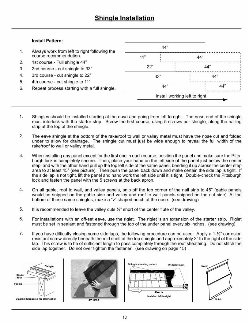
Shingles should be installed starting at the eave and going from left to right. The nose end of the shinglemust interlock with the starter strip. Screw the first course, using 5 screws per shingle, along the nailingstrip at the top of the shingle.
The eave shingle at the bottom of the rake/roof to wall or valley metal must have the nose cut and foldedunder to allow for drainage. The shingle cut must just be wide enough to reveal the full width of therake/roof to wall or valley metal.
-burgh lock is completely secure. Then, place your hand on the left side of the panel just below the center step, and with the other hand pull up the top left side of the same panel, bending it up across the center steparea to at least 45° (see picture). Then push the panel back down and make certain the side lap is tight. If
lock and fasten the panel with the 5 screws at the back apron.
On all gable, roof to wall, and valley panels, snip off the top corner of the nail strip to 45° (gable panelswould be snipped on the gable side and valley and roof to wall panels snipped on the cut side). At thebottom of these same shingles, make a “v” shaped notch at the nose. (see drawing)
It is recommended to leave the valley cuts ½” short of the center flute of the valley.
For installations with an off-set eave, use the riglet. The riglet is an extension of the starter strip. Rigletmust be set in sealant and fastened through the top of the under panel every six inches. (see drawing)
If you have difficulty closing some side laps, the following procedure can be used: Apply a 1-½” corrosion resistant screw directly beneath the mid shelf of the top shingle and approximately 3” to the right of the side lap. This screw is to be of sufficient length to pass completely through the roof sheathing. Do not stitch the side lap together. Do not over tighten the fastener. (see drawing on page 15)
45 Bend
Install Pattern:
1.
2.3.4.5.6.
Always work from left to right following thecourse recommendation.1st course - Full shingle 44”2nd course - cut shingle to 33”3rd course - cut shingle to 22”4th course - cut shingle to 11”Repeat process starting with a full shingle.
44”
44”
44”
44”
44”
44”
11”
22”
33”
Install working left to right
Sidewall/Endwall, Headwall and Valley Cap Details
11
Shingle
Z-Bar AttachmentRake/Roof-To-Wall
110° Head Metal
Builder Installed Z-Bar
Rake/Roof-to-Wall 110° Head MetalRake/Roof-to-Wall 110° Head Metal
Valley Cap
FasciaScrewChipped and Caulked
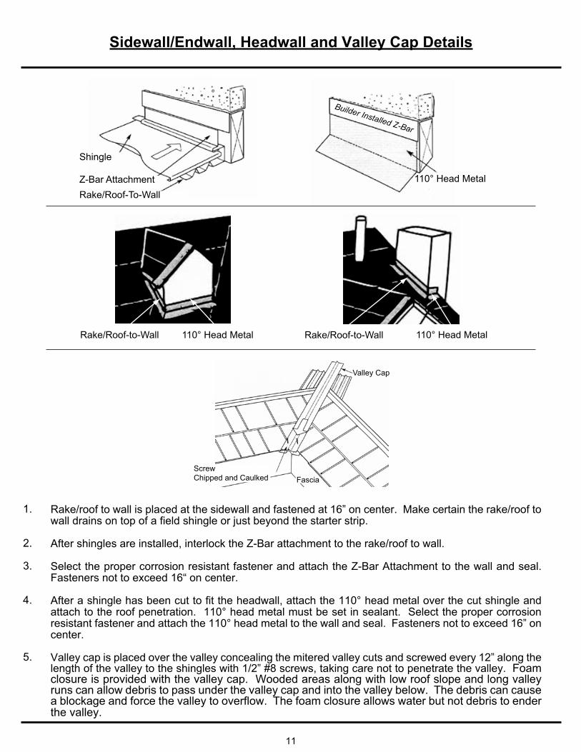
Rake/roof to wall is placed at the sidewall and fastened at 16” on center. Make certain the rake/roof to wall drains on top of a field shingle or just beyond the starter strip.
After shingles are installed, interlock the Z-Bar attachment to the rake/roof to wall.
Select the proper corrosion resistant fastener and attach the Z-Bar Attachment to the wall and seal. Fasteners not to exceed 16“ on center.
After a shingle has been cut to fit the headwall, attach the 110° head metal over the cut shingle and attach to the roof penetration. 110° head metal must be set in sealant. Select the proper corrosion resistant fastener and attach the 110° head metal to the wall and seal. Fasteners not to exceed 16” on center.
Valley cap is placed over the valley concealing the mitered valley cuts and screwed every 12” along thelength of the valley to the shingles with 1/2” #8 screws, taking care not to penetrate the valley. Foamclosure is provided with the valley cap. Wooded areas along with low roof slope and long valley runs can allow debris to pass under the valley cap and into the valley below. The debris can cause a blockage and force the valley to overflow. The foam closure allows water but not debris to ender the valley.
1.
2.
3.
4.
5.
Rake Roof to Wall and Hip and Ridge Details
12
Hip Cap
Mitre Cut
Screws - Seal and Chip
Ridge Cap
ScrewsSeal and Chip
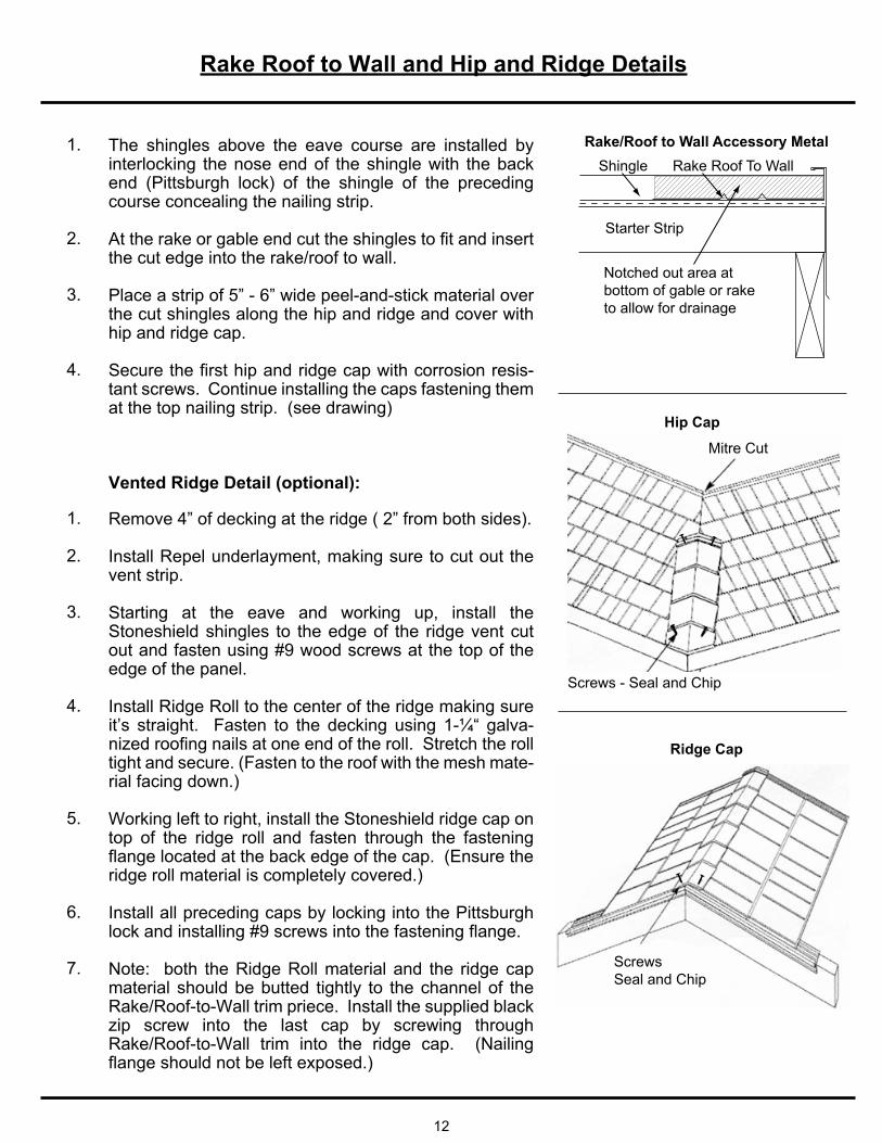
The shingles above the eave course are installed by interlocking the nose end of the shingle with the back end (Pittsburgh lock) of the shingle of the preceding course concealing the nailing strip.
the cut edge into the rake/roof to wall.
Place a strip of 5” - 6” wide peel-and-stick material over the cut shingles along the hip and ridge and cover with hip and ridge cap.
Secure the first hip and ridge cap with corrosion resis-tant screws. Continue installing the caps fastening them at the top nailing strip. (see drawing)
1.
2.
3.
4.
Rake/Roof to Wall Accessory MetalShingle Rake Roof To Wall
Starter Strip
Notched out area at bottom of gable or rake to allow for drainage
Remove 4” of decking at the ridge ( 2” from both sides).
Install Repel underlayment, making sure to cut out the vent strip.
Starting at the eave and working up, install the Stoneshield shingles to the edge of the ridge vent cut out and fasten using #9 wood screws at the top of the edge of the panel.
Install Ridge Roll to the center of the ridge making sure it’s straight. Fasten to the decking using 1-¼“ galva-nized roofing nails at one end of the roll. Stretch the roll tight and secure. (Fasten to the roof with the mesh mate-rial facing down.)
Working left to right, install the Stoneshield ridge cap on top of the ridge roll and fasten through the fastening flange located at the back edge of the cap. (Ensure the ridge roll material is completely covered.)
Install all preceding caps by locking into the Pittsburgh lock and installing #9 screws into the fastening flange.
Note: both the Ridge Roll material and the ridge cap material should be butted tightly to the channel of the Rake/Roof-to-Wall trim priece. Install the supplied black zip screw into the last cap by screwing through Rake/Roof-to-Wall trim into the ridge cap. (Nailing flange should not be left exposed.)
1.
2.
3.
4.
5.
6.
7.
Vented Ridge Detail (optional):
Riglet Installation
13
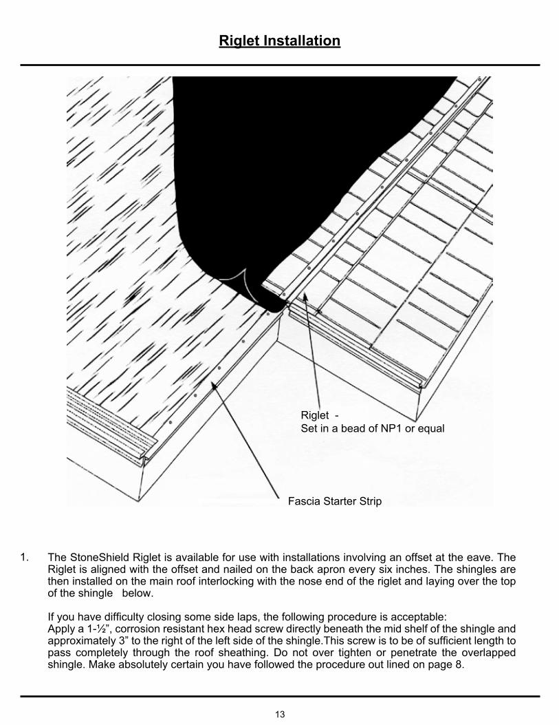
Riglet -Set in a bead of NP1 or equal
Fascia Starter Strip
The StoneShield Riglet is available for use with installations involving an offset at the eave. The Riglet is aligned with the offset and nailed on the back apron every six inches. The shingles are then installed on the main roof interlocking with the nose end of the riglet and laying over the top of the shingle below.
pass completely through the roof sheathing. Do not over tighten or penetrate the overlapped shingle. Make absolutely certain you have followed the procedure out lined on page 8.
1.
Pipe Penetration Details
14
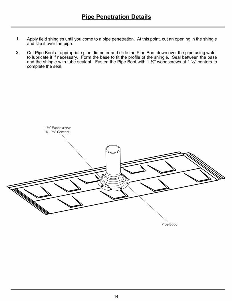
Apply field shingles until you come to a pipe penetration. At this point, cut an opening in the shingle and slip it over the pipe.
Cut Pipe Boot at appropriate pipe diameter and slide the Pipe Boot down over the pipe using water to lubricate it if necessary. Form the base to fit the profile of the shingle. Seal between the base and the shingle with tube sealant. Fasten the Pipe Boot with 1-½” woodscrews at 1-½” centers to complete the seal.
1.
2.
1-½" Woodscrew@ 1-½" Centers
Pipe Boot
Chimney / Curb Flashing Details
15
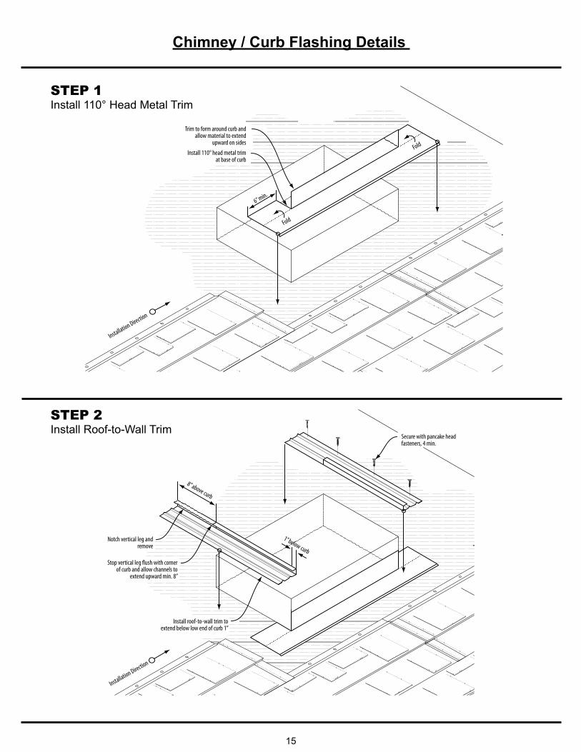
STEP 1Install 110° Head Metal Trim
STEP 2Install Roof-to-Wall Trim
Trim to form around curb and allow material to extend
upward on sides
Install 110° head metal trim at base of curb
Installation Direction
6” min.
Fold
Fold
Notch vertical leg and remove
Installation Direction
Stop vertical leg flush with corner of curb and allow channels to
extend upward min. 8”
Install roof-to-wall trim to extend below low end of curb 1”
Secure with pancake head fasteners, 4 min.
8” above curb
1” below curb
Chimney / Curb Flashing Details
16
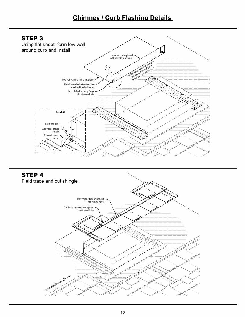
STEP 3Using flat sheet, form low wall around curb and install
Set flashing and field trace against
curb and roof-to-wall trim to
determine profile prior to cut
Low Wall Flashing (using flat sheet)
Fasten vertical leg to curb with pancake head screws
Allow low wall edge to extend into channel and trim back excess
Form tab flush with top flange of roof-to-wall trim
Notch and fold
Apply bead of tube sealant
Trim and remove excess
Detail A1
A1
STEP 4Field trace and cut shingle
Trace shingle to fit around curb and remove excess
Installation Direction
Cut slit each side to allow lap over roof-to-wall trim
Chimney / Curb Flashing Details
17
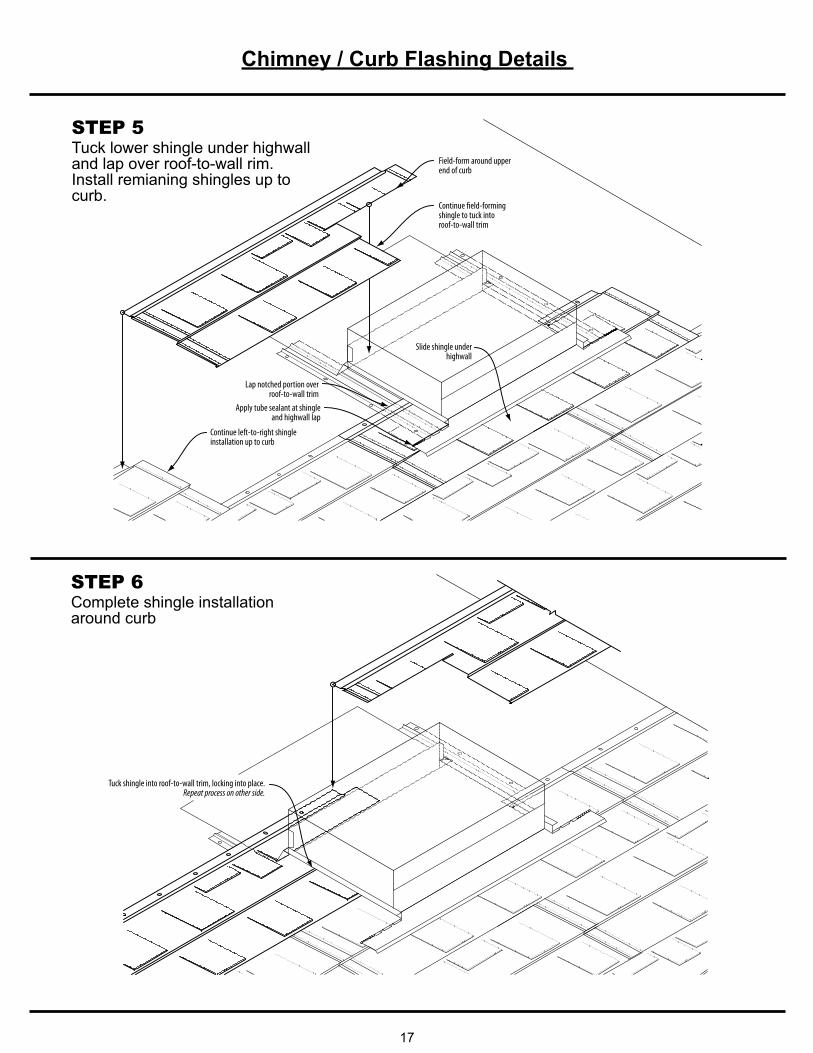
STEP 5Tuck lower shingle under highwall and lap over roof-to-wall rim.Install remianing shingles up to curb.
Lap notched portion over roof-to-wall trim
Field-form around upper end of curb
Apply tube sealant at shingle and highwall lap
Continue left-to-right shingle installation up to curb
Continue field-forming shingle to tuck into roof-to-wall trim
Slide shingle under highwall
STEP 6Complete shingle installation around curb
Tuck shingle into roof-to-wall trim, locking into place.Repeat process on other side.
Chimney / Curb Flashing Details
18
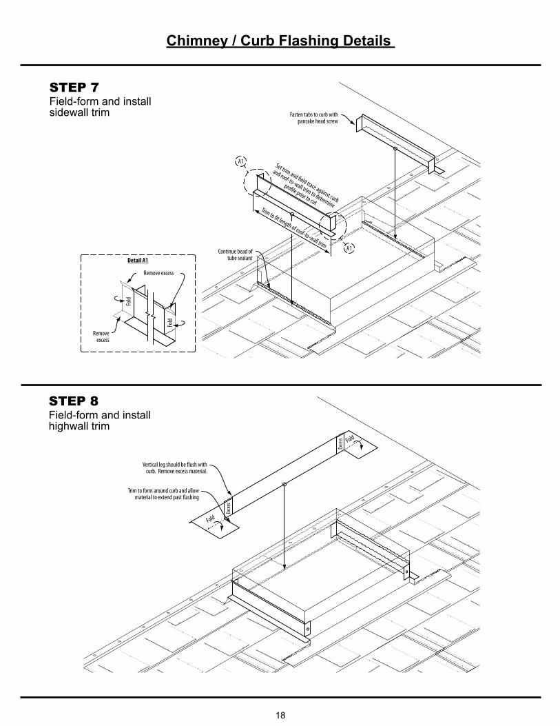
STEP 7Field-form and install sidewall trim
Remove excess
Detail A1
Fasten tabs to curb with pancake head screw
Set trim and field trace against curb
and roof-to-wall trim to determine
profile prior to cut
Continue bead of tube sealant
Removeexcess
Trim to fit length of roof-to-wall trim
A1
A1
Fold
Fold
STEP 8Field-form and install highwall trim
Vertical leg should be flush with curb. Remove excess material.
Exce
ss
Fold
Exce
ss Fold
Trim to form around curb and allow material to extend past flashing
Acceptable Sidelap Repair Option
19
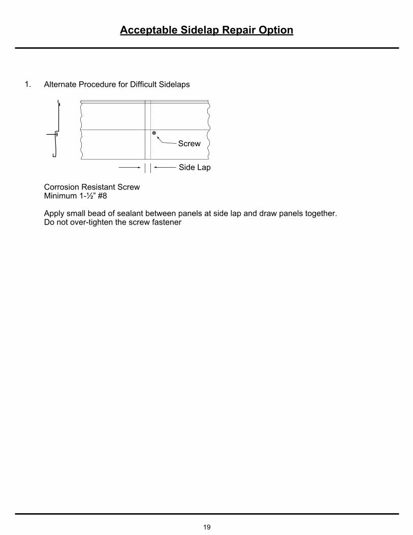
Side Lap
Screw
Alternate Procedure for Difficult Sidelaps
Corrosion Resistant ScrewMinimum 1-½” #8
Apply small bead of sealant between panels at side lap and draw panels together.Do not over-tighten the screw fastener
1.


Copyright © 2012 by Union Corrugating Company. All rights reserved. No part of this document may be reproduced or distributed in any form whatsoever without prior written authorization.
SPENCER STEEL SUPPLYSPENCER, NC
NORTHEAST DIVISIONSCRANTON, PA
GREAT PLAINS METALSOKLAHOMA CITY, OK
DAYTON METALSDAYTON, OH
VICKSBURG METAL PRODUCTSVICKSBURG, MS
UNICO METAL PRODUCTSOCALA, FL
TIFTON STEEL PRODUCTSTIFTON, GA
ORANGE STEEL ROOFINGORANGE, VA
ANDERSON STEEL SUPPLYANDERSON, SC
PO Box 229 • Fayetteville, NC 28302 • 888-MTL-ROOF (685-7663) • Fax: 800-586-2498


![07 Belts for Corrugating & Carton Box Makin 0419 - Nitta · [ RT-22E70-2] Belts for Corrugating & Carton Box Making RT-22E70-2 NRT-100 RT-300 NRT-500 High COF High conveyance capacity](https://img.pdfslide.us/doc/110x75/60b60651cfb5682e510b4918/07-belts-for-corrugating-carton-box-makin-0419-rt-22e70-2-belts-for-corrugating.jpg)