Embed Size (px)
Citation preview
FLAP VALVESTBS SOEST bvbbR
SPECIALISED IN WATER MANAGEMENT PRODUCTS
Modifications reserved.2.0
AN INTRODUCTION TO FLAP VALVES 2.1
HDPE FLAP VALVE PTK-G 2.7
HDPE FLAP VALVE PTK-A 2.12
HDPE FLAP VALVE PWK-F 2.17
HDPE FLAP VALVE PTK-P 2.21
HDPE FLAP VALVE PTK-BS 2.22
HDPE FLAP VALVE PTK-F 2.23
HDPE LIFTABLE FLAP VALVE POTK 2.24
INSTALLATION INSTRUCTIONS 2.25
AN INTRODUCTIONTO FLAP VALVES
TBS SOEST bvbbR
SPECIALISED IN WATER MANAGEMENT PRODUCTS
INTRODUCTION
Good flap valves work in the background withoutbeing noticed. Only at times of high water or floo-ding do people realise the importance of suchnon-return valves. On these critical occasions youmust be able to rely on the flap valves you haveinstalled.
Basically, flap valves allow for the removal ofexcess water and prevent back flow.
This function has to be performed over long peri-ods. At the same time the valves must not be sen-sitive to rust, corrosion or clogging.
TRADITIONAL DESIGN
Traditional metal flap valves suffer from a num-ber of problems.
They are made of cast iron, which is heavy. Thisresults in high head losses and all manner of rub-bish can accumulate behind the door before itopens to discharge the water build-up. This canresult in complete blockage of the valve. Thusregular checking, maintenance and cleaning isessential.
Methods of reducing the high opening pressuresrequired for metal valves are hollow doors filledwith oil or counter weights added above thevalve. This in turn makes the valve more complexto mount and takes up more space in the con-struction.
Corrosion is also a big problem, especially whenthe valves are exposed to seawater. Coatings arerequired to provide protection.
HDPEOur HDPE flap valves provide the customer withmuch improved characteristics:
- no corrosion- good chemical resistance against acids,
salts and alkalis in aqueous solutions, many solvents, oils, etc
- high UV protection by addition of carbon to the material to stabilise for outside use
- use between -50ºC and +70ºC (constructive values)
- low density and lightweight- a material as easy to machine as wood- dimensional stability
- no rotting- no material fatigue- impact resistance- high flexibility- economic design and material
These characteristics result in the followingcustomer benefits:
- long service life because the material does not corrode
- no coatings needed in aggressive environ-ments
- very low opening pressures compared to metal flap valves
- low head losses
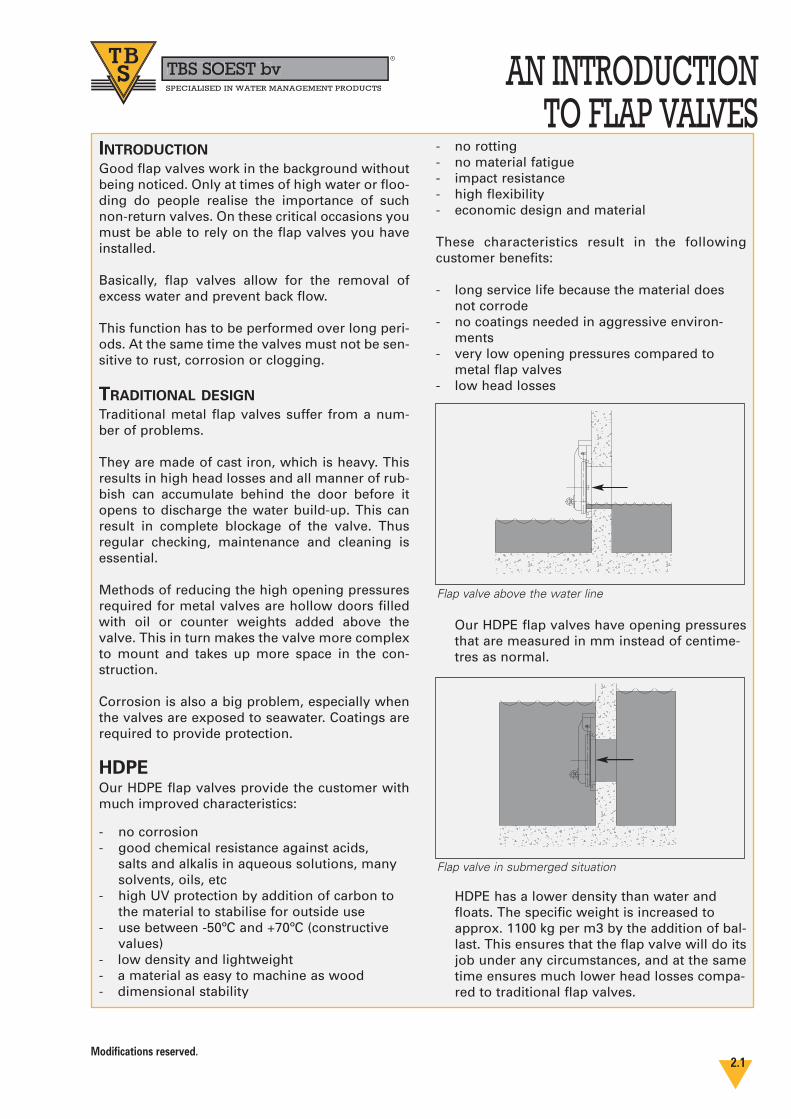
Our HDPE flap valves have opening pressuresthat are measured in mm instead of centime-tres as normal.
HDPE has a lower density than water and floats. The specific weight is increased to approx. 1100 kg per m3 by the addition of bal-last. This ensures that the flap valve will do itsjob under any circumstances, and at the sametime ensures much lower head losses compa-red to traditional flap valves.
Modifications reserved.2.1
Flap valve above the water line
Flap valve in submerged situation
AN INTRODUCTIONTO FLAP VALVES
TBS SOEST bvbbR
SPECIALISED IN WATER MANAGEMENT PRODUCTS
When the valve is completely submerged, the differential opening pressure is not more than 10 mm water column!
- minimal maintenance. As the material remains smooth, it is much more difficult for dirt to stick to the surface.
- lightweight construction - easy to install and handle.
- HDPE is a solid material. Possible damage to the outside will not result in corrosion inside.
- flexibility in design. The unique CAD/CAM production system enables TBS SOEST bv to make special designs and provide tailor madesolutions with short project lead times. Products can be adapted to a specific (opening) pressure or installation situation.
More than 50 % of the products made are special tailor made designs.
TBS flap valves are made for both gravitationalflow / free flow (PTK) and pumping stations(PWK) and from 150 mm up to 2000 mm diameterand even larger.
SELECTION CONSIDERATIONS
We provide a checklist that takes numerous fac-tors into account to help establish what exactly isrequired. There are different flap valves for vari-ous applications:- permanently submerged or flood
prevention / emergency- gravitational flow or pressure pipes- different mounting situations, such as wall
mounting, flange, PVC and concrete tubes
We can provide the best solution for every situation.
To determine which product is suitable for whichsituation the following have to be taken into con-sideration:
1) dimensions of the opening
2) application
3) type of flow: gravity or pressure pipe?
4) maximum water pressure on the front in metres water column? Is it permanent or temporary?
5) what is the installation situation?
APPLICATION
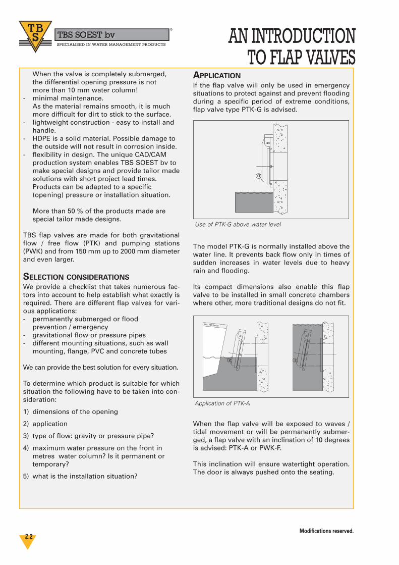
If the flap valve will only be used in emergencysituations to protect against and prevent floodingduring a specific period of extreme conditions,flap valve type PTK-G is advised.
The model PTK-G is normally installed above thewater line. It prevents back flow only in times ofsudden increases in water levels due to heavyrain and flooding.
Its compact dimensions also enable this flapvalve to be installed in small concrete chamberswhere other, more traditional designs do not fit.
When the flap valve will be exposed to waves /tidal movement or will be permanently submer-ged, a flap valve with an inclination of 10 degreesis advised: PTK-A or PWK-F.
This inclination will ensure watertight operation.The door is always pushed onto the seating.
Modifications reserved.2.2
Use of PTK-G above water level
M.S. TBS Soest
Application of PTK-A
AN INTRODUCTIONTO FLAP VALVES
TBS SOEST bvbbR
SPECIALISED IN WATER MANAGEMENT PRODUCTS
GRAVITATION VERSUS PRESSURE PIPE
SITUATIONS
The flow situation is also important for determi-ning the type of flap valve needed.
A flap valve of type PTK is used for free flow.Flow is achieved by gravity at low velocities.
When the flap valve is situated at the end of apressure pipeline / pumping station, the flapvalve type PTK cannot be used; you will require aflap valve type PWK.
Using a standard valve in this type of pumpingsituation will result in serious damage to the sealand hinges.
AIR VENT FUNCTION
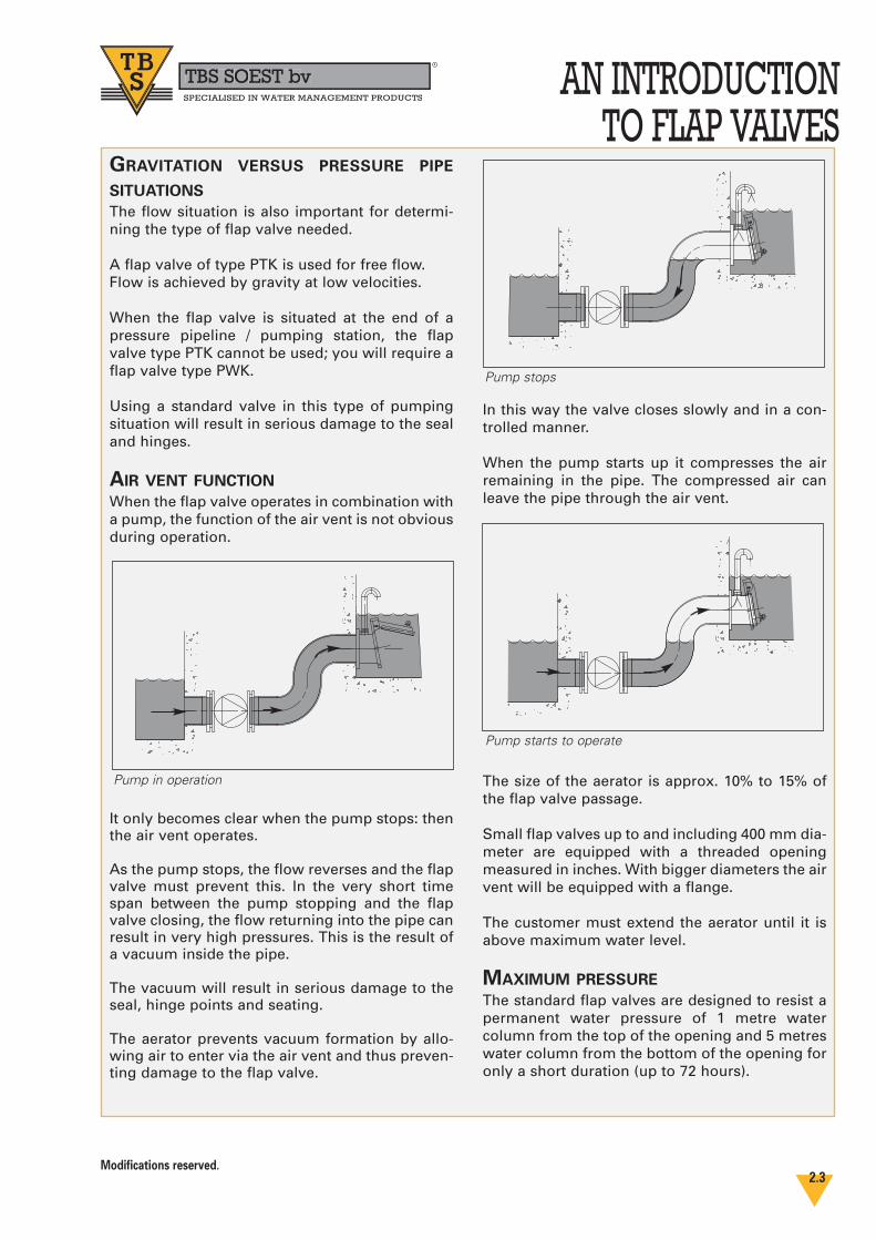
When the flap valve operates in combination witha pump, the function of the air vent is not obviousduring operation.
It only becomes clear when the pump stops: thenthe air vent operates.
As the pump stops, the flow reverses and the flapvalve must prevent this. In the very short timespan between the pump stopping and the flapvalve closing, the flow returning into the pipe canresult in very high pressures. This is the result ofa vacuum inside the pipe.
The vacuum will result in serious damage to theseal, hinge points and seating.
The aerator prevents vacuum formation by allo-wing air to enter via the air vent and thus preven-ting damage to the flap valve.
In this way the valve closes slowly and in a con-trolled manner.
When the pump starts up it compresses the airremaining in the pipe. The compressed air canleave the pipe through the air vent.
The size of the aerator is approx. 10% to 15% ofthe flap valve passage.
Small flap valves up to and including 400 mm dia-meter are equipped with a threaded openingmeasured in inches. With bigger diameters the airvent will be equipped with a flange.
The customer must extend the aerator until it isabove maximum water level.
MAXIMUM PRESSURE
The standard flap valves are designed to resist apermanent water pressure of 1 metre watercolumn from the top of the opening and 5 metreswater column from the bottom of the opening foronly a short duration (up to 72 hours).
Modifications reserved.2.3
Pump in operation
Pump stops
Pump starts to operate

The same pressure ratings apply to all TBS flapvalves:1 5 metres water column from bottom of invert
for short duration (up to 72 hours)2 1 metre water column from top of opening
permanently.If the pressure differs from the above situations -especially if it is higher -, it is always advisable toinform TBS. Then the flap valve can be adapted tothe required pressure.
INSTALLATION SITUATION
WALL MOUNTING
As most outlets are designed in concrete structu-res, the most common method of installation is“wall mounting”. The flap valve type PTK–A (withangle of 10 degrees) or PTK-G (vertical) can beinstalled.
A neoprene gasket is included in the delivery toensure a watertight connection between the walland the frame plate.
FLANGEThe flap valve can also be mounted on a counterflange. Our standard flange is in accordance withDIN EN 1092-2 standard PN10. Other flanges (BS,ASTM, DIN PN 16) can be supplied on request.
The connection F for flange will always be usedfor the PWK flap valve that requires a connectionresistant to tensile stresses.
Special flange packing and bolts are not suppliedas standard.
PVC TUBE
The P model can be connected to a PVC / HDPEtube with a socket. As you can see in the table onpage 21, the outside diameter of the connection isequal to the outside diameter of the PVC tube. Sothe flap valve with P connection can be easilymounted to a PVC tube with a socket.
AN INTRODUCTIONTO FLAP VALVES
TBS SOEST bvbbR
SPECIALISED IN WATER MANAGEMENT PRODUCTS
Modifications reserved.2.4
Top of opening
Bottom invert
PTK-G wall mounting
PTK-A wall mounting
PTK-F with flange
2
1
AN INTRODUCTIONTO FLAP VALVES
TBS SOEST bvbbR
SPECIALISED IN WATER MANAGEMENT PRODUCTS
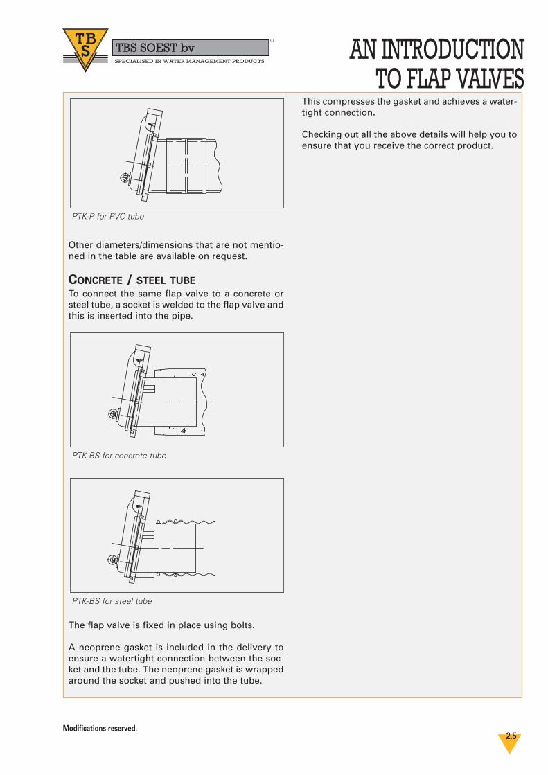
Other diameters/dimensions that are not mentio-ned in the table are available on request.
CONCRETE / STEEL TUBE
To connect the same flap valve to a concrete orsteel tube, a socket is welded to the flap valve andthis is inserted into the pipe.
The flap valve is fixed in place using bolts.
A neoprene gasket is included in the delivery toensure a watertight connection between the soc-ket and the tube. The neoprene gasket is wrappedaround the socket and pushed into the tube.
This compresses the gasket and achieves a water-tight connection.
Checking out all the above details will help you toensure that you receive the correct product.
Modifications reserved.2.5
PTK-P for PVC tube
PTK-BS for concrete tube
PTK-BS for steel tube
TBS SOEST bvbbR
SPECIALISED IN WATER MANAGEMENT PRODUCTS
Modifications reserved.
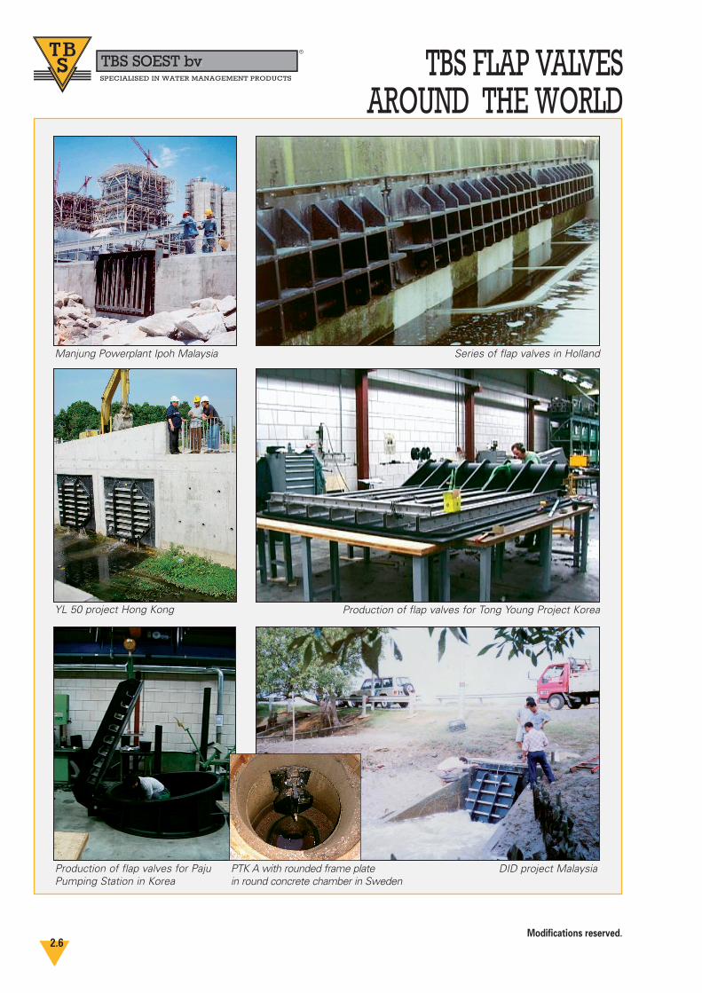
TBS FLAP VALVESAROUND THE WORLD
YL 50 project Hong Kong
Series of flap valves in HollandManjung Powerplant Ipoh Malaysia
DID project MalaysiaProduction of flap valves for PajuPumping Station in Korea
Production of flap valves for Tong Young Project Korea
PTK A with rounded frame plate in round concrete chamber in Sweden
2.6
Modifications reserved.2.7
HDPE FLAP VALVETBS SOEST bvbbR
SPECIALISED IN WATER MANAGEMENT PRODUCTS
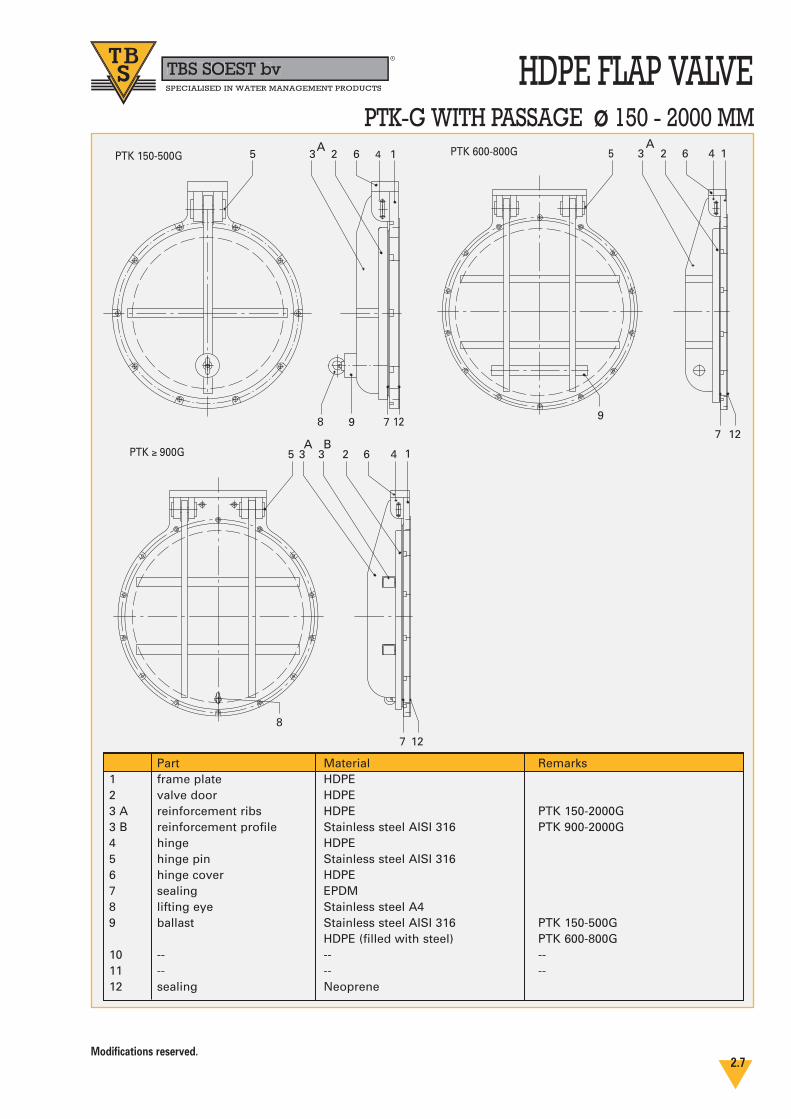
PTK-G WITH PASSAGE ø 150 - 2000 MM
798
3 2 6 4 15
12
PTK 150-500G
7
3 2 6 4 15
12
PTK 600-800G
9
7
3 2 6 4 15
12
PTK ≥ 900G
8
3
Part1 frame plate2 valve door3 A reinforcement ribs3 B reinforcement profile4 hinge5 hinge pin6 hinge cover7 sealing8 lifting eye9 ballast
10 --11 --12 sealing
Material HDPEHDPEHDPEStainless steel AISI 316HDPEStainless steel AISI 316HDPEEPDMStainless steel A4Stainless steel AISI 316HDPE (filled with steel)----Neoprene
Remarks
PTK 150-2000GPTK 900-2000G
PTK 150-500GPTK 600-800G----
A B
A A
TBS SOEST bvbbR
SPECIALISED IN WATER MANAGEMENT PRODUCTS
Modifications reserved.2.8
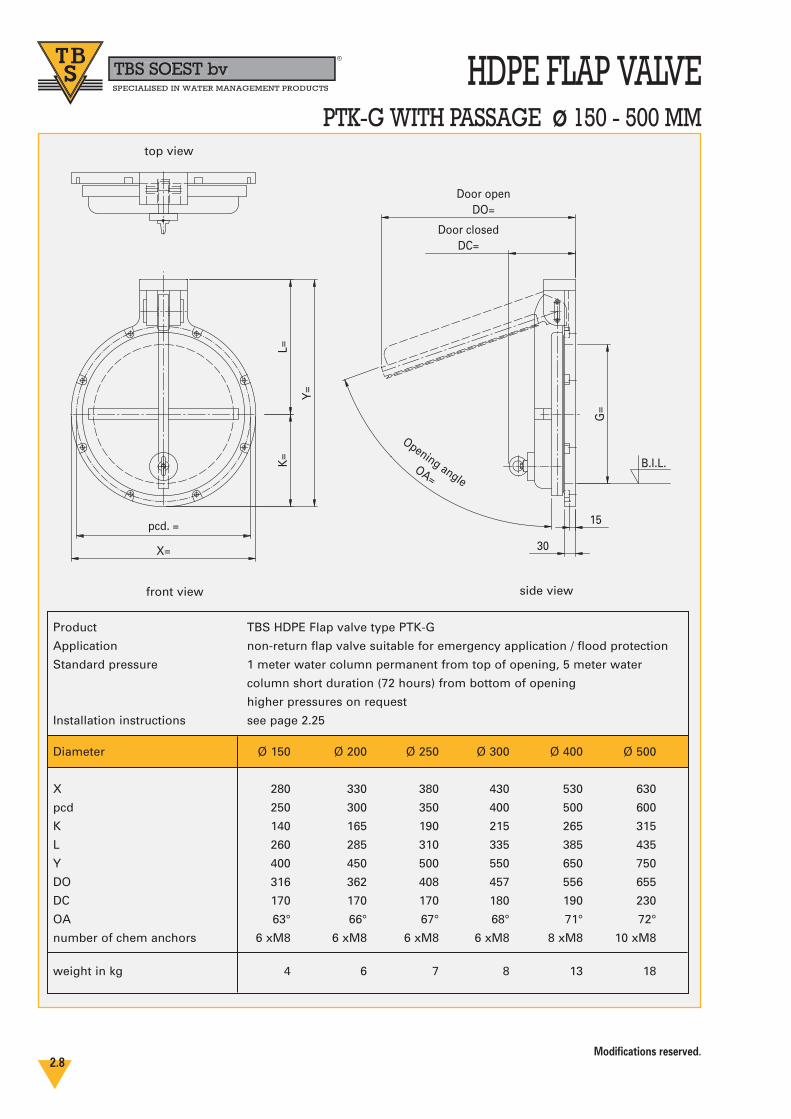
HDPE FLAP VALVEPTK-G WITH PASSAGE ø 150 - 500 MM
X=
K=
pcd. =
Y=
G=
15
30
Door closedDC=
L=
Door openDO=
Opening angleOA=
B.I.L.
top view
front view side view
Product TBS HDPE Flap valve type PTK-G
Application non-return flap valve suitable for emergency application / flood protection
Standard pressure 1 meter water column permanent from top of opening, 5 meter water
column short duration (72 hours) from bottom of opening
higher pressures on request
Installation instructions see page 2.25
Diameter Ø 150 Ø 200 Ø 250 Ø 300 Ø 400 Ø 500
X 280 330 380 430 530 630
pcd 250 300 350 400 500 600
K 140 165 190 215 265 315
L 260 285 310 335 385 435
Y 400 450 500 550 650 750
DO 316 362 408 457 556 655
DC 170 170 170 180 190 230
OA 63° 66° 67° 68° 71° 72°
number of chem anchors 6 xM8 6 xM8 6 xM8 6 xM8 8 xM8 10 xM8
weight in kg 4 6 7 8 13 18
Modifications reserved.2.9
HDPE FLAP VALVETBS SOEST bvbbR
SPECIALISED IN WATER MANAGEMENT PRODUCTS
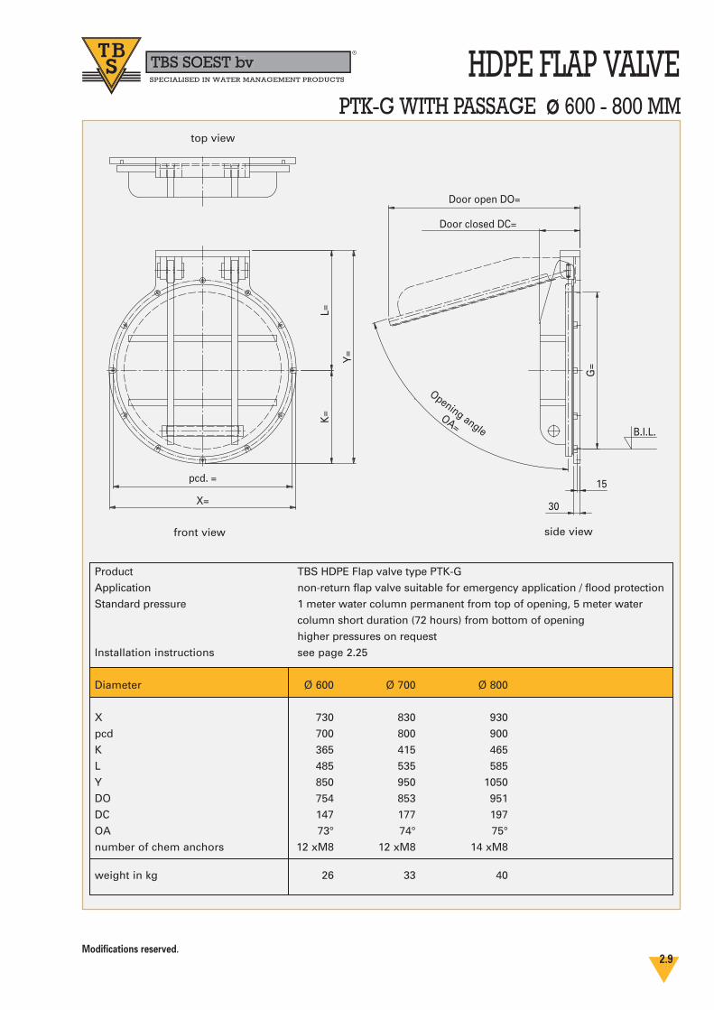
PTK-G WITH PASSAGE ø 600 - 800 MM
X=
K=
Door closed DC=
pcd. =
Y=
G=
L=
15
30
Door open DO=
Opening angleOA=
B.I.L.
top view
side viewfront view
Product TBS HDPE Flap valve type PTK-G
Application non-return flap valve suitable for emergency application / flood protection
Standard pressure 1 meter water column permanent from top of opening, 5 meter water
column short duration (72 hours) from bottom of opening
higher pressures on request
Installation instructions see page 2.25
Diameter Ø 600 Ø 700 Ø 800
X 730 830 930
pcd 700 800 900
K 365 415 465
L 485 535 585
Y 850 950 1050
DO 754 853 951
DC 147 177 197
OA 73° 74° 75°
number of chem anchors 12 xM8 12 xM8 14 xM8
weight in kg 26 33 40

TBS SOEST bvbbR
SPECIALISED IN WATER MANAGEMENT PRODUCTS
Modifications reserved.2.10
HDPE FLAP VALVEPTK-G WITH PASSAGE ø 900 - 2000 MM
X=
K=
pcd. =
Y=
G=
L=
Door closed DC=
30
Door open DO=
Opening angle
OA=
B.I.L.
side view
top view
front view
Product TBS HDPE Flap valve type PTK-G
Application non-return flap valve suitable for emergency application / flood protection
Standard pressure 1 meter water column permanent from top of opening, 5 meter water column
short duration (72 hours) from bottom of opening
higher pressures on request
bigger dimensions upon request
Installation instructions see page 2.25
Diameter Ø 900 Ø 1000 Ø 1200 Ø 1500 Ø 1600 Ø 1800 Ø 2000
X 1030 1130 1400 1700 1800 2000 2200
pcd 1000 1100 1350 1650 1750 1950 2150
K 515 565 700 850 900 1000 1100
L 635 685 825 975 1025 1125 1225
Y 1150 1250 1525 1825 1925 2125 2325
DO 1050 1149 1413 1703 1784 1977 2180
DC 227 227 227 247 247 307 307
OA 75° 76° 76° 76° 76° 76° 76°
number of chem anchors 18 xM8 20 xM8 24 xM8 28 xM10 28 xM10 32 xM10 36 xM10
weight in kg 51 58 73 128 155 225 275
Modifications reserved.2.11
HDPE FLAP VALVETBS SOEST bvbbR
SPECIALISED IN WATER MANAGEMENT PRODUCTS
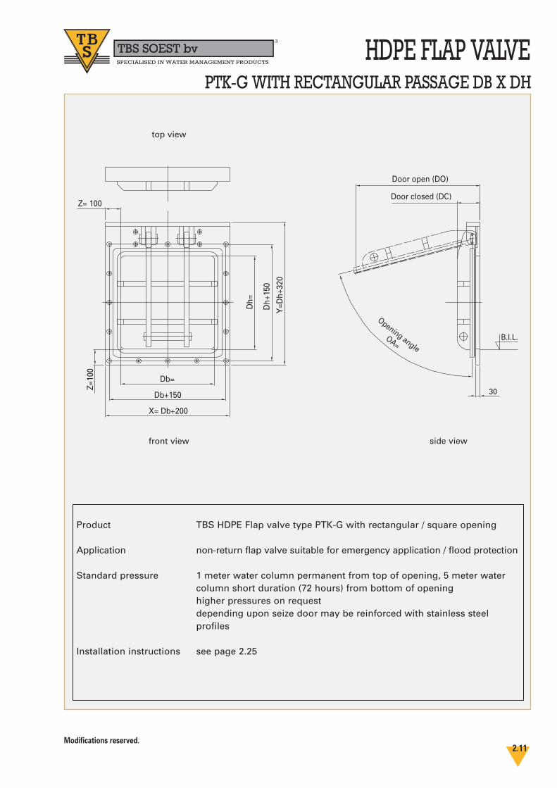
PTK-G WITH RECTANGULAR PASSAGE DB X DH
Z= 100
Db=
Db+150
X= Db+200
Z=10
0
Dh=
Dh+
150
Y=D
h+32
0
Door open (DO)
Door closed (DC)
B.I.L.
30
Opening angleOA=
side view
top view
front view
Product TBS HDPE Flap valve type PTK-G with rectangular / square opening
Application non-return flap valve suitable for emergency application / flood protection
Standard pressure 1 meter water column permanent from top of opening, 5 meter water column short duration (72 hours) from bottom of openinghigher pressures on requestdepending upon seize door may be reinforced with stainless steel profiles
Installation instructions see page 2.25
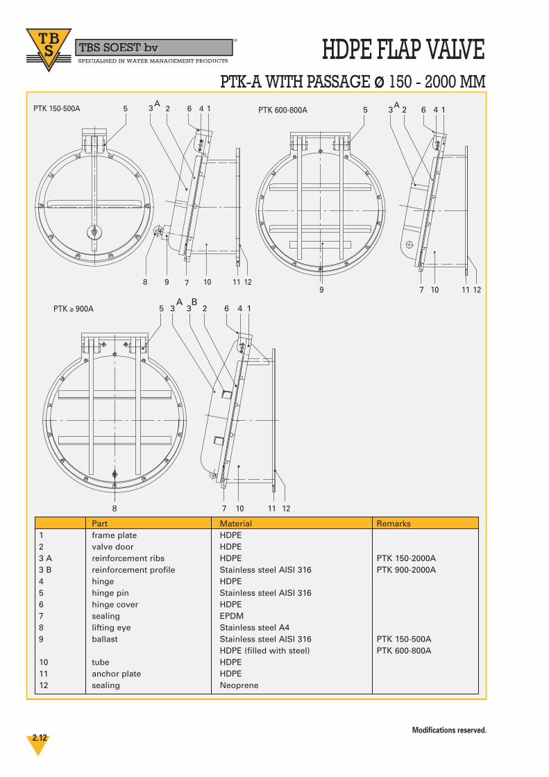
HDPE FLAP VALVEPTK-A WITH PASSAGE ø 150 - 2000 MM
798
3 2 6 4 15
10 11 12
PTK 150-500A
79
3 2 6 4 15
10 11 12
PTK 600-800A
78
3 2 6 4 15
10 11 12
PTK ≥ 900A 3
Part Material Remarks1 frame plate HDPE2 valve door HDPE3 A reinforcement ribs HDPE PTK 150-2000A3 B reinforcement profile Stainless steel AISI 316 PTK 900-2000A4 hinge HDPE5 hinge pin Stainless steel AISI 3166 hinge cover HDPE7 sealing EPDM8 lifting eye Stainless steel A49 ballast Stainless steel AISI 316 PTK 150-500A
HDPE (filled with steel) PTK 600-800A10 tube HDPE11 anchor plate HDPE12 sealing Neoprene
A B
A A
Modifications reserved.2.12
TBS SOEST bvbbR
SPECIALISED IN WATER MANAGEMENT PRODUCTS
TBS SOEST bvbbR
SPECIALISED IN WATER MANAGEMENT PRODUCTS
Modifications reserved.2.13
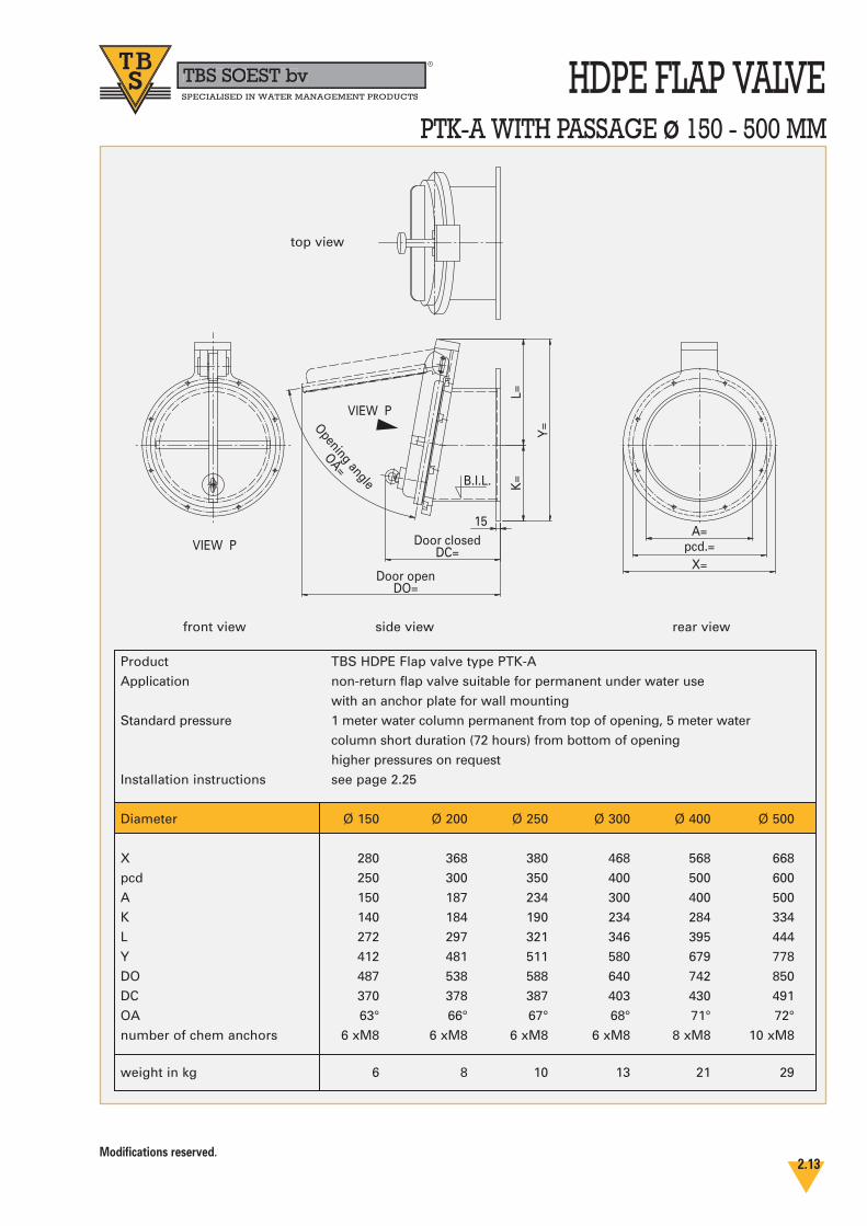
HDPE FLAP VALVEPTK-A WITH PASSAGE ø 150 - 500 MM
pcd.=X=
A=15
Door closedDC=
L=K
=
Y=
Door openDO=
B.I.L.
Opening angle
OA=VIEW P
VIEW P
side view
top view
front view rear view
Product TBS HDPE Flap valve type PTK-A
Application non-return flap valve suitable for permanent under water use
with an anchor plate for wall mounting
Standard pressure 1 meter water column permanent from top of opening, 5 meter water
column short duration (72 hours) from bottom of opening
higher pressures on request
Installation instructions see page 2.25
Diameter Ø 150 Ø 200 Ø 250 Ø 300 Ø 400 Ø 500
X 280 368 380 468 568 668
pcd 250 300 350 400 500 600
A 150 187 234 300 400 500
K 140 184 190 234 284 334
L 272 297 321 346 395 444
Y 412 481 511 580 679 778
DO 487 538 588 640 742 850
DC 370 378 387 403 430 491
OA 63° 66° 67° 68° 71° 72°
number of chem anchors 6 xM8 6 xM8 6 xM8 6 xM8 8 xM8 10 xM8
weight in kg 6 8 10 13 21 29
TBS SOEST bvbbR
SPECIALISED IN WATER MANAGEMENT PRODUCTS
Modifications reserved.2.14
HDPE FLAP VALVEPTK-A WITH PASSAGE ø 600 - 800 MM
15
Door closedDC= pcd. =
A=
X=
K=
L=Y
=Opening angle
OA=
Door openDO=
VIEW P
VIEW P
B.I.L.
side view
top view
front view rear view
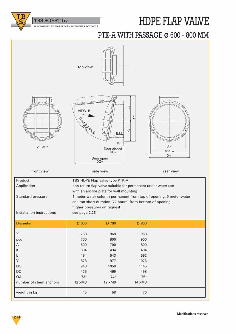
Product TBS HDPE Flap valve type PTK-A
Application non-return flap valve suitable for permanent under water use
with an anchor plate for wall mounting
Standard pressure 1 meter water column permanent from top of opening, 5 meter water
column short duration (72 hours) from bottom of opening
higher pressures on request
Installation instructions see page 2.25
Diameter Ø 600 Ø 700 Ø 800
X 768 868 968
pcd 700 800 900
A 600 700 800
K 384 434 484
L 494 543 592
Y 878 977 1076
DO 948 1050 1145
DC 425 469 498
OA 73° 74° 75°
number of chem anchors 12 xM8 12 xM8 14 xM8
weight in kg 45 58 70
Modifications reserved.2.15
HDPE FLAP VALVETBS SOEST bvbbR
SPECIALISED IN WATER MANAGEMENT PRODUCTS
PTK-A WITH PASSAGE ø 900 - 2000 MM
pcd. =
X=
A=15/20K
=L=
Y=
Door closedDC=
Door openDO=
VIEW P
VIEW P
B.I.L.
Opening angle
OA=
side view
top view
front view rear view
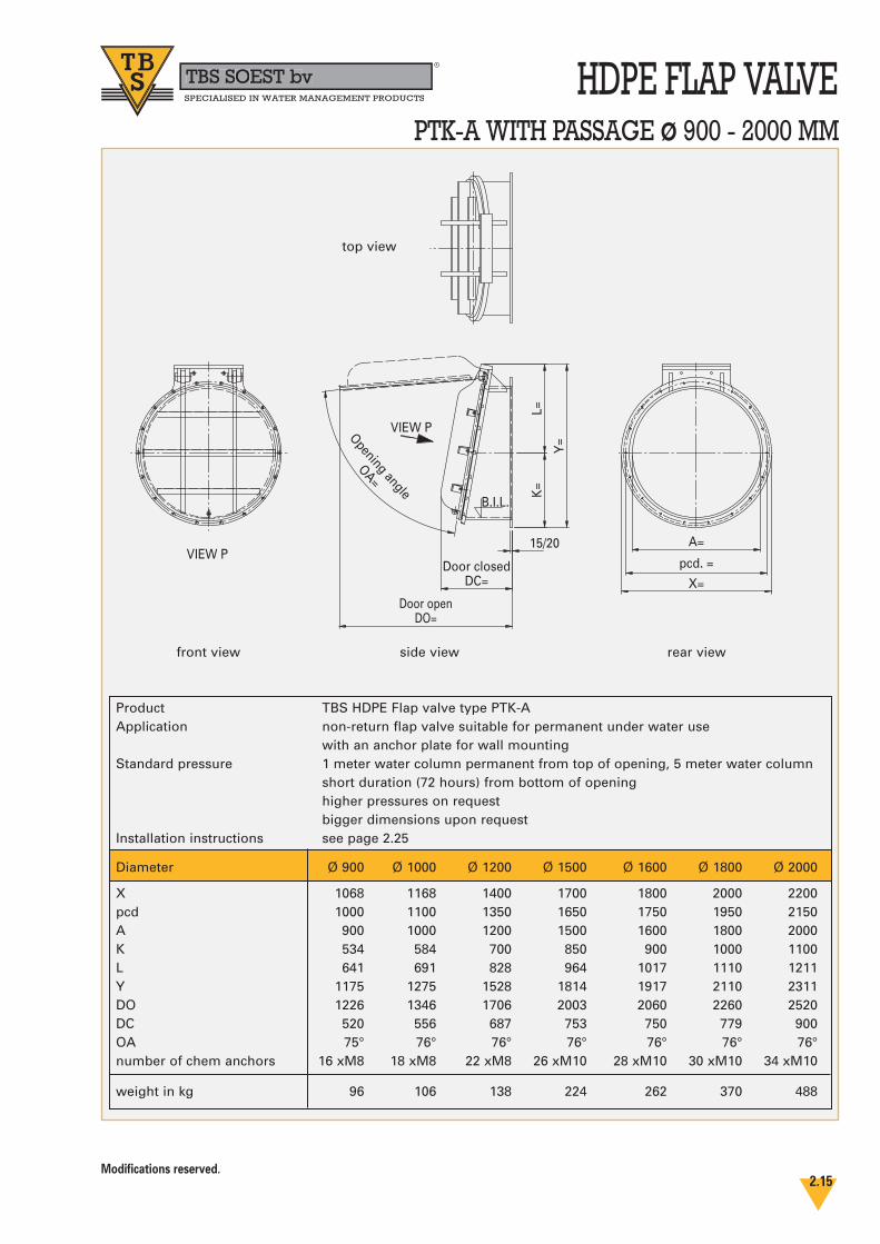
Product TBS HDPE Flap valve type PTK-AApplication non-return flap valve suitable for permanent under water use
with an anchor plate for wall mountingStandard pressure 1 meter water column permanent from top of opening, 5 meter water column
short duration (72 hours) from bottom of openinghigher pressures on requestbigger dimensions upon request
Installation instructions see page 2.25
Diameter Ø 900 Ø 1000 Ø 1200 Ø 1500 Ø 1600 Ø 1800 Ø 2000
X 1068 1168 1400 1700 1800 2000 2200pcd 1000 1100 1350 1650 1750 1950 2150A 900 1000 1200 1500 1600 1800 2000K 534 584 700 850 900 1000 1100L 641 691 828 964 1017 1110 1211Y 1175 1275 1528 1814 1917 2110 2311DO 1226 1346 1706 2003 2060 2260 2520DC 520 556 687 753 750 779 900OA 75° 76° 76° 76° 76° 76° 76°number of chem anchors 16 xM8 18 xM8 22 xM8 26 xM10 28 xM10 30 xM10 34 xM10
weight in kg 96 106 138 224 262 370 488

TBS SOEST bvbbR
SPECIALISED IN WATER MANAGEMENT PRODUCTS
Modifications reserved.2.16
HDPE FLAP VALVEPTK-A WITH RECTANGULAR PASSAGE DB X DH
Y=D
h+32
0
Dh=
X=Db+200
Db=
Z=10
0
Z=100
Dh+
200
Door closed (DC)
15
Door open (DO)
VIEW P
B.I.L.
Opening angle
OA=
side view
top view
front view
Product TBS HDPE Flap valve type PTK-A with rectangular / square opening
Application non-return flap valve suitable for permanent under water use with an anchor plate for wall mounting
Standard pressure 1 meter water column permanent from top of opening, 5 meter watercolumn short duration (72 hours) from bottom of openinghigher pressures on requestdepending upon seize door may be reinforced with stainless steel profiles
Installation instructions see page 2.25
Modifications reserved.2.17
HDPE FLAP VALVETBS SOEST bvbbR
SPECIALISED IN WATER MANAGEMENT PRODUCTS
PWK-F WITH PASSAGE ø 150 - 2000 MM
79
3 2 6 4 15
10 11
13PWK 500-800F
78
3 2 6 4 15
10 11
13 PWK ≥ 900F 3
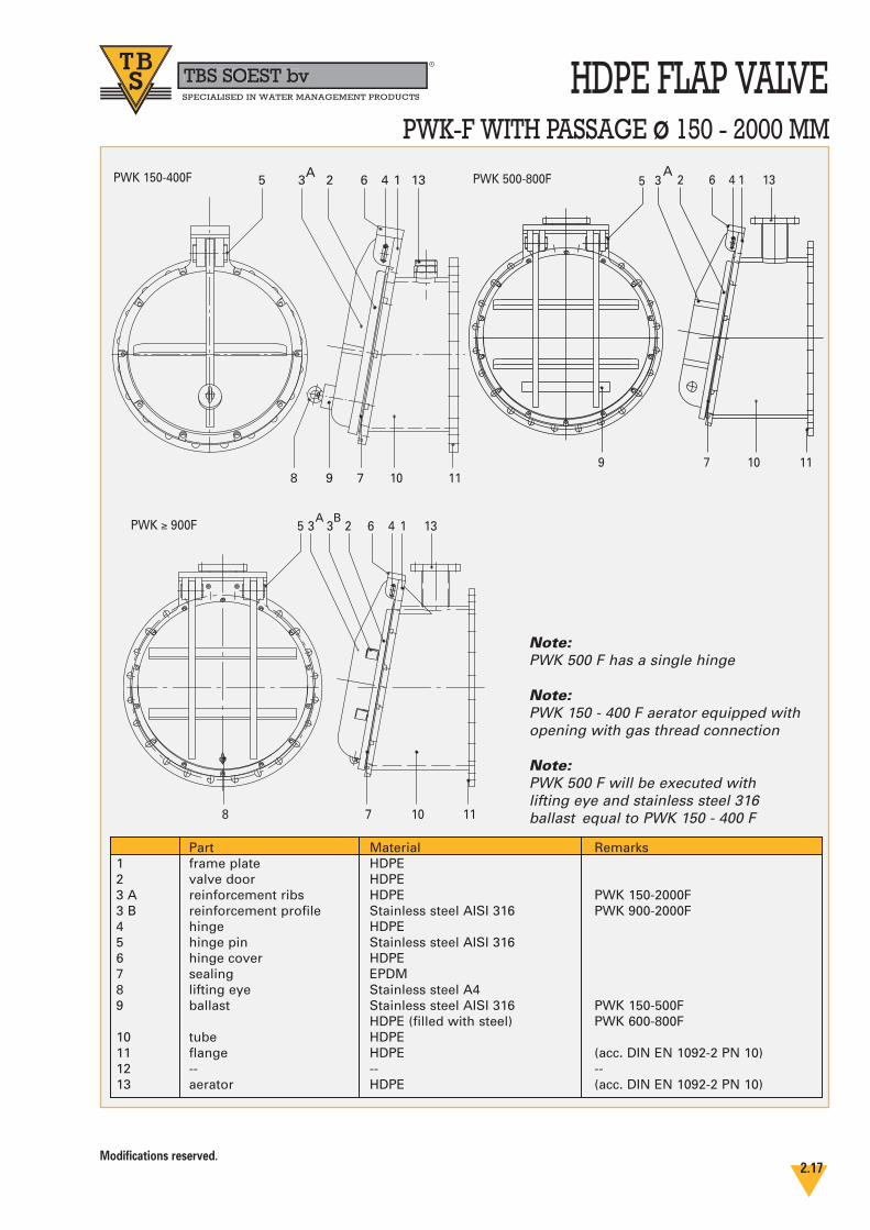
Note:PWK 500 F has a single hinge
Note:PWK 150 - 400 F aerator equipped withopening with gas thread connection
Note:PWK 500 F will be executed with lifting eye and stainless steel 316 ballast equal to PWK 150 - 400 F
Part Material Remarks1 frame plate HDPE2 valve door HDPE3 A reinforcement ribs HDPE PWK 150-2000F3 B reinforcement profile Stainless steel AISI 316 PWK 900-2000F4 hinge HDPE5 hinge pin Stainless steel AISI 3166 hinge cover HDPE7 sealing EPDM8 lifting eye Stainless steel A49 ballast Stainless steel AISI 316 PWK 150-500F
HDPE (filled with steel) PWK 600-800F10 tube HDPE11 flange HDPE (acc. DIN EN 1092-2 PN 10)12 -- -- --13 aerator HDPE (acc. DIN EN 1092-2 PN 10)
798
3 2 6 4 15
10 11
13PWK 150-400F A A
A B
TBS SOEST bvbbR
SPECIALISED IN WATER MANAGEMENT PRODUCTS
Modifications reserved.2.18
HDPE FLAP VALVEPWK-F WITH PASSAGE ø 150 - 400MM
pcd. =Df=
Fi=30
Door closedDC=
AO=
FLANGE PN 10ACC. DIN EN 1092-2
L=K
=
Y=
Door openDO=
Z=
VIEW P
VIEW P
Opening angle
OA= B.I.L.
side view
top view
front view rear view
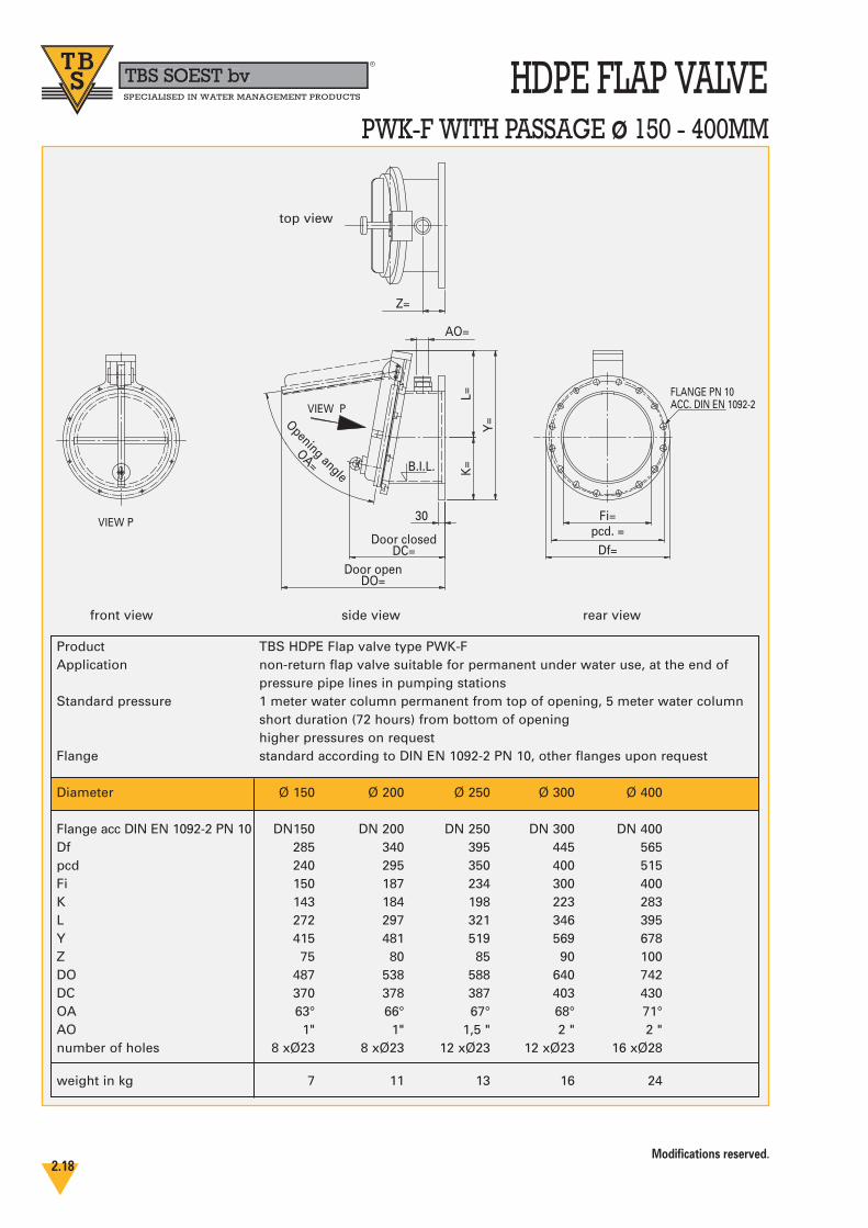
Product TBS HDPE Flap valve type PWK-FApplication non-return flap valve suitable for permanent under water use, at the end of
pressure pipe lines in pumping stationsStandard pressure 1 meter water column permanent from top of opening, 5 meter water column
short duration (72 hours) from bottom of openinghigher pressures on request
Flange standard according to DIN EN 1092-2 PN 10, other flanges upon request
Diameter Ø 150 Ø 200 Ø 250 Ø 300 Ø 400
Flange acc DIN EN 1092-2 PN 10 DN150 DN 200 DN 250 DN 300 DN 400Df 285 340 395 445 565pcd 240 295 350 400 515Fi 150 187 234 300 400K 143 184 198 223 283L 272 297 321 346 395Y 415 481 519 569 678Z 75 80 85 90 100DO 487 538 588 640 742DC 370 378 387 403 430OA 63° 66° 67° 68° 71°AO 1" 1" 1,5 " 2 " 2 "number of holes 8 xØ23 8 xØ23 12 xØ23 12 xØ23 16 xØ28
weight in kg 7 11 13 16 24

TBS SOEST bvbbR
SPECIALISED IN WATER MANAGEMENT PRODUCTS
Modifications reserved.2.19
HDPE FLAP VALVEPWK-F WITH PASSAGE ø 500 - 800 MM
B.I.L.
30Door closed
DC= pcd.=
Fi=
Df=
Z=
Q=
K=
L=
Y=
Door openDO=
Opening angle
OA=VIEW P
VIEW P
B.I.L.
FLANGE PN 10ACC. DIN EN 1092-2
AO=
FLANGE PN 10ACC. DIN EN 1092-2
side view
top view
front view rear view
Product TBS HDPE Flap valve type PWK-FApplication non-return flap valve suitable for permanent under water use, at the end
of pressure pipe lines in pumping stationsStandard pressure 1 meter water column permanent from top of opening, 5 meter water
column short duration (72 hours) from bottom of openinghigher pressures on request
Flange standard according to DIN EN 1092-2 PN10, other flanges upon request
Diameter Ø 500 Ø 600 Ø 700 Ø 800
Flange acc DIN EN 1092-2 PN 10 DN 500 DN 600 DN 700 DN 800 Df 670 780 895 1015pcd 620 725 840 950Fi 500 600 700 800K 335 390 448 508L 444 494 543 592Q 490 530 580 630Y 825 920 1028 1138Z 110 150 175 200DO 893 1044 1194 1345DC 534 523 612 698OA 72° 73° 74° 75°AO 66,4 79,8 97,4 124Aerator flange acc DIN EN 1092-2 PN 10 DN65 DN80 DN100 DN125 number of holes main flange 20 xØ28 20 xØ31 24 xØ31 24 xØ34number of holes aerator flange 4 xØ19 8 xØ19 8 xØ19 8 xØ19
weight in kg 32 45 60 77
Note: PWK 500 F will be executed with stainless steel 316 ballast with lifting eye, same as PWK 150 - 400 F
TBS SOEST bvbbR
SPECIALISED IN WATER MANAGEMENT PRODUCTS
Modifications reserved.2.20
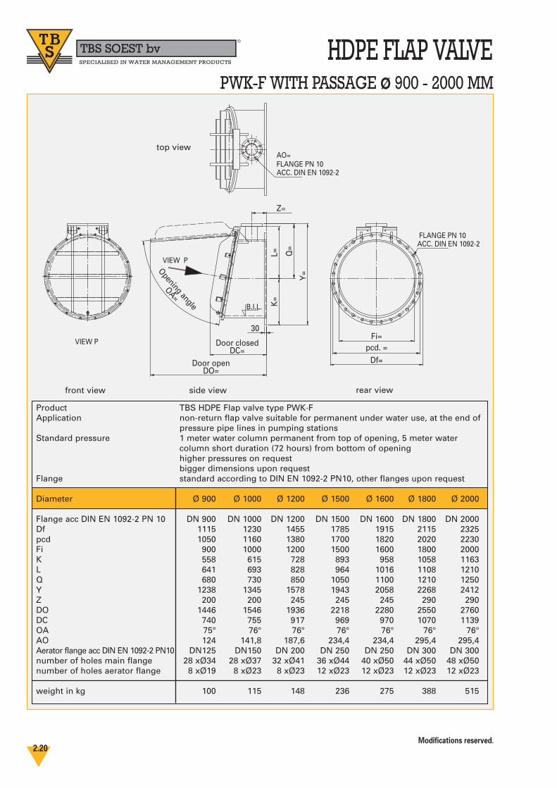
HDPE FLAP VALVEPWK-F WITH PASSAGE ø 900 - 2000 MM
30
Y=
K=
L=
Door openDO=
Door closedDC=
Fi=
Df=pcd. =
B.I.L.
Z=
VIEW P
VIEW P
Opening angle
OA=
Q=
AO=FLANGE PN 10ACC. DIN EN 1092-2
FLANGE PN 10ACC. DIN EN 1092-2
Product TBS HDPE Flap valve type PWK-FApplication non-return flap valve suitable for permanent under water use, at the end of
pressure pipe lines in pumping stationsStandard pressure 1 meter water column permanent from top of opening, 5 meter water
column short duration (72 hours) from bottom of openinghigher pressures on requestbigger dimensions upon request
Flange standard according to DIN EN 1092-2 PN10, other flanges upon request
Diameter Ø 900 Ø 1000 Ø 1200 Ø 1500 Ø 1600 Ø 1800 Ø 2000
Flange acc DIN EN 1092-2 PN 10 DN 900 DN 1000 DN 1200 DN 1500 DN 1600 DN 1800 DN 2000Df 1115 1230 1455 1785 1915 2115 2325pcd 1050 1160 1380 1700 1820 2020 2230Fi 900 1000 1200 1500 1600 1800 2000K 558 615 728 893 958 1058 1163L 641 693 828 964 1016 1108 1210Q 680 730 850 1050 1100 1210 1250Y 1238 1345 1578 1943 2058 2268 2412Z 200 200 245 245 245 290 290DO 1446 1546 1936 2218 2280 2550 2760DC 740 755 917 969 970 1070 1139OA 75° 76° 76° 76° 76° 76° 76°AO 124 141,8 187,6 234,4 234,4 295,4 295,4Aerator flange acc DIN EN 1092-2 PN10 DN125 DN150 DN 200 DN 250 DN 250 DN 300 DN 300number of holes main flange 28 xØ34 28 xØ37 32 xØ41 36 xØ44 40 xØ50 44 xØ50 48 xØ50number of holes aerator flange 8 xØ19 8 xØ23 8 xØ23 12 xØ23 12 xØ23 12 xØ23 12 xØ23
weight in kg 100 115 148 236 275 388 515
side viewfront view
top view
rear view
TBS SOEST bvbbR
SPECIALISED IN WATER MANAGEMENT PRODUCTS
Modifications reserved.2.21
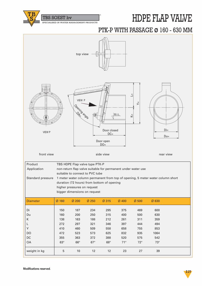
HDPE FLAP VALVEPTK-P WITH PASSAGE ø 160 - 630 MM
Di=Door closedDC=
L=K
=
Y=
Door openDO=
Du=VIEW P
VIEW P
B.I.L.
Opening angle
OA=
Product TBS HDPE Flap valve type PTK-P
Application non-return flap valve suitable for permanent under water use
suitable to connect to PVC tube
Standard pressure 1 meter water column permanent from top of opening, 5 meter water column short
duration (72 hours) from bottom of opening
higher pressures on request
bigger dimensions on request
Diameter Ø 160 Ø 200 Ø 250 Ø 315 Ø 400 Ø 500 Ø 630
Di 150 187 234 295 375 469 600
Du 160 200 250 315 400 500 630
K 138 163 188 212 261 311 359
L 272 297 321 346 397 444 494
Y 410 460 509 558 658 755 853
DO 472 523 573 625 832 935 1064
DC 355 363 372 388 520 575 542
OA 63° 66° 67° 68° 71° 72° 73°
weight in kg 5 10 12 12 23 27 39
side view
top view
front view rear view
TBS SOEST bvbbR
SPECIALISED IN WATER MANAGEMENT PRODUCTS
Modifications reserved.2.22
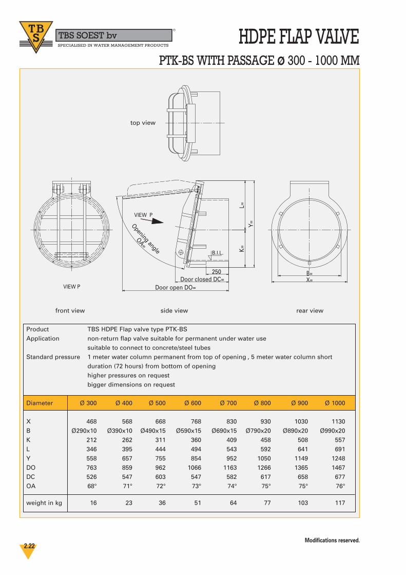
HDPE FLAP VALVEPTK-BS WITH PASSAGE ø 300 - 1000 MM
Door closed DC=B=X=
K=
L=Y
=Opening angle
OA=
Door open DO=
250
VIEW P
VIEW P
B.I.L.
Product TBS HDPE Flap valve type PTK-BS
Application non-return flap valve suitable for permanent under water use
suitable to connect to concrete/steel tubes
Standard pressure 1 meter water column permanent from top of opening , 5 meter water column short
duration (72 hours) from bottom of opening
higher pressures on request
bigger dimensions on request
Diameter Ø 300 Ø 400 Ø 500 Ø 600 Ø 700 Ø 800 Ø 900 Ø 1000
X 468 568 668 768 830 930 1030 1130
B Ø290x10 Ø390x10 Ø490x15 Ø590x15 Ø690x15 Ø790x20 Ø890x20 Ø990x20
K 212 262 311 360 409 458 508 557
L 346 395 444 494 543 592 641 691
Y 558 657 755 854 952 1050 1149 1248
DO 763 859 962 1066 1163 1266 1365 1467
DC 526 547 603 547 582 617 658 677
OA 68° 71° 72° 73° 74° 75° 75° 76°
weight in kg 16 23 36 51 64 77 103 117
side view
top view
front view rear view
TBS SOEST bvbbR
SPECIALISED IN WATER MANAGEMENT PRODUCTS
Modifications reserved.2.23
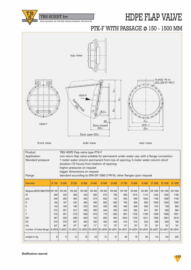
HDPE FLAP VALVEPTK-F WITH PASSAGE ø 150 - 1500 MM
30Door closed
DC=pcd. =
Fi=
Df=
K=
L=
Y=
Door open DO=
Opening angle
OA=
VIEW P
VIEW P
B.I.L.
FLANGE PN 10 ACC. DIN EN 1092-2
side view
top view
front view rear view
Product TBS HDPE Flap valve type PTK-FApplication non-return flap valve suitable for permanent under water use, with a flange connectionStandard pressure 1 meter water column permanent from top of opening, 5 meter water column short
duration (72 hours) from bottom of openinghigher pressures on requestbigger dimensions on request
Flange standard according to DIN EN 1092-2 PN10, other flanges upon request
Diameter Ø 150 Ø 200 Ø 250 Ø 300 Ø 400 Ø 500 Ø 600 Ø 700 Ø 800 Ø 900 Ø 1000 Ø 1200 Ø 1500
Flange acc DIN EN 1092-2 PN10 DN 150 DN 200 DN 250 DN 300 DN 400 DN 500 DN 600 DN 700 DN 800 DN 900 DN 1000 DN 1200 DN 1500
Df 285 340 395 445 565 670 780 895 1015 1115 1230 1455 1785
pcd 240 295 350 400 515 620 725 840 950 1050 1160 1380 1700
Fi 150 187 234 300 400 500 600 700 800 900 1000 1200 1500
K 143 184 198 223 283 335 390 448 508 558 615 728 893
L 272 297 321 346 395 444 493 543 592 641 691 828 964
Y 415 481 519 569 678 779 883 991 1100 1199 1306 1556 1857
DO 487 538 588 640 742 853 954 1054 1155 1251 1356 1661 2018
DC 370 378 387 403 430 493 433 475 510 545 565 642 769
OA 63° 66° 67° 68° 71° 72° 73° 74° 75° 75° 76° 76° 76°
number of holes flange 8 xØ23 8 xØ23 12 xØ23 12 xØ23 16 xØ28 20 xØ28 20 xØ31 24 xØ31 24 xØ34 28 xØ34 28 xØ37 32 xØ41 36 xØ44
weight in kg 6 9 12 15 23 31 47 60 76 99 110 142 229
TBS SOEST bvbbR
SPECIALISED IN WATER MANAGEMENT PRODUCTS
Modifications reserved.2.24
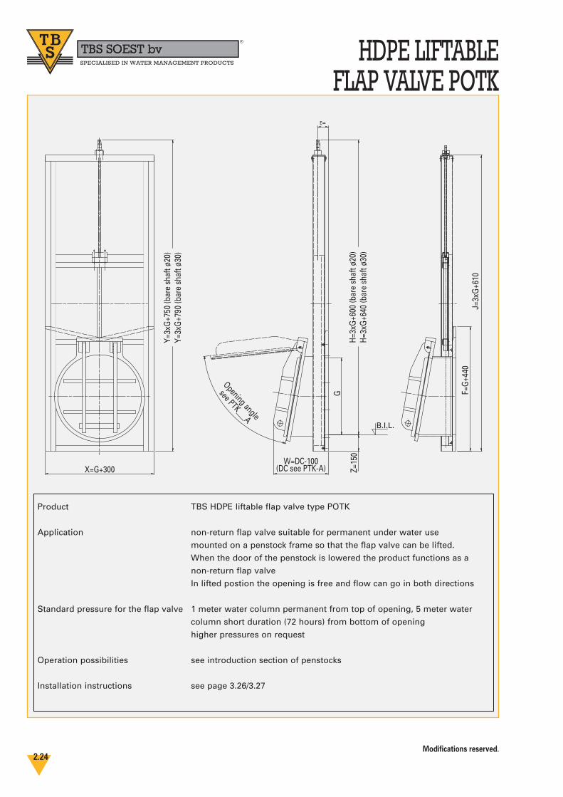
HDPE LIFTABLE FLAP VALVE POTK
B.I.L.
Opening angle
see PTK___A
X=G+300
Y=3x
G+7
50 (b
are
shaf
t ø20
)Y=
3xG
+790
(bar
e sh
aft ø
30)
E=
H=3x
G+6
00 (b
are
shaf
t ø20
)H=
3xG
+640
(bar
e sh
aft ø
30)
J=3x
G+6
10
G
Z=15
0
F=G
+440
W=DC-100(DC see PTK-A)
Product TBS HDPE liftable flap valve type POTK
Application non-return flap valve suitable for permanent under water use
mounted on a penstock frame so that the flap valve can be lifted.
When the door of the penstock is lowered the product functions as a
non-return flap valve
In lifted postion the opening is free and flow can go in both directions
Standard pressure for the flap valve 1 meter water column permanent from top of opening, 5 meter water
column short duration (72 hours) from bottom of opening
higher pressures on request
Operation possibilities see introduction section of penstocks
Installation instructions see page 3.26/3.27

TBS SOEST bvbbR
SPECIALISED IN WATER MANAGEMENT PRODUCTS
Modifications reserved.2.25
INSTALLATION
FLAP VALVE TYPE PTK-A / G
On delivery the customer must check the goodssupplied by TBS for completeness and damage orbreakages. If the goods are not complete or aredamaged, the customer must respond by return,but at the latest within 1 week after receipt of thegoods.
The customer can not claim under guarantee if:- these installation instructions are not strictly
followed.- on installation of the goods supplied the
conditions for installation did not conform with our installation manual.
- a third party has modified the goods suppliedby TBS.
PREPARING FOR INSTALLATION
- Before installation use a straightedge to check the smoothness of the wall at the location of the frame plate for the flap valve.
- Also check the concrete wall for small local pits and lumps so that the neoprene tape (which will be fixed to the back plate) can function properly and seal well between the frame plate and the wall.
INSTALLATION
- Mark the locations of the two anchor holes (outside the hinges on the frame) for the frame / anchor plate onto the wall.
- Drill these two holes and mount the anchors as instructed by the supplier of the chemical anchors. Note the time required for the har-dening of the chemical substance.
- Mount the flap valve by hanging it onto thesetwo anchors, after they have been fixed in place.
- Check that the flap valve is vertical and mark the locations of the remaining mounting holes onto the wall. Remove the flap valve.
- Drill the other holes and place the chemical capsules into the holes but not the anchor studs!!
- Fix the neoprene sealing tape supplied all around the opening and over the anchor holes at the back of the frame / anchor plate.
- Make the holes in the neoprene tape for the anchors.
- Hang the flap valve back on the wall on the two anchor bars.
- Mount the anchor studs as instructed by the supplier of the chemical anchors. Remove all material that comes out of the holes. Note thetime required for the hardening of the chemi-cal substance.
- Tighten the anchors gradually one by one so that a good seal to the wall is obtained without deforming the anchor plate. Check the smoothness.
- Check the frame plate is not deformed to the extent that the door of the flap valve does notseal against the rubber seal in the frame plate. (PTK-G)
COMMISIONING
- Remove all protection- Check the functioning of the flap valve by
opening and closing the door several times as there must be a sealing between the anchor / frame plate and the door.
SPECIAL CARE ABOUT CHEMICAL ANCHORS
INSTRUCTIONS
Installation diagram