Embed Size (px)
Citation preview

Risk-Based
Inspection
Trouble Shooting
Leaking Joints
Fixed Equipment NewsletterVolume 2019, October Issue
ASME Section VIII, Division 1 - Appendix 46
Flow Induced Vibrations in Heat Exchangers
Serving the Fixed Equipment Community Since 2007
Sponsored by


Fixed Equipment Newsletter October 2019 ♦ 3
From The Editor’s Desk:
All industrial equipment require periodic maintenance to ensure the unit is in proper
functioning condition. This is especially true with pressure vessels as the operating
conditions in which these vessels are subject to can generate wear and other concerns
under normal conditions.
Maintenance is not confined to corrective measures or to correct operating deficiencies. All
safety precautions and maintenance tips described below should be observed to avoid
harm when using pressure vessels.
Maximize Awareness: It is essential that maintenance personnel get a complete briefing on the contents of each
pressure vessel.
Replace When Necessary: Some industries practice a “replace when needed” maintenance program which
allows wear to exceed 75% or more before replacing the part. A better approach is “replace when necessary”
which allows wear of up to only 50%. This prevents failures before they occur.
Inspect it Anyways: Each inspection should be as thorough as possible. Even if it was just inspected, inspect it
anyways. Pressure vessels operate under dynamic conditions and loads, and while a previous inspection did not
reveal any concerns, the situation may have changed.
Protective Device Installation: Installing protective devices helps ensure that the pressure vessel meets the
challenges of daily use.
Follow All Safety Protocols: During the maintenance cycle, all rules and protocols that also take into account
the execution of follow up measures must be followed. All safety features on the equipment must be inspected
and tested to make sure they are in functioning order.
A proper inspection regimen with rigorous maintenance schedule will not only save your company money over the
life of the pressure vessel but it will also go a long way to reducing any potential liability during the operation of
the pressure vessel.
Ramesh K Tiwari
THE GRAPHIC ON THE COVER PAGE HAS BEEN PROVIDED BY MUNTERS IN FORT MYERS, FLORIDA.
In this issue…
ASME SECTION VIII, DIVISION 1 - APPENDIX 46 Page 5
FLOW INDUCED VIBRATION IN HEAT EXCHANGERS Page 9
RISK-BASED INSPECTION Page 21
TROUBLE SHOOTING LEAKING JOINTS Page 29

Pressure Vessel Newsletter October 2017 ♦ 4
This page left intentionally blank.

Fixed Equipment Newsletter October 2019 ♦ 5
ASME SECTION VIII, DIVISION 1 - APPENDIX 46
When is Appendix 46 of ASME Section VIII, Division 1 applicable?
Appendix 46 is applicable when using Division 2 to establish the thickness and other design details of a component
for a Section VIII, Division 1 pressure vessel.
What are the allowable stress values and the weld joint efficiencies used when applying Appendix 46?
ASME Section VIII, Division 2 allows the use of “Design by Rules” and/or “Design by Analysis” for design and
construction of pressure vessels. Design by Rules requires adhering to Part 4 of the Code and Design by Analysis
requires adhering to Part 5 of the Code. Therefore, when applying Appendix 46, the designer has choice of using
Part 4 and/or Part 5 of the Code.
a. When Part 4, Design by Rule is used, the design shall be in accordance with paragraph 46-3.
i. The allowable stress shall be in accordance with UG-23, except that the maximum allowable
compressive stress shall be limited as prescribed in Division 2, paragraph 4.4.12 in lieu of the
rules of UG-23(b).
ii. The weld joint efficiency shall be established in accordance with UW-11 and UW-12.
b. When Part 5, Design by Analysis is used, the design shall be in accordance with paragraph 46-4.
i. The allowable tensile stress shall be in accordance with UG-23.
ii. The weld joint efficiency shall be established in accordance with the full radiography requirements
of UW-11 and UW-12.
DESIGN BY RULE
When “Design by Rule” requirements in Division 2, Part 4 are used to design the components for a Division 1
pressure vessel, the following conditions shall be met:
a. If the thickness of a shell section or formed head is determined using the design rules in Division 2,
paragraph 4.3 or 4.4
1. For design of nozzles, any nozzle and its reinforcement attached to that shell section or formed
head shall be designed in accordance with Division 2, paragraph 4.5.
2. For conical transitions, each component comprising the cylinder-to-cone junction shall be
designed in accordance with Division 2, paragraph 4.3 or 4.4.
3. Material impact test requirements shall be in accordance with the rules of Division 1, except that
the required thickness used in calculating the coincident ratio under the rules of UCS-66(b) or
UCS-66(i) shall be calculated in accordance with the rules of Division 2.
b. The fabrication tolerances specified in Division 2, paragraphs 4.3.2 and 4.4.4 (as applicable) shall be
satisfied. The provision of Division 2, paragraph 4.14, Evaluation of Vessels Outside of Tolerance, is not
permitted.
c. When using the rules of Division 2, Part 4, the full set of design loads and load case combinations in
paragraph 4.1.5.3 are not required except when necessary to satisfy the requirements of UG-22. When
Fixed Equipment Newsletter October 2019 ♦ 6
the design load combinations of Division 2, Table 4.1.2 are used, the allowable stress increase of UG-
23(d) is not permitted.
1. The factors present in Division 2, Table 4.1.1 for wind loading, W, are based on ASCE/SEI 7-10
wind maps and probability of occurrence. If a different recognized standard for wind loading is
used, the User shall inform the Manufacturer of the standard to be applied and provide suitable
load factors if different from ASCE/SEI 7-10.
2. The factors present in Division 2, Table 4.1.1 for earthquake loading, E, are based on ASCE/SEI
7-10. If a different recognized standard for earthquake loading is used, the User shall inform the
Manufacturer of the standard to be applied and provide suitable load factors if different from
ASCE/SEI 7-10.
d. Evaluation of the stresses during the test condition of Division 2, paragraph 4.1.6.2 is not required.
However, such calculations may form the basis of a calculated test pressure as described in UG-99(c) or
UG-100(b).
e. The fatigue screening criterion of Division 2, paragraph 4.1.1.4 is not required. However, it may be used
when required by UG-22.
f. Weld joint details shall be in accordance with Division 2, paragraph 4.2, with the exclusion of Category E
welds.
DESIGN BY ANALYSIS
When “Design by Analysis” requirements in Division 2, Part 5 are used to design the components for a Division 1
pressure vessel, the following conditions shall be met:
a. Division 2, Part 5 shall not be used in lieu of the design thickness requirements of Division 1 or Division
2, Part 4.
b. The allowable stress increase of UG-23(d) is not permitted.
c. All of the failure modes listed in Division 2, Part 5 shall be considered.
1. When demonstrating protection against plastic collapse in Division 2, paragraph 5.2, the load case
combinations of Division 2 shall be considered in addition to any other combinations defined by
the User. In evaluating load cases involving internal and external specified design pressure, P,
additional cases with P equal to zero shall be considered.
i. When applying the elastic stress analysis method in Division 2, paragraph 5.2.2, the
allowable stress, S, shall be as per 46-2(a).
ii. When applying the limit-load analysis method in Division 2, paragraph 5.2.3, the yield
strength defining the plastic limit shall equal 1.5S, where S shall be as per 46-2(a).
iii. When applying the elastic–plastic stress analysis method in Division 2, paragraph 5.2.4,
in conjunction with Division 2, Table 5.5, β shall equal 3.5.
iv. Evaluation of the test condition is not required [see 46-3(d)].
2. When demonstrating protection against local failure in Division 2, paragraph 5.3, the load case
combination of Division 2 shall be considered. The exemption provided in Division 2, paragraph
5.3.1.1 is applicable to weld details in Division 2, Part 4 only. There exist weld details in Division
1 that are not permitted in Division 2 [subject to the provision in 46-3(f)]; those details are not
exempt from evaluation of protection against local failure.

Fixed Equipment Newsletter October 2019 ♦ 7
3. When demonstrating protection against collapse from buckling in Division 2, paragraph 5.4, the
design margin of the Division 2 assessment procedure shall be used.
4. When demonstrating protection against failure from cyclic loading: ratcheting in Division 2,
paragraph 5.5.6 or 5.5.7, the design margin of the Division 2 assessment procedure shall be used,
except that where it is used, the allowable stress, S, shall be per 46-2(a).
The assessment procedure for this failure mode requires the use of operating load ranges. This
requires information on the operating load cycle, which shall be provided by the User. In the
absence of such information, the Designer may use his or her judgment to determine the worst
case, taking into consideration the vector nature of certain loads and their potential reversal, as
well as pressure cycles that may include vacuum conditions.
5. When demonstrating protection against failure from cyclic loading: fatigue in Division 2,
paragraphs 5.5.3, 5.5.4, or 5.5.5, the design margin of the Division 2 assessment procedure shall
be used, except that where it is used, the allowable stress, S, shall be per 46-2(a).
The assessment procedure for this failure mode requires the use of operating load ranges. This
requires information on the operating load cycle, which shall be provided by the User. In the
absence of such information, the Designer may use his or her judgment to determine the worst
case, taking into consideration the vector nature of certain loads and their potential reversal, as
well as pressure cycles that may include vacuum conditions.
References:
ASME Boiler and Pressure Vessel, Section VIII, Division 1 - 2019 Edition

Fixed Equipment Newsletter October 2019 ♦ 8
This page left intentionally blank.

Fixed Equipment Newsletter October 2019 ♦ 9
FLOW INDUCED VIBRATION IN HEAT EXCHANGERS
INTRODUCTION
Along with heat transfer and pressure drop, tube vibration is one of the primary factors controlling the design of
shell-and-tube heat exchangers. Tubes are usually the most flexible part of an exchanger and most susceptible to
vibration. They vibrate at their natural frequencies as a result of shell-side fluid flowing past them. In most
exchangers, the intensity of vibration is so low that it does not create a problem. Vibration becomes a problem
when the intensity increases to the point that it causes some part of the exchanger to fail mechanically - the
vibrating tubes impact with baffles, with the heat exchanger shell, or with one another. Extreme tube vibrations
lead to leaks in the tubes or tube joints. The result is that the exchanger must be taken out of service for repair
and modification.
Tubes vibrate at discrete frequencies depending primarily on their geometry, means of support, and material of
construction. The lowest frequency at which tubes vibrate is called their fundamental natural frequency. The
intensity of this vibration is evidenced by the amount of periodic movement of the tube, with the largest movement
usually at midspan between supports. The extent of this peak-to-peak movement about the at-rest centerline is
termed the amplitude of vibration. Energy must be fed to the tubes to excite them into vibration. This energy is
provided by flow parallel to or across the tubes. Internal and external damping dissipate the energy. Prolonged
tube vibration with large amplitudes leads to the mechanical failure of tubes, which then permits leakage between
the shellside and tube-side fluids. Mechanical failure usually occurs by one or more of the following:
Collision Damage
If the amplitude of vibration is sufficiently large, adjacent tubes impact with one another or against the shell
and emit a loud noise. The tube walls can be worn thin with time and eventually split open. Tube impact
produces characteristic diamond-shaped wear patterns at the midspans of the tubes,
Baffle Damage
Baffle holes are made larger than tubes to facilitate exchanger bundle assembly, and thus the tubes are free
to move at the baffles. The walls of vibrating tubes can be cut by the baffle, especially when the baffles are
thin and made from a harder material than the tubes. The cutting action reduces the tube wall until leakage
occurs.
Fatigue
Repeated bending of the tubes can lead to a breakdown of the tube material if the stresses are high enough
and the vibration continues for a sufficiently long time. Fatigue failure can be accelerated by corrosion and
erosion. This type of failure results in cracks or in pieces of the tube wall actually breaking off.
Tube Joint Leakage
The joint between the tube and tubesheet can fail due to vibration whether welded or expanded.
In addition, vibration failure results from the cutting action of the edge of the tube holes against the tube wall where
the tubes emerge from the tubesheet.
Although tube vibration failures have been reported in different parts of an exchanger, regions of long spans and
high local velocities are particularly susceptible. The largest number of reported tube failures occurs in tubes that
are within two or three tube rows of the tips of baffles, where the flow velocity is usually very high.

Fixed Equipment Newsletter October 2019 ♦ 10
TUBE BUNDLE VIBRATION CHARACTERISTICS
Every component of a shell-and-tube heat exchanger vibrates at its own unique natural frequency. Tubes are the
most flexible and thus the most easily excited. Tubes can and do vibrate at different frequencies. The lowest
natural frequency is called the fundamental or first mode. The higher natural frequencies are referred to as the
second mode, third mode, and so on. For conservative design purposes the fundamental frequency will be
emphasized and will be called simply the natural frequency of the tubes.
The natural frequency of tubes like that of a simple beam depends on the way the ends are fixed (clamped or
simply supported), the type of intermediate supports (simply supported, pinned, or clamped), the tube cross-
sectional geometry, the number of spans, the materials of construction, and the length of spans. Although the
natural frequency of the tubes can be measured experimentally, predictive methods are used to give approximate
values of the natural frequency.
Tubes are rigidly fastened to the tubesheets and supported at intermediate points along their length by baffles or
support plates. Some tubes in the center of a bundle may be supported by every baffle, whereas tubes that pass
through baffle windows may be supported only by every second or third baffle. Furthermore, end baffle spacings
are often longer than central baffle spacings to accommodate the nozzles and the shell flanges. Thus, the lengths
of the spans are seldom uniform along the length of a tube, and not all tubes in a bundle are supported by the
same number of baffles. This results in tubes with different natural frequencies in the same exchanger.
STRAIGHT-TUBE NATURAL FREQUENCIES
Several different approaches can be used to predict the natural frequency of straight tubes. Most start with the
assumption of a uniform beam clamped at least at one end with intermediate supports along its length. The
rigorous approach considers spans of unequal length between supports by writing the governing differential
equation of motion for each span separately. The solution is obtained through the use of the boundary conditions
at the ends of the tube and by relating the deflections and slopes at each intermediate support. This yields a set
of linear homogeneous equations in the constants. The determinant of the coefficients is set equal to zero to yield
the characteristic or frequency equation from which the natural frequency can be derived. The coefficients and
graphic solutions are available for determining the natural frequency of tubes with various combinations of spans
with two different lengths. The computer-plotted graphs for the shape of the various span configurations of
maximum deflection are also available. Computer programs, using the finite element approach, can provide
accurate determination of the natural frequencies and mode shapes for tubes with unequal spans and varying
degrees of intermediate restraint. Figure 1 is an example of the results from such a detailed analysis.
A somewhat less accurate, but normally adequate approach assumes that all spans are of equal length L. The
natural frequency fn is given by the equation
fn = 73.03Cn
L2 √EI
Me
where, E = Modulus of elasticity of tube material,
I = Area moment of inertia, and
Me = Effective mass per unit length.
Me is made up of three parts the mass per unit length of the tube, the mass of the fluid inside the tube, and the
virtual mass per unit length of tube for the shell-side fluid displaced by the tube.
The frequency constant Cn depends on the way the ends of the tube are fastened, the number of spans, and the
type of intermediate supports. Values of Cn, for tubes clamped at the ends with simple intermediate supports are
listed in Table 1. In addition to the values for the fundamental natural frequency (mode 1), the values for the higher
natural frequencies (modes 2, 3, 4, etc.) are shown. Notice that with more than four spans the difference in Cn,

Fixed Equipment Newsletter October 2019 ♦ 11
between successively higher modes becomes small. Further, the separation between the fundamental and the
several higher-mode natural frequencies becomes small once the number of spans exceeds eight. Thus, for the
design of most exchangers, only the lowest natural frequency of the tubes needs to be considered.
Figure 1: Natural Frequencies and Mode Shapes for a Tube with Uneven Length and
Different Rotational Stiffness at Supports
Table 1: Frequency Constant Cn for Uniform Beams of Equal Span Length Simply Supported with Extreme
Ends Clamped
Number of Spans Mode
1 2 3 4 5
1 12.36 198.34 388.75 642.63 959.98
2 49.59 12.36 160.66 198.34 335.20
3 40.52 59.56 72.36 143.98 178.25
4 37.02 49.59 63.99 72.36 137.30
5 34.99 44.19 55.29 66.72 72.36
6 34.32 40.52 49.59 59.56 67.65
7 33.67 38.40 45.70 53.63 62.20
8 33.02 37.02 42.70 49.59 56.98
9 33.02 35.66 40.52 46.46 52.81
10 33.02 34.99 39.10 44.19 49.59
11 32.37 34.32 37.70 41.97 47.23
12 32.37 34.32 37.02 40.52 44.94
The number of spans depends on the baffle arrangements and location of the tubes in the bundle. Most heat
exchangers have their longest unsupported spans passing through the baffle windows and/or in the end zones.
Fixed Equipment Newsletter October 2019 ♦ 12
Segmental and double-segmental baffle arrangements result in window spans supported by every other baffle,
whereas triple-segmental baffle arrangements are supported by every third baffle. Cross-flow exchangers and no-
tubes-in-window exchangers provide support at each baffle and support plate. In the same bundle the number of
spans may differ by one or two and the associated longest span lengths will vary. Since the natural frequency
depends on both the length of span and the number of spans (see Table 1), all combinations in the bundle should
be checked to determine the one that produces the lowest natural frequency.
a. Tube-to-baffle hole clearance effect on natural frequencies
Normal tube-to-baffle hole manufacturing clearances result in the baffles acting like simple supports. It has
been found experimentally that the clearance has to be reduced to nearly a pressed fit before there was any
appreciable change in the natural frequency. For most exchangers, the tube-to-baffle hole clearance is not a
significant parameter for controlling the natural frequency, but it may be important in determining damping and
tube wear.
b. Axial stress effect on natural frequencies
The tubes in a heat exchanger bundle may be under a tension or compression axial loading due to
manufacturing procedures and/or to operating temperatures and pressures. Assuming that the axial force Pa,
is known, the following equation can be used to adjust the natural frequency:
(fn)s = fn√1 +PaL2
EIπ2
The sign for axial force Pa, is minus when it is compressive and plus when it is tensile. Thus, tension increases
the natural frequency, whereas compression decreases it. The natural frequency due to axial loading in a
typical heat exchanger varies by as much as ±40%. Not knowing or considering the axial loading can lead to
serious inaccuracy of natural frequency predictions.
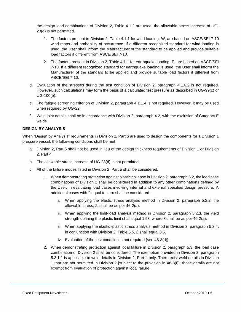
c. Finned-tube natural frequencies
To calculate the natural frequency of finned tubes, the area moment of inertia must be calculated using an
effective diameter for the outside diameter. For low-finned tubes typically used in shell-and-tube exchangers,
a value of about 8% thicker wall for the finned section should be used along with the actual inside diameter
under the finned section to calculate the area moment of inertia. The mass of the tube per unit length term in
the effective mass Me, should be the actual mass for the finned section. The fins on tubes should not alter the
assumed simple support constraint at the baffles.
Figure 2: TEMA Maximum Unsupported Length for Plain Tubes and Finned Tubes

Fixed Equipment Newsletter October 2019 ♦ 13
d. Span lengths
Of the variables that affect the natural frequencies, none is as influential as the length of the unsupported
spans. The natural frequency varies as the reciprocal of the span length squared. Early in the 1940s the TEMA
Standards somewhat arbitrarily placed maximum allowable unsupported spans for different tube sizes and
tube materials. Figure 2 is a plot of these maximum lengths. By coincidence, these lengths have prevented
many serious tube vibration problems. However, the current trends toward higher velocities to improve heat
transfer and minimize fouling make the TEMA maximum spans marginal for many exchangers. The current
trend is to limit maximum spans to 80% of the TEMA values, which increases the natural frequency by more
than 50%.
NATURAL FREQUENCIES OF U-TUBE BENDS
The vibration characteristics of a U tube are more difficult to predict than those of a straight tube. A simplified
approach is used that considers the straight portions and the bend separately. The straight portion is handled the
same as straight tubes. The bend portion uses a method that is included in the TEMA Standards. Assuming simple
supports for the first-mode U-tube out-of-plane, natural frequency can be calculated by the following:
fnu = 59.55Cu
R2 √EI
Me
where Cu, is the first-mode U-tube constant as shown in Figure 3, and R is the tube bend radius. This simplified
approach does not consider intermediate supports around the bend for U tubes that materially increase the natural
frequencies by stiffening the overhung section of the bundle. However, this complicates the prediction of the
natural frequencies as the extent of their effectiveness is uncertain.
AMPLITUDE OF TUBE VIBRATION
The natural frequencies are characteristics of the tubes themselves and are independent of the way they are
excited or the amplitude of vibration. On the other hand, the amplitude depends on the natural frequency of the
tubes, the mode shape, the frequency and the strength of the exciting mechanism, and the internal and external
system damping.
Figure 3: U-tube Natural Frequency Constant for First-mode Out-of-plane Vibration
The tubes in many shell-and-tube heat exchangers vibrate, but the amplitude is so small that the vibration is not
a problem. For the amplitude to become appreciable the system damping must be small and the energy input
large. For forced vibration of lightly damped structures when the ratio of the forcing frequency to the natural

Fixed Equipment Newsletter October 2019 ♦ 14
frequency approaches unity, resonance occurs with an attendant amplification of the amplitude. Thus, if the forcing
frequency can be kept appreciably below the natural frequency, the amplitude of vibration will be small.
Amplitudes as large as half the gap distance between adjacent tubes lead to impact collisions. Lesser amplitudes
can cause tube cutting by the baffles or failure of the tube joints.
SYSTEM DAMPING
System damping has a strong influence on the amplitude of vibration. In any real system, once the energy exciting
the vibration ceases, the amplitude of vibration decays with time. The rate at which the vibration dampens out is
often exponential. The logarithm of the difference in successive amplitude peaks is called the log decrement δo
and is an indication of the damping. The higher the value of the log decrement, the more heavily damped the
system is. Most tubes in heat exchangers are very lightly damped structures with low values of the log decrement.
Damping depends on the mechanical properties of the tube material, the geometry of the intermediate supports,
and the physical properties of the shell-side fluid. Tight tube-to-baffle clearances and thick baffles increase
damping, as does a very viscous shell-side fluid. The log decrements for copper-nickel finned tubes of 0.032 in
still air have been measured. No method is available for predicting the log decrement, although the range of values
most probably lies between 0.01 and 0.17 for tubes in heat exchanger bundles.
In the flow-induced vibration situation, if the energy input cannot be dissipated through damping, the amplitude of
vibration will increase with time leading to a runaway condition. If there is a balance, the amplitude remains
constant. If the damping exceeds the energy input, the amplitude diminishes with time.
SHELL-SIDE VELOCITIES IN SHELL-AND-TUBE HEAT EXCHANGERS
All predictive methods for flow-induced vibration contain a velocity term. The stream analysis method provides a
procedure for determining the fraction of the total that flows in each of five shell-side streams. These streams are
the main cross flow, the bundle-to-shell leakage, the baffle-to-shell leakage, the tube-to-baffle leakage, and the
bypass stream in any lane due to tube-pass partitions parallel to the crossflow velocity. In most industrial heat
exchangers, the main cross flow is considerably less than the total flow. Further, as the shell-side fluid flows
through a bundle of tubes, the velocity is constantly changing in magnitude and direction.
CROSS-FLOW VELOCITIES
The definition for cross-flow velocity used by most investigators of flow-induced vibration is based on the minimum
flow area through a tube row perpendicular to the primary direction of flow. For an ideal tube bank the selected
velocity is well defined. However, for a shell-and-tube exchanger it is somewhat ambiguous, as the number of
tubes in each row varies from baffle tip to baffle tip. In order to be consistent, the crossflow velocity for shell-and-
tube exchanger vibration prediction will be based on an integrated average area between the maximum and
minimum number of tubes in the rows between baffle tips, on the gaps between adjacent tubes in a tube row, and
on the cross-flow fraction of the total flow.
PARALLEL-FLOW VELOCITIES
The flow components parallel to the tubes include baffle-to-shell leakage streams, tube-to-baffle hole leakage
streams, and most important, the flow through the baffle windows. The parallel-flow velocity is usually assumed to
be the total cross flow plus the bundle-to-shell leakage stream flowing through the net window area. The parallel-
flow velocities for multi-segmental baffle exchangers are particularly difficult to define.
LEAKAGE AND BYPASS STREAM VELOCITIES
The leakage and bypass streams in a shell-and-tube heat exchanger are often disregarded, as they can be
predicted only by a technique such as a stream analysis method. These streams can have velocities as much as
10 times higher than the main cross-flow velocity. Many of the tubes that have failed were in the proximity of one
of these secondary flow streams. Heavy fouling can block the leakage through the tube-to-baffle clearances.

Fixed Equipment Newsletter October 2019 ♦ 15
ENTRANCE AND ESCAPE VELOCITIES
The fluid entering the shell through the inlet nozzle impinges directly on the first row of tubes under the nozzle
unless some type of impingement device is present. This device can be a row of dummy tubes, a solid plate, a
perforated plate, or some type of bar grid. With an impingement device the bundle entrance velocity should be
limited. This may require the removal of several rows of tubes to provide sufficient area between the bottom of the
nozzle and the impingement device. The TEMA Standards specifies that the bundle entrance ρu2 should not
exceed 6,000 kg/ms2. With impingement plates a region of high velocities may be found near the first rows of
tubes below the impingement plate in the bundle-to-shell clearance areas. The flow in the end zone between the
inlet and the fast baffle window is very difficult to analyze because of the large number of possible flow paths.
There can be areas where the flow is anything from highly turbulent to nearly stagnant.
At the exit of the exchanger a sufficient escape area must be provided to prevent velocities from being high enough
to initiate vibration in this region. These potentially troublesome areas are not easily analyzed and are often
overlooked in a check for vibration problems.
TURNAROUND VELOCITIES
It is important to understand the flows in the baffle window turnaround regions, as most of the tubes that fail pass
through them. Here the flow makes a reversal of direction between each cross pass. Velocity is continually
changing in both magnitude and direction, Even though the flow at any point can be separated into its cross-flow
and parallel-flow components, it is uncertain how to use these in the various predictive methods.
FLOW INDUCED VIBRATION PHENOMENA
There are several recognized phenomena that are associated with flow-induced vibration. These include vortex
shedding, fluid elastic instability, turbulent buffeting, parallel-flow eddy formation, and acoustic vibration. Since any
one of these can produce a flow-induced vibration problem, each must be considered in any comprehensive
vibration analysis of a shell-and-tube heat exchanger.
VORTEX SHEDDING
Flow across a tube produces a series of vortices in the downstream wake formed as the flow separates alternately
from the opposite sides of the tube as shown in Figure 4. This shedding of vortices produces alternating forces,
which occur more frequently as the velocity of flow increases. For a single cylinder the tube diameter, the flow
velocity, and the frequency of vortex shedding fvs can be described by the dimensionless Strouhal number Sr:
fvs =Sr . uc
Do
For single cylinders, the vortex shedding Strouhal number is a constant with a value of about 0.2. Vortex shedding
occurs for the range of Reynolds number 100 < Re < 5 X 10⁵, and >2 X 10⁶, whereas it dies out in between. The
gap is due to a shift of the flow separation point in vortices in the intermediate trans-critical Reynolds number
range.
Figure 4: Sketch of Vortex Shedding Resulting from Flow across a Tube

Fixed Equipment Newsletter October 2019 ♦ 16
Vortex shedding has also been observed for flow across ideal tube banks. The Strouhal number is no longer a
constant, but varies with the arrangement and spacing of the tubes. Vortex shedding is fluid mechanical in nature
and does not depend on any movement of the tubes. For a given arrangement and tube size, the frequency of the
vortex shedding for non-vibrating tubes increases as the velocity increases. The vortex shedding can excite tube
vibration when it matches the natural frequency of the tubes. The vortex shedding frequency can become locked
in to the natural frequency of a vibrating tube even when the flow velocity is increased. The movement of the tube
organizes the separation of the vortexes leaving the vibrating tube.
The values of the Strouhal number for ideal tube banks are nearly constant for a wide range of Reynolds numbers,
but vary considerably with longitudinal and transverse tube spacing.
TURBULENT BUFFETING
Extremely turbulent flow of the shell-side fluid contains a wide spectrum of frequencies distributed around a central
dominant frequency, which increases as the cross-flow velocity increases. This turbulence buffets the tubes, which
selectively extract energy from the turbulence at their natural frequency from the spectrum of frequencies present.
This is an extremely complex form of excitation. The dominant frequency for turbulent buffeting ftb is as follows:
ftb = [0.28 + 3.05 ucDo
lt (1 −
Do
t)
2]
About the central dominant frequency for turbulent buffeting, there is a band of frequencies of lesser energy
content. The turbulent energy spectrum can be represented by a square band bounded by frequencies ±9 Hz
about the central frequency.
When the dominant frequency for turbulent buffeting nearly matches the natural frequency, a considerable transfer
of energy is possible leading to significant vibration amplitudes.
The above equation is not recommended when the shellside fluid is a liquid. This is not to say that turbulent
buffeting cannot occur for liquids, but rather that the empirical predictions equation is based only on tests using
gases as the shell-side fluid.
FLUID ELASTIC WHIRLING
Fluid elastic whirling is evidenced by tubes vibrating in an orbital motion. This motion is produced by flow across
the tubes causing a combination of lift and drag displacements of the tubes at their natural frequencies. Typically,
once fluid elastic whirling commences, it can lead to a runaway condition if the energy fed to the tubes exceeds
that which can be dissipated by damping. The critical cross-flow velocity ucrit above which fluid elastic whirling can
develop is given by the following equation:
ucrit = βfnDo√Meδo
ρsDo2
where β is the fluid elastic instability threshold constant and δo is the log decrement for the tube bundle in the
shell-side fluid under static (no-flow) conditions.
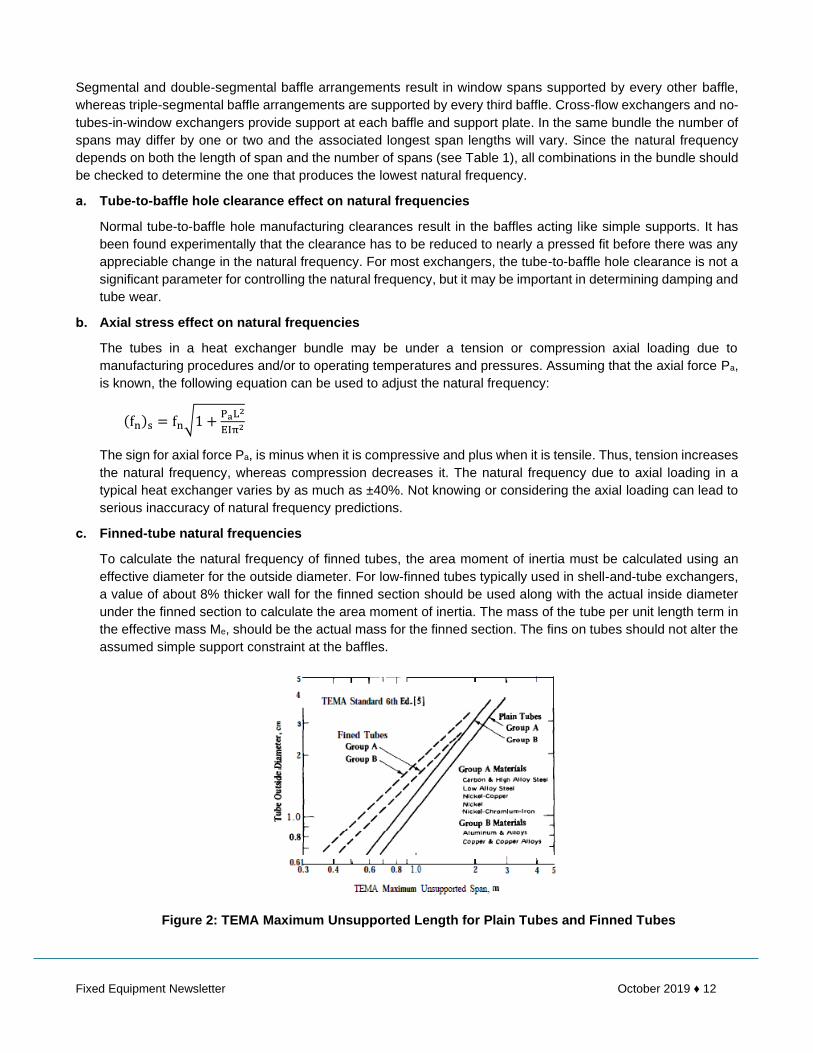
Figure 5 indicates that β is a function of the tube field layout. The effect of both tube field layout angle and tube
pitch-to-tube diameter ratio on β for banks of tubes is shown in Figure 6. These preliminary results also suggest
that as the pitch-to-diameter ratio decreases, the value of β decreases.
For the critical velocity method to be fully effective, it is necessary to predict the log decrement and the variation
of β with tube type, layout angle, and tube pitch.
PARALLEL-FLOW EDDY FORMATION
Vibration due to axial or parallel flow results from the development of eddies along the tube. Nuclear reactors, and
occasionally their associated heat exchangers, have experienced this type of vibration. Typically, they had long,

Fixed Equipment Newsletter October 2019 ♦ 17
unsupported tube spans, relatively narrow shell side flow passages, and very high axial velocities. The turbulent
eddy frequency is initiated by flow parallel to the tubes, which can excite the tubes into vibration at their natural
frequency. In most industrial shell-and-tube heat exchangers, axial-flow-induced vibration is not a problem, as the
axial flow in baffled exchangers is considerably below the critical velocity.
Figure 5: Stability Diagram for Tube Arrays
ACOUSTIC VIBRATION
Acoustic vibration occurs only when the shell-side fluid is a vapor or a gas. This type of vibration is related to
sound generated in an organ pipe. The characteristic frequency of the acoustic vibration in a heat exchanger
depends on some length, usually the shell diameter d, and the velocity of sound in the shell-side fluid usound. The
acoustic frequency fa, can be predicted by the following equation:
fa =musound
2d
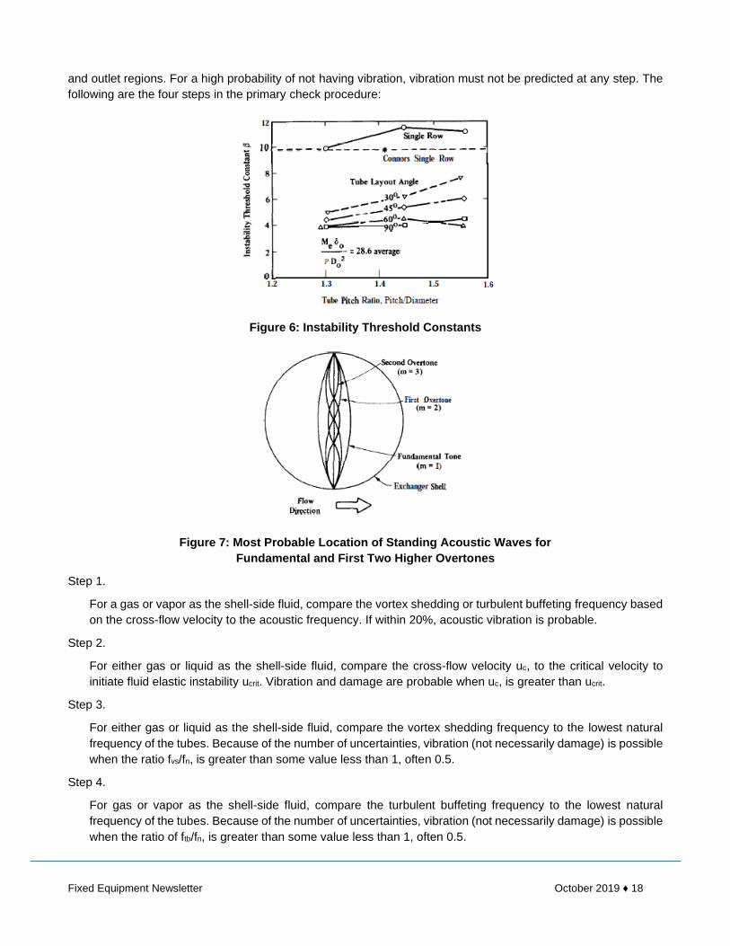
where m is the mode number, which is a dimensionless integer. The lowest acoustic frequency is achieved when
m = 1 and the characteristic length is the shell diameter. This is called the fundamental tone, and the higher
overtones vibrate at acoustic frequencies two, three, or four times the fundamental (m = 2, 3, or 4). The first two
overtones are illustrated in Figure 7. Reports of third, fourth, or higher overtones in heat exchangers are rare.
The acoustic frequencies of an exchanger can be excited by either vortex shedding or turbulent buffeting. So long
as the exciting frequencies are within 20% of an acoustic frequency, a loud noise may be produced. This acoustic
vibration becomes destructive when it is in resonance with some component of the exchanger. Good designs
ensure that the natural frequencies of the tubes differ from the acoustic frequencies of the exchanger shell. The
acoustic frequencies of the shell can be changed by inserting a detuning plate parallel to the direction of cross
flow to alter the characteristic length. This does not materially alter either the heat transfer or the pressure drop.
PROCEDURE FOR VIBRATION PREDICTIONS
PRIMARY CHECK
A four-step primary check is suggested for shell-and-tube heat exchanger designs to minimize the probability of
flow-induced vibration problems. The steps can be taken in any order and should be repeated for the inlet, central,
Fixed Equipment Newsletter October 2019 ♦ 18
and outlet regions. For a high probability of not having vibration, vibration must not be predicted at any step. The
following are the four steps in the primary check procedure:
Figure 6: Instability Threshold Constants
Figure 7: Most Probable Location of Standing Acoustic Waves for
Fundamental and First Two Higher Overtones
Step 1.
For a gas or vapor as the shell-side fluid, compare the vortex shedding or turbulent buffeting frequency based
on the cross-flow velocity to the acoustic frequency. If within 20%, acoustic vibration is probable.
Step 2.
For either gas or liquid as the shell-side fluid, compare the cross-flow velocity uc, to the critical velocity to
initiate fluid elastic instability ucrit. Vibration and damage are probable when uc, is greater than ucrit.
Step 3.
For either gas or liquid as the shell-side fluid, compare the vortex shedding frequency to the lowest natural
frequency of the tubes. Because of the number of uncertainties, vibration (not necessarily damage) is possible
when the ratio fvs/fn, is greater than some value less than 1, often 0.5.
Step 4.
For gas or vapor as the shell-side fluid, compare the turbulent buffeting frequency to the lowest natural
frequency of the tubes. Because of the number of uncertainties, vibration (not necessarily damage) is possible
when the ratio of ftb/fn, is greater than some value less than 1, often 0.5.

Fixed Equipment Newsletter October 2019 ♦ 19
Notice that the primary check procedure predicts the probability of vibration and not damage. Certainly, preventing
vibration from occurring precludes damage from vibration. On the other hand, the presence of vibration does not
automatically infer damage.
SECONDARY CHECK
The primary check procedure examines only the most obvious causes of tube vibration. There are additional
secondary checks that can be made. These include the velocities in the region of the inlet and outlet nozzles, high
values of the cross flow ρu2 , and the parallel-flow and cross-flow amplitudes. The leakage and bypass streams
can be checked to see if they are high and may lead to local vibration problems. A check can be made to ensure
that the acoustic frequency and tube natural frequencies are not in resonance.
VIBRATION DAMAGE RELATIONSHIP
Vibration cannot be equated to tube damage. Many exchangers vibrate but do not experience tube failure. Damage
is known to result from fatigue, tube-to-tube collision, and baffle-to-tube cutting. Fatigue is better understood than
the other two mechanisms. Tests that simulate the motion, forces, tube materials, and support materials, etc.,
found in real exchangers are needed to answer questions about low-amplitude (low-stress) vibration for a very
large number of cycles.
DESIGN CONSIDERATIONS
At the design phase there are a number of changes that can be made to reduce the vibration problem. Most require
a compromise to satisfy all of the requirements with added cost a likely result. When an exchanger already in
service has a serious problem, there are still some improvements that can be made in the field.
POSSIBLE DESIGN CHANGES TO CORRECT ANTICIPATED VIBRATION PROBLEMS
If, as the result of a vibration analysis, it is found that vibration is probable, design elements can be reconsidered
from the standpoint of vibration. Assuming that the process conditions cannot be changed, the following changes
should be considered:
Reduce the shell-side velocities
If the flow rate of the shell-side fluid is fixed, velocities can be reduced by increasing the tube pitch or using TEMA
X or J shell styles. This is particularly attractive when the design is pressure drop limiting, but may result in a larger
shell.
Increase the tube natural frequency
The most effective way to increase the tube natural frequency is to reduce the longest unsupported span length.
Reducing the span length by 8% increases the natural frequency by more than 5%. Secondary effects can be
produced by changing tube materials and increasing tube wall thickness, but neither of these will greatly increase
the natural frequency within industrially acceptable limits. The natural frequency can be increased by lacing or by
driving wedges between tubes to prevent movement. This technique has been particularly effective in controlling
vibration in the bend region of U-tube bundles.
Reduce nozzle velocities
The nozzle sizes can be increased to reduce nozzle velocities. If an impingement plate is provided to prevent
erosion, be sure that the velocities leaving the edges of the impingement plate are not excessively high. A support
plate at the centerline of the nozzles gives added tube support near the mid-span at the end zone. Annular
distributors and vapor belts are effective ways of reducing the velocity of the shell-side fluid entering the bundle.
Change baffle type
The no-tubes-in-window (NTIW) type bundle can have its baffles widely spaced, as every tube is supported by
every baffle. Further, the NTIW construction permits intermediate support plates between each baffle without
Fixed Equipment Newsletter October 2019 ♦ 20
materially affecting the heat transfer or pressure drop performance. A change to a multi-segmental baffle will
reduce the velocity. Although not common practice, the rod baffle type bundle has been used in low-pressure-drop
exchangers.
Add detuning baffles
Acoustic vibration problems can easily be corrected in the design phase by the use of detuning baffles to reduce
the characteristic length.
Reduce wear at baffles
Although the use of tighter tube-to-baffle clearance and thicker baffles do not materially change the tube natural
frequency, they do reduce damage due to cutting and increase the system damping. A change of baffle material
can sometimes reduce tube damage if originally the material was considerably harder than the tube material.
POSSIBLE SOLUTIONS FOR OBSERVED VIBRATION PROBLEMS
Once an operating heat exchanger is found to have a vibration problem, it should be determined if the vibration is
transmitted to the exchanger from some external source. If it is ascertained that the vibration is flow induced, there
are a number of possible solutions to be considered:
Plug leaking tubes
A temporary fix for leaking tubes, whatever the cause, is to drive plugs into the tube ends to seal off the leaking
tube. Replacing a tube in the field is generally not practical.
Reduce shell-side flow rate
Flow-induced vibration often can be stopped by lowering the shell-side flow rate. This will be acceptable only if it
can be tolerated within the operating requirements of the plant.
Insert bars, lacing, or wedges to stiffen the bundle
The natural frequencies of existing exchangers can be increased by inserting lacing or driving wedges between
the tubes to restrict movement. This can result in altered thermal and pressure drop performance. One region
where lacing and wedging is often used is in the U bend.
Remove tubes to create bypass lanes
This procedure can reduce the cross-flow velocities enough so that vibration can be controlled. However, this must
be done with care, as it can significantly reduce the overall heat transfer and pressure drop performance.
Replace the tube bundle
As a last resort, redesign and install a new bundle that circumvents the vibration problem.
Vibration problems are best prevented rather than corrected. A careful analysis at the design stage can greatly
reduce future vibration problems.
References:
Heat Exchanger Design Handbook – Spalding and Taborek

Fixed Equipment Newsletter October 2019 ♦ 21
RISK BASED INSPECTION (As applicable to pressure vessels and storage tanks)
Risk-Based Inspection (RBI) is an analysis methodology and process that, as opposed to condition-based
inspection, requires qualitative or quantitative assessment of the probability of failure (PoF) and the consequence
of failure (CoF) associated with each equipment item, piping circuits included, in a particular process unit. A
properly-implemented RBI program categorizes individual pieces of equipment by their risks and prioritizes
inspection efforts based on this categorization.
Probability of Failure
Probability of Failure (POF) is likelihood that a piece of equipment will fail at a given time and an important part of
effective risk analyses. POF is half of the equation when determining risk as part of Risk Based Inspection
(RBI) methodology. The POF, calculated together with the Consequence of Failure (COF), helps operators
establish the risk level for a particular piece of equipment and set inspection intervals based on the calculated
risk.
POF is calculated for individual pieces of equipment by looking at the potential damage mechanisms it could be
susceptible to, a general frequency of failures, and management system factors. More details on POF are
provided in the American Petroleum Institute's Recommended Practice 580 - Risk Based Inspection (RBI), which
contains directions on developing, implementing and maintaining an effective RBI program.
Consequence of Failure
Consequence of Failure (COF) is one part of the equation to determine risk as part of Risk Based Inspection
(RBI) methodology. COF is calculated by reviewing and ranking the potential consequences for the equipment,
personnel, environment, etc. in the event of equipment failure. The assessment shall consider all those
consequences that may take place as a result of fluid release. So the consequences that could be expected are:
▪ Fire
▪ Explosion
▪ Release of poisonous substances
▪ Health impacts
▪ Environmental impacts and pollution
More details on COF are given in API RP 580 - Risk Based Inspection (RBI), which contains directions on
developing, implementing and maintaining an effective RBI program.
WHY USE RBI?
RBI is used to identify and understand risk, risk drivers, and where equipment is in its lifecycle. RBI can indicate
whether inspection is needed; however this requires additional data that is extremely targeted to reduce the
underlying uncertainties associated with the risks about the current and future predicted damage state of the
equipment. RBI should not be used to recommend any inspection when it will not improve knowledge about the
damage state. In those cases, where PoF is driving the risk, RBI should point to other mitigation options such as
replacement, repair, or other actions that satisfy the risk criteria.
RBI can be used to prioritize inspection-related activities, usually by means of nondestructive testing (NDT), in
order to reduce the uncertainties around the true damage state of the equipment and the dynamics leading to
such. The resulting inspection plan may outline the type and scheduling of inspection for an asset. In addition to
NDE, additional risk mitigation activities identified by an RBI assessment might include a change in material of

Fixed Equipment Newsletter October 2019 ♦ 22
construction, installation of corrosion resistant liners, operating condition changes, injection of corrosion inhibition
chemicals, etc.
Consistency and repeatability of analysis are critical to producing an effective RBI program, as RBI is based on
relative risks. Caution should be used when mixing RBI platforms (e.g., using a qualitative method to perform the
initial screening and quantitative methods to conduct the final analysis). Complementary methodologies must be
calibrated against one another to ensure valid cut sets are achieved.
OVERVIEW OF RBI METHODOLOGY
RBI methodology uses equipment history and the likely consequences of equipment failure to determine
Inspection regimes focused on actual risks, so as to prevent unsafe incidents from occurring. The RBI method
adopted by most petroleum oil refineries is based on API 581 base resource document which involved
representatives from a number of major oil and petrochemical companies, and a comprehensive statistical analysis
of petrochemical facilities over a number of years. Due to the complexity of this RBI method, a computer-based
assessment is commonly used.
Each piece of equipment is assigned a risk ranking based on the probability and consequence of failure. Figure 1
shows a typical risk matrix. Red boxes (no. 1 to 5) indicate high risk. Pink boxes (no. 6 to 12) indicate medium-
high risk. Yellow boxes (no. 13-19) indicate medium risk. Green boxes (no. 20 to 25) indicate low risk.
Figure 1: Typical Risk Matrix
Based on this risk ranking, one can decide whether to:
▪ Remove equipment from service and conduct inspection (if equipment is showing high risk and there are
no suitable on-line inspection methods available that can help reduce the risk level).
▪ Apply appropriate on-line inspection methods for equipment to help reduce the risk level.
▪ Add to equipment inspection scope during turnaround to aid future risk assessments.
▪ Leave equipment on-line inspection and/or turnaround inspection scope at current level.
▪ Reduce equipment on-line inspection and/or turnaround inspection scope from current level.
A clear understanding of expected and possible damage mechanisms for equipment is required to conduct the
risk assessment and apply suitable inspection methods to mitigate risk posed by them. A consistent approach is
required for the reporting and assessment of damage mechanisms. API RP 571 provides valuable guidance in
identifying and understanding relevant damage mechanisms in process equipment.

Fixed Equipment Newsletter October 2019 ♦ 23
APPLICATION OF RBI TO CRUDE DISTILLATION COLUMN
Conducting RBI on a crude distillation column requires three basic processes:
1. Data collection and condition review
2. Criticality assessment and stakeholders input
3. Inspection planning and implementation
Data Collection and Condition Review
The RBI process begins by collecting accurate data on the equipment with regards to its process conditions,
operating parameters, design, construction & installation considerations, drawings, maintenance activities,
reliability, inspection history, modifications to the equipment/process, safety incidents, etc. The data collected is
usually entered into a RBI software application that facilitates the RBI process for ease of computation, data
management, inspection coordination and consistency between risk assessments.
Identifying the relevant damage mechanisms and their susceptible locations are particularly important for
managing the risk of equipment failure. For a physically large piece of equipment such as a crude distillation
column containing various process fluids, consideration is given to dividing the equipment into sub-components
for this exercise. The column is divided into three sections:
i. Top section - consisting of the top head and top section of the distillation column with light fractions;
ii. Middle section - representing a large portion of the distillation column’s cylindrical body containing medium
fractions;
iii. Bottom section - including the bottom head and bottom section of the distillation column with heavy
fractions.
Refer to Table 1 for damage mechanisms identified at these three sections.
Table 1: Damage Mechanisms in Crude Distillation Column, Measures for their Prevention/Mitigation and
Inspection/Monitoring
Column
Location
Damage
Mechanisms Prevention/Mitigation Inspection/Monitoring
Top
Ammonium Chloride Corrosion
Use Ni and Ti based alloys, but some may suffer pitting corrosion
Limit chlorides in tower feed through desalting and/or caustic addition to desalted crude
Flush salt deposits on overhead line with water wash
Control corrosion with filming amine inhibitors
Look for localized accumulation of ammonium chloride salts
Monitor thickness loss - RT, UT
Monitor ammonia and chlorides in feed streams
Look for drop in thermal performance and pressure drop of downstream heat exchangers
Use corrosion probes or coupons but deposits must be on them to work
HCl Corrosion
Reduce chloride in feed by optimizing crude oil tank water separation & withdrawal, and crude desalting operation
Upgrade carbon steel to Ni or Ti based alloys
Water wash to quench overhead stream and help dilute condensing HCl concentration
Inject caustic downstream of desalter to reduce amount of HCl going overhead. Use
Monitor general thinning on carbon steel, look for highly localized thinning where a water phase is condensing
Look for signs of serious corrosion at mix points where dry chloride containing streams mix with streams containing free water or where water saturated streams are cooled below the dew point

Fixed Equipment Newsletter October 2019 ♦ 24
proper design and operating methods to avoid caustic SCC and fouling in feed preheat train.
Inject various combinations of ammonia, neutralizing amines and filming amines in overhead line before water dew point.
Use UT scanning or profile RT to identify locally thinned areas
Use an effective process & corrosion monitoring program
Regularly check the water pH in the boot of overhead accumulator, also check chloride and iron content.
Use strategically placed corrosion probes/coupons
Middle
Sulfidation
Upgrade to higher chromium alloy
Use solid or clad 300 Series SS or 400 Series SS
Use aluminum diffusion treatment of low alloy steel components
Monitor process conditions for increasing temperatures and/or changing Sulphur levels
Use thermocouples and/or IR thermography to monitor temperature
Check for thic kness loss with UT and RT
Verify alloy used with PMI, prevent alloy mix-ups
Naphthenic Acid Corrosion (NAC)
Change or blend crudes, upgrade metallurgy, utilize chemical inhibitors.
Use alloys with higher molybdenum content, 317L SS
Use high temperature NAC inhibitors
Use RT as primary detection method for localized erosion, followed by UT
Monitor Total Acid Number (TAN) and Sulphur content of crude change and side streams
Use corrosion probes/coupons, H2 probes
Monitor streams for Fe and Ni content
Erosion/ Erosion- Corrosion (E/EC)
Improve design on shape, geometry and materials selection
Increasing substrate hardness using harder alloys or surface-hardening treatments
Use corrosion-resistant alloys , alter process environment
Visual inspection, UT or RT - look for troublesome areas and detect thickness loss
Specialized corrosion coupons, on-line corrosion monitoring electrical resistance probes
On-line IR scans
Chloride Stress Corrosion Cracking (Cl SCC)
Use resistant materials, properly apply coatings under insulation and design out stagnant regions to avoid chloride accumulation. High temperature stress relief 300 Series SS after fabrication considering the effects of sensitization.
Hydrotest with low chloride content water, rinse & dry out thoroughly and quickly.
Visual inspection, PT, UT, phase analysis EC techniques
For PT, may need polishing or high-pressure water blast
RT may not be sufficiently sensitive to detect cracks except in advanced stages (network of cracks)
Bottom
Sulfidation Refer to ”Sulfidation” above Refer to ”Sulfidation” above
NAC Refer to ”NAC” above Refer to ”NAC” above
E/EC Refer to ”E/EC” above Refer to ”E/EC” above
CI SCC Refer to “Cl SCC” above Refer to “Cl SCC” above
885F (475C) embrittlement
Use low ferrite or non-ferritic alloys or avoid material exposure to embrittling range
Reverse embrittlement by heat treating to 1100°F followed by rapid cooling(1)
Impact or bend test sample removed from service
Look for cracking formed during turnarounds, startup or shutdown when material is below ~200°F

Fixed Equipment Newsletter October 2019 ♦ 25
Check for increase in hardness
Note: (1) If the de-embrittled component is exposed to the same service conditions it will re-embrittle faster than it did initially.
Reviewing the data collected before using them for the criticality assessment underpins an accurate outcome;
after all, there is a saying of “garbage in, garbage out”. The RBI analyst should review the equipment inspection
history being mindful of the relevant damage mechanisms, their effects on the equipment and effectiveness of
inspections done in the past. Communication with stakeholders such as production, engineering, maintenance
and inspection personnel is necessary to form a complete picture about the equipment and gain insight about it
that is not often readily documented.
Equipment data and information relevant to the risk assessment are entered into the RBI software application
before criticality assessment. A simple calculation of corrosion rates (e.g. external and internal) is often required
and their entry into the RBI application should be accompanied by a clear explanation of their basis.
Criticality Assessment and Stakeholders Input
Criticality can be assessed for each three sections of the crude distillation column using section-specific
information to determine the consequence and probability of failure. The consequence of failure usually considers
flammability, toxicity and production loss, while the probability of failure usually considers the effects of internal &
external corrosion, environmental cracking and other damage mechanisms. Other considerations for consequence
and probability may be included depending on the configuration of RBI software application and user requirements.
For the criticality analysis on each column section, a risk level can be evaluated for the section’s current state and
risk levels can be evaluated for the section’s future states, depending on the number of equipment run length
intervals being considered, or the level of conservatism used in the criticality analysis (e.g. Comparing risk using
a more severe corrosion rate versus a less severe corrosion rate to reflect various repair or operating strategies).
Figure 2 shows a typical criticality assessment for the top head of a crude distillation column.
Figure 2: Typical Critical Assessment for the Top Head of Crude Distillation Column
(Courtesy: Capstone RBMI, an RBI Software Application)
Stakeholders input from operations, engineering, environmental, safety and maintenance departments may be
required to accurately reflect the consequence of failure. The RBI analyst must carefully interpret inspection
records and seek input from experienced inspectors when addressing the probability of failure. A range of
personnel are involved in equipment integrity assurance and reliability maintenance, effectively using the input
from various stakeholders will help produce accurate criticality outputs for the equipment’s current and future
states.

Fixed Equipment Newsletter October 2019 ♦ 26
Inspection Planning and Implementation
An inspection plan is developed based on the criticality evaluated in the current state and future states of the crude
distillation column for its three sections, and the acceptable level of risk. For example, following equipment
turnaround with an effective inspection scope (and repairs if required), one would not expect the equipment to still
show high criticality. If a high criticality is evaluated for its future state depending on its run length, design,
inspection history, relevant damage mechanisms, environment, operating & process conditions, and consequence
parameters, then one or a combination of these must be addressed in order to reduce the criticality to a more
acceptable level (e.g. medium or low).
For a crude distillation column, the inspection and monitoring measures presented in Table 1 should be included
in the inspection plan along with regular on-line visual external inspection. The inspection scrutiny for each type
of damage mechanism should be matched with the equipment history, as well as process and operating conditions.
APPLICATION OF RBI TO CRUDE STORAGE TANK
Application of RBI to a crude storage tank follows a similar process to the crude distillation column with the
following exceptions:
Data Collection and Condition Review
The tank is divided into three sections:
1. Bottom - consisting of the annular plates and floor island plates. Sometimes, these are divided into two
sub-sections for analysis;
2. Shell - the tank shell strakes; and
3. Roof - the roof plates.
Relevant damage mechanisms are:
▪ HCl Corrosion - related to crude heating
▪ Mechanical Fatigue - at shell corner joint with regular tank filling and emptying
▪ Atmospheric Corrosion - tank external components
▪ Corrosion under Insulation - for insulated crude tanks with heavy crude
▪ Microbiologically induced Corrosion - crude with hydrocarbon contaminants and water present
▪ Soil Corrosion - underside of tank bottom
Criticality Assessment and Stakeholders Input
Criticalities are assessed for the tank bottom, shell and roof representing the equipment’s current state and future states.
Inspection Planning and Implementation
An inspection plan is developed based on the criticalities evaluated in the current state and future states of the
tank for its three sections, and the acceptable level of risk. Implementing this plan and re-assessing this plan is
crucial to keeping the risk ALARP (as low as reasonably possible).
CODES AND STANDARDS
International engineering standards and practices that relate to risk-based inspection include, but are not limited
to, API RP 580 and 581, ASME PCC-3, and RIMAP. API RP 580 sets out the minimum guidelines for implementing
an effective, credible RBI program. API RP 581 details the procedures and methodology of RBI.

Fixed Equipment Newsletter October 2019 ♦ 27
CONCLUSIONS
With RBI, the equipment risk is managed by:
▪ Understanding the failure mechanism, susceptible locations, analyzing the risk of subcomponents, identify
and address the highest risk, planning inspection and addressing the risk with stakeholders to prevent all
undesired failures.
▪ Monitoring process variables and recognizing changes in the process such as upset conditions, change
in process composition and operating limits. A management of change system is required.
▪ Knowing the level of inspection confidence (data representative of equipment’s true condition and location)
and inspection quality. Inspection confidence reflects how accurately inspection data represents the true
condition of equipment, it relates to the damage type identified, inspection method used for its detection
and location inspected. Inspection quality reflects the repeatability of the inspection process in terms of
equipment access, instruments, operator, environment and process.
When applied and implemented properly, value is obtained from RBI by reducing equipment risk and cost.
References:
Application of Risk Based Inspection to Pressure Vessels and Aboveground Storage Tanks in Petroleum Fuel
Refineries – Jenny Simpson
Overview of Risk Based Inspection - Inspectioneering

Fixed Equipment Newsletter October 2019 ♦ 28
This page left intentionally blank.

Fixed Equipment Newsletter October 2019 ♦ 29
TROUBLE SHOOTING LEAKING JOINTS
One of the best available tools to aid in determining the cause of leakage is a careful examination of the gasket
in use when leakage occurred.
OBSERVATION POSSIBLE REMEDIES
Gasket badly corroded. Select replacement material with improved
corrosion resistance.
Gasket extruded excessively.
Select replacement material with better cold flow
properties, select material replacement with
better load bearing capability - I.e., more dense.
Gasket grossly crushed.
Select material replacement with better load
bearing capability, provide means to prevent
crushing the gasket by use of a stop ring or re-
design of flanges.
Gasket mechanically damaged due to overhang
of raised face or flanged bore.
Review gasket dimensions to ensure gaskets are
proper size. Make certain gaskets are properly
centered in joint.
No apparent gasket compression achieved.
Select softer gasket material. Select thicker
gasket material. Reduce gasket area to allow
higher unit seating load.
Gasket substantially thinner on OD than ID.
Indicative of excessive "flange rotation' or
bending. Alter gasket dimensions to move gasket
reaction closer to bolts to minimize bending
moment. Provide stiffness to flange by means of
back-up rings. Select softer gasket material to
lower required seating stresses. Reduce gasket
area to lower seating stresses.
Gasket unevenly compressed around
circumference.
Improper bolting up procedures followed. Make
certain proper sequential bolt up procedures are
followed.
Gasket thickness varies periodically around
circumference.
Indicative of flange "bridging" between bolts or
warped flanges. Provide reinforcing rings for
flanges to better distribute bolt load. Select
gasket material with lower seating stress.
Provide additional bolts, if possible, to obtain
better load distribution. If flanges are warped, re-
machine or use softer gasket material.
References:
ASME Boiler and Pressure Vessel Code, Section VIII, Division 1 – 2019 Edition

BUILDING A BETTER TOMMORROW
It is becoming less practical for many
companies to maintain in-house
engineering staff. That is where we
come in – whenever you need us,
either for one-time projects, or for
recurring engineering services. We
understand the codes and standards,
and can offer a range of services
related to pressure vessels, tanks and
heat exchangers.
Training & Development
Engineering and Design Services
CoDesign
Engineering
Pressure Vessels ● Heat Exchangers ● Storage Tanks
Oil & Gas ● Petrochemical ● Chemical ● Power ● Fertilizer