Embed Size (px)
Citation preview

SECOND FIVE‐YEAR REVIEW Sprague Road Groundwater Plume Superfund Site
EPA ID# TX0001407444 Odessa, Ector County, Texas
This memorandum documents the U.S. Environmental Protection Agency’s (EPA’s) performance, determinations, and approval of the Sprague Road Groundwater Plume Superfund Site (Site) second five‐year review under Section 121(c) of the Comprehensive Environmental Response, Compensation & Liability Act (CERCLA), 42 United States Code (USC) §9621, et seq. as provided in the attached second five‐year review report.
Summary of Second Five‐Year Review Findings
The remedy was implemented to prevent further migration of a chromium plume in the Trinity aquifer and restore the aquifer to its beneficial uses. The groundwater remediation system at the Site consists of an extraction well system, a treatment system, and an injection system for the return of treated water to the aquifer. The treatment system operated as intended by the 2000 Record of Decision (ROD) until December 12, 2010. The ion exchange treatment system, which was installed during construction in 2002‐2003, was shut down for contractual reasons. After performing multiple bench‐scale tests and pilot studies, an ultraviolet light‐activated slurry catalyst system (Photo‐Cat system) was selected to replace the ion exchange water treatment system. The Photo‐Cat was delivered in March 2013, and start‐up and shake‐down operations are underway.
Site interviews were not conducted during this five‐year review site visit. Due to the system being nonoperational at the time of the visit, site interviews and an evaluation of the new groundwater treatment system have been postponed to a later date. The responses from interviews and information related to the new treatment system will be presented in a Five‐Year Review Report Addendum that will be prepared in the next 12 to 18 months.
The second five‐year review focused on the data obtained during routine operation and maintenance of the system and groundwater monitoring events conducted at the Site during 2008 through 2013. At this time, issues noted during this five‐year review include the following:
1. Groundwater plume migration—The groundwater data and model indicate that the plumes at all three release areas (Machine & Casting, Leigh Metal (LM), and National Chromium Corporation (NCC)) have migrated downgradient.
2. Fence damage—The northwest corner of the LM facility has minor fence damage.
3. Well maintenance—The condition of the recovery and injection wells has deteriorated during the time the treatment system has been down. Standing water was observed in some of the well vaults; some piping and vaults were rusty; electric junction boxes in the vaults were open and contained water, rust, and dirt; well caps were not in place on many of the wells; some of the concrete pads were cracked or damaged; and some of the electrical wires were loose or corroded. Additionally, some of the monitoring wells need minor repairs.
4. Vertical contaminant migration—Concentrations above and below the clay lens in the NCC nested monitoring wells and water supply wells indicate possible vertical migration of contaminants.
5. Institutional Controls—Appropriate institutional controls to prevent the installation of water supply wells in or downgradient of the contaminant plumes have not been implemented.
6. Vadose zone flushing system—The vadose zone flushing system installed based on the remedy selected in the Record of Decision has never been operated.
SPRAGUE-2NDFYR_COVERMEMO REV 1
SPRAGUE ROAD GROUNDWATER PLUME SUPERFUNO SITE SECOND FIVE-YEAR REVIEW REPORT
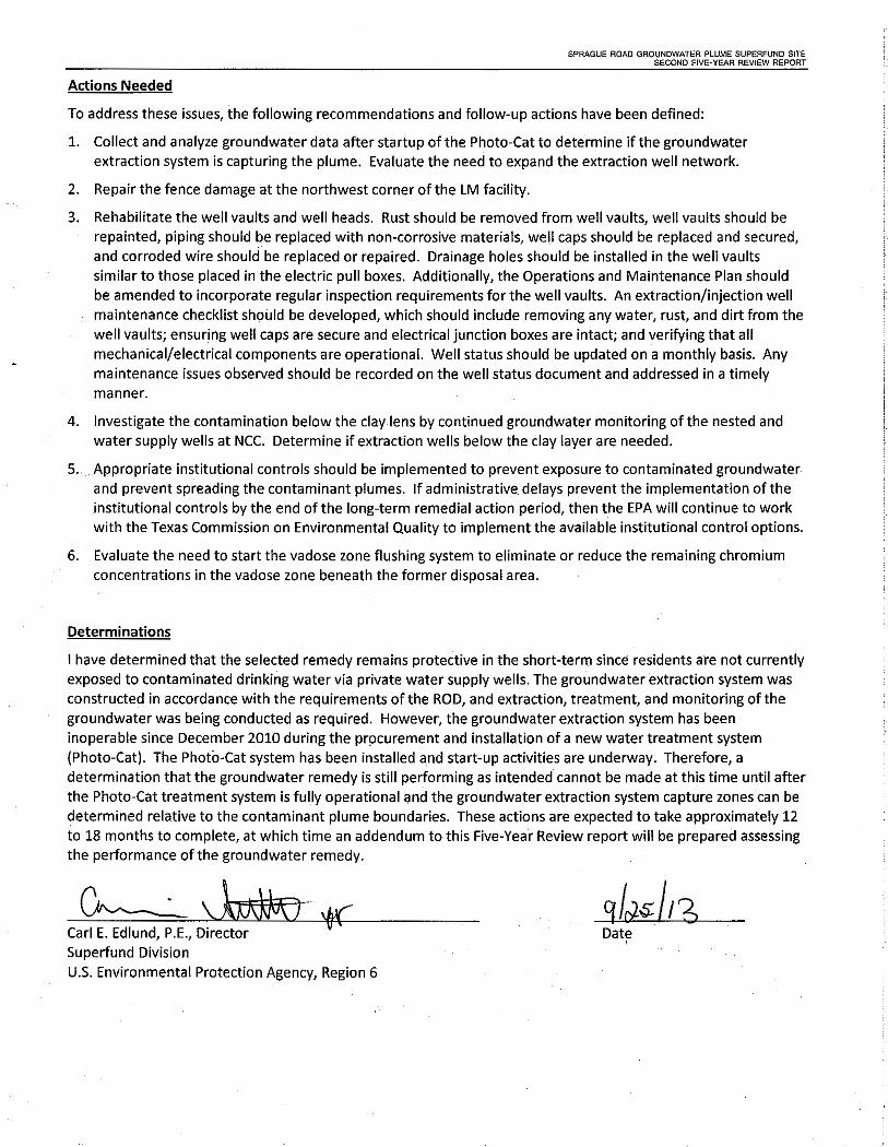
Actions Needed
To address these issues, the following recommendations and follow-up actions have been defined:
1. Collect and analyze groundwater data after startup of the Photo-Cat to determine if the groundwater extraction system is capturing the plume. Evaluate the need to expand the extraction well network.
2. Repair the fence damage at the northwest corner of the LM facility.
3. Rehabilitate the well vaults and well heads. Rust should be removed from well vaults, well vaults should be repainted, piping should be replaced with non-corrosive materials, well caps should be replaced and secured, and corroded wire should be replaced or repaired. Drainage holes should be installed in the well vaults similar to those placed in the electric pull boxes. Additionally, the Operations and Maintenance Plan should be amended to incorporate regular inspection requirements for the well vaults. An extraction/injection well maintenance checklist should be developed, which should include removing any water, rust, and dirt from the well vaults; ensuring well caps are secure and electrical junction boxes are intact; and verifying that all mechanical/electrical components are operational. Well status should be updated on a monthly basis. Any maintenance issues observed should be recorded on the well status document and addressed in a timely manner.
4. Investigate the contamination below the clay lens by continued groundwater monitoring of the nested and water supply wells at NCC. Determine if extraction wells below the clay layer are needed.
5. Appropriate institutional controls should be implemented to prevent exposure to contaminated groundwater and prevent spreading the contaminant plumes. If administrative delays prevent the implementation of the institutional controls by the end of the long-term remedial action period, then the EPA will continue to work with the Texas Commission on Environmental Quality to implement the available institutional control options.
6. Evaluate the need to start the vadose zone flushing system to eliminate or reduce the remaining chromium concentrations in the vadose zone beneath the former disposal area.
Determinations
I have determined that the selected remedy remains protective in the short-term since residents are not currently exposed to contaminated drinking water via private water supply wells. The groundwater extraction system was constructed in accordance with the requirements of the ROD, and extraction, treatment, and monitoring of the groundwater was being conducted as required. However, the groundwater extraction system has been inoperable since December 2010 during the pr9curement and installation of a new water treatment system (Photo-Cat). The Photo-Cat system has been installed a.nd start-up activities are underway. Therefore, a determination that the groundwater remedy is still performing as intended cannot be made at this time until after the Photo-Cat treatment system is fully operational and the groundwater extraction system capture zones can be determined relative to the contaminant plume boundaries. These actions are expected to take approximately 12 to 18 months to complete, at which time an addendum to this Five-Year Review report will be prepared assessing the performance of the groundwater remedy.
Carl E. Edlund, P.E., Director Date ' Superfund Division
U.S. Environmental Protection Agency, Region 6

------------------
f'R~uting and Concurrence Slip ______ - - H I B~gin Routing Date:I09/05/2013 m . rn
1;_---~-1> -- ---· -- ---···-- -- ----·· -- -
[fo: (Name, office symbol, route number, building, Agency/Post I ln_itials I Date l"';~,~~~--c~-A-n-n"'e~F-o-s-te~r---~--'---'---'---'-=-c=-~--'-~--~I c-.---c~A-_F"'.·-'--'-~I. 09/05/2013
09/06/2013ljj.,_-.,~ - '-Carlos Sanchez-----~-~-------~----·-_c_s_-_---~1·' •:@l - .
I 09/06/2013lifijj ~ohn Mey~~;~-Carlos Sanchez I. CS
CF 09/11/2013
09/17/2013t _t::::;::~ _,___ ,____,_~_,_.·.----"--''·-~-J MP I
,.,, ~stei:>ll~nie Delgado ''_L_______J_..i_•~------·___.JC i~li~ill ,_ -J I~-i~~
r- -- ·- - --------- -- - - ---litiK~:;_¢~,:,)0/~.>'>iiJ:.:,___,:,.>~- __t,;, ""''·--· ----- ,,_,,_ ,, -·""--- '"'---··· 1.;;,,;, ,.,.,__,._,,,__;;_;;,,,,_,"-<;,,,,,_,,,2,1_;;,__,,_y_-'-''--'-'-'-''··-'-'•·'-'-'2-•.. _,,, ,, _
Offic:j D Remedial Branch - Arkansas/Texas Section 1
I' "'-·-_. "'~rackin~-~~~egory:jj~0·_-_F_i_ve_-_Y_e_a_r_R_ev_i_ew_·~~-~-----'-~-------------!• ·Enforc!ment Confidential:! 0,
7
Y_11s _e _lll_c>________________________ _
1;- · Email Subject:] SP@llL!eRoad_~[ld Five"YearReview Rep0rt
I'• __ _ __D11_e_[)afl):]109/13/2013 [ _DD/DDD Assigned:] 1---- ------- DD/DDD Status:! Pending
DD/DDD Remarksj ,_,___ Front Office Assigned_:]_
l,g.ciJ~~;'~0 '"'''"'""-"''.. '"·0·~~.;·rd~~i.;; '""'~'-'-'[]_Ju~;;1y''"'•"''''"''"''~'''"'''o~sig,~al~~~ -- """' ·-'•-'-'&••'''·-=-- ·------ ''"'1
11 ·.. . .. !--D Approval D File DNote andReturn DAD Signature l''DAs Requested D For Clearance · D Per Conversation D DD/DDD Signature liO Circulate D For Correction DPrepare Reply D RA Signature l:D Comment D For Your Information D Review I i;xJ Co_n_cljrrence D Investigation _ D See Me !~Remarks: I Briefing with DD/DDD on report completed on August 29,. 2013 l1'rom: (Name, org, symbol, Agency/Post) ----- - - I Room No:18-1ci9J6s_F_-_R_~--IVincent Malott ___ _______ _ ..... ________ L. _f'~()n_e Number:i_2_1__4,665.8313
Cl!Qose EDITdocument ;ind.turn onTrackch;ingesJnWORD. . -Rell'leml:>E!r tc>S.AVE'tlle Word [)ocu'rriellt l:>et<>re e~iifng Word...,... -
ll-.iilil~.c;lJ52l~'-~ljj_~El~~JA~~i1J~i~ii1\iJ;,f!Jiril~~:itY~ll~~¥l~~[1a ·fl~~~;, :~iii....~±fo+Yi~

SPRAGUE ROAD GROUNDWATER PLUME SUPERFUND SITE SECOND FIVE-YEAR REVIEW REPORT
This page intentionally left blank.
SPRAGUE-2NDFYR_COVERMEMO 4

Second Five‐Year Review Report
Sprague Road Groundwater Plume Superfund Site
Odessa, Ector County, Texas
August 2013
Superfund Division
U.S. Environmental Protection Agency
Region 6
Dallas, Texas

SPRAGUE ROAD GROUNDWATER PLUME SUPERFUND SITE SECOND FIVE-YEAR REVIEW REPORT
This page is intentionally left blank.

Executive Summary The U.S. Environmental Protection Agency (EPA) Region 6 has conducted the second five‐year review of the remedial action (RA) implemented at the Sprague Road Groundwater Plume Superfund Site, hereafter referred to as “the Site,” in Ector County, Texas. The purpose of this second five‐year review was to determine whether the selected remedy for the Site continues to protect human health and the environment. This review was conducted from October 2012 to June 2013 and its findings and conclusions are documented in this report. RA construction activities were completed in September 2003 and the First Five‐Year Review Report was completed in September 2008; this established the second five‐year review period of 2008 to 2013.
The Site consists of three abandoned metal plating facilities located within one mile of each other. Electroplating activities at these facilities, including the repair and reconditioning of oil field equipment, generated sludge and chromic acid rinse water. The past operations and waste disposal practices at each of the three facilities have resulted in the release of chromium to the groundwater (EA 2012b).
The Leigh Metal (LM) facility is approximately 3.6 acres in size and is located near the intersection of Sprague Road and 81st Street (Figure 1). The LM facility consists of an abandoned main office/machine shop building and a second building that contained a chrome plating shop. The facility operated from 1976 to 1992, and chromium acid was released from two plating tanks inside the plating shop (EA 2012b).
The National Chromium Corporation (NCC) facility is approximately 2.5 acres in size and is located near the intersection of Sprague Road and Steven Road (Figure 1). The NCC facility consists of an abandoned main office/machine shop, approximately 850 feet south of the LM facility. The facility operated from 1979 to 1993, and chromic acid waste was disposed of in a 20,000 gallon evaporation pond (EA 2012b).
The Machine and Casting (M&C) facility is approximately 2 acres in size and is located near Sprague Road and Hillmont Road (Figure 1). The M&C facility consists of an abandoned office/machine shop building, approximately 1,500 feet north of the LM facility. The facility operated from 1978 to 1988, and chromic acid waste was released from a sump located beneath a former plating room (EA 2012b).
The groundwater beneath all three facilities has been impacted by chromium in excess of the drinking water standard maximum contaminant level (MCL) (100 micrograms per liter [µg/L] total chromium) (EA 2012b).
The Site was listed on the National Priorities List (NPL) in 1997 (EPA 2013a). The EPA signed the record of decision (ROD) for the Site on 29 September 2000. The remedial action objectives (RAOs), selected remedy, and implementation status are discussed in the following paragraphs.
The RAOs were as follows:
Prevent exposure to contaminated groundwater, above acceptable risk levels
Prevent or minimize further migration of the groundwater contaminant plume
Prevent or minimize further migration of contaminants from source materials to groundwater
I

EXECUTIVE SUMMARY
Return groundwaters to their expected beneficial uses wherever practicabl
The selected remedy consisted of the following:
Installation of groundwater extraction wells at each contaminant plume to maximize contaminant reduction and prevent further migration of the plume.
Treatment of the contaminated groundwater utilizing one of the presumptive remedies described in the Presumptive Response Strategy and Ex‐Situ Treatment Technologies for Contaminated Groundwater at Comprehensive Environmental Response, Compensation, and Liability Act (CERCLA) Sites (Office of Solid Waste and Emergency Response (OSWER) Directive 9283.1‐12, October 1996). Wastes generated during the treatment process would be transported to an off‐site location for disposal in accordance with Resource Conservation and Recovery Act (RCRA) and CERCLA requirements.
The re‐injection of the treated water into the aquifer utilizing one or a combination of the following: injection wells, dry wells, and/or infiltration galleries.
The use of infiltration galleries or other means to flush the hexavalent chromium from the vadose zone to levels that will ensure the area does not act as a potential source of contamination or prevent the restoration of the groundwater under future land‐use scenarios.
Long‐term groundwater monitoring to evaluate the effectiveness of the groundwater extraction and disposal system and ensure there is no further exposure to contaminated groundwater above the applicable drinking standards.
Construction began in October 2002 and was completed in August 2003. The EPA prepared a preliminary closeout report in September 2003. The remedy was determined to be Operational and Functional (O&F) in September 2004. Long‐Term Response Action (LTRA) activities, including operation and maintenance of the system and groundwater monitoring, began on September 30, 2004. The groundwater extraction, treatment, and reinjection system operated as intended by the decision documents until December 12, 2010. The ion exchange system (remedy) was shut down for contractual reasons. After performing multiple bench‐scale tests and pilot studies, an ultraviolet light‐activated slurry catalyst system (Photo‐Cat system) was selected to replace the ion exchange water treatment system. Complications were encountered during the development of the Photo‐Cat system which delayed delivery until March 1, 2013. The Photo‐Cat has been installed and start‐up and shake‐down operations are underway.
The five‐year review for the Site included a review of relevant documents, including the ROD, Final Design Report, RA Report, Operation and Maintenance Plan, Operating Reports, Groundwater Monitoring Reports, In situ Pilot Test Report, Photo‐Cat Pilot Test Summary Report.
Site interviews were not conducted during this five‐year review site visit. Due to the system being nonoperational at the time of the visit, site interviews and an evaluation of the new groundwater treatment system have been postponed to a later date. The responses from interviews and information related to the new treatment system will be presented in a Five‐Year Review Report Addendum that will be prepared in the next 12 to 18 months.
II

EXECUTIVE SUMMARY
The second five‐year review focused on the data obtained during routine operation and maintenance of the system and groundwater monitoring events conducted at the Site during 2008 through 2013. At this time, issues noted during this five‐year review include the following:
1. Groundwater plume migration—The groundwater data and model indicate that the plumes at all three release areas (M&C, LM, and NCC) have migrated downgradient.
2. Fence damage—The northwest corner of the LM facility has minor fence damage.
3. Well maintenance—The condition of the recovery and injection wells has deteriorated during the time the treatment system has been down. Standing water was observed in some of the well vaults; pipe and vaults were rusty; electric junction boxes in the vaults were open and contained water, rust, and dirt; well caps were not in place on many of the wells; some of the concrete pads were cracked or damaged; and some of the electrical wires were loose or corroded. Additionally, some of the monitoring wells needed minor repairs.
4. Vertical contaminant migration—Concentrations above and below the clay lens in the NCC nested monitoring wells and water supply wells indicate possible vertical migration of contaminants.
5. Institutional Controls—Appropriate institutional controls to prevent the installation of water supply wells in or downgradient of the contaminant plumes have not been implemented.
6. Vadose zone flushing system—The vadose zone flushing system installed based on the remedy selected in the ROD has never been operated.
Recommended follow up actions are:
1. Collect and analyze groundwater data after startup of the Photo‐Cat to determine if the groundwater extraction system is capturing the plume. Evaluate the need to expand the extraction well network.
2. Repair the fence damage at the northwest corner of the LM facility.
3. Rehabilitate the well vaults and well heads. Rust should be removed from well vaults and they should be repainted, piping should be replaced with non‐corrosive materials, well caps should be replaced and secured, and corroded wire should be replaced or repaired. Drainage holes should be installed in the well vaults similar to those placed in the electric pull boxes. Additionally, the Operations and Maintenance Plan should be amended to incorporate regular inspection requirements for the well vaults. An extraction/injection well maintenance checklist should be developed, which should include removing any water, rust, and dirt from the well vaults; ensuring well caps are secure and that the electrical junction boxes are intact; and verifying that all mechanical/electrical components are operational. Well status should be updated on a monthly basis. Any maintenance issues observed should be recorded on the well status document and addressed in a timely manner.
4. Investigate the contamination below the clay lens by continued groundwater monitoring of the nested and water supply wells at NCC. Determine if extraction wells below the clay layer are needed.
III

EXECUTIVE SUMMARY
5. Appropriate institutional controls should be implemented to prevent exposure to contaminated groundwater and prevent spreading the contaminant plumes. If administrative delays prevent the implementation of the institutional controls by the end of the LTRA period, then the EPA will continue to work with the Texas Commission on Environmental Quality to implement the available institutional control options.
6. Evaluate the need to start the vadose zone flushing system to eliminate or reduce the remaining chromium concentrations in the vadose zone beneath the former disposal area.
IV

Issues/Recommendations
Five-Year Review Summary Form SITE IDENTIFICATION
Site Name: Sprague Road Groundwater Plume Superfund Site
EPA ID: TX0001407444
Region: 6 State: Texas City/County: Odessa/Ector County
SITE STATUS
NPL Status: Final
Multiple OUs? Has the site achieved construction completion?
No Yes
REVIEW STATUS
Lead agency: EPA If “Other Federal Agency” was selected above, enter Agency name:
Author name (Federal or State Project Manager): Vince Malott
Author affiliation: EPA
Review period: October 2012 – June 2013
Date of site inspection: May 20–22, 2013
Type of review: Policy
Review number: 2
Triggering action date: September 29, 2008
Due date (five years after triggering action date): September 29, 2013
OU(s) without Issues/Recommendations Identified in the Five-Year Review:
None.
Issues and Recommendations Identified in the Five-Year Review:
OU(s): Site Issue Category: Remedy Performance
Issue: Groundwater plume migration—The groundwater data and model indicate that the plumes at all three release areas (M&C, LM, and NCC) have migrated downgradient.
V

Five-Year Review Summary Form (continued) Recommendation: Collect and analyze groundwater data after startup of the Photo-Cat to determine if the groundwater extraction system is capturing the plume. Evaluate the need to expand the extraction well network.
Affect Current Protectiveness
Affect Future Protectiveness
Implementing Party
Oversight Party
Milestone Date
No Yes EPA State September 2014
OU(s): Site Issue Category: Site Access/Security
Issue: Fence damage—the northwest corner of the LM facility has minor fence damage.
Recommendation: Repair the fence damage at the northwest corner of the LM facility.
Affect Current Protectiveness
Affect Future Protectiveness
Implementing Party
Oversight Party
Milestone Date
No No EPA State September 2013
OU(s): Site Issue Category: Operations and Maintenance
Issue: Well maintenance—The condition of the recovery and injection wells has deteriorated during the time the treatment system has been down. Standing water was observed in some of the well vaults; pipe and vaults were rusty; the electric junction boxes in the vaults were open and contained water, rust, and dirt; well caps were not in place on many of the wells; some of the concrete pads were cracked or damaged; and some of the electrical wires were loose or corroded. Additionally, some of the monitoring wells needed minor repairs.
Recommendation: Rehabilitate the well vaults and well heads. Rust should be removed from well vaults and they should be repainted, piping should be replaced with non-corrosive materials to prevent adverse impact to the Photo-Cat treatment system, well caps should be replaced and secured, and corroded wire should be replaced or repaired. Drainage holes should be installed in the well vaults similar to those placed in the electric pull boxes. Additionally, the Operations and Maintenance Plan should be amended to incorporate regular inspection requirements for the well vaults. An extraction/injection well maintenance checklist should be developed, which should include removing any water, rust, and dirt from the well vaults; ensuring well caps are secure and that the electrical junction boxes are intact; and verifying that all mechanical/electrical components are operational. Well status should be updated on a monthly basis. Any maintenance issues observed should be recorded on the well status document and addressed in a timely manner.
Affect Current Protectiveness
Affect Future Protectiveness
Implementing Party
Oversight Party
Milestone Date
No Yes EPA State Ongoing
VI
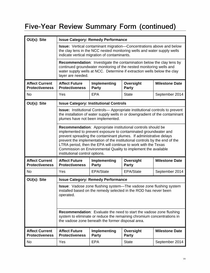
Five-Year Review Summary Form (continued) OU(s): Site Issue Category: Remedy Performance
Issue: Vertical contaminant migration—Concentrations above and below the clay lens in the NCC nested monitoring wells and water supply wells indicate vertical migration of contaminants.
Recommendation: Investigate the contamination below the clay lens by continued groundwater monitoring of the nested monitoring wells and water supply wells at NCC. Determine if extraction wells below the clay layer are needed.
Affect Current Protectiveness
Affect Future Protectiveness
Implementing Party
Oversight Party
Milestone Date
No Yes EPA State September 2014
OU(s): Site Issue Category: Institutional Controls
Issue: Institutional Controls— Appropriate institutional controls to prevent the installation of water supply wells in or downgradient of the contaminant plumes have not been implemented.
Recommendation: Appropriate institutional controls should be implemented to prevent exposure to contaminated groundwater and prevent spreading the contaminant plumes. If administrative delays prevent the implementation of the institutional controls by the end of the LTRA period, then the EPA will continue to work with the Texas Commission on Environmental Quality to implement the available institutional control options.
Affect Current Protectiveness
Affect Future Protectiveness
Implementing Party
Oversight Party
Milestone Date
No Yes EPA/State EPA/State September 2014
OU(s): Site Issue Category: Remedy Performance
Issue: Vadose zone flushing system—The vadose zone flushing system installed based on the remedy selected in the ROD has never been operated.
Recommendation: Evaluate the need to start the vadose zone flushing system to eliminate or reduce the remaining chromium concentrations in the vadose zone beneath the former disposal area.
Affect Current Protectiveness
Affect Future Protectiveness
Implementing Party
Oversight Party
Milestone Date
No Yes EPA State September 2014
VII

Five-Year Review Summary Form (continued) Protectiveness Statement(s)
Operable Unit: Site
Protectiveness Determination: Protective
Addendum Due Date (if applicable): Not Applicable
Protectiveness Statement: See Sitewide Protectiveness Statement
Sitewide Protectiveness Statement (if applicable)
Protectiveness Determination: Protective
Addendum Due Date (if applicable): Not Applicable
Protectiveness Statement: The selected remedy remains protective in the short-term since residents are not currently exposed to contaminated drinking water via private water supply wells. The groundwater extraction system was constructed in accordance with the requirements of the ROD, and extraction, treatment, and monitoring of the groundwater was being conducted as required. However, the groundwater recovery system has been inoperable since December 2010 during the procurement and installation of a new water treatment system (Photo-Cat). The Photo-Cat system has been installed and start-up activities are underway. Therefore, a determination that the groundwater remedy is still performing as intended cannot be made at this time until after the Photo-Cat treatment system is fully operational and the groundwater extraction system capture zones can be determined relative to the contaminant plume boundaries. These actions are expected to take approximately 12 to 18 months to complete, at which time an addendum to this Five-Year Review report will be prepared assessing the performance of the groundwater remedy.
VIII

Contents Section Page Section 1 Introduction ............................................................................................................. 1‐1 Section 2 Site Chronology ........................................................................................................ 2‐1 Section 3 Background .............................................................................................................. 3‐1
3.1. Physical Characteristics....................................................................................................3‐1 3.2. Land and Resource Use....................................................................................................3‐2 3.3. History of Contamination.................................................................................................3‐3 3.4. Initial Response................................................................................................................3‐4 3.5. Basis for Taking Action.....................................................................................................3‐5
Section 4 Remedial Actions...................................................................................................... 4‐1 4.1. Remedy Selection ............................................................................................................4‐1 4.2. Remedy Implementation .................................................................................................4‐2 4.3. System Operations/Operation and Maintenance (O&M) ...............................................4‐3 4.4. System Operation ............................................................................................................4‐3 4.5. Monitoring Program ........................................................................................................4‐3 4.6. O&M Cost.........................................................................................................................4‐4
Section 5 Progress Since the Last Five‐Year Review.................................................................. 5‐1 5.1. First Five‐Year Review......................................................................................................5‐1 5.2. Other Updates Since First Five‐Year Review....................................................................5‐2
Section 6 Five‐Year Review Process ......................................................................................... 6‐1 6.1. Administrative Components ............................................................................................6‐1 6.2. Community Involvement .................................................................................................6‐1 6.3. Document Review............................................................................................................6‐1 6.4. Data Review .....................................................................................................................6‐1 6.5. System Flowrates.............................................................................................................6‐3 6.6. System Influent and Effluent Concentrations..................................................................6‐3 6.7. ARAR Review....................................................................................................................6‐4 6.8. Site Inspection..................................................................................................................6‐6 6.9. Interviews ........................................................................................................................6‐7
Section 7 Technical Assessment............................................................................................... 7‐1 7.1. Question A: Is the remedy functioning as intended by the decision documents?.........7‐1 7.2. Question B: Are the exposure assumptions, toxicity data, cleanup levels, and remedial
action objectives (RAOs) used at the time of remedy selection still valid?.....................7‐3 7.3. Question C: Has Any Other Information Come to Light that Could Call into Question the
Protectiveness of the Remedy? .......................................................................................7‐4 7.4. Technical Assessment Summary......................................................................................7‐4
Section 8 Issues ....................................................................................................................... 8‐1 Section 9 Recommendations and Follow‐up Actions ................................................................ 9‐1 Section 10 Protectiveness Statement....................................................................................... 10‐2 Section 11 Next Review........................................................................................................... 11‐1
IX

Attachments 1 FIGURES 2 DOCUMENTS REVIEWED 3 SITE INSPECTION LIST 4 SITE INSPECTION PHOTOGRAPHS
X

1 2 3 4 5 6 7
Tables
CHRONOLOGY OF SITE EVENTS CONTAMINANTS OF CONCERN REMEDIAL GOALS SCHEDULE FOR LONG‐TERM GROUNDWATER MONITORING ACTIONS TAKEN SINCE THE LAST FIVE‐YEAR REVIEW ISSUES IDENTIFIED RECOMMENDATIONS AND FOLLOW‐UP ACTIONS
XI

Acronyms and Abbreviations
ARAR Applicable or relevant and appropriate requirement bgs Below ground surface CERCLA Comprehensive Environmental Response, Compensation, and Liability Act CFR Code of Federal Regulations CLP Contract Laboratory Program COC Contaminant of Concern DBS&A Daniel B. Stephens and Associates, Inc. 1,1‐DCE 1,1‐dichloroethene EA EA Engineering, Science, and Technology, Inc. EPA U.S. Environmental Protection Agency Etech Etech Environmental and Safety Solutions, Inc. FS Feasibility study gpm gallons per minute HDPE High‐density polyethylene LTRA Long‐Term Response Action LM Leigh Metal M&C Machine and Casting MCL Maximum contaminant level mg/kg Milligram(s) per kilogram mg/L Milligram(s) per liter NCC National Chromium Corporation NCP National Oil and Hazardous Substances Pollution Contingency Plan NPL National Priorities List O&M Operation and maintenance OSWER Office of Solid Waste and Emergency Response PVC Polyvinyl chloride RA Remedial action RAO Remedial action objectives RCRA Resource Conservation and Recovery Act RD Remedial design RI Remedial investigation ROD Record of Decision RPM Remedial Project Manager SDWA Safe Drinking Water Act Site Sprague Road Groundwater Plume Superfund Site TAL Target analyte list TBCs “To‐be‐considereds” TCEQ Texas Commission on Environmental Quality TCLP Toxicity Characteristic Leaching Procedure TDWR Texas Department of Water Resources TWC Texas Water Commission µg/L Microgram(s) per liter UIC Underground Injection Control UV Ultra‐violet
XII
SECTION 1
Introduction The purpose of the five‐year review is to determine whether the remedy at a site is protective of human health and the environment. The methods, findings, and conclusions of reviews are documented in Five‐Year Review reports. In addition, five‐year review reports identify issues found during the review, if any, and identify recommendations to address them.
The Comprehensive Environmental Response, Compensation, and Liability Act (CERCLA), 42 United States Code (USC) §§9601, et seq. and the National Oil and Hazardous Substances Pollution Contingency Plan (NCP), 40 Code of Federal Regulations (CFR) §§300, et seq., call for five‐year reviews of certain CERCLA remedial actions. The statutory requirement to conduct a five‐year review was added to CERCLA as part of the Superfund Amendments and Reauthorization Act of 1986 (SARA), P.L. 99‐499. The EPA may also conduct five‐year reviews as a matter of policy for sites not addressed specifically by the statutory requirement. The EPA classifies each five‐year review as either “statutory” or “policy” depending on whether it is being required by statute or is being conducted as a matter of policy. The first and second five‐year reviews for the Sprague Road Site are being conducted as a matter of EPA policy.
As specified by CERCLA and the NCP, statutory reviews are required for sites where, after remedial actions are complete, hazardous substances, pollutants, or contaminants will remain onsite at levels that will not allow for unrestricted use or unrestricted exposure. Statutory reviews are required at such sites if the Record or Decision (ROD) was signed after the effective date of SARA. CERCLA §§121(c), as amended, 42 USC §§9621(c), states:
If the President selects a remedial action that results in any hazardous substances, pollutants, or contaminants remaining at the site, the President shall review such remedial action no less often than each five years after the initiation of such remedial action to assure that human health and the environment are being protected by the remedial action being implemented.
The implementing provisions of the NCP, as set forth in the CFR, state at 40 CFR 300.430(f)(4)(ii):
If a remedial action is selected that results in hazardous substances, pollutants, or contaminants remaining at the site above levels that allow for unlimited use and unrestricted exposure, the lead agency shall review such action no less often than every five years after the initiation of the selected remedial action.
The EPA five‐year review guidance further states that a five‐year review may be conducted as a matter of policy for the following types of actions:
A pre‐SARA remedial action that leaves hazardous substances, pollutants, or contaminants onsite above levels that allow for unlimited use and unrestricted exposure
A pre‐or post‐SARA remedial action that, once completed, will not leave hazardous substances, pollutants, or contaminants onsite above levels that allow for unlimited use and unrestricted exposure, but will require more than five years to complete; or
1-1

SECTION 1: INTRODUCTION
A removal‐only site on the National Priorities List (NPL) where the removal action leaves hazardous substances, pollutants, or contaminants onsite above levels that allow for unlimited use and unrestricted exposure and no remedial action has or will be conducted (EPA, 2001).
The second type of action described above (Item 2) corresponds to the remedy selected for the Sprague Road Site; therefore, this five‐year review is being conducted as a matter of policy. The ROD for the site, signed on September 29, 2000, specified that a five‐year review is required for the site because, although the remedy would not leave hazardous substances, pollutants, or contaminants onsite above levels that allow for unlimited use and unrestricted exposure, the remedy would take more than five years to attain the Remedial Action Objectives (RAOs) and cleanup goals. The ROD stipulated that the policy review would be conducted within five years of construction completion for the site. This is the second five‐year review for the Sprague Road Groundwater Plume Superfund Site. The triggering action for this policy review is the completion of the First Five‐Year Review Report on September 29, 2008.
The United States Environmental Protection Agency (EPA), Region 6, conducted the five‐year review of the remedy implemented at the Sprague Road Groundwater Plume Superfund Site (Site), in Odessa, Ector County, Texas. This review was conducted by the Remedial Project Manager (RPM) for the Site, supported by EA Engineering, Science, and Technology, Inc. (EA), from October 2012 to June 2013. This report documents the results of the review.
1-2

SECTION 2
Site Chronology A chronology of significant site events and dates is included in Table 1, provided at the end of the report text. Sources of this information are listed in Attachment 2, Documents Reviewed.
2-1

SPRAGUE ROAD GROUNDWATER PLUME SUPERFUND SITE SECOND FIVE-YEAR REVIEW REPORT
This page is intentionally left blank.

SECTION 3
Background This section describes the physical setting of the site, including a description of the land use, resource use, and environmental setting. This section also describes the history of contamination associated with the site, the initial response actions taken at the site, and the basis for each of the initial response actions.
3.1. Physical Characteristics The Site consists of three abandoned metal plating facilities located within one mile of each other. Electroplating activities at these facilities, including the repair and reconditioning of oil field equipment, generated sludge and chromic acid rinse water. The past operations and waste disposal practices at each of the three facilities have resulted in the release of chromium to the groundwater (EA 2008b).
The Leigh Metal (LM) facility is approximately 3.6 acres in size and is located near the intersection of Sprague Road and 81st Street (Figure 1). The LM facility consists of an abandoned main office/machine shop building and a second building that contained a chrome plating shop. The facility operated from 1976 to 1992, and chromium acid was released from two plating tanks inside the plating shop (EA 2008b).
The National Chromium Corporation (NCC) facility is approximately 2.5 acres in size and is located near the intersection of Sprague Road and Steven Road (Figure 1). The NCC facility consists of an abandoned main office/machine shop, approximately 850 feet south of the LM facility. The facility operated from 1979 to 1993, and chromic acid waste was disposed of in a 20,000 gallon evaporation pond (EA 2008b).
The Machine and Casting (M&C) facility is approximately 2 acres in size and is located near Sprague Road and Hillmont Road (Figure 1). The M&C facility consists of an abandoned office/machine shop building, approximately 1,500 feet north of the LM facility. The facility operated from 1978 to 1988, and chromic acid waste was released from a sump located beneath a former plating room (EA 2008b).
The Site is located in Ector County, Texas, immediately north of the Odessa City limits. The population within ½ mile of the Site is approximately 400; the population within 4 miles of the Site is approximately 18,600 (EPA 2013b).
The stratigraphy encountered at the Site is characterized by the following general units listed from youngest to oldest (Tetra Tech 2002).
1. Soil: Quaternary windblown sand and silt, alluvium, and playa lake deposits, generally brown in color, that compose the 0 to 5 feet below ground surface (bgs) interval. Minor lenses of silts, clays, and calcium carbonate cemented sand also exist within this interval.
2. Caliche and Sandy Caliche: A calcium carbonate cemented zone, commonly called the Ogallala caprock, that composes the 5 to 15 feet bgs interval at the LM and M&C facilities. At the NCC plume, the caliche was encountered at depths of up to 30 feet bgs. The caliche is Plio Pleistocene in age, consists of fine grained silty sand, varies from pinkish white to pale brown, and is dry to slightly moist.
3. Tertiary Ogallala Sandstone: A well sorted, fine to coarse grained, subrounded silty sandstone with occasional hard calcium carbonate cemented layers and stringers of
3-1

SECTION 3: BACKGROUND
claystone and gravel, extending to a depth of approximately 70 feet bgs. This depth is defined approximately because the basal Cretaceous sand (Trinity Sand) below the Ogallala is virtually indistinguishable from the Ogallala Formation. The Ogallala sandstone is brownish yellow to reddish brown and is slightly moist.
4. Trinity Sand: A basal Cretaceous sand extending from approximately 70 to 150 feet bgs and increasing in thickness to the east. It is a southeastwardly dipping, poorly sorted sandstone that consists of varying mixtures of sandstone, siltstone, and conglomerate. Calcium carbonate is the predominant cement, with occasional iron oxide cementation. The major constituents of the Trinity Sand are well rounded grains of quartz, chert, and feldspar. The Trinity Sand is yellowish in color and is moist to saturated. The Trinity Sand is the principal water bearing formation at the Site.
Within the Site, interbedded mudstones or sandy clay zones were encountered in the Trinity Sand at some locations. These finer grained units were more commonly encountered near the base of the Trinity Sand above the contact with the Chinle Formation. A semi‐confining clay layer separating the Trinity Sand was identified in the NCC area during the remedial investigation. According to the historical records this clay layer inhibited downward migration of the contaminants.
5. Triassic Chinle Formation (red beds of the Upper Dockum Group): A comparatively impermeable formation underlying the Trinity. Regionally, the unconformable contact between the Trinity Sand and the Chinle Formation dips to the east. The top of the Chinle Formation was encountered at approximately 140 feet bgs in the western part of the Site and at about 150 feet bgs in the eastern part of the Site, indicating a local southeastwardly dip of the Chinle contact. Bedding in the Chinle Formation dips west.
The hydrogeologic units at the Site include the Ogallala Formation and the Trinity Sand (basal Cretaceous sand). The Ogallala Formation at the Site has no saturated thickness, yet is of hydraulic significance because it acts as a medium through which contaminants enter the underlying Edwards Trinity Aquifer. The Ogallala Formation extends from approximately 15 feet bgs to approximately 60 feet bgs at the Site. The underlying Trinity Sand is the only water bearing zone at the Site, and forms part of the Edwards Trinity Aquifer. The Trinity Sand extends from approximately 70 feet bgs to approximately 150 feet bgs. The Edwards Trinity Aquifer is an unconfined aquifer that overlies the impermeable Chinle Formation (Tetra Tech 2002).
According to the November 2012 Potentiometric Surface Map, the groundwater flows from the western portion of the Site to the east and southeast (Figure 2). This is consistent with the measured groundwater flow direction in June 2003, which predates the startup of the treatment system (Tetra Tech 2005b).
3.2. Land and Resource Use The land uses adjacent to the LM facility consist primarily of active industrial facilities with scattered residential properties within the area. The adjacent industrial facilities and residential properties are connected to the City of Odessa water supply. As a result, the groundwater use is primarily for non‐potable uses such as industrial operations or lawn irrigation. Prior to the area being connected to the City of Odessa water supply, the adjacent industrial facilities and residences were dependent on private wells for their drinking water supply and many of the residences still maintain wells for use in lawn and garden irrigation. However, groundwater is still utilized as a drinking water source at residences east of the contaminant plume that originates from the LM facility. The groundwater flows in a west to east
3-2
SECTION 3: BACKGROUND
direction, and the residences dependent on groundwater for their drinking water supply are located downgradient of the LM facility. Because the area is in an arid environment, the potential beneficial use of the groundwater remains as a drinking water supply (EPA 2000a).
Land use adjacent to the NCC facility consists primarily of active and inactive industrial facilities north of Steven Road, and residential properties south of Steven Road. The adjacent industrial facilities are connected to the City of Odessa water supply and do not utilize private wells. The groundwater flows in a northwest to southeast direction, and the residences dependent on groundwater for their drinking water supply are located downgradient of the NCC facility (EPA 2000a).
The land uses adjacent to the M&C facility consist primarily of active and inactive industrial facilities to the north and south of the property, and inhabited residential properties immediately east of the property. The residences east of the M&C facility utilize groundwater for their drinking water supply. The groundwater flows in a west to east direction and the residences dependent on groundwater for their drinking water supply are located downgradient of the M&C facility (EPA 2000a).
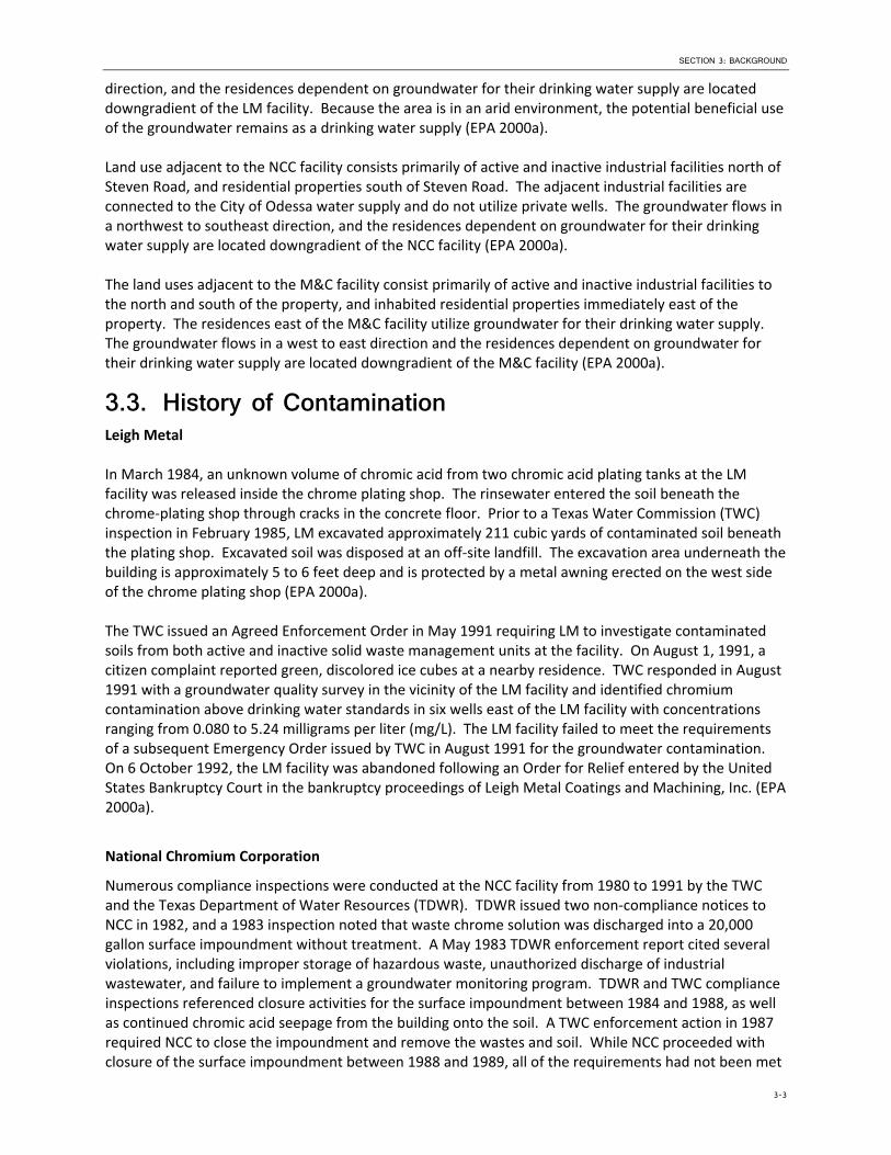
3.3. History of Contamination Leigh Metal
In March 1984, an unknown volume of chromic acid from two chromic acid plating tanks at the LM facility was released inside the chrome plating shop. The rinsewater entered the soil beneath the chrome‐plating shop through cracks in the concrete floor. Prior to a Texas Water Commission (TWC) inspection in February 1985, LM excavated approximately 211 cubic yards of contaminated soil beneath the plating shop. Excavated soil was disposed at an off‐site landfill. The excavation area underneath the building is approximately 5 to 6 feet deep and is protected by a metal awning erected on the west side of the chrome plating shop (EPA 2000a).
The TWC issued an Agreed Enforcement Order in May 1991 requiring LM to investigate contaminated soils from both active and inactive solid waste management units at the facility. On August 1, 1991, a citizen complaint reported green, discolored ice cubes at a nearby residence. TWC responded in August 1991 with a groundwater quality survey in the vicinity of the LM facility and identified chromium contamination above drinking water standards in six wells east of the LM facility with concentrations ranging from 0.080 to 5.24 milligrams per liter (mg/L). The LM facility failed to meet the requirements of a subsequent Emergency Order issued by TWC in August 1991 for the groundwater contamination. On 6 October 1992, the LM facility was abandoned following an Order for Relief entered by the United States Bankruptcy Court in the bankruptcy proceedings of Leigh Metal Coatings and Machining, Inc. (EPA 2000a).
National Chromium Corporation
Numerous compliance inspections were conducted at the NCC facility from 1980 to 1991 by the TWC and the Texas Department of Water Resources (TDWR). TDWR issued two non‐compliance notices to NCC in 1982, and a 1983 inspection noted that waste chrome solution was discharged into a 20,000 gallon surface impoundment without treatment. A May 1983 TDWR enforcement report cited several violations, including improper storage of hazardous waste, unauthorized discharge of industrial wastewater, and failure to implement a groundwater monitoring program. TDWR and TWC compliance inspections referenced closure activities for the surface impoundment between 1984 and 1988, as well as continued chromic acid seepage from the building onto the soil. A TWC enforcement action in 1987 required NCC to close the impoundment and remove the wastes and soil. While NCC proceeded with closure of the surface impoundment between 1988 and 1989, all of the requirements had not been met
3-3

SECTION 3: BACKGROUND
prior to the facility closing in 1993. Closure of the surface impoundment included the excavation of the liquids, sludges, and liner along with the excavation of other nearby spill areas (EPA 2000a).
Machine and Casting
A TDWR compliance inspection at the M&C facility in 1980 found an abandoned plating room, which contained a full chrome plating vat, and staining on the floors and walls of the room. A TWC compliance inspection in 1988 identified a chrome waste spill in the northeast portion of the facility property; also, the full plating vat was still present, and a large hole was discovered in the concrete floor of the plating room. Under the direction of the TWC, 48 drums of chromium‐contaminated soil, 18 over‐packed drums of chromium‐contaminated debris, the plating vat, and 220 gallons of spent chrome plating solution were removed from the facility. The facility was abandoned in 1988. TWC sampled the groundwater from nearby wells between 1989 and 1992 and identified chromium contamination in a private well 150 feet north of the M&C building at concentrations ranging from 0.825 to 3.84 mg/L (EPA 2000a).
EPA combined the three contaminant plumes into one site in 1996; during this time the Site was known as the Odessa Super Site prior to listing of the Site on the NPL. As a result, EPA realized cost savings by designing one centralized treatment facility to address all three contaminant plumes (EPA 2000a).
Chromium is the primary contaminant of concern (COC) at the Site. Additionally, 1,1‐dichloroethene (1,1‐DCE) was detected in two onsite monitoring wells at the NCC facility but was not detected at the LM or M&C facilities. Table 2 lists the contaminants that were detected during the remedial investigation/feasibility study (RI/FS) in various site media above human health‐based standards (EPA 2000a).
3.4. Initial Response TWC installed eight monitoring wells in December 1992 to investigate the groundwater contamination from the LM facility. Chromium concentrations from the two on‐site and six off‐site wells ranged from 0.050 mg/L to 4.30 mg/L. In September 1993, the TNRCC installed a water supply line from the City of Odessa to provide drinking water to the affected residences.
EPA proceeded with an emergency removal action between September and October 1996. During the removal, liquid and sludge wastes were removed from 13 vats, 85 drums, 83 pails, and numerous small containers at the NCC facility. The emptied drums and pails were crushed and placed in the empty vats in the plating shop. A total of 4,070 gallons of liquid waste, and 2,550 gallons of solid waste were removed for off‐site disposal. A total of 115,700 pounds of vat and tank sludge, 40,620 pounds of tank liquid waste, and 5,187,340 pounds of soil waste were removed from the NCC facility for off‐site disposal. The remaining excavated soil from the waste pile was consolidated into the former surface impoundment and covered with backfill dirt. Staged backfill dirt was leveled across the rest of the site (EPA 2000a).
A second EPA emergency response action in 1998 addressed the risk to human health caused by exposure to the chromium contaminated groundwater present in private drinking water wells by supplying bottled water to adjacent residences. A third EPA removal action initiated in 2000 connected those residences to the City of Odessa water supply to replace the current bottled water service and also addressed the risks posed by the abandoned plating room shops (EPA 2000a).
3-4

SECTION 3: BACKGROUND
EPA has conducted a site assessment of the adjacent Gulf Nuclear site and a separate emergency removal action was conducted by the EPA Radiological Emergency Response Team in 2001 (EPA 2000a, 2007).
3.5. Basis for Taking Action Based on the data collected during the RI/FS, it was determined that if the selected remedy in the ROD was not implemented, hazardous substances could be released from the Site and endanger public health, welfare, or the environment. The most significant threat is the current and future risks for an off‐site resident exposed to hexavalent chromium in groundwater. The ROD did not require remediation of the surface soil because the RI/FS did not identify the surface soils as a risk to human health and environment (EPA 2000a). However, the hexavalent chromium in vadose zone soil presented a possible continuing source of groundwater contamination. An interim cleanup level for hexavalent chromium in vadose zone soil was set at 1.0 milligram per kilogram (mg/kg), which is consistent with the applicable or relevant and appropriate requirements (ARARs) for groundwater, attains EPA’s risk management goal for the RA, and has been determined by EPA to be protective. Results of the predictive modeling conducted during the RD indicated that concentrations of hexavalent chromium in soil at the M&C and LM facilities were not sufficient to cause significant future groundwater contamination. Accordingly, only the vadose zone soils at the NCC facility are addressed in the LTRA. The interim soil cleanup level for vadose zone soil must be met at the NCC facility at the completion of the LTRA (Tetra Tech 2005b).
3-5

SPRAGUE ROAD GROUNDWATER PLUME SUPERFUND SITE SECOND FIVE-YEAR REVIEW REPORT
This page is intentionally left blank.
SECTION 4
Remedial Actions This section provides a description of the remedy objectives, selection, and implementation as required by the ROD and ROD Amendment for the site. It also describes the ongoing operations and maintenance (O&M) activities performed and overall progress made at the site in the period since completion of the first five‐year review. The EPA manages the site O&M activities. The site is currently considered a LTRA.
4.1. Remedy Selection The EPA signed the ROD on 29 September 2000. The ROD addressed long‐term environmental and human health risks associated with contaminated groundwater. Details of the RAOs and the selected remedy are discussed in the following paragraphs.
The RAOs established in the ROD were as follows (EPA 2000a):
Prevent exposure to contaminated groundwater, above acceptable risk levels;
Prevent or minimize further migration of the groundwater contaminant plume;
Prevent or minimize further migration of contaminants from source materials to groundwater; and
Return groundwaters to their expected beneficial uses wherever practicable.
The remedy selected in the ROD included the following (EPA 2000a):
Installation of groundwater extraction wells at each contaminant plume to maximize contaminant reduction and prevent further migration of the plume;
Treatment of the contaminated groundwater utilizing one of the presumptive remedies described in the Presumptive Response Strategy and Ex‐Situ Treatment Technologies for Contaminated Groundwater at CERCLA Sites (Office of Solid Waste and Emergency Response (OSWER) Directive 9283.1‐12, October 1996). Wastes generated during the treatment process would be transported to an off‐site location for disposal in accordance with Resource Conservation and Recovery Act (RCRA) and CERCLA requirements;
The re‐injection of the treated water into the aquifer utilizing one or a combination of the following: injection wells, dry wells, and/or infiltration galleries;
The use of infiltration galleries or other means to flush the hexavalent chromium from the vadose zone to levels that will ensure the area does not act as a potential source of contamination or prevent the restoration of the groundwater under future land‐use scenarios; and
Long‐term groundwater monitoring to evaluate the effectiveness of the groundwater extraction and disposal system and ensure there is no further exposure to contaminated groundwater above the applicable drinking standards.
The remedial goals for groundwater, as specified in the ROD, are presented in Table 3.
4-1

SECTION 4: REMEDIAL ACTIONS
4.2. Remedy Implementation The groundwater remediation system at the Site consists of an extraction well system, a treatment system, and an injection system for the return of treated water to the aquifer. Control is shared by three control centers—one at each of the three facilities. The groundwater treatment system is located at the LM facility (Tetra Tech 2004).
A network of recovery wells (7 at M&C, 27 at LM, and 23 at NCC) forms the groundwater recovery system. Recovery systems at M&C and NCC pump contaminated groundwater into local collection tanks. Transfer pumps transfer water from their respective collection tanks to the surge tank located in the LM facility. The recovery wells at the LM facility pump water directly to the surge tank (Tetra Tech 2004).
The recovery system is designed to provide secondary containment in the event of contaminated water leakage from the carrier pipe. The containment annulus of the double‐walled high‐density polyethylene (HDPE) pipe is connected at low points to 32 leak detection sumps across the Site. Each sump has a water sensing probe connected to a continuous monitor. In the event of a carrier pipe leak, the containment pipe will convey the water to the closest downstream sump. The water sensing probe in that sump will alert the continuous leak detection sump monitor in one of the facilities. The monitor beeps and prints out information pertaining to the leak, including its location (Tetra Tech 2004).
The treatment system is located at the LM facility and includes a surge tank, a pump tank, pumps, bag filters, and until December 12, 2010, an ion exchange system, followed by an effluent tank . The previous ion exchange system was removed for contractual reasons and a new water treatment system (Photo‐Cat) was procured. Complications in developing the Photo‐Cat system delayed the delivery until March 1, 2013. The Photo‐Cat has been installed and start‐up operations are underway. This treatment system, designed and manufactured by Purifics® ES Inc. (Purifics), consists of a Photo‐Cat Platform, and a DeWRS Chrome Recovery Platform (Purifics 2013). The Photo‐Cat system was procured to achieve significantly lower treatment goals for chromium levels than the prior ion exchange system, and lower long‐term O&M costs.
Water that collects in the surge tank gravity‐flows into the pump tank through a 10‐inch horizontal pipe connecting the two tanks about 11 feet above the finished floor. Settleable solids sink to the bottom of the surge tank before water flows from the surge tank into the pump tank. Water is transferred out of the pump tank through bag filters and through the Photo‐Cat Platform. On the Photo‐Cat platform citric acid is injected into the water to facilitate the reaction. The water is then mixed with titanium dioxide (TiO2) and passed through tubes that expose the water to ultraviolet (UV) light. The UV light converts the hexavalent chromium to trivalent chromium which then adsorbs onto the TiO2. The water passes through two cross flow filters which separate the flow stream from the TiO2. The treated water exits the Photo‐Cat to tank T‐2 and is then reinjected. The separated TiO2 slurry returns to the TiO2 accumulation tank and is reused to treat incoming water. A slipstream of the TiO2 is continuously removed. This material enters one of three DeWRS vessels. In these vessels the TiO2 is dewatered and concentrated. Once the level of TiO2 in the DeWRS vessel reaches preset levels, the TiO2 cleaning process begins. Air pressure is used to push the residual water from the TiO2. Heated sulfuric acid is then added and agitated to remove the adsorbed chromium. Air pressure is then used to push the acid from the DeWRS vessel back into the acid storage tank. Additional sulfuric acid is added to the acid storage tank as needed to maintain the pH of the acid solution. Water is added to the DeWRS vessel, agitated and also pushed out to remove any residual acid. This residual acid and water enters the chrome recovery tank. Sodium hydroxide is added to this tank to neutralize the pH. This causes the trivalent chromium to precipitate out as chromium hydroxide. This is removed from the system as a slurry into a drum next to the Photo‐Cat. The cleaned TiO2 is returned to TiO2 storage tank for reuse (Purifics 2013).
4-2

SECTION 4: REMEDIAL ACTIONS
The injection system consists of three separate networks of injection wells (8 wells at M&C, 8 wells at LM, and 27 wells at NCC). A vadose zone flushing system is also available at the NCC facility property, but has not been used to date. Injection pumps in the treatment building deliver treated water from the effluent tank to each of these well networks. (Tetra Tech 2004).
4.3. System Operations/Operation and Maintenance (O&M) O&M activities began in September 2003 upon completion of the groundwater treatment system (Tetra Tech 2005b). These activities are conducted to ensure the effectiveness, protectiveness, and integrity of the remedy. The O&M activities for the Site included routine O&M of the groundwater treatment system, as well as groundwater monitoring to monitor the effectiveness of the remedy. These activities are currently being conducted under the LTRA.
4.4. System Operation The Photo‐Cat treatment system at the Site is designed to run continuously; system shutdown is not a component of routine system operation. The system is designed to operate during routine maintenance, such as replacement of the bag filter (EA 2008b).
Site and systems assessments are performed daily and include the following (Tetra Tech 2004):
Driving to remote buildings M&C and NCC and observing the yards, buildings, and wells;
Checking all above‐ground system components (e.g., piping, tanks, flowmeters, and gate valves) for integrity on a daily basis;
Driving to all wells and along pipeline routes to visually check for leaks;
Checking all electrical panels and physical fixtures for any possible problems at remote buildings M&C, NCC, and LM; and
Verifying that the computer system at LM (in conjunction with visual inspection) is operating properly.
In order to determine whether the treatment system performs as required and discharge (treatment) criteria are met, the treatment system influent and effluent are monitored on a daily basis. Influent and effluent samples are collected and analyzed daily for hexavalent chromium using a Hach® DR 2800™ Portable Spectrophotometer field test kit. The Hach® field test kit has a reporting range of 30 microgram per Liter (µg/L) to 1,000 µg/L total chromium or hexavalent chromium. One effluent sample per week is submitted to a fixed laboratory for hexavalent and total chromium analysis in order to verify the daily testing (EA 2008b). The effluent data concentrations are discussed in Section 6.3.
4.5. Monitoring Program Routine groundwater monitoring began in March 2003, before RA activities were completed. Selected monitor wells, private wells, and recovery wells are sampled at the discretion of the EPA during each groundwater event. Table 4 lists the number of groundwater sampling events, by year, and applicable comments.
4-3

SECTION 4: REMEDIAL ACTIONS
The monitoring well network consists of 18 monitor wells and 22 privately owned wells at LM, 10 monitoring wells and 18 privately owned wells at M&C, and 39 monitoring wells and 10 privately owned wells at NCC. Attachment 1 provides a site layout map that illustrates the current monitoring well network.
Samples collected from the monitoring network are analyzed for target analyte list (TAL) metals via Contract Laboratory Program (CLP) SOW ISM01.3. Chromium results are presented in groundwater monitoring and semiannual operating reports. Data trends are discussed in Section 6.3.
4.6. O&M Cost The total cost of O&M at the Site from October 2008 through May 2013 is listed below:
Oct 2008 – Sep 2009 $1,004,000
Oct 2009 – Sep 2010 $1,749,000 (included in situ pilot test)
Oct 2010 – Sep 2011 $774,000
Oct 2011 – Sep 2012 $350,000
Oct 2012 – May 2013 $2,183,000 (included purchase of Photo‐Cat system)
4-4

SECTION 5
Progress Since the Last Five-Year Review The first five‐year review of the Sprague Road Groundwater Plume Superfund Site was completed in September 2008. The findings of the first five‐year review, the status of recommendations and follow‐up actions, the results of implemented actions, and the status of any other issues are described in the following sections.
5.1. First Five-Year Review The assessment of the Site during the first five‐year review was that the remedy was functioning as designed, and the extraction, treatment, and monitoring of the groundwater was being conducted as required under the 2000 Record of Decision (ROD). The pump and treat system had not achieved cleanup of the aquifer, but chromium concentrations had generally declined since system start‐up.
The following protectiveness statement was made in the First Five‐Year Review Report:
The remedy implemented at the Sprague Road Groundwater Plume Superfund Site currently protects human health and the environment. The groundwater extraction system has been constructed in accordance with the requirements of the ROD, and extraction, treatment and monitoring of the groundwater is being conducted as required. Long‐term protectiveness of the remedy will be verified by continued monitoring of the groundwater recovery and treatment system; sampling and analysis of the groundwater; and, by implementing the necessary actions to address the issues discussed in this Five‐Year Review Report. The remedy is expected to be fully protective when the groundwater performance goals are achieved through continued operation of the groundwater extraction and treatment system.
The first five‐year review of the site, completed in September 2008, identified the following issues and recommendations (EPA, 2008), which are also summarized in Table 5.
1. Issue: Increasing trend of chromium concentrations at select recovery wells in the NCC extraction system
Recommendation: Expand the groundwater monitoring network near the leading edge of the NCC chromium plume. Additional data is needed to assist in evaluating the changes in chromium concentrations recorded in select recovery wells.
Action Taken and Outcome: 22 additional nested monitoring wells were installed near the leading edge of the NCC chromium plume. These well are included in the groundwater monitoring program. Sampling of the first set of wells indicated that the chromium plume had migrated further downgradient. The second sets of wells were installed in 2013 and were sampled in June 2013.
2. Issue: Improve the capture zone evaluation for the groundwater extraction system.
Recommendation: Complete the development of a replacement groundwater model to improve the capture zone evaluation for the groundwater recovery system. Development of the new models is currently underway and is expected to be completed in time for the 2008 Annual Operation and Maintenance Report.
5-1

SECTION 5: PROGRESS SINCE THE LAST FIVE-YEAR REVIEW
Action Taken and Outcome: Updated groundwater model was developed and included in the 2008 Annual O&M Report. The groundwater model was updated again in October 2010 and included in the 2010 Annual O&M Report.
3. Issue: The use of institutional controls to protect the remedy effectiveness
Recommendation: Identify available institutional controls to protect the remedy effectiveness and prevent accidental exposure via private wells installed through the contaminated portion of the aquifer.
Action Taken and Outcome: The EPA/TCEQ are currently evaluating the administrative requirements for implementing the ICs at the site.
4. Issue: Minor repairs to monitor wells
Recommendation: Perform maintenance and repair work on the Site monitor wells. The locks should be replaced on all conventional monitor wells in order to prevent unauthorized access to the wells. The expansion plugs and PVC well caps should be replaced where necessary to prevent surface water infiltration into the monitor wells. The O‐rings on the well vault lids should be replaced where necessary to prevent surface water infiltration into the well vaults.
Action Taken and Outcome: Maintenance and minor repair work, including installing new pad locks, expansion plugs, PVC well caps and gaskets on the well vaults were completed to the monitor wells in 2009. However, during the site inspection monitoring wells needing minor repair were observed.
5. Issue: Improve Public Outreach
Recommendation: Increase the frequency of public updates concerning the sampling results and the progress of the remedy.
Action Taken and Outcome: Sample results are provided to landowners upon request. Local system operator maintains regular communication with numerous businesses and residences in the area.
5.2. Other Updates Since First Five-Year Review In March 2009, water line connections to 2515 Steven Road and 2517 Steven Road were installed to provide these residences with water from the City of Odessa water supply. In September 2011, 10 nested monitoring wells (NMW‐18A, NMW‐18B, NMW‐19A, NMW‐19B, NMW‐20A, NMW‐20B, NMW‐21A, NMW‐21B, NMW‐22A, and NMW‐22B) were installed downgradient of the NCC plume. In May 2013, 12 additional nested monitoring wells (NMW‐23A, NMW‐23B, NMW‐24A, NMW‐24B, NMW‐25A, NMW‐25B, NMW‐26A, MMW‐26B, NMW‐27A, NMW‐27B, NMW‐28A, and NMW‐28B) were installed downgradient of the NCC plume. The –A wells were completed above and the –B wells were completed below the clay lens separating the Trinity Sand. In September 2011, two new water supply wells (N‐7R and M‐1R) were installed to replace N‐7 and M‐1. Water supply wells N‐7 and M‐1 were plugged and abandoned. Groundwater samples for M‐1R indicated that it was not impacted. However, the sample from N‐7R exceeded the MCL. In May 2013, three new water supply wells were installed (N‐11R, N‐15, and N‐16). Well N‐11, replaced by N‐11R, and two old wells located by N‐10 and N‐11, and monitoring well NMW‐03 were plugged and abandoned. The old well near N‐11 and NMW‐3 was overdrilled prior to plugging and abandonment; the old well near N‐10 and N‐11 was not cased and did not require overdrilling. All the new water supply wells were completed below the clay lens.
An in situ remediation pilot test was performed to determine if this technology can enhance cleanup efforts. Three different amendments were injected into pilot test wells in the M&C facility area in July 2010. The results from the pilot test indicated that two of the products applied reduced the chromium concentrations; however, they released arsenic, iron, and manganese from the aquifer material. Water
5-2

SECTION 5: PROGRESS SINCE THE LAST FIVE-YEAR REVIEW
samples from some of the wells exhibited extremely bad odors. These secondary effects may limit the applicability of this technology at the site. The third amendment could not be successfully injected into the aquifer. A second round of pilot testing was performed in May 2013 using an amendment that was buffered to minimize the generation of metals. Groundwater monitoring will be used to evaluate the effectiveness of this amendment for wide‐scale application.
5-3

SPRAGUE ROAD GROUNDWATER PLUME SUPERFUND SITE SECOND FIVE-YEAR REVIEW REPORT
This page is intentionally left blank.

SECTION 6
Five-Year Review Process This second five‐year review for the Sprague Road Groundwater Plume Superfund Site has been conducted in accordance with EPA’s Comprehensive Five‐Year Review Guidance dated June 2001 (EPA, 2001). The review process included a site inspection, and a review of the applicable data and reports covering the remedy implementation, performance monitoring, and O&M. The activities conducted as part of this review and specific findings are described in the following sections.
6.1. Administrative Components This second five‐year review was led by Mr. Vince Malott, EPA Remedial Project Manager. Texas Commission on Environmental Quality (TCEQ) and EA Engineering, Science, and Technology, Inc. (EA) personnel assisted in the review process. The representatives from TCEQ were Mr. Alan “Buddy” Henderson, State Project Manager for the site, and Mr. Jim Haley. EA’s team members included Mr. Stan Wallace, Ms. Reshma Hooda, Mr. Javier Manzano, and Mr. Alan Izard.
In October 2012, the review team established the review schedule, which included the following components:
Document review Site inspection/technology review Interviews ARARs review Data review Five‐Year Review Report development and review.
6.2. Community Involvement Upon signature, a copy of the Second Five‐Year Review Report will be available online at http://www.epa.gov/superfund/cleanup/postconstruction/5yr.htm and at the following information repositories: (1) U.S. EPA Region 6, 1445 Ross Avenue, Dallas, Texas 75202; and (2) TCEQ, 12100 Park 35 Circle, Austin, Texas 78753. A notice will then be published in the local newspaper to summarize the findings of the review and announce the availability of the report at the information repositories.
6.3. Document Review The five‐year review for the Site included a review of relevant documents, including the ROD, Final Design Report, RA Report, O&M Plan, Operating Reports, Groundwater Monitoring Reports, In situ Pilot Test Report, and Photo‐Cat Pilot Test Summary Report. Complete references for the documents reviewed are provided in Attachment 2.
6.4. Data Review Data reviewed consisted of:
Groundwater Monitoring Report, December 2008 (EA 2009a);
Semi‐Annual Operating Report, 1 October 2008 through 31 March 2009 (EA 2009b);
Groundwater Monitoring Report, May 2009 (EA 2009c);
6-1
SECTION 6: FIVE-YEAR REVIEW PROCESS
Annual Report for Operation and Maintenance, 1 October 2008 through 30 September 2009 (EA 2009d);
Groundwater Monitoring Report, October 2009 (EA 2009e);
Semi‐Annual Operating Report, 1 October 2009 through 31 March 2010 (EA 2010a);
Annual Report for Operation and Maintenance, 1 October 2009 through 30 September 2010 (EA 2010b);
Groundwater Monitoring Report, August 2010 (EA 2010c);
In situ Pilot Test Results Report, February 2011 (EA 2011a);
Semi‐Annual Operating Report, 1 October 2010 through 31 March 2011 (EA 2011b);
Groundwater Monitoring Report, April 2011 (EA 2011c);
Photo‐Cat Pilot Test Summary Report, October 2011, (EA 2011d)
Annual Report for Operation and Maintenance, 1 October 2010 through 30 September 2011 (EA 2011e);
Groundwater Monitoring Report, July 2011 (EA 2011f);
Groundwater Monitoring Report, November 2011 (EA 2012a);
Annual Operating Report, 1 October 2011 through 30 September 2012 (EA 2012b);
Groundwater Monitoring Report, November 2012 (EA 2013).
Groundwater Data Review
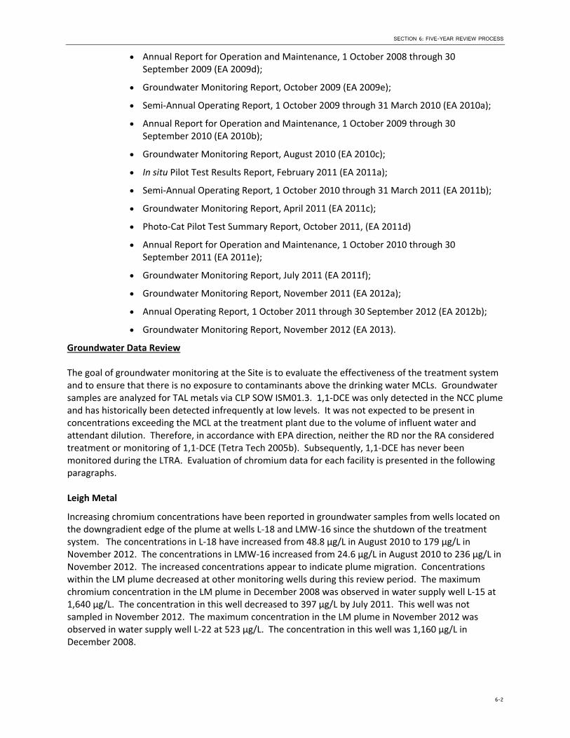
The goal of groundwater monitoring at the Site is to evaluate the effectiveness of the treatment system and to ensure that there is no exposure to contaminants above the drinking water MCLs. Groundwater samples are analyzed for TAL metals via CLP SOW ISM01.3. 1,1‐DCE was only detected in the NCC plume and has historically been detected infrequently at low levels. It was not expected to be present in concentrations exceeding the MCL at the treatment plant due to the volume of influent water and attendant dilution. Therefore, in accordance with EPA direction, neither the RD nor the RA considered treatment or monitoring of 1,1‐DCE (Tetra Tech 2005b). Subsequently, 1,1‐DCE has never been monitored during the LTRA. Evaluation of chromium data for each facility is presented in the following paragraphs.
Leigh Metal
Increasing chromium concentrations have been reported in groundwater samples from wells located on the downgradient edge of the plume at wells L‐18 and LMW‐16 since the shutdown of the treatment system. The concentrations in L‐18 have increased from 48.8 µg/L in August 2010 to 179 µg/L in November 2012. The concentrations in LMW‐16 increased from 24.6 µg/L in August 2010 to 236 µg/L in November 2012. The increased concentrations appear to indicate plume migration. Concentrations within the LM plume decreased at other monitoring wells during this review period. The maximum chromium concentration in the LM plume in December 2008 was observed in water supply well L‐15 at 1,640 µg/L. The concentration in this well decreased to 397 µg/L by July 2011. This well was not sampled in November 2012. The maximum concentration in the LM plume in November 2012 was observed in water supply well L‐22 at 523 µg/L. The concentration in this well was 1,160 µg/L in December 2008.
6-2

SECTION 6: FIVE-YEAR REVIEW PROCESS
National Chromium Corporation
Sampling of the nested wells installed downgradient of the NCC plume in September 2011 and water supply well N‐7R indicated the presence of chromium in groundwater downgradient of the groundwater recovery system both above and below the clay lens. Sampling also indicated the presence of chromium in groundwater collected from downgradient water supply wells N‐10 and N‐11. The concentrations detected in the groundwater from downgradient wells may indicate plume migration as a result of the groundwater extraction and treatment system being shut down. Additionally, the concentrations detected in groundwater above and below the clay lens may indicate vertical migration of the contamination. The vertical migration may be related to private water supply wells, which were typically installed without a casing through the clay lens. Concentrations in the NCC plume declined at other monitoring wells during this period. The maximum chromium concentration in December 2008 was observed in monitoring well NMW‐3 at 2,250 µg/L. The concentration in this well decreased to 822 µg/L by November 2012. The maximum concentration in November 2012 was observed in monitoring well NMW‐19A at 1,410 µg/L.
Machine and Casting
Water supply well M‐39, located on the downgradient edge of the plume, has reported increasing concentrations since the shutdown of the treatment system, indicating possible plume migration. Monitoring well MMW‐10, located near the source area, has increased in chromium concentrations since the shutdown of the treatment system. Overall, there is no apparent trend for the chromium concentrations in the MC plume. The maximum chromium concentration in December 2008 was observed in monitoring well MMW‐7 at 1,450 µg/L. The concentration in this well decreased to 261 µg/L by November 2012. The maximum concentration in November 2012 was observed in monitoring well MMW‐10 at 1,830 µg/L. This concentration increased from 253 µg/L in December 2008.
6.5. System Flowrates Since October 2008, 175.2 million gallons of groundwater have been extracted and treated and approximately 474.3 pounds of chromium have been removed (EA 2011c). Since the system was started in 2003, 643 million gallons of groundwater have been extracted and treated and approximately 3,117 pounds of chromium have been removed and (EA 2011c). The average monthly flowrates for the treatment system during October 2008 to September 2009, October 2009 to September 2010, and October 2010 to December 2010 were 157 gallons per minute (gpm), 151 gpm, and 144 gpm, respectively (EA 2009d, 2010b, 2011c). These flow rates are well below the design flow rate of 528 gpm (Tetra Tech 2002a). The treatment system has never operated at the design flowrate. The design rate was predicted by the groundwater model, which was based on hydraulic parameters obtained from short‐term single well pumping tests and two 24‐hour pumping tests. Neither type of pumping test was of sufficient duration to observe long‐term sustained yield (EA 2008b).
The existing groundwater model was revised in October 2010. The new model simulated three difference release areas (M&C, LM, and NCC), each with its own extraction and injection well network. In the previous model, all groundwater flow was simulated as steady‐state. In the new model transient conditions were used and particle tracking was performed. The October 2010 model indicated that the plume at LM was being fully captured, but part of the M&C and NCC plumes were not captured with the pumping and injection strategy at the time.
6.6. System Influent and Effluent Concentrations During initial startup in 2003, the average monthly influent hexavalent chromium concentrations ranged from 670 µg/L to 1,060 µg/L (Tetra Tech 2005b). The average monthly influent total chromium
6-3
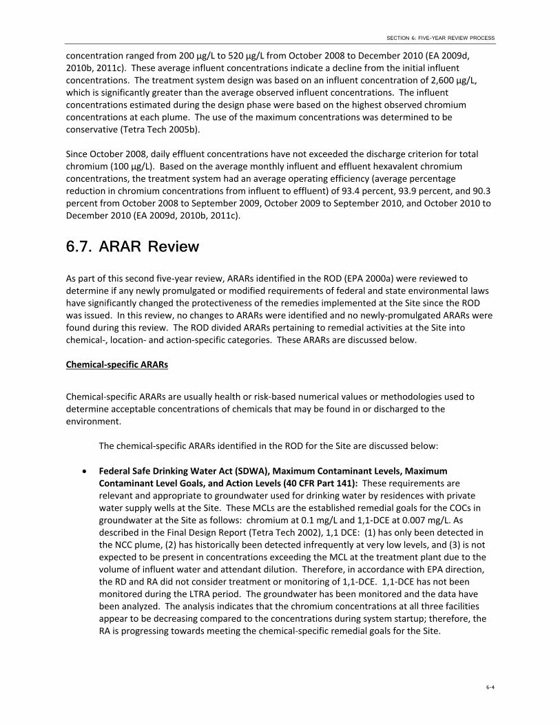
SECTION 6: FIVE-YEAR REVIEW PROCESS
concentration ranged from 200 μg/L to 520 μg/L from October 2008 to December 2010 (EA 2009d, 2010b, 2011c). These average influent concentrations indicate a decline from the initial influent concentrations. The treatment system design was based on an influent concentration of 2,600 µg/L, which is significantly greater than the average observed influent concentrations. The influent concentrations estimated during the design phase were based on the highest observed chromium concentrations at each plume. The use of the maximum concentrations was determined to be conservative (Tetra Tech 2005b).
Since October 2008, daily effluent concentrations have not exceeded the discharge criterion for total chromium (100 µg/L). Based on the average monthly influent and effluent hexavalent chromium concentrations, the treatment system had an average operating efficiency (average percentage reduction in chromium concentrations from influent to effluent) of 93.4 percent, 93.9 percent, and 90.3 percent from October 2008 to September 2009, October 2009 to September 2010, and October 2010 to December 2010 (EA 2009d, 2010b, 2011c).
6.7. ARAR Review As part of this second five‐year review, ARARs identified in the ROD (EPA 2000a) were reviewed to determine if any newly promulgated or modified requirements of federal and state environmental laws have significantly changed the protectiveness of the remedies implemented at the Site since the ROD was issued. In this review, no changes to ARARs were identified and no newly‐promulgated ARARs were found during this review. The ROD divided ARARs pertaining to remedial activities at the Site into chemical‐, location‐ and action‐specific categories. These ARARs are discussed below.
Chemical‐specific ARARs
Chemical‐specific ARARs are usually health or risk‐based numerical values or methodologies used to determine acceptable concentrations of chemicals that may be found in or discharged to the environment.
The chemical‐specific ARARs identified in the ROD for the Site are discussed below:
Federal Safe Drinking Water Act (SDWA), Maximum Contaminant Levels, Maximum Contaminant Level Goals, and Action Levels (40 CFR Part 141): These requirements are relevant and appropriate to groundwater used for drinking water by residences with private water supply wells at the Site. These MCLs are the established remedial goals for the COCs in groundwater at the Site as follows: chromium at 0.1 mg/L and 1,1‐DCE at 0.007 mg/L. As described in the Final Design Report (Tetra Tech 2002), 1,1 DCE: (1) has only been detected in the NCC plume, (2) has historically been detected infrequently at very low levels, and (3) is not expected to be present in concentrations exceeding the MCL at the treatment plant due to the volume of influent water and attendant dilution. Therefore, in accordance with EPA direction, the RD and RA did not consider treatment or monitoring of 1,1‐DCE. 1,1‐DCE has not been monitored during the LTRA period. The groundwater has been monitored and the data have been analyzed. The analysis indicates that the chromium concentrations at all three facilities appear to be decreasing compared to the concentrations during system startup; therefore, the RA is progressing towards meeting the chemical‐specific remedial goals for the Site.
6-4

SECTION 6: FIVE-YEAR REVIEW PROCESS
Federal RCRA, Identification and Listing of Hazardous Waste (40 CFR Part 261): The ROD identified these requirements as applicable to solid wastes generated during the treatment of contaminated groundwater which may be classified as a hazardous waste, if they exhibit any RCRA characteristics. Ion exchange resin was not a hazardous waste as it was regenerated by Siemens; therefore, this requirement did not apply to the management and handling of the regenerated resin. Used bag filters, a waste generated from the treatment process, are stored on‐site in a drum. They will be analyzed using the Toxicity Characteristic Leaching Procedure (TCLP) before disposal to determine if hazardous waste requirements apply. The chromium hydroxide produced by the Photo‐Cat system during operation will need to be analyzed via TCLP before disposal to determine if hazardous waste requirements apply.
Federal RCRA, Land Disposal Restrictions (40 CFR Part 268): These requirements were identified as applicable to hazardous wastes generated from the treatment of the contaminated groundwater. Ion exchange resin was not a hazardous waste as it was regenerated by Siemens; therefore, this requirement did not apply. Used bag filters, a waste generated from the treatment process, are stored on‐site in a drum. They will be analyzed using TCLP before disposal to determine if Land Disposal Requirements apply. The chromium hydroxide produced by the Photo‐Cat system during operation will need to be analyzed via TCLP before disposal to determine if Land Disposal Requirements apply.
No other chemical‐specific ARARs for the Site were identified during the five‐year review process, and no new chemical‐specific requirements pertaining to the Site have been promulgated since 2000.
Location‐specific ARARs
Location‐specific ARARs are restrictions on remedial activities solely based on the location of the remedial activity. The location‐specific ARARs identified in the Preliminary Design Report for the Site are discussed below:
Groundwater Restoration: The ROD identified the State of Texas Rules, Groundwater Protection Act (Texas Water Code, Chapter 26, Subchapter J, 401‐ 406) as a location‐specific ARAR. This statute was identified as applicable because the Site’s underlying groundwater is impacted, and the statute requires groundwater to be restored, if feasible. This ARAR continues to be met through the implementation of this RA under the 2000 ROD to address impacted groundwater and restore state groundwater, as feasible.
Construction Permits: The ROD identified the Ector County Pipeline/Utility Agreement Order which requires permits for construction in right‐of‐ways and agreements for roadway crossings. This ARAR was identified as applicable for the construction of all pipelines in roadways and alleys and the installation of borings requiring crossing beneath paved streets after approval of special variance requests. This ARAR was met during construction of the treatment system (Tetra Tech 2002).
No other location‐specific ARARs for the Site were identified during the five‐year review process, and no new location‐specific requirements pertaining to the Site have been promulgated since 2000.
6-5

SECTION 6: FIVE-YEAR REVIEW PROCESS
Action‐specific ARARs
Action‐specific ARARs are usually technology‐ or activity‐based requirements or limitations on actions or conditions taken with respect to specific substances. These requirements are triggered by the particular remedial activities that are selected to accomplish the remedy. The action‐specific ARARs specified in ROD are discussed below:
Federal RCRA, Section 3020(b): The ROD identified this requirement which provides exemption from the ban on underground injection of treated contaminated groundwater into or above an underground source of drinking water if the following three conditions are met: (1) the injection is a CERCLA response action or a RCRA corrective action; (2) contaminated groundwater must be treated to substantially reduce hazardous constituents prior to such injection; and (3) the response action or corrective action must be sufficient to protect human health and the environment upon completion. The injection wells installed and operated as part of the RA are meeting all three requirements of this ARAR as the action is being conducted under CERCLA; groundwater is being treated to substantially reduce hazardous constituents as demonstrated in the influent and effluent analysis, and the RA is operating in such a manner to protect human health and the environment.
Federal SDWA, Underground Injection Control Regulations (40 CFR § 141.13): The ROD identified these regulations which provide exemptions from Underground Injection Control (UIC) permitting process to wells used to re‐inject treated groundwater into the same formation from which it was withdrawn. The State of Texas controls underground injection under 30 TAC 331. As mentioned in the ROD, acquisition of permits will not be necessary for the use of injection wells or injection galleries for the disposal of treated groundwater. The injection wells installed and operated during the RA were exempt from UIC permitting under these provisions of the SDWA. Based upon review of existing site documentation, this ARAR appears to have been met.
Federal RCRA, Standards Applicable to Generators of Hazardous Waste (40 CFR Part 262): The ROD identified these requirements for management and manifesting hazardous waste for off‐site transportation and disposal as being applicable to potential hazardous wastes generated from the treatment of the contaminated groundwater. Ion exchange resin was not a hazardous waste as it is regenerated by Siemens; therefore, this requirement did not apply. Used bag filters are stored onsite in a drum. They will be analyzed using the TCLP before disposal to determine if hazardous waste generator requirements apply. The chromium hydroxide produced by the Photo‐Cat system during operation will need to be analyzed via TCLP before disposal to determine if hazardous waste generator requirements apply.
No other action‐specific ARARs for the Site were identified during the five‐year review process, and no new action‐specific requirements pertaining to the Site have been promulgated since 2000.
6.8. Site Inspection A Site inspection was conducted from May 20–22, 2013 to assess the condition of the Site and the effectiveness of measures employed to protect human health and the environment from the contaminants still present at the Site. Attendees included: Mr. Vince Malott (EPA), Mr. Alan “Buddy” Henderson (TCEQ), Mr. Jim Haley (TCEQ), Mr. Stan Wallace (EA), Ms. Reshma Hooda (EA), Mr. Javier Manzano (EA), and Mr. Alan Izard (EA). The inspection team visited the LM, M&C, and NCC facilities.
6-6

SECTION 6: FIVE-YEAR REVIEW PROCESS
The Site inspection checklist is provided in Attachment 3. The Site inspection photographs are provided in Attachment 4.
The Photo‐Cat system had been delivered to the site, but was not yet operational at the time of the site inspection. The site inspection included examining and evaluating the conditions of the extraction, injection, and monitoring wells and subsurface pull boxes. Several of the well vaults and electrical control boxes were filled with water. Flooding of electrical components in control box and well vaults have been a persistent problem at the Site. Drainage holes were installed in the electrical pull boxes, but were not installed in the well vaults except for NRW‐05. The lack of water in NRW‐05 indicates that this may have been effective.
Other issues with the well vaults and pull boxes include the accumulation of rust and dirt, missing flow meters leaving several injection wells nonoperational, missing or loose well caps, cracked or damaged concrete pads, and loose or corroded electrical lines outside of control boxes. Examples of these issues can be seen in the photographs included in Attachment 4.
6.9. Interviews Site interviews were not conducted during this five‐year review site visit. Due to the system being nonoperational at the time of the visit, site interviews have been postponed to a later date. The responses from these interviews will be presented in a Five‐Year Review Report Addendum that will be prepared in the next 12 to 18 months.
6-7

SPRAGUE ROAD GROUNDWATER PLUME SUPERFUND SITE SECOND FIVE-YEAR REVIEW REPORT
This page is intentionally left blank.

SECTION 7
Technical Assessment In accordance with the EPA Five‐Year Review Guidance (EPA 2001), a determination of the protectiveness of the selected remedy for a site will be determined by a technical assessment examining the following three questions:
Question A: Is the remedy functioning as intended by the decision documents?
Question B: Are the assumptions used at the time of the remedy selection still valid?
Question C: Has any other information come to light that could call into question the protectiveness of the remedy?
The technical assessment was conducted by reviewing the ROD, O&M Plan, Annual and Semi‐annual System Operating Reports, Groundwater Monitoring Reports, In situ Pilot Test Results Report, Photo‐Cat Pilot Test Summary Report, and by conducting a site visit. The technical assessment is presented in the following sections. This assessment will be updated in the Five‐Year Review Report Addendum that will be prepared in the next 12 to 18 months.
7.1. Question A: Is the remedy functioning as intended bythe decision documents?
The document that details the remedial decisions for the site is the September 2000 ROD. The LTRA is ongoing for the site. This section discusses the RA performance, system O&M, costs, ICs, monitoring activities, opportunitites for optimization, and early indicators of potential remedy problems.
Remedial Action Performance—The selected remedy included the following elements: a groundwater extraction and treatment system, a treated groundwater re‐infiltration system, an infiltration gallery for flushing hexavalent chromium through vadose zone soils, and a long‐term groundwater monitoring program.
The system was completed in 2003. The groundwater extraction, treatment, and reinjection systems operated as intended by the decision documents until December 12, 2010. The ion exchange system was shut down for contractual reasons. After performing multiple bench‐scale tests and pilot studies, an UV light‐activated slurry catalyst system (Photo‐Cat) was selected to replace the ion exchange water treatment system. The Photo‐Cat system was delivered to the site on March 1, 2013 and startup operations are underway.
The cleanup goals have not yet been achieved. The following trends in concentrations of chromium in groundwater have been observed:
Leigh Metal: Increasing chromium concentrations have been reported in groundwater samples from wells located on the downgradient edge of the plume at wells L‐18 and LMW‐16 since the shutdown of the treatment system. The concentrations in L‐18 have increased from 48.8 µg/L in August 2010 to 179 µg/L in November 2012. The concentrations in LMW‐16 increased from 24.6 µg/L in August 2010 to 236 µg/L in November 2012. The increased concentrations appear to indicate plume migration. Concentrations within the LM plume decreased at other monitoring wells during this review period. The maximum chromium concentration in the LM plume in December
7-1

SECTION 7: TECHNICAL ASSESSMENT
2008 was observed in water supply well L‐15 at 1,640 µg/L. The concentration in this well decreased to 397 µg/L by July 2011. This well was not sampled in November 2012. The maximum concentration in the LM plume in November 2012 was observed in water supply well L‐22 at 523 µg/L. The concentration in this well was 1,160 µg/L in December 2008.
National Chromium Corporation: Sampling of the nested wells installed downgradient of the NCC plume in September 2011 and water supply well N‐7R indicated the presence of chromium in groundwater downgradient of the groundwater recovery system both above and below the clay lens. Sampling also indicated the presence of chromium in groundwater collected from downgradient water supply wells N‐10 and N‐11. The concentrations detected in the groundwater from downgradient wells may indicate plume migration as a result of the groundwater extraction and treatment system being shut down. Additionally, the concentrations detected in groundwater above and below the clay lens may indicate vertical migration of the contamination. The vertical migration may be related to private water supply wells, which were typically installed without a casing through the clay lens. Concentrations in the NCC plume declined at other monitoring wells during this period. The maximum chromium concentration in December 2008 was observed in monitoring well NMW‐3 at 2,250 µg/L. The concentration in this well decreased to 822 µg/L by November 2012. The maximum concentration in November 2012 was observed in monitoring well NMW‐19A at 1,410 µg/L.
Machine and Casting: Water supply well M‐39, located on the downgradient edge of the plume, has reported increasing concentrations since the shutdown of the treatment system, indicating possible plume migration. Monitoring well MMW‐10, located near the source area, has increased in chromium concentrations since the shutdown of the treatment system. Overall, there is no apparent trend for the chromium concentrations in the MC plume. The maximum chromium concentration in December 2008 was observed in monitoring well MMW‐7 at 1,450 µg/L. The concentration in this well decreased to 261 µg/L by November 2012. The maximum concentration in November 2012 was observed in monitoring well MMW‐10 at 1,830 µg/L. This concentration increased from 253 µg/L in December 2008.
Maximum concentrations at LM and NCC have decreased. Since December 2008, no trend is apparent in the concentrations at MC. Data from downgradient wells indicate that all three plumes have migrated while the groundwater treatment system has been shut down. Vertical migration is suggested by the concentrations from the nested wells at NCC that were installed above and below the clay lens.
Well maintenance—The condition of the recovery and injection wells has deteriorated during the time the treatment system has been down. Standing water was observed in some of the well vaults, pipe and vaults were rusty, the electric junction boxes in the vaults were open and contained water, rust, and dirt, the well caps were not in place on many of the wells, and some of the concrete pads were cracked or damaged, and some of the electrical wires were loose or corroded. Additionally, some of the monitoring wells need minor repairs as well.
Cost of System Operation/O&M—The total cost of operation and maintenance at the Site from October 2008 through May 2013 was :
7-1

SECTION 7: TECHNICAL ASSESSMENT
Oct 2008 – Sep 2009 $1,004,000
Oct 2009 – Sep 2010 $1,749,000 (includes in situ pilot test)
Oct 2010 – Sep 2011 $774,000
Oct 2011 – Sep 2012 $350,000
Oct 2012 – May 2013 $2,183,000 (includes purchase of Photo‐Cat system)
Implementation of Institutional Controls and Other Measures—ICs (legal restrictions that protect a remedy and prevent human exposure) are an issue that is being evaluated at Superfund sites. In 2000 when the ROD was issued for the Site, ICs were not considered to be a necessary remedy component. As a result, the remedy described in the ROD did not include ICs. No ICs are currently in place to prevent installing wells in or downgradient of the contaminant plume. The EPA and TCEQ are currently evaluating the administrative requirements for implementing the ICs at the site. If administrative delays prevent the implementation of the IC by the end of the LTRA period, then the EPA will continue to work with the TCEQ to implement the available IC options.
In situ remediation is being considered as a remedial alternative or enhancement to pump and treat. Based on a pilot test performed in July 2010, this method can reduce the chromium concentrations, but the secondary effects (release of arsenic, iron and manganese and foul odors) may limit the applicability of this technology. A second round of pilot testing was performed in May 2013 with a buffered amendment to minimize the secondary effects. Groundwater monitoring will be used to evaluate the effectiveness of this amendment for wide‐scale application.
Monitoring Activities. Monitoring activities associated with the groundwater extraction and treatment system included observing the yards, buildings, and wells at the remote M&C and NCC facilities; checking all above‐ground system components; and verifying that the computer system at LM is operating properly.
Opportunities for Optimization. Groundwater modeling software (i.e., MODFLOW by Aquaveo) can be used in conjunction with flow rates and concentration data to determine an optimal pumping and injection strategy. Groundwater monitoring could also be optimized using the revised groundwater models and/or optimization software (i.e., MAROS) to reduce costs associated with sampling. In situ treatment of the chromium plume could greatly reduce or eliminate groundwater pumping in portions of the plume.
Historically, ion exchange has been used to treat the recovered groundwater. This required that the resin be removed and transported offsite for regeneration. The use of the Photo‐Cat system eliminates the need for the long distance transportation of the resin for regeneration.
Groundwater Recovery Rates—Groundwater recovery rates are lower than initially planned (from an estimated 528 gpm) in the final design report (Tetra Tech 2002) to an actual average recovery rate of 151 gpm. The lower recovery rate may increase remediation timeframe over initial estimates.
Groundwater Monitoring—Groundwater monitoring was performed periodically to evaluate the chromium concentrations in the groundwater.
Early Indicators of Potential Remedy Problems—The increase in chromium concentrations in downgradient wells in all three release areas (M&C, LM, and NCC) indicate that the plume is migrating. This is due to the groundwater treatment system being shut down from December 2010 to June 2013.
7-2

SECTION 7: TECHNICAL ASSESSMENT
Chromium concentrations detected in water supply wells and nested monitoring wells installed below the clay lens in the NCC area indicate vertical migration of the contamination.
7.2. Question B: Are the exposure assumptions, toxicitydata, cleanup levels, and remedial action objectives(RAOs) used at the time of remedy selection stillvalid?
This section addresses changes in environmental standards, newly promulgated standards, and To‐Be‐Considered (TBCs) criteria; changes in exposure pathways; changes in toxicity and other contaminant characteristics during the five‐year review period; and, progress toward meeting the RAOs.
Changes in Environmental Standards, Newly Promulgated Standards, and TBCs. Environmental standards (referred to as ARARs) for this Site were identified in the ROD. The second five‐year review for this Site included identification and evaluation of changes in the ROD‐specified ARARs and TBCs to determine whether such changes may affect the protectiveness of the selected remedy. The ARARs and TBCs identified by the ROD for the Site include chemical‐ and action‐specific requirements for the remedy.
The TCEQ and Federal regulations have not been revised so that the effectiveness of the remedy at the Site would be called into question. The MCLs applicable to the groundwater contamination at the Site have not been revised since the ROD was signed. No new regulations have been issued by the State of Texas or the Federal government that would call into question the effectiveness of the remedy. The remedy selected for the Site followed the EPA’s Presumptive Response Strategy and Ex‐Situ Treatment Technologies for Contaminated Groundwater at CERCLA Sites (OSWER Directive 9283.1‐12, October 1996), to provide a presumptive response strategy and applicable treatment technologies for the COCs.
Changes in Exposure Pathways— Land use within the Site remains a mix of residential and industrial operations. No new source areas have been identified as part of this five‐year review. Waterline connections to 2515 Steven Road and 2517 Steven Road were installed to provide these residences with water from the City of Odessa water supply. Water supply wells M‐1, N‐7, and N‐11 have been replaced with new wells M‐1R, N‐7R, and N‐11R. New water supply wells N‐15 and N‐16 have been drilled for residents. These new water supply wells and the waterline connections were installed in an attempt to prevent the use of groundwater contaminated with chromium above the MCL, since some residents continue to use groundwater for irrigation. The previous extension of water supply lines to residences in the area as well as the operation of the P&T system has reduced the human health exposure pathways present at the Site. Monitoring of private residential wells that are used for water supply is conducted as part of the overall groundwater monitoring program.
New Contaminants of Concern (COCs) and/or Contaminant Sources. No new source areas have been identified as part of this five‐year review. No new or emerging contaminants associated with the past release of chromium have been identified. The in‐situ chemical reduction pilot test conducted at the Machine and Casting facility has generated byproducts of concern that include manganese, iron, and arsenic. Continued monitoring will determine if potential off‐site migration from the Machine and Casting facility will require steps to promote an oxidizing environment that would lead to precipitation of the manganese, iron, and arsenic.
Changes in Toxicity and Other Contaminant Characteristics. No changes to the toxicity of chromium has been identified for the site as part of this five‐year review. The ROD established Remedial Goals for chromium and 1,1‐DCE in groundwater. The Remedial Goals were based on their corresponding EPA
7-3

SECTION 7: TECHNICAL ASSESSMENT
MCLs: chromium at 0.1 mg/L and 1,1‐DCE at 0.007 mg/L. The EPA MCLs for these COCs has not changed since the ROD. The Remedial Goal for chromium in vadose zone soil (1 mg/kg) was based on protection of groundwater at the EPA MCL of 0.1 mg/L, which has not changed since the ROD. Therefore, the Remedial Goals established in the ROD for chromium and 1,1‐dichloroethene remain protective of human health.
Hexavalent chromium was not identified as a COC in the ROD, so Remedial Goals were not established. In September 2010, the EPA released a draft IRIS assessment for hexavalent chromium, for the oral route of exposure only, for peer review and public comment. An independent expert peer review panel met in May 2011 to review the draft assessment. In their final report, the peer review panel urged EPA to consider the results of research that would soon be completed and peer‐reviewed that could provide relevant scientific information that may inform the findings of the assessment. Given the uncertainty over the time frame for future changes, this does not constitute new information which could call into question the protectiveness of the remedy at the Site and no changes to cleanup levels for this Site are appropriate or necessary at this time. Once toxicity values are established, EPA will evaluate hexavalent chromium in groundwater to ensure that the remedy remains protective of human health.
Progress Toward Meeting the RAOs. Since the groundwater extraction and treatment system was shut‐down in December 2010, the remedy is not preventing plume migration or restoring the groundwater to its beneficial use as a drinking water supply. Ongoing groundwater sampling at private water supply wells has been used to identify well locations that require abandonment and replacement to prevent human exposure.
7.3. Question C: Has Any Other Information Come toLight that Could Call into Question the Protectivenessof the Remedy?
A review of the site data has not identified any new or previously unidentified risks. Due to the depth below ground surface of the water table, the groundwater does not discharge to any nearby surface water body, and thus there was no complete exposure pathway for ecological receptors at this site. The protectiveness of the remedy has not been affected by natural disasters or other weather‐related events. There is no other information that has been identified during this five‐year review that would call into question the protectiveness of the remedy.
7.4. Technical Assessment Summary The technical assessment, based on the data review, site inspection, and technical evaluation indicates that the remedial actions selected for the Sprague Road Site have been implemented as intended by the decision document. However, the protectiveness of the groundwater extraction and treatment systemcannot be determined at this time, because the new treatment system (Photo‐Cat) is currently undergoing start‐up operations. As a result, the capture zone for the extraction system cannot be evaluated until the treatment system is restarted and performance data is collected from the extraction wells and monitor wells.
As determined during the site inspection (Section VI.F), many site well vaults and monitor wells were observed to require maintenance to replace the locks, well plugs, and/or O‐rings on the well vaults. Other issues with the extraction and injection well vaults included the accumulation of rust and dirt, missing flow meters, corroded piping, missing or loose well caps, damaged concrete pads surrounding the well vaults, loose or corroded electrical lines, and standing water within the vault. Corrective
7-4

SECTION 7: TECHNICAL ASSESSMENT
measures are required to prevent surface water intrusion into the wells and well vaults and to maintain the security of the wells.
ICs were not included as a remedy component in the ROD. The addition of ICs would provide an administrative component to ensure long‐term remedy protectiveness.
The efficacy of in situ remediation as a method to reduce hexavalent chromium to trivalent chromium in groundwater is ongoing at the Machine and Casting facility. The pilot test injection of a fourth commercial product was completed in May 2013, and groundwater monitoring of the effectiveness of the amendment performance is ongoing at the Site. The applicability of this amendment as a method for in‐situ remediation will be determined during the next 12‐months.
Since implementation of the remedy, it is apparent that the groundwater extraction rate is much lower than assumed in the original design documents. A declining water table across the Site and performance of individual extraction wells are contributing factors affecting the total flow rate.
The assumptions used at the time the remedy was selected are still valid. The LTRA has been adjusted over time based on changes in contaminant concentrations in site groundwater. No changes in contaminant toxicity or other contaminant characteristics were identified that affect the cleanup goals established for the site or the protectiveness of the remedy. No new laws or regulations have been promulgated or enacted that would call into question the effectiveness of the remedy to protect human health and the environment. The site inspection revealed that all components of the remedy are in working order.
A follow up evaluation, including another site inspection, site interviews, and review of newly acquired data, will be performed after the system is operating to present a complete technical assessment. This evaluation will be presented in a Five‐Year Review Report Addendum that will be prepared in the next 12 to 18 months.
7-5

SECTION 8
Issues The following issues identified during this five‐year review affect the long‐term protectiveness of the remedy. The identified issues are also summarized in Table 6.
1. Groundwater plume migration—The groundwater data and model indicate that the plumes at all three release areas (M&C, LM, and NCC) have migrated downgradient.
2. Fence damage—The northwest corner of the LM facility has minor fence damage.
3. Well maintenance—The condition of the recovery and injection wells has deteriorated during the time the treatment system has been down. Standing water was observed in some of the well vaults; pipe and vaults were rusty; electric junction boxes in the vaults were open and contained water, rust, and dirt; well caps were not in place on many of the wells; some of the concrete pads were cracked or damaged; and some of the electrical wires were loose or corroded. Additionally, some of the monitoring wells needed minor repairs.
4. Vertical contaminant migration—Concentrations above and below the clay lens in the NCC nested monitoring wells and water supply wells indicate possible vertical migration of contaminants.
5. Institutional Controls—Appropriate institutional controls to prevent the installation of water supply wells in or downgradient of the contaminant plumes have not been implemented.
6. Vadose zone flushing system—The vadose zone flushing system installed based on the remedy selected in the ROD has never been operated.
8-1

SPRAGUE ROAD GROUNDWATER PLUME SUPERFUND SITE SECOND FIVE-YEAR REVIEW REPORT
This page is intentionally left blank.
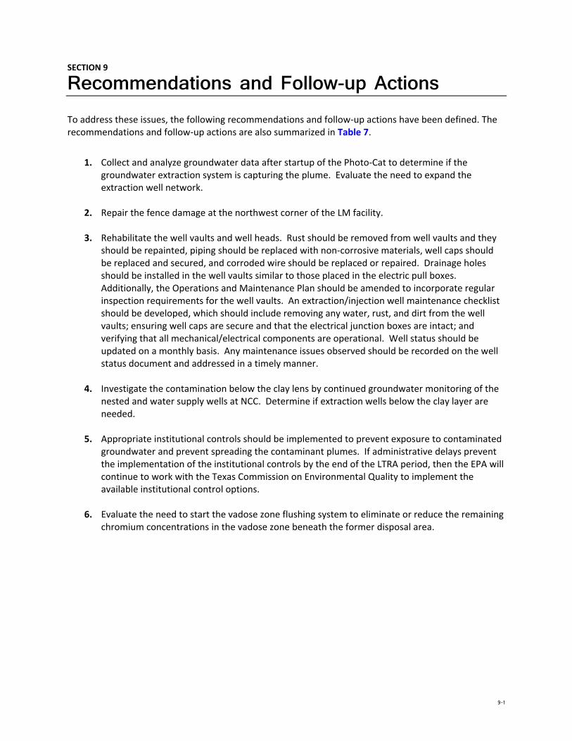
SECTION 9
Recommendations and Follow-up Actions To address these issues, the following recommendations and follow‐up actions have been defined. The recommendations and follow‐up actions are also summarized in Table 7.
1. Collect and analyze groundwater data after startup of the Photo‐Cat to determine if the groundwater extraction system is capturing the plume. Evaluate the need to expand the extraction well network.
2. Repair the fence damage at the northwest corner of the LM facility.
3. Rehabilitate the well vaults and well heads. Rust should be removed from well vaults and they should be repainted, piping should be replaced with non‐corrosive materials, well caps should be replaced and secured, and corroded wire should be replaced or repaired. Drainage holes should be installed in the well vaults similar to those placed in the electric pull boxes. Additionally, the Operations and Maintenance Plan should be amended to incorporate regular inspection requirements for the well vaults. An extraction/injection well maintenance checklist should be developed, which should include removing any water, rust, and dirt from the well vaults; ensuring well caps are secure and that the electrical junction boxes are intact; and verifying that all mechanical/electrical components are operational. Well status should be updated on a monthly basis. Any maintenance issues observed should be recorded on the well status document and addressed in a timely manner.
4. Investigate the contamination below the clay lens by continued groundwater monitoring of the nested and water supply wells at NCC. Determine if extraction wells below the clay layer are needed.
5. Appropriate institutional controls should be implemented to prevent exposure to contaminated groundwater and prevent spreading the contaminant plumes. If administrative delays prevent the implementation of the institutional controls by the end of the LTRA period, then the EPA will continue to work with the Texas Commission on Environmental Quality to implement the available institutional control options.
6. Evaluate the need to start the vadose zone flushing system to eliminate or reduce the remaining chromium concentrations in the vadose zone beneath the former disposal area.
9-1

SPRAGUE ROAD GROUNDWATER PLUME SUPERFUND SITE SECOND FIVE-YEAR REVIEW REPORT
This page is intentionally left blank.

SECTION 10
Protectiveness Statement The selected remedy remains protective in the short‐term since residents are not currently exposed to contaminated drinking water via private water supply wells. The groundwater extraction system was constructed in accordance with the requirements of the ROD, and extraction, treatment, and monitoring of the groundwater was being conducted as required. However, the groundwater recovery system has been inoperable since December 2010 during the procurement and installation of a new water treatment system (Photo‐Cat). The Photo‐Cat system has been installed and start‐up activities are underway. Therefore, a determination that the groundwater remedy is still performing as intended cannot be made at this time until after the Photo‐Cat treatment system is fully operational and the groundwater extraction system capture zones can be determined relative to the contaminant plume boundaries. These actions are expected to take approximately 12 to 18 months to complete, at which time an addendum to this Five‐Year Review report will be prepared assessing the performance of the groundwater remedy.
10-1

SPRAGUE ROAD GROUNDWATER PLUME SUPERFUND SITE SECOND FIVE-YEAR REVIEW REPORT
This page is intentionally left blank.

SECTION 11
Next Review A Five‐Year Review Report Addendum will be prepared in the next 12 to 18 months.
11-1

SPRAGUE ROAD GROUNDWATER PLUME SUPERFUND SITE SECOND FIVE-YEAR REVIEW REPORT
This page is intentionally left blank.

SPRAGUE ROAD GROUNDWATER PLUME SUPERFUND SITE SECOND FIVE-YEAR REVIEW REPORT
Tables

SPRAGUE ROAD GROUNDWATER PLUME SUPERFUND SITE SECOND FIVE-YEAR REVIEW REPORT
This page intentionally left blank.

TABLE 1
Chronology of Site Events
Date Event
12 April 1996 Site discovery
April 1996 through May 1998
NPL responsible party search
March 1997 Preliminary assessment
20 March 1997 Site Inspection completed
28 March 1997 Hazard Ranking System scoring completed
1 April 1997 Proposed for inclusion on NPL
September 1997 through September 2000
RI/FS performed
25 September 1997 Final NPL listing
January 1999 through February 2000
Removal action
August 2000 through September 2002
Remedial design
29 September 2000 ROD issued
September 2000 through November 2000
Removal action
September 2002 through September 2003
Remedial action construction
20 September 2002 Final Design Report submitted
15 September 2003 RA Report submitted
29 September 2003 Preliminary Close Out Report completed
28 June 2004 Operation and Maintenance Plan submitted
29 September 2004 Remedy is Operational and Functional
30 September 2004 LTRA activities initiated
January 2005 Annual Operating Report submitted
February 2005 Quarterly Ground Water Monitoring Report for December 2004 sampling event submitted
May 2005 Quarterly Ground Water Monitoring Report for March 2005 sampling event submitted
March 2006 Annual Operating Report submitted
January 2007 Quarterly Ground Water Monitoring Report for October 2006 sampling event submitted
1-1

Date Event
April 2007 Quarterly Ground Water Monitoring Report for February 2007 sampling event submitted
April 2007 Semi‐Annual Operating Report submitted
July 2007 Quarterly Ground Water Monitoring Report for May 2007 sampling event submitted
October 2007 Annual Operating Report submitted
October 2007 Quarterly Ground Water Monitoring Report for August 2007 sampling event submitted
March 2008 Quarterly Ground Water Monitoring Report for November 2007 sampling event submitted
April 2008 Semi‐Annual Operating Report submitted
May 2008 Quarterly Ground Water Monitoring Report for March 2008 sampling event submitted
September 2008 Quarterly Ground Water Monitoring Report for July 2008 sampling event submitted
October 2008 Annual Operating Report submitted
February 2009 Ground Water Monitoring Report for December 2008 sampling event submitted
April 2009 Semi‐Annual Operating Report submitted
July 2009 Ground Water Monitoring Report for May 2009 sampling event submitted
October 2009 Annual Operating Report submitted
December 2009 Ground Water Monitoring Report for October 2009 sampling event submitted
April 2010 Semi‐Annual Operating Report submitted
July 2010 through December 2010
In situ pilot test was performed to evaluate effectiveness of an alternative remedy
October 2010 Annual Operating Report submitted
November 2010 Ground Water Monitoring Report for August 2010 sampling event submitted
12 December 2010 Ion exchange system (remedy) was shut down due to the inability to obtain an acceptable contract extension with the ion exchange system vendor
11 January 2011 Ion exchange (remedy) system was removed from the site.
February 2011 In situ Pilot Test Results Report submitted
22–31 March 2011 Phase I of the Photo‐Cat pilot testing was performed
April 2011 Semi‐Annual Operating Report submitted
June 2011 Ground Water Monitoring Report for April 2011 sampling event submitted
1-2
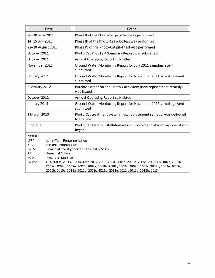
Date Event
28–30 June 2011 Phase II of the Photo‐Cat pilot test was performed
14–15 July 2011 Phase III of the Photo‐Cat pilot test was performed
22–28 August 2011 Phase IV of the Photo‐Cat pilot test was performed
October 2011 Photo‐Cat Pilot Test Summary Report was submitted
October 2011 Annual Operating Report submitted
November 2011 Ground Water Monitoring Report for July 2011 sampling event submitted
January 2012 Ground Water Monitoring Report for November 2011 sampling event submitted
3 January 2012 Purchase order for the Photo‐Cat system (new replacement remedy) was issued
October 2012 Annual Operating Report submitted
January 2013 Ground Water Monitoring Report for November 2012 sampling event submitted
1 March 2013 Photo‐Cat treatment system (new replacement remedy) was delivered to the site
June 2013 Photo‐Cat system installation was completed and started‐up operations began.
Notes: LTRA Long ‐Term Response Action NPL National Priorities List RI/FS Remedial Investigation and Feasibility Study RA Remedial Action ROD Record of Decision Sources: EPA 2000a, 2008a; Tetra Tech 2002, 2003, 2004, 2005a, 2005b, 2005c, 2006; EA 2007a, 2007b,
2007c, 2007d, 2007e, 2007f, 2008a, 2008b, 2008c, 2009a, 2009b, 2009c, 2009d, 2009e, 2010a, 2010b, 2010c, 2011a, 2011b, 2011c, 2011d, 2011e, 2011f, 2012a, 2012b, 2013.
1-3

TABLE 2
Contaminants of Concern Media Contaminant Concentration Range
Surface soils Chromium 151 – 8,040 mg/kg
Vadose zone Chromium 1.6 – 1,170 mg/kg
Ground water Chromium 0.270 – 11.2 mg/L
1,1‐DCE 0.007 – 0.009 mg/L
Notes:
mg/L Milligram per liter mg/kg Milligram per kilogram 1,1‐DCE 1,1‐dichloroethene
Source: EPA 2000a
2-1

TABLE 3
Remedial Goals Media Contaminant Remedial Goals
Vadose zone Chromium 1.0 mg/kg
Ground water Chromium 0.1 mg/L (100 µg/L)
1,1‐DCE 0.007 mg/L
Notes:
mg/L Milligram per liter mg/kg Milligram per kilogram µg/L Microgram per liter 1,1‐DCE 1,1‐dichloroethene Source: EPA 2000a
3-1

TABLE 4
Schedule for Long-Term GroundwaterMonitoring
Year
Number of Ground Water Sampling
Events Comments
2000 1
2001 1
2002 2
2003 3 Ground water treatment system was completed.
2004 3
2005 2
2006 1
2007 4
2008 3
2009 2
2010 1 Ground water treatment system was shut down on 12 December 2010.
2011 3
2012 1
2013 1 Two more sampling events are planned this year.
4-1

TABLE 5
Actions Taken Since the Last Five-Year Review
Issues From Previous Review
Recommendations/Follow‐up Actions
Party Responsible
Milestone Date
Action Taken and Outcome Date of Action
Corrosion of electrical components in the well vaults.
Complete maintenance and repair work on the electrical components for the ground water extraction and injection network. The installation of Coyote Pump Protectors, drainage holes in electrical pull boxes, and replacement of corroded electrical components should be completed as planned.
EPA In progress Coyote pump protectors were installed, drainage holes were drilled in the electrical pull boxes, and corroded electrical components were replaced. However, the condition of the recovery and injection wells have deteriorated during the time the treatment system has been down. Standing water was observed in some of the well vaults, pipe and vaults were rusty, the electric junction boxes in the vaults were open and contained water, rust, and dirt, the well caps were not in place on many of the wells, some of the concrete pads were cracked or damaged, and some of the electrical wires were loose or corroded.
Ongoing
5-1

Issues From Previous Review
Recommendations/Follow‐up Actions
Party Responsible
Milestone Date
Action Taken and Outcome Date of Action
Increasing trend of chromium concentrations at select recovery wells in the NCC extraction system
Expand the ground water monitoring network near the leading edge of the NCC chromium plume. Additional data is needed to assist in evaluating the changes in chromium concentrations recorded in select recovery wells.
EPA 2010 22 additional nested monitoring wells were installed near the leading edge of the NCC chromium plume. These well are included in the ground water monitoring program. Sampling of the first set of wells indicated that the chromium plume had migrated further downgradient. The second sets of wells were installed in 2013 and were sampled in June 2013.
2011 (10 nested wells) and
2013 (12 nested wells)
Improve the capture Complete the development of a EPA 2008 Annual Updated ground water model was 2008 Annual zone evaluation for the replacement ground water model to O&M Report developed and included in the 2008 O&M ground water improve the capture zone evaluation for Annual O&M Report. The ground Report extraction system. the ground water recovery system.
Development of the new models is currently underway and is expected to be completed in time for the 2008 Annual Operation and Maintenance Report.
water model was updated again in October 2010 and included in the 2010 Annual O&M Report.
The use of institutional Identify available institutional controls EPA 2010 The EPA/TCEQ are currently Ongoing controls to protect the to protect the remedy effectiveness and evaluating the administrative remedy effectiveness prevent accidental exposure via private
wells installed through the contaminated portion of the aquifer
requirements for implementing the ICs at the site.
5-2

Issues From Previous Review
Recommendations/Follow‐up Actions
Party Responsible
Milestone Date
Action Taken and Outcome Date of Action
Minor repairs to monitor wells
Perform maintenance and repair work on the Site monitor wells. The locks should be replaced on all conventional monitor wells in order to prevent unauthorized access to the wells. The expansion plugs and PVC well caps should be replaced where necessary to prevent surface water infiltration into the monitor wells. The O‐rings on the well vault lids should be replaced where necessary to prevent surface water infiltration into the well vaults.
EPA 2009 Maintenance and minor repair work, including installing new pad locks, expansion plugs, PVC well caps and gaskets on the well vaults were completed to the monitor wells in 2009. However, during the site inspection monitoring wells needing minor repair were observed.
Ongoing
Improve Public Outreach
Increase the frequency of public updates concerning the sampling results and the progress of the remedy.
EPA Ongoing Sample results are provided to landowners upon request. Local system operator maintains regular communication with numerous businesses and residences in the area.
Ongoing
5-3

TABLE 6
Issues Identified
Issues
Affects Current Protectiveness
(Yes/No)
Affects Future
Protectiveness
(Yes/No)
Ground water plume migration— The ground water data and model indicate that the plumes at all three release areas (M&C, LM, and NCC) have migrated downgradient.
No Yes
Fence damage— The northwest corner of the LM facility has minor fence damage.
No No
Well maintenance— The condition of the recovery and injection wells has deteriorated during the time the treatment system has been down. Standing water was observed in some of the well vaults; pipe and vaults were rusty; electric junction boxes in the vaults were open and contained water, rust, and dirt; well caps were not in place on many of the wells; some of the concrete pads were cracked or damaged; and some of the electrical wires were loose or corroded. Additionally, some of the monitoring wells needed minor repairs.
No Yes
Vertical contaminant migration— Concentrations above and below the clay lens in the NCC nested monitoring wells and water supply wells indicate possible vertical migration of contaminants.
No Yes
Institutional Controls— Appropriate institutional controls to prevent the installation of water supply wells in or downgradient of the contaminant plumes have not been implemented.
No Yes
Vadose zone flushing system— The vadose zone flushing system installed based on the remedy selected in the ROD has never been operated.
No Yes
6-1

TABLE 7
Recommendations and Follow-Up Actions
Issue
Recommendations and
Follow‐up Actions Party
Responsible Oversight Agency
Milestone Date
Affects Protectiveness
(Yes/No) Current Future
Ground water plume migration
Collect and analyze ground water data after startup of the Photo‐Cat to determine if the ground water extraction system is capturing the plumes. Evaluate the need to expand the extraction well network.
EPA State September 2014 No Yes
Fence damage Repair the fence damage at the northwest corner of the LM facility. EPA State September 2013 No No
Well maintenance
Rehabilitate the well vaults and well heads. Rust should be removed from well vaults and they should be repainted, piping should be replaced with non‐corrosive materials (iron rust from corroded pipes could affect the Photo‐Cat efficiency), well caps should be replaced and secured, and corroded wire should be replaced or repaired. Drainage holes should be installed in the well vaults similar to those placed in the electric pull boxes. Additionally, the Operations and Maintenance Plan should be amended to incorporate regular inspection requirements for the well vaults. An extraction/injection well maintenance checklist should be developed, which should include removing any water, rust, and dirt from the well vaults; ensuring well caps are secure and that the electrical junction boxes are intact; and verifying that all mechanical/electrical components are operational. Well status should be updated on a monthly basis. Any maintenance issues observed should be recorded on the well status document and addressed in a timely manner
EPA State Ongoing No Yes
Vertical contaminant migration
Investigate the contamination below the clay lens by continued ground water monitoring of the nested and water supply wells at NCC. Determine if extraction wells below the clay layer are needed.
EPA State September 2014 No Yes
7-1

Issue
Recommendations and
Follow‐up Actions Party
Responsible Oversight Agency
Milestone Date
Affects Protectiveness
(Yes/No) Current Future
Institutional controls
Appropriate institutional controls should be implemented to prevent exposure to contaminated ground water and prevent spreading the contaminant plumes. If administrative delays prevent the implementation of the institutional controls by the end of the LTRA period, then the EPA will continue to work with the Texas Commission on Environmental Quality to implement the available institutional control options.
EPA/State EPA/State September 2014 No Yes
Vadose zone flushing system
Evaluate the need to start the vadose zone flushing system to eliminate or reduce the remaining chromium concentrations in the vadose zone beneath the former disposal area.
EPA State September 2014 No Yes
Notes: EPA U.S. Environmental Protection Agency, Region 6 IC Institutional control TCEQ Texas Commission on Environmental Quality
7-2

SPRAGUE ROAD GROUNDWATER PLUME SUPERFUND SITE SECOND FIVE-YEAR REVIEW REPORT
Attachment 1 Figures

SPRAGUE ROAD GROUNDWATER PLUME SUPERFUND SITE SECOND FIVE-YEAR REVIEW REPORT
This page intentionally left blank
.

< << <
M-29
<<
<<
<<
<<
<<
<<
<<
<<
<<
<<
<<
<<
<<
<<
<<
<<
<<
NOLAN STREET
HILLMONT ROAD
83RD STREET
BE
ES
ON
AV
EN
UE
81ST STREET
OREGON STREET
STEVEN ROAD
SP
RA
GU
ER
OA
D
MA
RY
FR
AN
CIS
AV
EN
UE
GREENFIELD ACRES
N-7
N-7R
MMW-09
NMW-10
NRW-21
NRW-08
MACHINE AND CASTING
LEIGH METAL
CHROOMIUM
<<
M-28
<<M-22
M-24
<<
<<
<<
M-23
<
<
M-35 < M-9
<M-8M-6
<
<
<<<
< MIW-05
MIW-06
<<
MMW-02
<<M-38<<
MRW-04
<<
<
MIW-04MIW-03
<
<< M-4
< M-5 < <<
<<
MRW-05MRW-03
MMW-05 M-25
MMW-07M-3
<
<<
M-1R
MMW-04
< <<<
!!!!!(<
((((MRW-02
!!!!!(((((
< <
<<<<
<<
< <<<
<< M-7MMW-06
<<MMW-03 <
See Inset
M-15
<
M-39M-1
<< << !!!!!(((((!( <
<MMW-10(< !!!!((((
MRW-01
! MRW-06
MIW-02 M-21!<(
<<
<
( <
< !!(<(!(!!!!!(<
<<
<
(((
!!!!(((<!!!(((( < MRW-07
MIW-01 <
MMW-01
<
MMW-08
<< M-2MDW-01
M-18
<<
<
M-27< M-10 <
<
M-16 M-17
<< <<
M-20 <<
< <M-14 <
<
<<
<<
<<
M-37
M-40 LMW-13
<<
M-11
<< <<
M-41 M-19
M-36
< <M-32 <
< M-33 LRW-25
M-12 M-31 <
< <
<M-30
L-20 LMW-17<<
LMW-16<<
<
< <
<
<<
<
LRW-16
<
<<
LRW-24 L-27
<<
L-5M-13 <<
<<
LRW-17 <<L-19 LRW-19
<<
<<
LRW-18
L-21
< L-2
<
<<
LRW-15
L-4
LRW-13
MIW-07
<
<
<< <
<
LMW-12 <
<
< L-18
<
PZ-2<<LRW-14
L-1
L-23<<
<<!( LMW-09
<<
<
<
<
<
<
<
L-7
L-6 <
<
LRW-03 <
< LIW-09
LMW-05L-16 <
PZ-1
<
<
< <<< LRW-12 <
LRW-20
LRW-01 LMW-19
L-28<
<
L-11<
<
< LRW-21<
< <
<<<<
< LMW-14
LRW-22
<
!(
<<L-26
<<
<
<
<
<
LMW-06
<
LRW-06
L-12
<<
<
LRW-05
LMW-15LRW-02
<<
L-13LRW-04
<
<
<
LRW-11 <
<<
L-10 < <<
<< <
<LRW-23
<
MIW-08 < << <
LRW-08 LMW-10
<< L-9
<<
<
<
<
<
<
<
<LRW-27 L-25
< <
L-15 LRW-10L-14
<<<< <
L-8LIW-06 <<
LRW-07
<<
LMW-07
<<!(< !(
<
<
<
<<
<PZ-4
PZ-3< < <
LMW-01
<<LMW-11
<LIW-01 <LIW-04
LRW-09
<<<
<LIW-07
W-05
LMW-18LIW-02
< LMW-04
<LIL-22<< LRW-26<<
L-24
<
LMW-03
<
<<
LIW-03 NIW-16LMW-02
< <
<
<
<
<
<
NIW-19 <LMW-08
NIW-17
NIW-18 <
<
<
<
NIW-20
NMW-04
NIW-21
<
<
<< <
<
<
<
< <
W-02
<
<NDW-01
W-03 <
NIW-22 <<
NMW-02
<
<
<
<W-06
NIW-04
NIW-23 NI <<
NINIW-05
NIW-01NIW-24 <<
NIW-08
<
<
<
NIW-25 <NMW-01
NMW-08
<< <
<
<
< <
<<
<<NRW-02
NRW-05 << <
<<NMW-14 <<
NMW-13 NMW-05
NRW-06
NI <<
NRW-19
NRW-10
<
<
<
W-26 <
NRW-01
NRW-16
< <<
<NRW-11NIW-12
NATI NALNI <
NIW-07 NIW-11
<
<
<
<NMW-03
<W-10
< NRW-07
NMW-16NMW-09<
<< <
NRW-12
<<<
NNIW-09 <
NMW-07
<
<
<
NRW-17
NRW-18<
I
<
<
<
< <<
<
<
<<<
<
< < <
NMW-15 <NIW-15
< W-14
NMW-06 N-5NMW-18
< N-8
<
<<<
< NRW-20
NIW-27
<<< N-16<<
<<<<
NMW-23
NMW-24
< << <NRW-03
NRW-04
< <
<<
<<
<<
NMW-19
NRW-13
<<
<<
<<
<
<
<<
<<<NMW-26
<<
<NMW-28
<< <
N-14 <
<< <
<
<
<
<
< <
<
<<<<N-6
N-3 <NIW-13
NRW-22
NMW-27<< <NI < <
<<
<<
<<NMW-20 N-11
<
<
<
<<
< NRW-14<
NMW-17 < <NMW-11 <
NRW-24
N-12
N-17
NMW-25<
<<
<
NRW-23 < <
NMW-12
NRW-09
< <
< <
<
<< <
<< NMW-21
< < N-4
<<
N-2
<
< < < < NMW-22<<
<N-10<
<
<
< N-13
<<
<<
<
<
<
MMW-10 <A-7A-10
<
MRW-01
MRW-03
<
<
<<
<
<
C-5 C-6
M-1 C-2 !(!!(!(( !(
C-8< B-10 B-7
B-8 !!(!!((!( C-4
<
MMW-05
B-3 MRW-02 C-3( !(
C-1!(B-6 !(!!!(((
C-7B-2 !(
B-5MMW-04MRW-06 !(
B-4A-3
!!((<!(!( !(B-1 !!((B-9A-6 !(
<<!( !(
D-2 D-4 A-2 !( !(
M-2
<
D-3 !( A-5!
A-1(
<
MRW-07
201
3 -0
6-2
4 R
:\F
ed
era
l\EP
A\R
AC
II\0
00
7-S
pra
gu
e R
d\G
IS\M
XD
s\1
1X
17
_S
pra
gue
Fig
01
201
30
1.m
xd
EA
-Da
llas
jsch
wer
tz
<
<
<
A-4 MDW-01 <
!(D-1 !( <<
MMW-03
!!!(((A-9
Ñ SPRAGUE ROAD SUPERFUND SITE
LEGEND: ODESSA, TEXAS Private Well
<<
<<
<
<
!( Piezometer
Image Source: TNRIS Texas Orthoimagery Project, 2009.Inset: GoogleEarth Pro, 2012
FIGURE 1SITE LAYOUT
WELL LOCATION MAP
Drinking Well
Monitor Well
Recovery Well PREPARED FOR: BY:
<<<
<
!( Pilot Test Well
200 100 0 200 400 Injection Well
Feet

<
<
<
<
<
<
<
<
<
<
<
<
<
<
<
<
<
<
<
<
<
<
<
<
<
<
<
<
<
<
<
<
<
<
<
<
<
<<
<
<
<
<
<
NOLAN STREET
HILLMONT ROAD
BE
ES
ON
AV
EN
UE
81ST STREET
OREGON STREET
STEVEN ROAD
SP
RA
GU
ER
OA
D
MA
RY
FR
AN
CIS
AV
EN
UE
GREENFIELD ACRES
2885
2880
2870 2875
2865
2880
2885
2875
2880
2875
2885
2880
2870
2885
28802875
2882
2881 2884
2883
2885
2880
<<
< <
<
<<
<<
A-7
<<
<<
<
<
<<
< C-62880.27
C-8b* 2880.53 C-8a
2880.55B-10b*
2881.84 B-72881.97
C-2 !(!!((!(C-!5(
2880.61 2880.16B-10a
2881.90 B-82881.94
C-42880.58<< B-3 !!!!(((( !(
A-10b* 2884.40
C-32880.51
!( <2881.99 ! B-6B-2 !(
(2881.61
2882.01
<
C-1 !(!!(!((
2879.60A-10a
2884.50 C-7a2880.46B-4
2881.92B-5 !(
2882.12 C-7b* 2880.48
D-42885.10<<
!!!(((
A-32884.90
!!(!!((( <
<
<
<
<<
< <
<
<<
<<<
<MMW-092882.46
< <
<2884.60
A-62884.16
<<
!(B-12882.13
<< B-9aA-2 !(
2884.81
!(D-2
2885.35
!( 2881.97
B-9b* 2881.95
!( A-5
<<
(! 2884.55( A-4D-3
!
< 2884.452884.96<D-12885.54
<
<
<
<
!(
<<
<<
Test AreaPil!!!(!((
A-1(
2884.72 otMMW-022875.68
<A-9a2884.49
<
<<
< <
A-9b* 2883.69<
<
< << <
<
<
<< <
MMW-07
<< 2871.66 <<
<
<
MMW-05<2879.28
!!!!!(((((
<
<
<MMW-10!!!!!(((((!<(!(2882.86
<
< << <MMW-06
< 2875.94
!(!!!!((((
< <
<<( !!!!<((( <!(!(MMW-04(! 2884.59
< !(
!!!!(((( <
M-22882.61<
<
<
< !!((<
!!<<
<
(( < <
<
MMW-08< 2886.14
< <
MMW-03<< 2874.93!!!!(((( <
<
<
<<
<
<
MMW-012885.23
< <<
<<
<<
< <<
< <
< <
<
83RD STREET
<
<
<
< <<LMW-13
<< 2862.73
<
<
<
<<
< <
<
<<
LMW-16< 2865.00
<<
< <
<
<
< <
<
LMW-17
<< 2863.47
<
<
<
<
<<
<
<
<< <
PZ-2 <
<<!( 2868.82
<
<
<
<
<
<< <
<
< <
LMW-12 < << 2874.42
<<
<<
<
< <
<
<
<
<
<
<
<
<
<<
<
<
<
<
<
<
<
<
<
<
< <
<
<
< <LMW-18!! <((< 2884.76
< LMW-01
< < <2885.09
L-24<<2892.08
<
<
LMW-09<2869.09 <
< < <
<
<<
<
<
<
LMW-14 <
< < 2871.78 <
<
<
<
<
< LMW-05< 2870.92<
PZ-12868.53
<<
<
<
<
<
<<
<
<
<
<
LMW-06< < 2878.60 <
!(
<
<
<
<
LMW-15
<< 2867.42LMW-192872.24
<<
<
<
< <
<<
< <
<LMW-11
< 2871.62
<<
LMW-10
<< 2862.81
<
<<
LMW-04< 2875.75
<
<< <
LMW-072883.97
<
< L-15
2885.53 < <
< <<< L-22
2882.56
<
<
<
<
<
<
<
<
< <
NMW-04< < 2878.77
<
<
<
<
<
<
< <
<<
<
<
<
<
< <
<
<<
<
< <
< <
<
< < <
<
< <<
< << <NMW-05< < 2878.92
<<
NMW-022881.14
<
NMW-08< 2878.55
NMW-012882.54
<
<<
<
<
< <<
<
<
< <<
< NMW-14* 2880.95
<
<
< <
NMW-07< <
2879.55
<
NMW-132880.04<
<<
*
<
<
<
<
NMW-16<2876.49
<NMW-102876.80
<
<
<
<
<
<
<
<
NMW-03< <2879.02
<
NRW-082876.30
<<<
< <
<<<
< NMW-09<<2877.60
<
<28
75
<
NMW-062873.84
<<
< <
<
<
<
<
<
<<
<<
<<
< <
< <<
<
<< < <
<<
NMW-17 NMW-19b* 2874.36 2870.50
<NMW-11<2873.76 <<
* <<NMW-18a2871.45
<
<
<<
<
<
<
<
<
<
< <NMW-15< 2877.29
<
< <
< <
< NMW-12< 2875.22
NMW-18b* 2871.16
NMW-19a2871.62
<
NMW-20a2870.57
<
<<
NMW-20b* 2869.92
2013
-0
1-2
1 R
:\Fe
dera
l\EP
A\R
AC
II\0
007-
Sp
rag
ue R
d\G
IS\M
XD
s\11
X17
_S
pra
gu
e201
211W
ate
rLe
vels
.mxd
E
A-D
alla
s js
chw
ertz
<<
< <
< <<
<<
< <<
LEGEND SPRAGUE ROAD SUPERFUND SITE < ODESSA, TEXAS <
NMW-22a2872.72<<<<
NMW-22b* 2872.77
NMW-21a2870.46
NMW-21b* 2870.50
Ñ Private Well
Note:* Well
Drinking Well s NMW-10, NMW-14, NMW-16, NMW-18b, NMW-19b,
NMW-20b, NMW-21b, and NMW-22b were screened FIGURE 2n POTENTIOMETRIC SURFACE
Monitor Well<<
!( Piezometer below the silty/sandy clay zone, and not included idet ing potentiometric surface. NOVEMBER 2012erminLMW-11
2887.68 Well Identifier LabelRecovery Well
<<<
<
! Pilot( Test Well
Ground Water ElevationInjection Well160 80 0 160 320
PREPARED FOR: BY:Feet

<<
<<
<<
<<
<<
<< <<
S
<<
<<
<<
<<
<<
<<
<<
<<
<<
<<
<<
<<
<<
<<
<<
<<
<<
<<
<<
NOLAN STREET
HILLMONT ROAD
BE
ES
ON
AV
EN
UE
81ST STREET
OREGON STREET
STEVEN ROAD
SP
RA
GU
ER
OA
D
MA
RY
FR
AN
CIS
AV
EN
UE
GREENFIELD ACRE
14.3
21.0
C-8a MMW-0516.1 115 <<
<<
D-221.3
C-8b<<
<
<<
<
MMW-0954.8
!!!37.9 ( !(((A-10b
<22.5 <
!(
MMW-04A-10a 14.31,330<<
!!!(!(((
<< !(!(MRW-06
2,500 MMW-101,830 J
!( !!!(((A-7<52.3 <
!(!(
<
< MRW-01179
<
<
!(
<<
D-4111
M-1R10.0 U
((!!!(<<<< A-61,090 J
C-7b
<<
<<
!( !!!(((!(M-537.8
!( A-2 !(
45.4 !(!( C-7a
10.0 U
<<
<<
<< MMW-07
261
<<
<<
<<
M-3973.2
<<
< <<
<<
<<<<
< <<
< MRW-01
<<
< < <
179
< <M-2
<<
!(
< <
M-2139.3
<<M-25
28.0 !( !( A-5257 M-2
35.2 JMMW-04
A-423.4
<
MMW-05115
< <
MRW-071,690
< D-3548
!!!(((!(
A-9a11.7
<
MRW-062,500
<
< << <
MMW-06648
<
<<
< <
<
<35.2 J <
<< <
< <
<
<
<< <
<
<<
<<
<
< <
<<
<
< <
<
<
<< <
< <
MMW-101,830 J
M-710.0 U D-1
369 A-9b75.3
<<
<
<
MRW-071,690
<
M-1010.0 U<
<
<<
< MMW-01664
<<
<<
<<
<
<<
<
<
<
<
<
83RD STREET
<<
<<
<
<
L-19
<<127
<<
<
<
LMW-1710.0 U
<<<
<
L-5144
<< <
<
<
<
<< <
<
<
<<<
<
<< <
< <
<
<< <
<<!( <
<
<
<
<
<
< << <
<<
<< <
<<
<<<< <
<
<< <
<< <
<< <
< <
<<
<< <
< L-8 < <
< 95.0
< <
<
<
<
<
<
< <
< <
LMW-16236
L-2710.0 U
<<
<
<
<
<
<<
<
<<
<<
<
<
< <LMW-12 <
92.4 <
<
<
<
< <
< < < <
L-446.7
L-18< 179<LMW-09
74.2
<<
PZ-171.0
<<
<<
!(
LMW-15<
30.3
<<
<
<<
<<
<
<<
<
!(< !( <
<
< <
<
< <<
<<
<
<
<
<
<
< <
< <
<
<
<<
<
< <
LMW-0731.2
<< <
<
L-22523
<
<<
<<
<<
<< <
<<
<<
<<
<<
< <
< <
< <
<
< <<
< <
< <<
< NMW-1413.7
<
<<
<
<<
<
<
<
<
< <NMW-03822
<
<
NMW-13149
<
<<
<
<<
<
< NMW-16< 62.4
NMW-09123
NMW-06 NMW-18a76.6 129
<< <
<
<
<
<
<<
<<
<<
<
< < < <
< <
<< < < NMW-10
428 < <
<
<<
<<
<< <
<<
<<
<
< <
<
<N-7R310
<<< < <<
NMW-111,160
<
<<
NMW-15207 <<
<
NMW-18b104
< <<
NMW-0728.0
NMW-19a1,410< <
<
<<<<
<N-3364
<<
<<
<
<
<
<
<
<
< <
< <
NMW-12604
< <
NMW-19b1,250
NMW-20a323
<<
NMW-20b72.5
<<
<<
< <
NMW-22a47.7
<<
< N-11< 96.1
<<
NMW-22b<< 27.1 NMW-21a
13.6
<<N-1068.4
<<<< NMW-21b22.6
<< N-1310.0 U
2013
-0
1-2
1 R
:\Fe
dera
l\EP
A\R
AC
II\0
007-
Sp
rag
ue R
d\G
IS\M
XD
s\11
X17
_S
pra
gu
eCo
nc_2
012-
Fig
3ne
w.m
xd
EA
-Dal
las
jsch
we
rtz
< <<<
: NOTES:
SPRAGUE ROAD SUPERFUND SITEODESSA, TEXAS
Ñ LEGEND
Private Well
<<
<<
<
<
!( Piezometer
CHROMIFIGURE 3
UM CONCENTRATIONS MAPNOVEMBER 2012
1. CONCENTRATIONS IN MICROGRAMS PER LITER.Drinking Well 2. () INDICATE DUPLICATE SAMPLE RESULTS.
3. DATA NOT CONTOURED SINCE RECOVERY WELLSWERE NOT SAMPLEDMonitor Well
Recovery Well PREPARED FOR: BY:
<<<
<
!( Pilot Test Well
160 80 0 160 320 Injection Well
Feet

SPRAGUE ROAD GROUNDWATER PLUME SUPERFUND SITE SECOND FIVE-YEAR REVIEW REPORT
Attachment 2 Documents Reviewed

SPRAGUE ROAD GROUNDWATER PLUME SUPERFUND SITE SECOND FIVE-YEAR REVIEW REPORT
This page intentionally left blank.
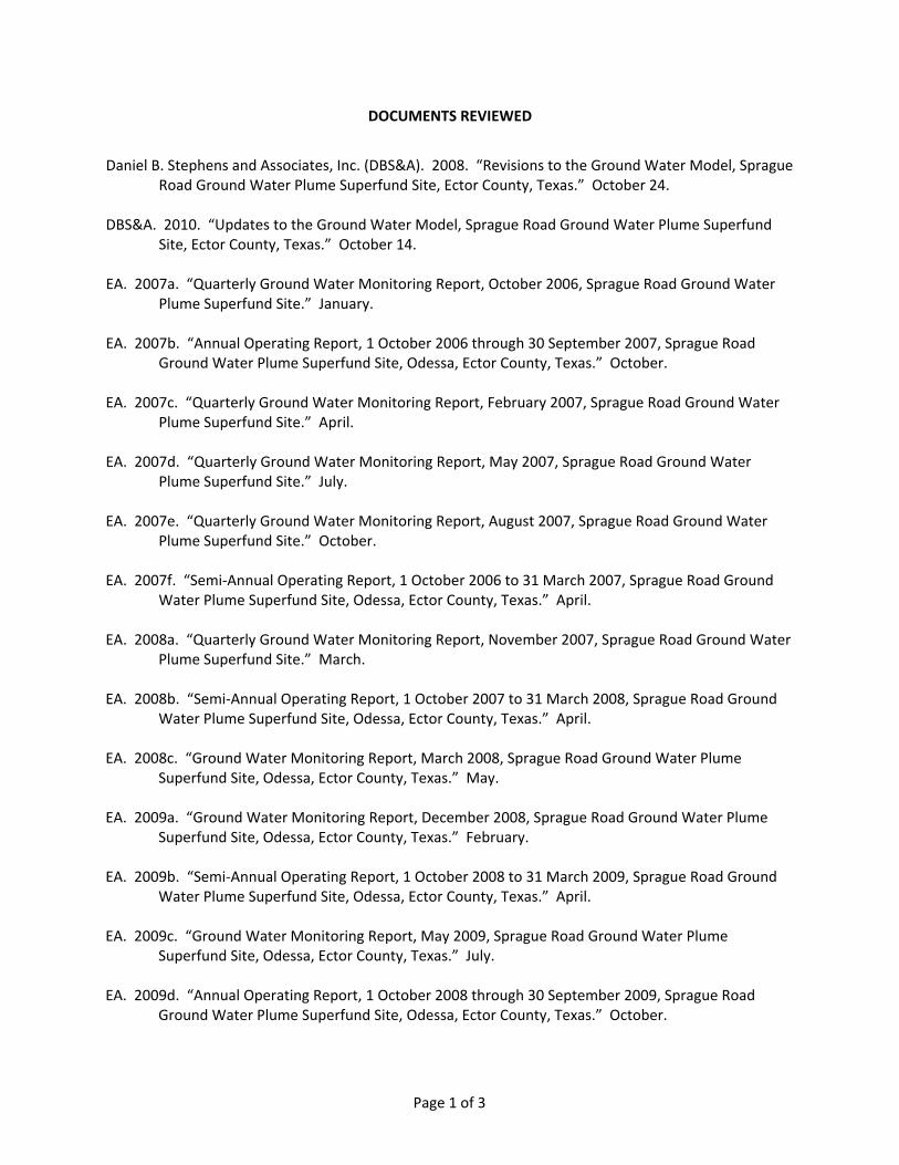
DOCUMENTS REVIEWED
Daniel B. Stephens and Associates, Inc. (DBS&A). 2008. “Revisions to the Ground Water Model, Sprague Road Ground Water Plume Superfund Site, Ector County, Texas.” October 24.
DBS&A. 2010. “Updates to the Ground Water Model, Sprague Road Ground Water Plume Superfund Site, Ector County, Texas.” October 14.
EA. 2007a. “Quarterly Ground Water Monitoring Report, October 2006, Sprague Road Ground Water Plume Superfund Site.” January.
EA. 2007b. “Annual Operating Report, 1 October 2006 through 30 September 2007, Sprague Road Ground Water Plume Superfund Site, Odessa, Ector County, Texas.” October.
EA. 2007c. “Quarterly Ground Water Monitoring Report, February 2007, Sprague Road Ground Water Plume Superfund Site.” April.
EA. 2007d. “Quarterly Ground Water Monitoring Report, May 2007, Sprague Road Ground Water Plume Superfund Site.” July.
EA. 2007e. “Quarterly Ground Water Monitoring Report, August 2007, Sprague Road Ground Water Plume Superfund Site.” October.
EA. 2007f. “Semi‐Annual Operating Report, 1 October 2006 to 31 March 2007, Sprague Road Ground Water Plume Superfund Site, Odessa, Ector County, Texas.” April.
EA. 2008a. “Quarterly Ground Water Monitoring Report, November 2007, Sprague Road Ground Water Plume Superfund Site.” March.
EA. 2008b. “Semi‐Annual Operating Report, 1 October 2007 to 31 March 2008, Sprague Road Ground Water Plume Superfund Site, Odessa, Ector County, Texas.” April.
EA. 2008c. “Ground Water Monitoring Report, March 2008, Sprague Road Ground Water Plume Superfund Site, Odessa, Ector County, Texas.” May.
EA. 2009a. “Ground Water Monitoring Report, December 2008, Sprague Road Ground Water Plume Superfund Site, Odessa, Ector County, Texas.” February.
EA. 2009b. “Semi‐Annual Operating Report, 1 October 2008 to 31 March 2009, Sprague Road Ground Water Plume Superfund Site, Odessa, Ector County, Texas.” April.
EA. 2009c. “Ground Water Monitoring Report, May 2009, Sprague Road Ground Water Plume Superfund Site, Odessa, Ector County, Texas.” July.
EA. 2009d. “Annual Operating Report, 1 October 2008 through 30 September 2009, Sprague Road Ground Water Plume Superfund Site, Odessa, Ector County, Texas.” October.
Page 1 of 3

EA. 2009e. “Ground Water Monitoring Report, October 2009, Sprague Road Ground Water Plume Superfund Site, Odessa, Ector County, Texas.” December.
EA. 2010a. “Semi‐Annual Operating Report, 1 October 2009 to 31 March 2010, Sprague Road Ground Water Plume Superfund Site, Odessa, Ector County, Texas.” April.
EA. 2010b. “Annual Operating Report, 1 October 2009 through 30 September 2010, Sprague Road Ground Water Plume Superfund Site, Odessa, Ector County, Texas.” October.
EA. 2010c. “Ground Water Monitoring Report, August 2010, Sprague Road Ground Water Plume Superfund Site, Odessa, Ector County, Texas.” November.
EA. 2011a. “Pilot Test Summary Report, Sprague Road Ground Water Plume Superfund Site, Odessa, Ector County, Texas.” February.
EA. 2011b. “Semi‐Annual Operating Report, 1 October 2010 to 31 March 2011, Sprague Road Ground Water Plume Superfund Site, Odessa, Ector County, Texas.” April.
EA. 2011c. “Ground Water Monitoring Report, April 2011, Sprague Road Ground Water Plume Superfund Site, Odessa, Ector County, Texas.” June.
EA. 2011d. “Photo‐Cat Pilot Test Summary Report, Sprague Road Ground Water Plume Superfund Site, Odessa, Ector County, Texas.” October.
EA. 2011e. “Annual Operating Report, 1 October 2010 through 30 September 2011, Sprague Road Ground Water Plume Superfund Site, Odessa, Ector County, Texas.” October.
EA. 2011f. “Ground Water Monitoring Report, July 2011, Sprague Road Ground Water Plume Superfund Site, Odessa, Ector County, Texas.” November.
EA. 2012a. “Ground Water Monitoring Report, November 2011, Sprague Road Ground Water Plume Superfund Site, Odessa, Ector County, Texas.” January.
EA. 2012b. “Annual Operating Report, 1 October 2011 through 30 September 2012, Sprague Road Ground Water Plume Superfund Site, Odessa, Ector County, Texas.” October.
EA. 2013. “Ground Water Monitoring Report, November 2012, Sprague Road Ground Water Plume Superfund Site, Odessa, Ector County, Texas.” January.
Purifics, ES Inc. (Purifics). 2013. Operations, Maintenance, Support, Installation Manual. February.
Tetra Tech. 2002. “Final Design Report, Sprague Road Ground Water Plume Site, Odessa, Texas.” September.
Tetra Tech. 2003. “Remedial Action Report, Sprague Road Ground Water Plume Superfund Site, Odessa, Texas.” September.
Page 2 of 3

Tetra Tech. 2004. “Ground Water Recovery, Treatment, and Injection System Operation and Maintenance Manual, Sprague Road Ground Water Plume Superfund Site, Odessa, Texas.” June.
Tetra Tech. 2005a. “Quarterly Ground Water Monitoring Report – December 2004, Sprague Road Ground Water Plume Superfund Site, Odessa, Ector County, Texas.” February.
Tetra Tech. 2005b. “Annual Report for Operation & Maintenance, October 1, 2003 to September 30, 2004, Sprague Road Ground Water Plume Site, Odessa, Ector County, Texas.” January.
Tetra Tech. 2005c. “Quarterly Ground Water Monitoring Report – March 2005, Sprague Road Ground Water Plume Superfund Site, Odessa, Ector County, Texas.” May.
Tetra Tech. 2006. “Annual Report for Operation & Maintenance, October 1, 2004 to October 19, 2005, Sprague Road Ground Water Plume Site, Odessa, Ector County, Texas.” March.
U.S. Environmental Protection Agency (EPA). 2000a. “Superfund Record of Decision, Sprague Road Ground Water Plume, Odessa, Texas.” EPA/ROD/R06‐00/513. September.
EPA. 2000b. “Institutional Controls: A Site Manager's Guide to Identifying, Evaluating and Selecting Institutional Controls at Superfund and RCRA Corrective Action Cleanups.” EPA 540‐F‐00‐005. September.
EPA. 2001. “Comprehensive Five‐Year Review Guidance.” EPA 540‐R‐01‐007. June.
EPA. 2007. “Gulf Nuclear Responses, 2005.” November. Online address: http://www.epa.gov/rpdweb00/rert/contaminatedsites.html. Accessed June 2008.
EPA. 2008. “First Five‐Year Review Report, Sprague Road Ground Water Plume Superfund Site, Odessa, Ector Country, Texas” September. Online Address: http://www.epa.gov/region6/6sf/texas/sprague/tx_sprague_1st‐5yr_review.pdf. Accessed June 2013.
EPA. 2013a. “Superfund Site Progress Profile – Sprague Road Ground Water Plume.” June. Online Address: http://cfpub.epa.gov/supercpad/cursites/csitinfo.cfm?id=0605023. Accessed June 2013.
EPA. 2013b. “Sprague Road Site Summary.” April. Online address: http://www.epa.gov/region6/6sf/pdffiles/sprague‐rd‐tx.pdf. Accessed June 2013.
Page 3 of 3

SPRAGUE ROAD GROUNDWATER PLUME SUPERFUND SITE SECOND FIVE-YEAR REVIEW REPORT
This page is intentionally left blank.

SPRAGUE ROAD GROUNDWATER PLUME SUPERFUND SITE SECOND FIVE-YEAR REVIEW REPORT
Attachment 3 Site Inspection Checklist

SPRAGUE ROAD GROUNDWATER PLUME SUPERFUND SITE SECOND FIVE-YEAR REVIEW REPORT
This page intentionally left blank.

FIVE-YEAR REVIEW SITE VISIT CHECKLIST
I. SITE INFORMATION
Site Name: Sprague Road Ground Water Plume Date of Inspection: 20-22 May 2013
Location and Region: Ector County, Texas EPA ID: TX0001407444
Agency, office, or company leading the five-year review:
EPA Region 6
Weather/temperature:
Sunny, windy /80°
Remedy Includes: (Check all that apply) Landfill cover/containment Groundwater pump and treatment Access controls Surface water collection and treatment Institutional controls Other (Monitored natural attenuation)
Attachments: Inspection team roster attached Site map attached (Figure 1 in Attachment 1)
II. INTERVIEWS (Check all that apply) Not Applicable
O&M Site Manager ___________________________ ________________________________
Name Title
Interviewed: by mail at office by phone Phone no. ________________ Problems, suggestions: Report attached (Attachment 5)
2. O&M Staff ___________________________ ____________________________________ Name Title
Interviewed: by mail at office by phone Phone no. Problems, suggestions: Report attached ________________________________________
____________________________________________________________________________
3. Local regulatory authorities and response agencies (i.e.; State and Tribal offices, emergency response office, police department, office of public health or environmental health, zoning office, recorder of deeds, or other city and county offices, etc.) Fill in all that apply.
Agency ____________________________________
Contact ___________________________ ____________________________________ Name Title
Interviewed: by mail at office by phone Phone no. Problems, suggestions: Report attached ________________________________________
____________________________________________________________________________
1

4. Other interviews (optional): Reports attached
Site interviews were not conducted during this Five-Year Review site visit. Due to the system being
nonoperational at the time of the visit, site interviews have been postponed to a later date. Interviews will be
included in a Five-Year Review Report Addendum that will be prepared in the next 12 to 18 months.
III. ON-SITE DOCUMENTS & RECORDS VERIFIED (Check all that apply)
1. O&M Documents O&M manual (O&M Work Plan) Readily available Up to date N/A
As-built drawings Readily available Up to date N/A Maintenance logs Readily available Up to date N/A
Remarks:
2. Site-Specific Health and Safety Plan Readily available Up to date N/A Contingency plan/emergency response plan Readily available Up to date N/A
Remarks:
3. O&M and OSHA Training Records Readily available Up to date N/A Remarks: ___O&M manual needs to be updated to incorporate Photo-Cat__________
4. Permits and Service Agreements Air discharge permit Readily available Up to date N/A
Effluent discharge Readily available Up to date N/A Waste disposal, POTW Readily available Up to date N/A Other permits Readily available Up to date N/A
Remarks:
5. Gas Generation Records Readily available Up to date N/A
6. Settlement Monument Records Readily available Up to date N/A
7. Groundwater Monitoring Records Readily available Up to date N/A
8. Leachate Extraction Records Readily available Up to date N/A
9. Discharge Compliance Records Air Readily available Up to date N/A Water (effluent) Readily available Up to date N/A
Remarks: Water effluent is tested daily for hexavalent chromium using a Hach® DR 2800™ Portable
Spectrophotometer field test kit. Test results are recorded in the daily reports.
10. Daily Access/Security Logs Readily available Up to date N/A Remarks: Site contractors and visitors are documented in the daily reports.
2
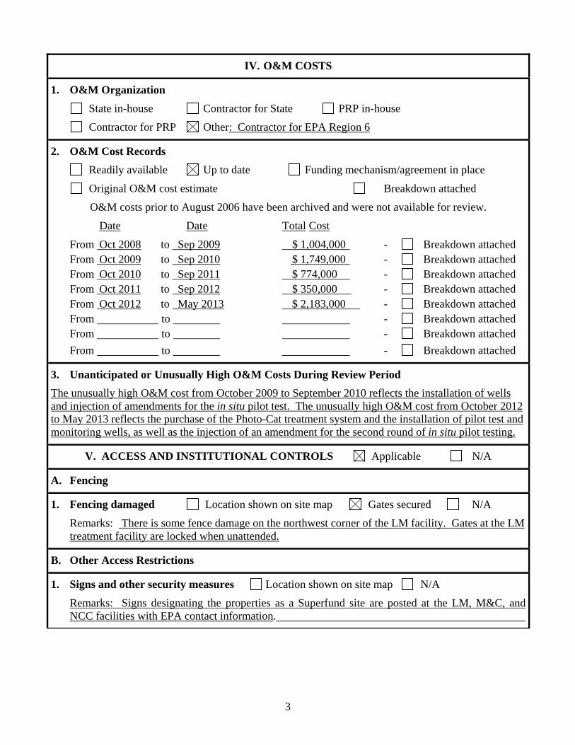
IV. O&M COSTS
1. O&M Organization
State in-house Contractor for State PRP in-house
Contractor for PRP Other: Contractor for EPA Region 6
2. O&M Cost Records
Readily available Up to date Funding mechanism/agreement in place
Original O&M cost estimate Breakdown attached
O&M costs prior to August 2006 have been archived and were not available for review.
Date Date Total Cost
From Oct 2008 to Sep 2009 $ 1,004,000 - Breakdown attached From Oct 2009 to Sep 2010 $ 1,749,000 - Breakdown attached From Oct 2010 to Sep 2011 $ 774,000 - Breakdown attached From Oct 2011 to Sep 2012 $ 350,000 - Breakdown attached From Oct 2012 to May 2013 $ 2,183,000 - Breakdown attached From to - Breakdown attached From to - Breakdown attached
From to - Breakdown attached
3. Unanticipated or Unusually High O&M Costs During Review Period
The unusually high O&M cost from October 2009 to September 2010 reflects the installation of wells and injection of amendments for the in situ pilot test. The unusually high O&M cost from October 2012 to May 2013 reflects the purchase of the Photo-Cat treatment system and the installation of pilot test and monitoring wells, as well as the injection of an amendment for the second round of in situ pilot testing.
V. ACCESS AND INSTITUTIONAL CONTROLS Applicable N/A
A. Fencing
1. Fencing damaged Location shown on site map Gates secured N/A
Remarks: There is some fence damage on the northwest corner of the LM facility. Gates at the LM treatment facility are locked when unattended.
B. Other Access Restrictions
1. Signs and other security measures Location shown on site map N/A
Remarks: Signs designating the properties as a Superfund site are posted at the LM, M&C, and NCC facilities with EPA contact information.
3

C. Institutional Controls
Institutional controls (legal restrictions that protect a remedy and prevent human exposure) are an issue that is being evaluated at Superfund sites. In 2000 when the ROD was issued for the Site, institutional controls were not considered to be a necessary remedy component. As a result, the remedy described in the ROD did not include institutional controls. Appropriate institutional controls should be implemented to prevent exposure to contaminated groundwater and prevent spreading the contaminant plumes. If administrative delays prevent the implementation of the institutional controls by the end of the LTRA period, then the EPA will continue to work with the Texas Commission on Environmental Quality to implement the available institutional control options
1. Implementation and enforcement Site conditions imply ICs not properly implemented Yes No N/A Site conditions imply ICs not being fully enforced Yes No N/A
Type of monitoring (e.g., self-reporting, drive by) Frequency Responsible party/agency Contact Name Title Phone no.
Reporting is up-to-date Yes No N/A Reports are verified by the lead agency Yes No N/A Specific requirements in deed or decision documents have been met Yes No N/A Violations have been reported Yes No N/A
Other problems or suggestions: Report attached
2. Adequacy ICs are adequate ICs are inadequate N/A Remarks:
D. General
1. Vandalism/trespassing Location shown on site map No vandalism evident Remarks:
2. Land use changes onsite N/A Remarks:
3. Land use changes offsite N/A Remarks:
4

VI. GENERAL SITE CONDITIONS
A. Roads Applicable N/A
1. Roads damaged Location shown on site map Roads adequate N/A Remarks:
B. Other Site Conditions
Remarks: The condition of the recovery and injection wells have deteriorated during the time the treatment system has been down. Standing water was observed in some of the well vaults, pipe and vaults were rusty, the electric junction boxes in the vaults were open and contained water, rust, and dirt, the well caps were not in place on many of the wells, and some of the concrete pads were cracked or damaged, and some of the electrical wires were loose or corroded.
VII. LANDFILL COVERS Applicable N/A
A. Landfill Surface
1. Settlement (Low spots) Location shown on site map Settlement not evident Areal extent Depth Remarks:
2. Cracks Location shown on site map Cracking not evident Lengths Widths Depths Remarks:
3. Erosion Location shown on site map Erosion not evident Areal extent Depth Remarks:
4. Holes Location shown on site map Holes not evident Areal extent Depth Remarks:
5. Vegetative Cover Grass Cover properly established No signs of stress Trees/Shrubs (indicate size and locations on a diagram)
Remarks:
6. Alternative Cover (armored rock, concrete, etc.) N/A Remarks:
7. Bulges Location shown on site map Bulges not evident Areal extent Depth Remarks:
8. Wet Areas/Water Damage Wet areas/water damage not evident Wet areas Location shown on site map Areal extent
Ponding Location shown on site map Areal extent
5

Seeps Location shown on site map Areal extent Soft subgrade Location shown on site map Areal extent
Remarks:
9. Slope Instability Slides Location shown on site map No evidence of slope instability Areal extent
Remarks:
B. Benches Applicable N/A (Horizontally constructed mounds of earth placed across a steep landfill side slope to interrupt the slope in order to slow down the velocity of surface runoff and intercept and convey the runoff to a lined channel.)
1. Flows Bypass Bench Location shown on site map N/A or okay Remarks:
2. Bench Breached Location shown on site map N/A or okay Remarks:
3. Bench Overtopped Location shown on site map N/A or okay Remarks:
C. Letdown Channels Applicable N/A (Channel lined with erosion control mats, rip rap, grout bags, or gabions that descend down the steep side slope of the cover and will allow the runoff water collected by the benches to move off of the landfill cover without creating erosion gullies.)
1. Settlement Location shown on site map No evidence of settlement Areal extent Depth Remarks:
2. Material Degradation Location shown on site map No evidence of degradation Material type Areal extent Remarks:
3. Erosion Location shown on site map No evidence of erosion Areal extent Depth Remarks:
4. Undercutting Location shown on site map No evidence of undercutting Areal extent Depth Remarks:
5. Obstructions Type No obstructions Location shown on site map
Areal extent Size Remarks:
6

6. Excessive Vegetative Growth Type No evidence of excessive growth Vegetation in channels does not obstruct flow Location shown on site map Areal extent
Remarks:
D. Cover Penetrations Applicable N/A
1. Gas Vents Active Passive Properly secured/locked Functioning Routinely sampled Good condition Evidence of leakage at penetration Needs O&M N/A
Remarks:
2. Gas Monitoring Probes Properly secured/locked Functioning Routinely sampled Good condition
Evidence of leakage at penetration Needs O&M N/A Remarks:
3. Monitoring Wells (within surface area of landfill) Evidence of leakage at penetration Needs O&M N/A
Remarks:
4. Leachate Extraction Wells Properly secured/locked Functioning Routinely sampled Good condition
Evidence of leakage at penetration Needs O&M N/A Remarks:
5. Settlement Monuments Located Routinely surveyed N/A Remarks:
E. Gas Collection and Treatment Applicable N/A
1. Gas Treatment Facilities Flaring Thermal destruction Collection for reuse Good condition Needs O&M
Remarks:
2. Gas Collection Wells, Manifolds, and Piping Good condition Needs O&M Remarks:
3. Gas Monitoring Facilities (e.g., gas monitoring of adjacent homes or buildings) Good condition Needs O&M N/A
Remarks:
F. Cover Drainage Layer Applicable N/A
1. Outlet Pipes Inspected Functioning N/A Remarks:
7

2. Outlet Rock Inspected Functioning N/A Remarks:
G. Detention/Sedimentation Ponds Applicable N/A
1. Siltation Areal extent Size N/A Siltation not evident
Remarks:
2. Erosion Areal extent Depth N/A Erosion not evident
Remarks:
3. Outlet Works Functioning N/A Remarks:
4. Dam Functioning N/A Remarks:
H. Retaining Walls Applicable N/A
1. Deformations Location shown on site map Deformation not evident Horizontal displacement Vertical displacement Rotational displacement Remarks:
2. Degradation Location shown on site map Degradation not evident Remarks:
I. Perimeter Ditches/Off-Site Discharge Applicable N/A
1. Siltation Location shown on site map Siltation not evident Areal extent Depth Remarks:
2. Vegetative Growth Location shown on site map N/A Vegetation does not impede flow
Areal extent Type Remarks:
3. Erosion Location shown on site map Erosion not evident Areal extent Depth Remarks:
4. Discharge Structure Functioning N/A Remarks:
8

VIII. VERTICAL BARRIER WALLS Applicable N/A
1. Settlement Location shown on site map Settlement not evident Areal extent Depth Remarks:
2. Performance Monitoring Type of monitoring Performance not monitored Frequency Evidence of breaching
Head differential Remarks:
IX. GROUNDWATER/SURFACE WATER REMEDIES Applicable N/A
A. Groundwater Extraction Wells, Pumps, and Pipelines Applicable N/A
1. Pumps, Wellhead Plumbing, and Electrical Good condition All required wells located Needs O&M N/A
Remarks: The condition of the recovery and injection wells have deteriorated during the time the treatment system has been down. Standing water was observed in some of the well vaults, pipe and vaults were rusty, the electric junction boxes in the vaults were open and contained water, rust, and dirt, the well caps were not in place on many of the wells, and some of the concrete pads were cracked or damaged, and some of the electrical wires were loose or corroded..
2. Extraction System Pipelines, Valves, Valve Boxes, and Other Appurtenances Good condition Needs O&M
Remarks:
3. Spare Parts and Equipment Readily available Good condition Requires upgrade Needs to be provided
Remarks:
B. Surface Water Collection Structures, Pumps, and Pipelines Applicable N/A
1. Collection Structures, Pumps, and Electrical Good condition Needs O&M
Remarks:
2. Surface Water Collection System Pipelines, Valves, Valve Boxes, and Other Appurtenances Good condition Needs O&M
Remarks:
3. Spare Parts and Equipment Readily available Good condition Requires upgrade Needs to be provided
Remarks:
C. Treatment System Applicable N/A
1. Treatment Train (Check components that apply) 9
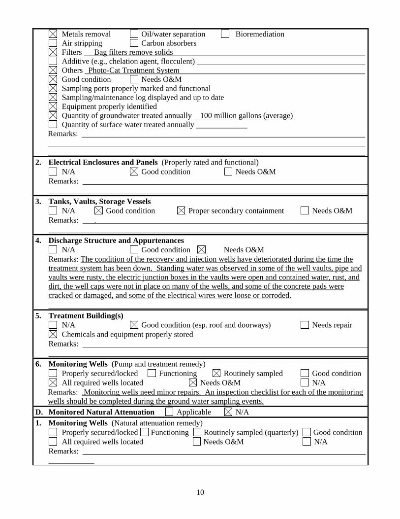
Metals removal Oil/water separation Bioremediation Air stripping Carbon absorbers
Filters Bag filters remove solids Additive (e.g., chelation agent, flocculent) Others Photo-Cat Treatment System
Good condition Needs O&M Sampling ports properly marked and functional Sampling/maintenance log displayed and up to date
Equipment properly identified Quantity of groundwater treated annually 100 million gallons (average) Quantity of surface water treated annually
Remarks:
2. Electrical Enclosures and Panels (Properly rated and functional) N/A Good condition Needs O&M
Remarks:
3. Tanks, Vaults, Storage Vessels N/A Good condition Proper secondary containment Needs O&M
Remarks: .
4. Discharge Structure and Appurtenances N/A Good condition Needs O&M
Remarks: The condition of the recovery and injection wells have deteriorated during the time the treatment system has been down. Standing water was observed in some of the well vaults, pipe and vaults were rusty, the electric junction boxes in the vaults were open and contained water, rust, and dirt, the well caps were not in place on many of the wells, and some of the concrete pads were cracked or damaged, and some of the electrical wires were loose or corroded.
5. Treatment Building(s) N/A Good condition (esp. roof and doorways) Needs repair
Chemicals and equipment properly stored Remarks:
6. Monitoring Wells (Pump and treatment remedy) Properly secured/locked Functioning Routinely sampled Good condition
All required wells located Needs O&M N/A Remarks: .Monitoring wells need minor repairs. An inspection checklist for each of the monitoring wells should be completed during the ground water sampling events.
D. Monitored Natural Attenuation Applicable N/A
1. Monitoring Wells (Natural attenuation remedy) Properly secured/locked Functioning Routinely sampled (quarterly) Good condition
All required wells located Needs O&M N/A Remarks:
10

X. OTHER REMEDIES
If there are remedies applied at the site that are not covered above, attach an inspection sheet describing the physical nature and condition of any facility associated with the remedy. An example would be soil vapor extraction.
XI. OVERALL OBSERVATIONS
A. Implementation of the Remedy
Describe issues and observations relating to whether the remedy is effective and functioning as designed. Begin with a brief statement of what the remedy is to accomplish (i.e., to contain contaminant plume, minimize infiltration and gas emission, etc.).
The remedial objectives were to (1) prevent exposure to contaminated ground water, above acceptable risk levels, (2) prevent or minimize further migration of the ground water contaminant plume, (3) prevent or minimize further migration of contaminants from source materials to ground water, and (4) return ground waters to their expected beneficial uses wherever practicable. The selected remedy included the following elements: a ground water extraction and treatment system, a treated ground water re-infiltration system, an infiltration gallery for flushing hexavalent chromium through vadose zone soils, and a long term ground water monitoring program. The ion exchange system was removed in December 2010. The delivery of the replacement water treatment system, a Photo-Cat, was delayed until March 2012. The Photo-Cat has been installed and is undergoing start-up activities. The protectiveness of the remedy cannot be determined at this time. A follow up evaluation, including another site inspection, site interviews, and review of newly acquired data, should be performed to determine if the remedy is functioning as intended by the ROD.
B. Adequacy of O&M
The condition of the recovery and injection wells have deteriorated during the time the treatment system has been down. Standing water was observed in some of the well vaults, pipe and vaults were rusty, the electric junction boxes in the vaults were open and contained water, rust, and dirt, the well caps were not in place on many of the wells, and some of the concrete pads were cracked or damaged, and some of the electrical wires were loose or corroded.
C. Early Indicators of Potential Remedy Failure
The increase in chromium concentrations in downgradient wells in all three release areas areas (M&C, LM, and NCC) indicate that the plume is migrating. This is due to the ground water treatment system being shut down from December 2010 until June 2013.
11

D. Opportunities for Optimization Describe possible opportunities for optimization in monitoring tasks or the operation of the remedy
In situ remediation amendments were tested in the Machine and Casting area in 2011. While the amendments were effective in reducing the chromium concentrations they resulted in the release of arsenic, iron, and manganese from the aquifer matrix. A buffered amendment was injected in May 2013. If the amendment is effective at reducing the release of arsenic, iron, and manganese it could be used to reduce the pump and treat system.
12

SPRAGUE ROAD GROUNDWATER PLUME SUPERFUND SITE SECOND FIVE-YEAR REVIEW REPORT
Attachment 4 Site Inspection Photographs

SPRAGUE ROAD GROUNDWATER PLUME SUPERFUND SITE SECOND FIVE-YEAR REVIEW REPORT
This page intentionally left blank.
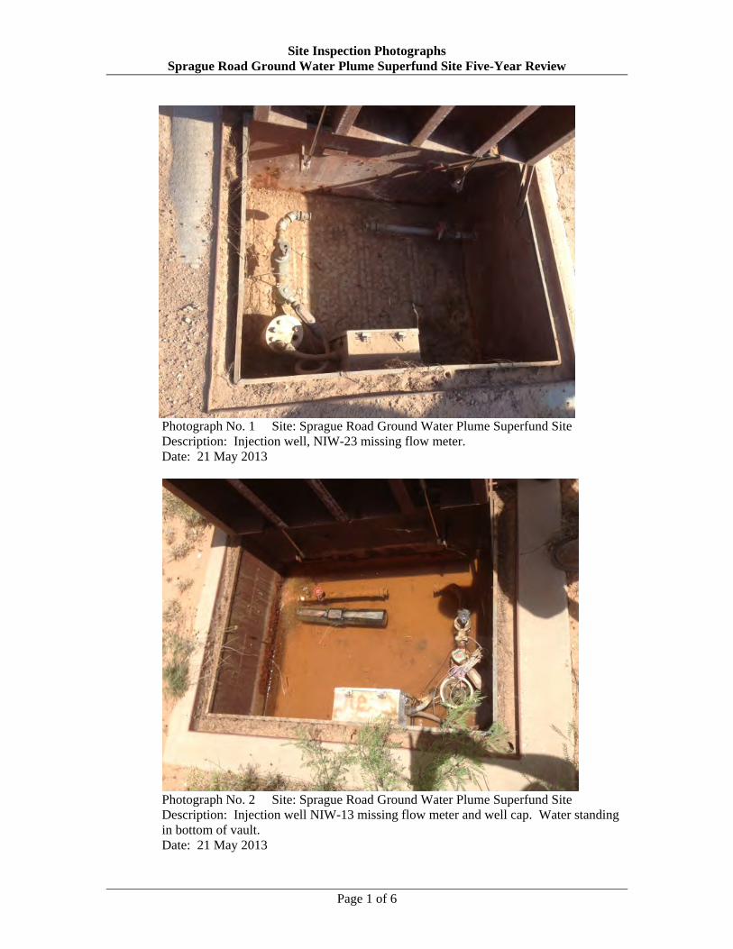
Site Inspection Photographs Sprague Road Ground Water Plume Superfund Site Five-Year Review
Photograph No. 1 Site: Sprague Road Ground Water Plume Superfund Site Description: Injection well, NIW-23 missing flow meter. Date: 21 May 2013
Photograph No. 2 Site: Sprague Road Ground Water Plume Superfund Site Description: Injection well NIW-13 missing flow meter and well cap. Water standing in bottom of vault. Date: 21 May 2013
Page 1 of 6

Site Inspection Photographs Sprague Road Ground Water Plume Superfund Site Five-Year Review
Photograph No. 3 Site: Sprague Road Ground Water Plume Superfund Site Description: Recovery well NRW-23 missing well cap, loose wires, and loose control box. Pump has been pulled for repair. Date: 21 May 2013
Photograph No. 4 Site: Sprague Road Ground Water Plume Superfund Site Description: Recovery well NRW-04. Seal for the pipe coming through the vault is missing. Date: 21 May 2013
Page 2 of 6

Site Inspection Photographs Sprague Road Ground Water Plume Superfund Site Five-Year Review
Photograph No. 5 Site: Sprague Road Ground Water Plume Superfund Site Description: Flooded vadose-zone flushing system control vault. Date: 21 May 2013
Photograph No. 6 Site: Sprague Road Ground Water Plume Superfund Site Description: Damaged fence at Leigh Metal facility. Date: 20 June 2013
Page 3 of 6
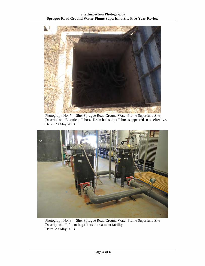
Site Inspection Photographs Sprague Road Ground Water Plume Superfund Site Five-Year Review
Photograph No. 7 Site: Sprague Road Ground Water Plume Superfund Site Description: Electric pull box. Drain holes in pull boxes appeared to be effective. Date: 20 May 2013
Photograph No. 8 Site: Sprague Road Ground Water Plume Superfund Site Description: Influent bag filters at treatment facility Date: 20 May 2013
Page 4 of 6

Site Inspection Photographs Sprague Road Ground Water Plume Superfund Site Five-Year Review
Photograph No. 9 Site: Sprague Road Ground Water Plume Superfund Site Description: Photo-Cat Treatment System Date: 20 May 2013
Photograph No. 10 Site: Sprague Road Ground Water Plume Superfund Site Description: Eyewash and emergency shower station next to Photo-Cat Treatment
System Date: 20 May 2013
Page 5 of 6

Site Inspection Photographs Sprague Road Ground Water Plume Superfund Site Five-Year Review
Photograph No. 11 Site: Sprague Road Ground Water Plume Superfund Site Description: Photo-Cat Treatment System Date: 20 May 2013
Page 6 of 6