Embed Size (px)
Citation preview
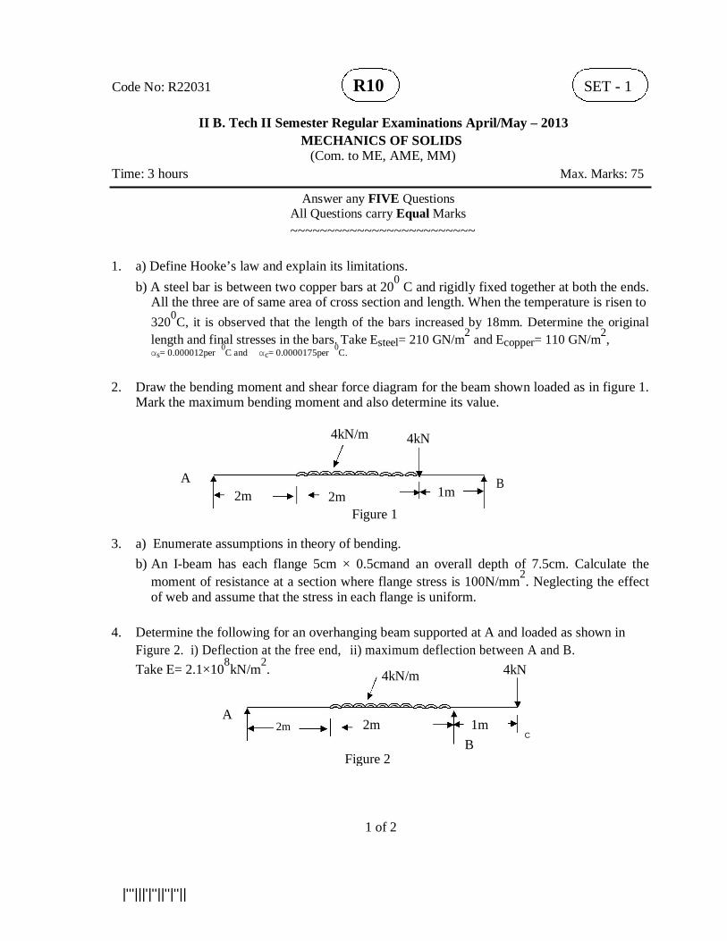
Code No: R22031 R10 SET - 1
II B. Tech II Semester Regular Examinations April/May – 2013 MECHANICS OF SOLIDS
(Com. to ME, AME, MM) Time: 3 hours Max. Marks: 75
Answer any FIVE Questions All Questions carry Equal Marks ~~~~~~~~~~~~~~~~~~~~~~~~~
1. a) Define Hooke’s law and explain its limitations.
b) A steel bar is between two copper bars at 200 C and rigidly fixed together at both the ends. All the three are of same area of cross section and length. When the temperature is risen to 3200C, it is observed that the length of the bars increased by 18mm. Determine the original length and final stresses in the bars. Take Esteel= 210 GN/m2 and Ecopper= 110 GN/m2, αs= 0.000012per 0C and αc= 0.0000175per 0C.
2. Draw the bending moment and shear force diagram for the beam shown loaded as in figure 1.
Mark the maximum bending moment and also determine its value.
4kN/m 4kN
A B 2m
1m
2m
Figure 1
3. a) Enumerate assumptions in theory of bending.
b) An I-beam has each flange 5cm × 0.5cmand an overall depth of 7.5cm. Calculate the moment of resistance at a section where flange stress is 100N/mm2. Neglecting the effect of web and assume that the stress in each flange is uniform.
4. Determine the following for an overhanging beam supported at A and loaded as shown in
Figure 2. i) Deflection at the free end, ii) maximum deflection between A and B.
Take E= 2.1×10⁸kN/m2. 4kN/m 4kN
A 2m 1m
2m
C
B
Figure 2
1 of 2 |'''|||'|''||''|''||
Code No: R22031 R10 SET - 1 5. a) Derive maximum shear stress variations in the L-section
b) A beam of triangular section having base width 20cm and height of 30cm is subjected to a shear force of 4kN. Find the value of maximum shear stress and sketch the shear stress distribution along the depth of the beam.
6. a) How will you find the reaction in a simply supported frame?
b) Warren girder freely supported at ends is loaded as shown in Figure 3 find the forces in all the members
60kN 40kN
8m Figure 3
7. A hollow circular column having the external and internal diameters of 300 mm and 250 mm
respectively carries a vertical load of 100kN at the outer edge of the column. Calculate the maximum and minimum intensities of stress across the section.
8. A cast iron pipe of 400mm internal diameter and 100mm thickness carries water under
pressure of 8N/mm2.Determine the maximum and minimum intensities of hoop stress across the section. Also sketch the radial pressure distribution and hoop stress distribution across the section.
2 of 2 |'''|||'|''||''|''||
Code No: R22031 R10 SET - 2
II B. Tech II Semester Regular Examinations April/May – 2013 MECHANICS OF SOLIDS
(Com. to ME, AME, MM) Time: 3 hours Max. Marks: 75
Answer any FIVE Questions All Questions carry Equal Marks ~~~~~~~~~~~~~~~~~~~~~~~~~
1. a) Derive the relation between E and K.
b) A mild steel flat, 320 mm long and 30mm × 50mm uniform section, is acted upon by the following loads uniformly over the respective cross section, 30kN in the direction of length (positive), 360kN in the direction of width(negative), 240kN in the direction of length (positive). Determine the change of length of the flat.
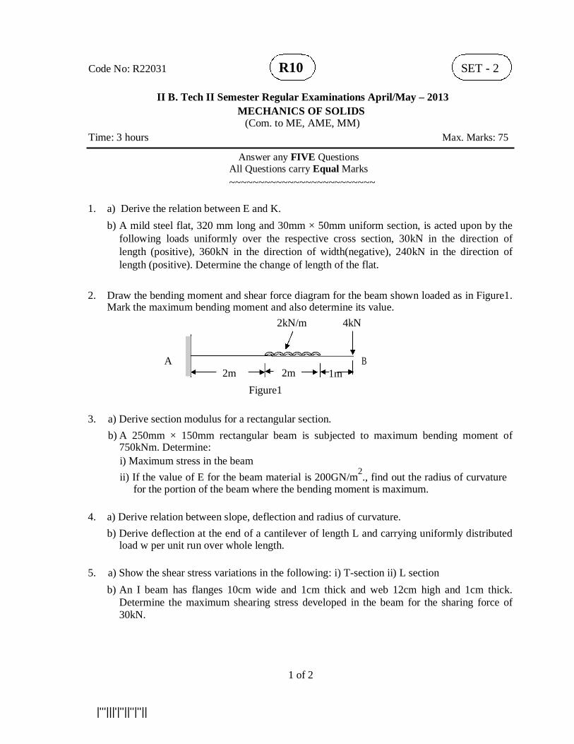
2. Draw the bending moment and shear force diagram for the beam shown loaded as in Figure1.
Mark the maximum bending moment and also determine its value. 2kN/m 4kN
A 2m
B
2m 1m
Figure1
3. a) Derive section modulus for a rectangular section.
b) A 250mm × 150mm rectangular beam is subjected to maximum bending moment of 750kNm. Determine: i) Maximum stress in the beam ii) If the value of E for the beam material is 200GN/m2., find out the radius of curvature
for the portion of the beam where the bending moment is maximum. 4. a) Derive relation between slope, deflection and radius of curvature.
b) Derive deflection at the end of a cantilever of length L and carrying uniformly distributed load w per unit run over whole length.
5. a) Show the shear stress variations in the following: i) T-section ii) L section
b) An I beam has flanges 10cm wide and 1cm thick and web 12cm high and 1cm thick. Determine the maximum shearing stress developed in the beam for the sharing force of 30kN.
1 of 2 |'''|||'|''||''|''||
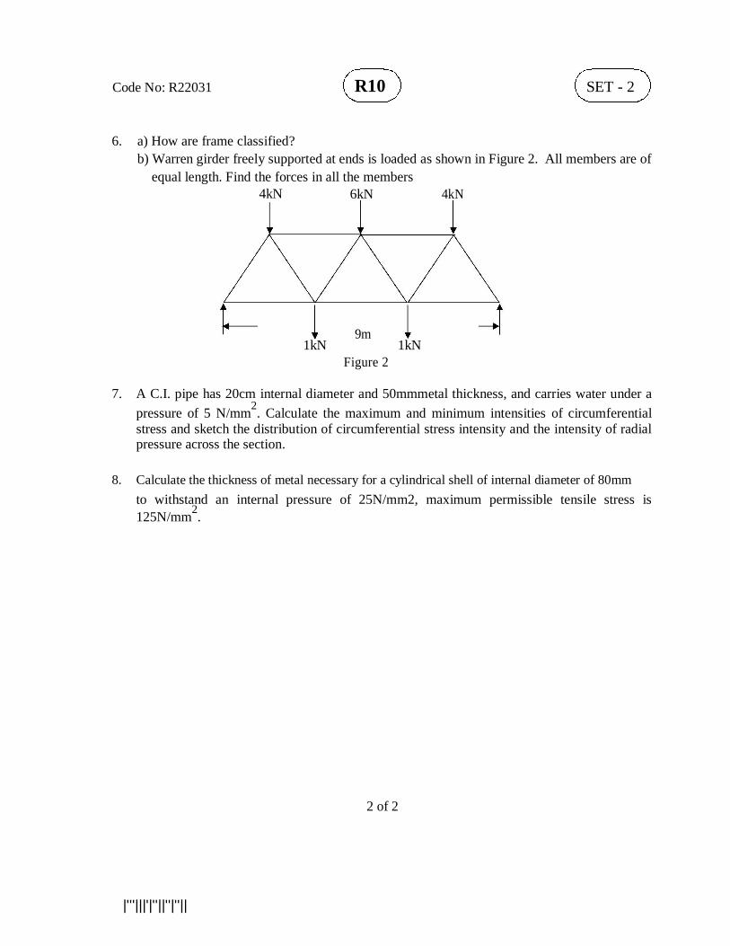
Code No: R22031 R10 SET - 2 6. a) How are frame classified?
b) Warren girder freely supported at ends is loaded as shown in Figure 2. All members are of equal length. Find the forces in all the members
4kN 6kN 4kN
9m
1kN 1kN
Figure 2
7. A C.I. pipe has 20cm internal diameter and 50mmmetal thickness, and carries water under a
pressure of 5 N/mm2. Calculate the maximum and minimum intensities of circumferential stress and sketch the distribution of circumferential stress intensity and the intensity of radial pressure across the section.
8. Calculate the thickness of metal necessary for a cylindrical shell of internal diameter of 80mm
to withstand an internal pressure of 25N/mm2, maximum permissible tensile stress is 125N/mm2.
2 of 2 |'''|||'|''||''|''||
Code No: R22031 R10 SET - 3
II B. Tech II Semester Regular Examinations April/May – 2013 MECHANICS OF SOLIDS
(Com. to ME, AME, MM) Time: 3 hours Max. Marks: 75
Answer any FIVE Questions All Questions carry Equal Marks ~~~~~~~~~~~~~~~~~~~~~~~~~
1. a) Define and explain the concept of factor of safety.
b) A copper sleeve, 21 mm internal diameter and 27mm external diameter surrounds a 20mm steel bolt, one end of the sleeve being in contact with the shoulder of the bolt. The sleeve is 60mm long. After putting a rigid washer on the other end of the sleeve, a nut is screwed on the bolt trough 100. If the pitch of the threads is 2.5mm, find the stresses induced in the copper sleeve and steel bolt. Take Esteel= 210 GN/m2 and Ecopper= 110 GN/m2,
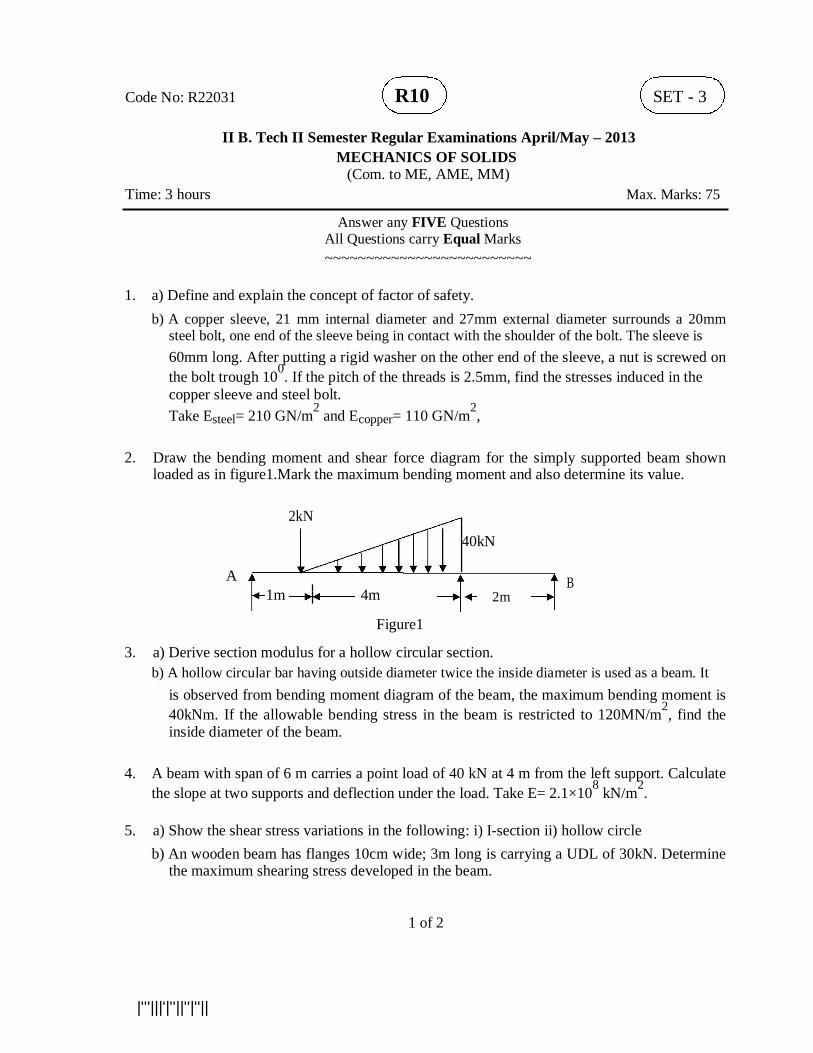
2. Draw the bending moment and shear force diagram for the simply supported beam shown
loaded as in figure1.Mark the maximum bending moment and also determine its value.
2kN
40kN
A
B
1m 4m
2m
Figure1 3. a) Derive section modulus for a hollow circular section.
b) A hollow circular bar having outside diameter twice the inside diameter is used as a beam. It is observed from bending moment diagram of the beam, the maximum bending moment is 40kNm. If the allowable bending stress in the beam is restricted to 120MN/m2, find the inside diameter of the beam.
4. A beam with span of 6 m carries a point load of 40 kN at 4 m from the left support. Calculate
the slope at two supports and deflection under the load. Take E= 2.1×10⁸ kN/m2. 5. a) Show the shear stress variations in the following: i) I-section ii) hollow circle
b) An wooden beam has flanges 10cm wide; 3m long is carrying a UDL of 30kN. Determine the maximum shearing stress developed in the beam.
1 of 2 |'''|||'|''||''|''||
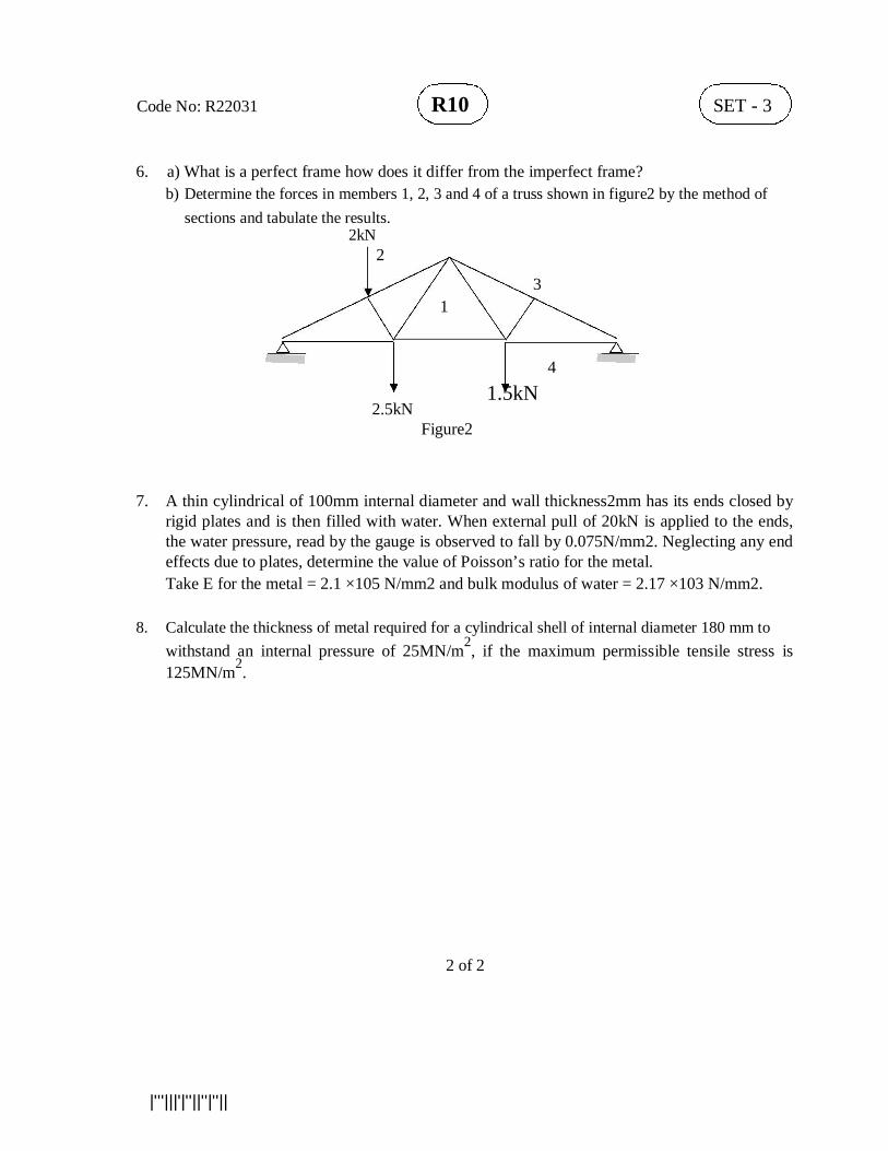
Code No: R22031 R10 SET - 3 6. a) What is a perfect frame how does it differ from the imperfect frame?
b) Determine the forces in members 1, 2, 3 and 4 of a truss shown in figure2 by the method of sections and tabulate the results.
2kN 2
3
1
4
2.5kN 1.5kN
Figure2
7. A thin cylindrical of 100mm internal diameter and wall thickness2mm has its ends closed by
rigid plates and is then filled with water. When external pull of 20kN is applied to the ends, the water pressure, read by the gauge is observed to fall by 0.075N/mm2. Neglecting any end effects due to plates, determine the value of Poisson’s ratio for the metal. Take E for the metal = 2.1 ×10⁵ N/mm2 and bulk modulus of water = 2.17 ×10³ N/mm2.
8. Calculate the thickness of metal required for a cylindrical shell of internal diameter 180 mm to
withstand an internal pressure of 25MN/m2, if the maximum permissible tensile stress is 125MN/m2.
2 of 2 |'''|||'|''||''|''||
Code No: R22031 R10 SET - 4
II B. Tech II Semester Regular Examinations April/May – 2013 MECHANICS OF SOLIDS
(Com. to ME, AME, MM) Time: 3 hours Max. Marks: 75
Answer any FIVE Questions All Questions carry Equal Marks ~~~~~~~~~~~~~~~~~~~~~~~~~
1. a) Explain different elastic moduli.
b) A uniform metal bar has a cross sectional area of 7cm2 and length of 18m. With the elastic limit of 160 MN/m2, what will be its proof resilience? Determine also the maximum value of an applied load which may be suddenly applied without exceeding elastic limit. Calculate the value of gradually applied load which will produce the same extension as that produced by the suddenly applied load above.
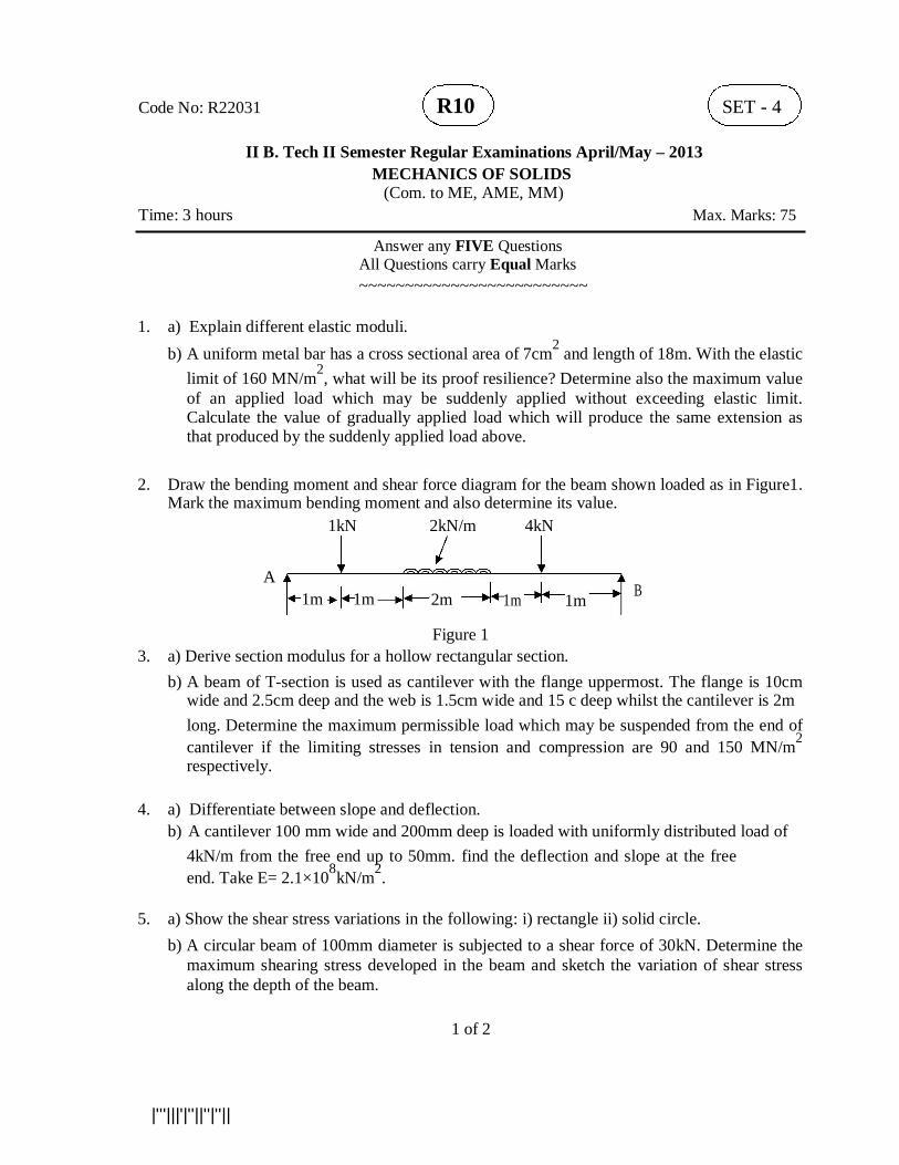
2. Draw the bending moment and shear force diagram for the beam shown loaded as in Figure1.
Mark the maximum bending moment and also determine its value. 1kN 2kN/m 4kN
A B 1m 1m 2m 1m 1m
Figure 1
3. a) Derive section modulus for a hollow rectangular section. b) A beam of T-section is used as cantilever with the flange uppermost. The flange is 10cm
wide and 2.5cm deep and the web is 1.5cm wide and 15 c deep whilst the cantilever is 2m long. Determine the maximum permissible load which may be suspended from the end of cantilever if the limiting stresses in tension and compression are 90 and 150 MN/m2 respectively.
4. a) Differentiate between slope and deflection.
b) A cantilever 100 mm wide and 200mm deep is loaded with uniformly distributed load of 4kN/m from the free end up to 50mm. find the deflection and slope at the free end. Take E= 2.1×10⁸kN/m2.
5. a) Show the shear stress variations in the following: i) rectangle ii) solid circle.
b) A circular beam of 100mm diameter is subjected to a shear force of 30kN. Determine the maximum shearing stress developed in the beam and sketch the variation of shear stress along the depth of the beam.
1 of 2
|'''|||'|''||''|''||
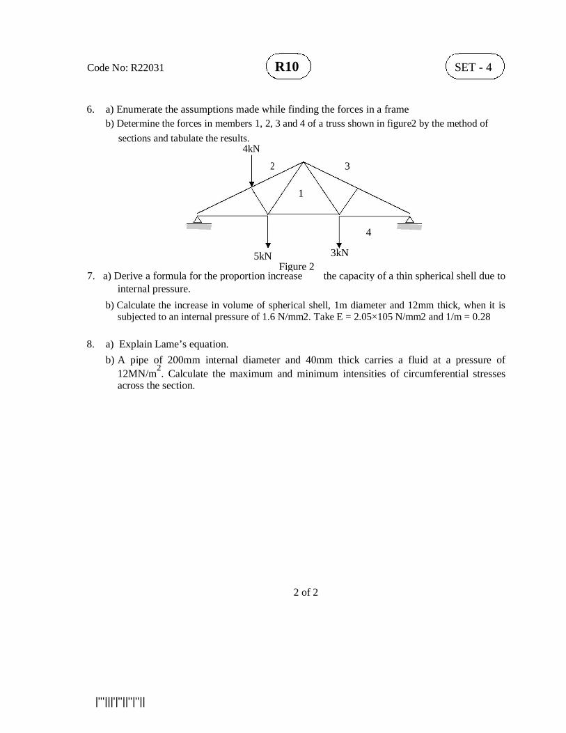
Code No: R22031 R10 SET - 4 6. a) Enumerate the assumptions made while finding the forces in a frame
b) Determine the forces in members 1, 2, 3 and 4 of a truss shown in figure2 by the method of sections and tabulate the results.
4kN 2 3
1
4
5kN 3kN
Figure 2
7. a) Derive a formula for the proportion increase the capacity of a thin spherical shell due to
internal pressure. b) Calculate the increase in volume of spherical shell, 1m diameter and 12mm thick, when it is
subjected to an internal pressure of 1.6 N/mm2. Take E = 2.05×10⁵ N/mm2 and 1/m = 0.28 8. a) Explain Lame’s equation.
b) A pipe of 200mm internal diameter and 40mm thick carries a fluid at a pressure of 12MN/m2. Calculate the maximum and minimum intensities of circumferential stresses across the section.
2 of 2 |'''|||'|''||''|''||
Code No: R22043 R10 SET - 1
II B. Tech II Semester Regular Examinations April/May – 2013 ELECTRONIC CIRCUIT ANALYSIS (Com. to ECE, EIE) Time: 3 hours Max. Marks: 75
Answer any FIVE Questions All Questions carry Equal Marks ~~~~~~~~~~~~~~~~~~~~~~~~
1. a) Draw the circuit diagram of Common Drain amplifier and derive an expression for its
Voltage gain. b) The h-parameters of the transistor used in CE amplifier are hfe = 50, hie =1.1K,
hre = 2.5×10⁻⁴, hoe = 24µ A/V. Find out current gain and voltage gains with and without source resistance , input and output impedances , given that RL= 10 K and RS= 1 K
2. a) Explain the nature of feedback in an emitter follower circuit. State the advantages of this
circuit and mention its use. Can this circuit be used as a voltage amplifier? b) The total harmonic distortion of an amplifier is reduced from 15% to 3% when 4% negative
feedback is used. Find (i) voltage gain without feedback (ii) voltage gain with feedback?
3. a) Describe the crystal oscillator. What is the advantage of a crystal oscillator over an LC
oscillator? b) A tuned collector oscillator connected across the primary has a capacitance of 100pF.The d.c resistance of the primary coil is 10 ohm and the transistor used has hie=1k ohm, hre=10-4, hfe=50 and hoe=10-4 A/V. Find the frequency of oscillation and the mutual inductance between the primary and secondary coils required to sustain the oscillations ?
4. a) Draw the circuit of two stages R-C coupled JFET amplifier and explain its working.
b) Draw the circuit diagram of single stage R-C coupled BJT amplifier. Discuss the effect of an emitter bypass capacitor on low-frequency response.
5. a) Derive the expression for the CE short circuit current gain Ai as a function of frequency using
Hybrid - π model. b) A single-stage CE amplifier is measured to have a voltage - gain bandwidth fH of 5 MHz
with RL = 500. Assume hfe = 100, gm=100 mA/V, rbb′ = 100, Cc = 1pF, and fT = 400 MHz. Find the value of the source resistance that will give the required bandwidth.
1 of 2


![Owner's Manual – MAGURA HS...Type name HS 11 HS 22 HS 33 Clamping Ø brake lever(E) [TD] mm 22+0.3/-0.1 Cantilever socket distance(F) 80±.2.0 Cantilever socket brake track area](https://img.pdfslide.us/doc/110x75/61176bf6c9c8cd257f121f33/owners-manual-a-magura-hs-type-name-hs-11-hs-22-hs-33-clamping-brake-levere.jpg)