Embed Size (px)
Citation preview
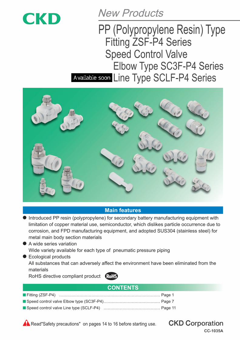
Main features Introduced PP resin (polypropylene) for secondary battery manufacturing equipment with limitation of copper material use, semiconductor, which dislikes particle occurrence due to corrosion, and FPD manufacturing equipment, and adopted SUS304 (stainless steel) for metal main body section materials
A wide series variationWide variety available for each type of pneumatic pressure piping
Ecological productsAll substances that can adversely affect the environment have been eliminated from the materialsRoHS directive compliant product
CONTENTS Fitting (ZSF-P4) ………………………………………………………………… Page 1 Speed control valve Elbow type (SC3F-P4) …………………………………… Page 7 Speed control valve Line type (SCLF-P4) …………………………………… Page 11
New ProductsPP (Polypropylene Resin) Type
Fitting ZSF-P4 SeriesSpeed Control Valve
Elbow Type SC3F-P4 SeriesLine Type SCLF-P4 Series
Read"Safety precautions" on pages 14 to 16 before starting use.CC-1035A
1
PP (polypropylene resin) type Fitting
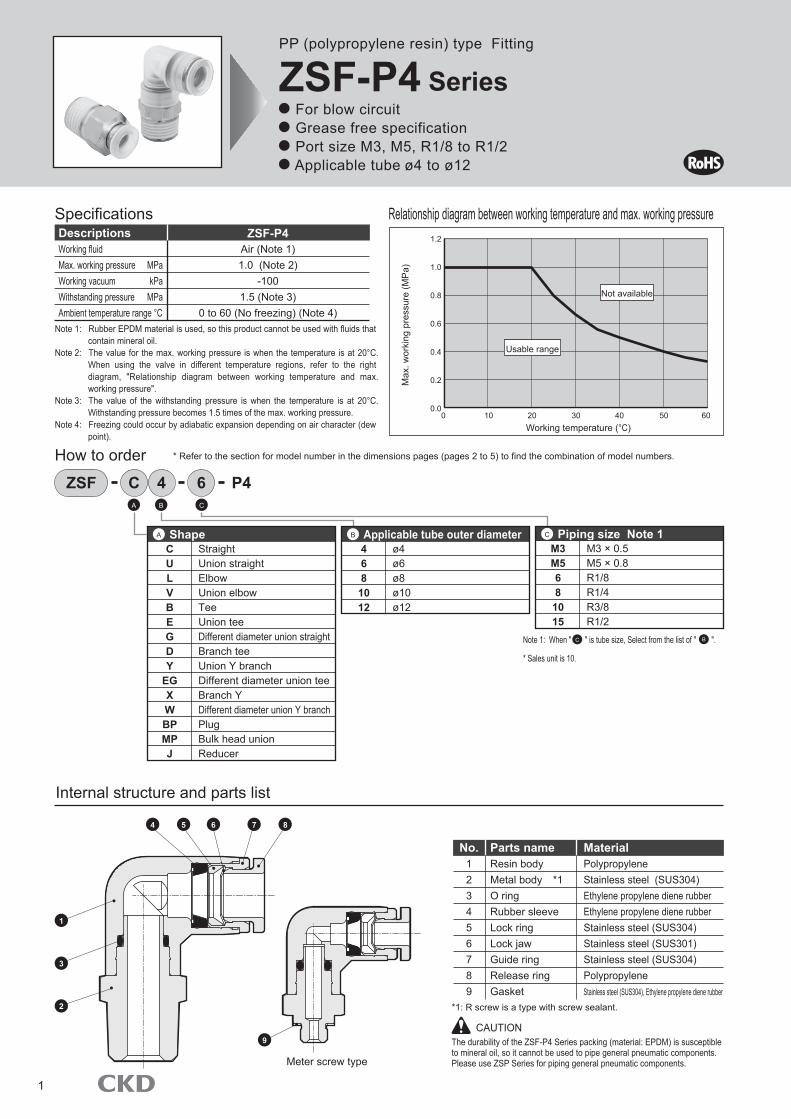
ZSF-P4 Series For blow circuit Grease free specification Port size M3, M5, R1/8 to R1/2 Applicable tube ø4 to ø12
Specifications Relationship diagram between working temperature and max. working pressure
Working fluidMax. working pressure MPaWorking vacuum kPaWithstanding pressure MPaAmbient temperature range °C
Air (Note 1)1.0 (Note 2)
-1001.5 (Note 3)
0 to 60 (No freezing) (Note 4)
Descriptions ZSF-P4
* Refer to the section for model number in the dimensions pages (pages 2 to 5) to find the combination of model numbers.
Note 1: When " " is tube size, Select from the list of " ".
* Sales unit is 10.
Internal structure and parts list
Note 1: Rubber EPDM material is used, so this product cannot be used with fluids that contain mineral oil.
Note 2: The value for the max. working pressure is when the temperature is at 20°C. When using the valve in different temperature regions, refer to the right diagram, "Relationship diagram between working temperature and max. working pressure".
Note 3: The value of the withstanding pressure is when the temperature is at 20°C. Withstanding pressure becomes 1.5 times of the max. working pressure.
Note 4: Freezing could occur by adiabatic expansion depending on air character (dew point).
CULVBEGDY
EGXWBPMPJ
StraightUnion straightElbowUnion elbowTeeUnion teeDifferent diameter union straightBranch teeUnion Y branchDifferent diameter union teeBranch YDifferent diameter union Y branchPlugBulk head unionReducer
ShapeA
How to order
A B
B
C
C
ZSF C 4 6 P4
4681012
ø4ø6ø8ø10ø12
Applicable tube outer diameterB
M3M5681015
M3 × 0.5M5 × 0.8R1/8R1/4R3/8R1/2
Piping size Note 1C
No. Parts name Material123456789
Resin bodyMetal body *1O ringRubber sleeveLock ringLock jawGuide ringRelease ringGasket
PolypropyleneStainless steel (SUS304)Ethylene propylene diene rubberEthylene propylene diene rubberStainless steel (SUS304)Stainless steel (SUS301)Stainless steel (SUS304)PolypropyleneStainless steel (SUS304), Ethylene propylene diene rubber
*1: R screw is a type with screw sealant.
The durability of the ZSF-P4 Series packing (material: EPDM) is susceptible to mineral oil, so it cannot be used to pipe general pneumatic components. Please use ZSP Series for piping general pneumatic components.
CAUTION9
87654
3
1
2
Meter screw type
1.2
1.0
0.8
0.6
0.4
0.2
0.00 10 20 30
Working temperature (°C)40 50 60
Usable range
Not available
Max
. wor
king
pre
ssur
e (M
Pa)
2
DimensionsZSF Series
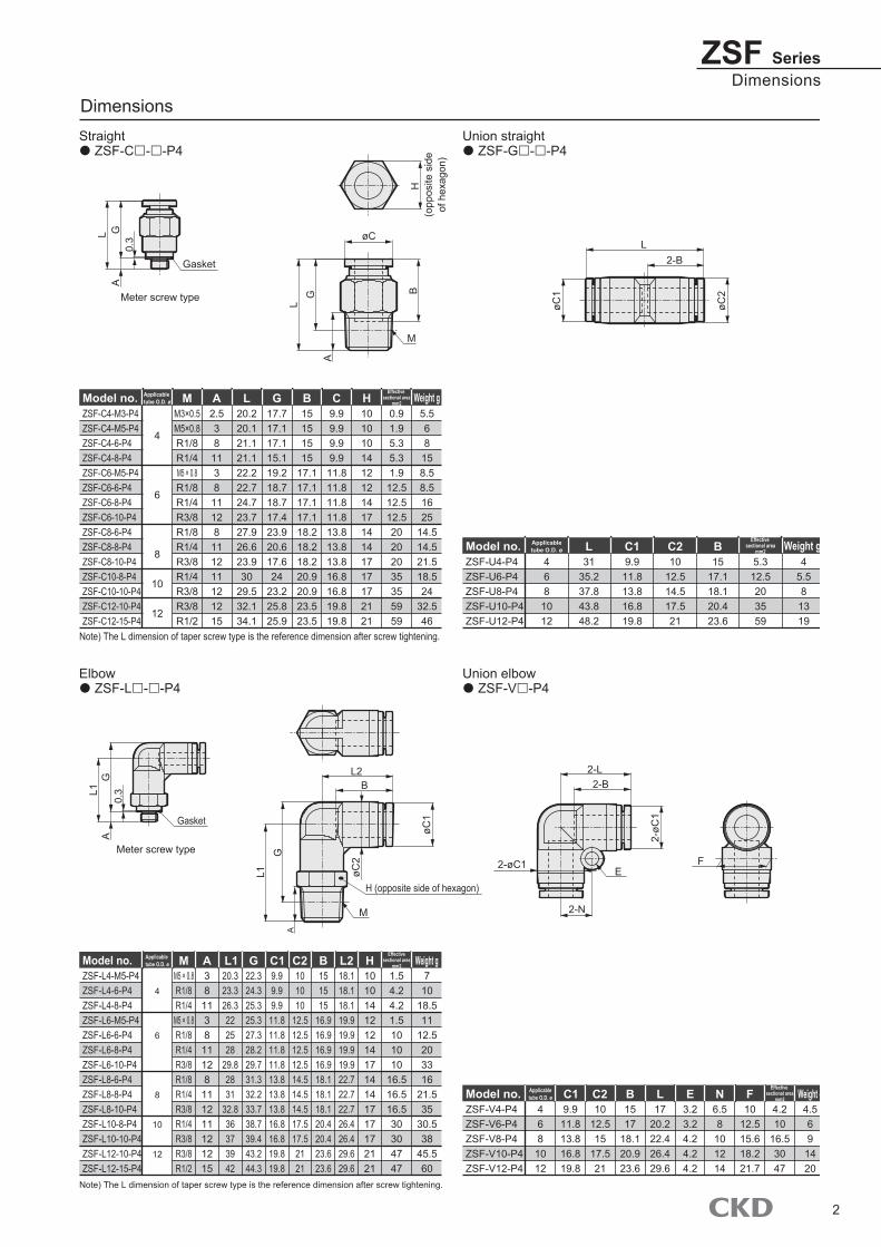
Straight ZSF-C - -P4
Union straight ZSF-G - -P4
Elbow ZSF-L - -P4
Union elbow ZSF-V -P4
Dimensions
ZSF-C4-M3-P4ZSF-C4-M5-P4ZSF-C4-6-P4ZSF-C4-8-P4ZSF-C6-M5-P4ZSF-C6-6-P4ZSF-C6-8-P4ZSF-C6-10-P4ZSF-C8-6-P4ZSF-C8-8-P4ZSF-C8-10-P4ZSF-C10-8-P4ZSF-C10-10-P4ZSF-C12-10-P4ZSF-C12-15-P4
Applicable tube O.D. øModel no.
4
6
8
10
12
MM3×0.5M5×0.8R1/8R1/4M5 × 0.8R1/8R1/4R3/8R1/8R1/4R3/8R1/4R3/8R3/8R1/2
A2.538113811128111211121215
L20.220.121.121.122.222.724.723.727.926.623.930
29.532.134.1
G17.717.117.115.119.218.718.717.423.920.617.624
23.225.825.9
C9.99.99.99.911.811.811.811.813.813.813.816.816.819.819.8
B15151515
17.117.117.117.118.218.218.220.920.923.523.5
H101010141212141714141717172121
Effective sectional area
mm2
0.91.95.35.31.9
12.512.512.520202035355959
Weight g5.568
158.58.51625
14.514.521.518.524
32.546
ZSF-U4-P4ZSF-U6-P4ZSF-U8-P4ZSF-U10-P4ZSF-U12-P4
Applicabletube O.D. øModel no.
468
1012
L31
35.237.843.848.2
C210
12.514.517.521
C19.9
11.813.816.819.8
B15
17.118.120.423.6
Effective sectional area
mm2
5.312.5203559
Weight g4
5.581319
ZSF-L4-M5-P4ZSF-L4-6-P4ZSF-L4-8-P4ZSF-L6-M5-P4ZSF-L6-6-P4ZSF-L6-8-P4ZSF-L6-10-P4ZSF-L8-6-P4ZSF-L8-8-P4ZSF-L8-10-P4ZSF-L10-8-P4ZSF-L10-10-P4ZSF-L12-10-P4ZSF-L12-15-P4
Applicable tube O.D. øModel no.
4
6
8
10
12
MM5 × 0.8R1/8R1/4
M5 × 0.8R1/8R1/4R3/8R1/8R1/4R3/8R1/4R3/8R3/8R1/2
A38113811128111211121215
L120.323.326.3222528
29.82831
32.836373942
G22.324.325.325.327.328.229.731.332.233.738.739.443.244.3
C19.99.99.911.811.811.811.813.813.813.816.816.819.819.8
C2101010
12.512.512.512.514.514.514.517.517.52121
B151515
16.916.916.916.918.118.118.120.420.423.623.6
L218.118.118.119.919.919.919.922.722.722.726.426.429.629.6
H1010141212141714141717172121
Effectivesectional area
mm2
1.54.24.21.5101010
16.516.516.530304747
Weight g7
1018.511
12.5203316
21.535
30.538
45.560
Note) The L dimension of taper screw type is the reference dimension after screw tightening.
Note) The L dimension of taper screw type is the reference dimension after screw tightening.
ZSF-V4-P4ZSF-V6-P4ZSF-V8-P4ZSF-V10-P4ZSF-V12-P4
Applicabletube O.D. øModel no.
468
1012
C19.9
11.813.816.819.8
C210
12.515
17.521
B1517
18.120.923.6
L17
20.222.426.429.6
N6.58
101214
E3.23.24.24.24.2
F10
12.515.618.221.7
Effective sectional area
mm2
4.210
16.53047
Weight g4.5691420
0.3
M
B
AG
L
Gasket
GLA
H (o
ppos
ite s
ide
of h
exag
on)
0.3
H (opposite side of hexagon)
Meter screw type
Meter screw type
Gasket
L1A
G
M
L2
A
L1G
B
L2-B
2-N
2-L2-B
F
øC
øC1
øC2
2-øC
1
øC1
øC2 2-øC1
E
3
ZSF Series
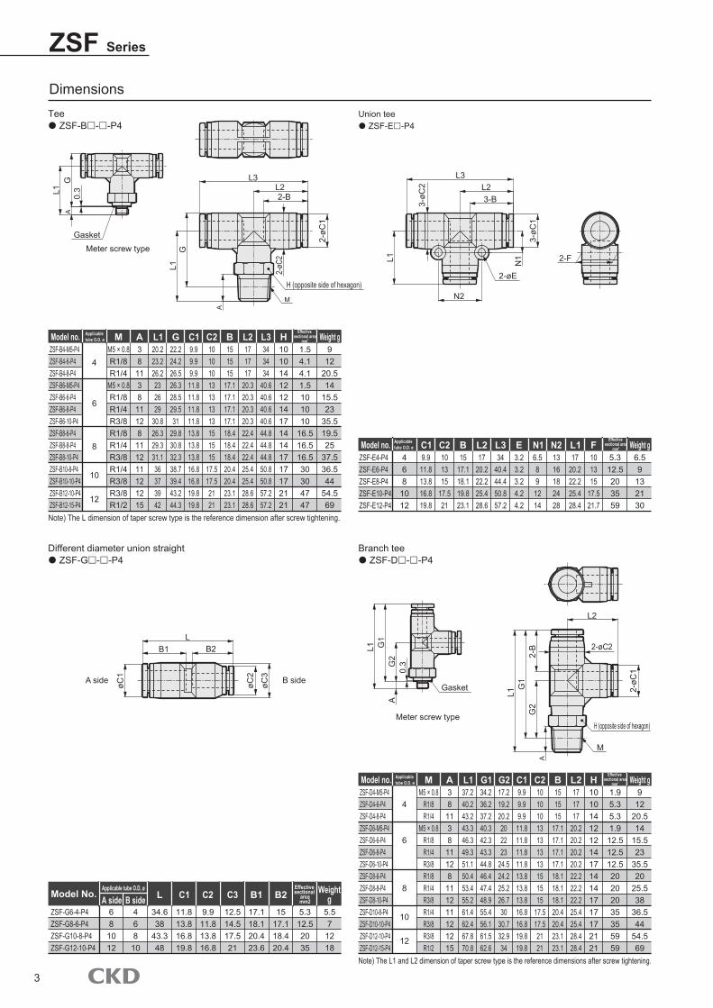
Tee ZSF-B - -P4
Union tee ZSF-E -P4
Different diameter union straight ZSF-G - -P4
Branch tee ZSF-D - -P4
Dimensions
ZSF-B4-M5-P4ZSF-B4-6-P4ZSF-B4-8-P4ZSF-B6-M5-P4ZSF-B6-6-P4ZSF-B6-8-P4ZSF-B6-10-P4ZSF-B8-6-P4ZSF-B8-8-P4ZSF-B8-10-P4ZSF-B10-8-P4ZSF-B10-10-P4ZSF-B12-10-P4ZSF-B12-15-P4
Model no.
4
6
8
10
12
MM5 × 0.8R1/8R1/4
M5 × 0.8R1/8R1/4R3/8R1/8R1/4R3/8R1/4R3/8R3/8R1/2
A38
1138
11128
111211121215
L120.223.226.2232629
30.826.329.331.136373942
G22.224.226.526.328.529.531
29.830.832.338.739.443.244.3
L2171717
20.320.320.320.322.422.422.425.425.428.628.6
L3343434
40.640.640.640.644.844.844.850.850.857.257.2
C19.99.99.911.811.811.811.813.813.813.816.816.819.819.8
C210101013131313151515
17.517.52121
B151515
17.117.117.117.118.418.418.420.420.423.123.1
H1010141212141714141717172121
1.54.14.11.5101010
16.516.516.530304747
Weight g9
1220.514
15.523
35.519.525
37.536.544
54.569
ZSF-E4-P4ZSF-E6-P4ZSF-E8-P4ZSF-E10-P4ZSF-E12-P4
Model no.468
1012
L117
20.222.225.428.4
L217
20.222.225.428.6
L334
40.444.450.857.2
E3.23.23.24.24.2
N16.5891214
N21316182428
C19.911.813.816.819.8
C2101315
17.521
B15
17.118.119.823.1
F101315
17.521.7
5.312.5203559
Weight g6.59132130
Note) The L dimension of taper screw type is the reference dimension after screw tightening.
Note) The L1 and L2 dimension of taper screw type is the reference dimensions after screw tightening.
ZSF-G6-4-P4ZSF-G8-6-P4ZSF-G10-8-P4ZSF-G12-10-P4
A sideApplicable tube O.D, ø
Model No.
681012
B side46810
L
34.638
43.348
C1
11.813.816.819.8
C2
9.911.813.816.8
B1
17.118.120.423.6
C3
12.514.517.521
B2
1517.118.420.4
Effective sectional
areamm2
5.312.52035
Weightg
5.57
1218
ZSF-D4-M5-P4ZSF-D4-6-P4ZSF-D4-8-P4ZSF-D6-M5-P4ZSF-D6-6-P4ZSF-D6-8-P4ZSF-D6-10-P4ZSF-D8-6-P4ZSF-D8-8-P4ZSF-D8-10-P4ZSF-D10-8-P4ZSF-D10-10-P4ZSF-D12-10-P4ZSF-D12-15-P4
Applicable tube O.D. ø
Applicable tube O.D. ø
Applicable tube O.D. ø
Model no.
4
6
8
10
12
MM5 × 0.8
R1/8R1/4
M5 × 0.8R1/8R1/4R3/8R1/8R1/4R3/8R1/4R3/8R3/8R1/2
A38113811128111211121215
L137.240.243.243.346.349.351.150.453.455.261.462.467.870.8
G134.236.237.240.342.343.344.846.447.448.955.456.161.562.6
B151515
17.117.117.117.118.118.118.120.420.423.123.1
L2171717
20.220.220.220.222.222.222.225.425.428.428.4
G217.219.220.2202223
24.524.225.226.730
30.732.934
C19.99.99.9
11.811.811.811.813.813.813.816.816.819.819.8
C210101013131313151515
17.517.52121
H1010141212141714141717172121
Effective sectional area
mm2
Effective sectional area
mm2
Effective sectional area
mm2
1.95.35.31.9
12.512.512.520202035355959
Weight g912
20.514
15.523
35.520
25.538
36.544
54.569
0.3
Gasket
A
L1G
H (opposite side of hexagon)
M
2-BL2
L3
A
GL1
Meter screw type
Meter screw type
2-FL1
N2
N1
3-BL2
L3
0.3
H (opposite side of hexagon)
M
Gasket
L1
AG
2G
1
L2
2-B
AG
2
L1G
1
LB2
øC2
2-øC
1
øC3
øC1
B1 2-øC2
3-øC
1
3-øC
2
2-øC
2
2-øC
1
2-øE
A side B side
4
DimensionsZSF Series
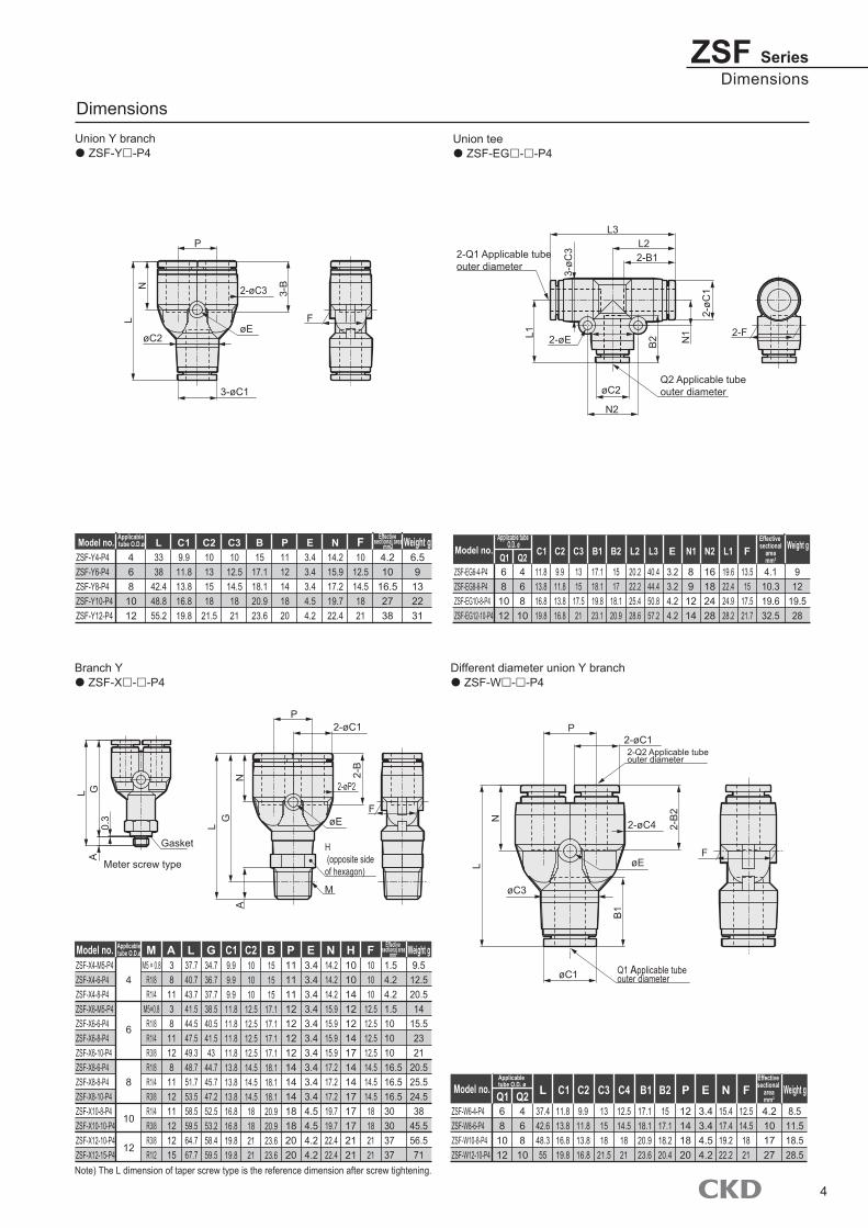
Union Y branchò ZSF-Y£-P4
Union teeò ZSF-EG£-£-P4
Branch Yò ZSF-X£-£-P4
Dimensions
Different diameter union Y branchò ZSF-W£-£-P4
ZSF-Y4-P4ZSF-Y6-P4ZSF-Y8-P4ZSF-Y10-P4ZSF-Y12-P4
Model no.4681012
L3338
42.448.855.2
C19.9
11.813.816.819.8
C2 C310131518
21.5
1012.514.51821
B15
17.118.120.923.6
P1112141820
E3.43.43.44.54.2
N14.215.917.219.722.4
F10
12.514.51821
4.210
16.52738
Weight g6.59
132231
ZSF-EG6-4-P4ZSF-EG8-6-P4ZSF-EG10-8-P4ZSF-EG12-10-P4
Model no.
68
1012
11.813.816.819.8
4.110.319.632.5
912
19.528
Q1468
10
Q2 C1
9.911.813.816.8
C2
1315
17.521
C3
17.118.119.823.1
B1
1517
18.120.9
B2
20.222.225.428.6
L2
40.444.450.857.2
L3
3.23.24.24.2
E
89
1214
N1
16182428
N2
19.622.424.928.2
L1
13.515
17.521.7
FEffective sectional
areamm2
Weight g
ZSF-X4-M5-P4ZSF-X4-6-P4ZSF-X4-8-P4ZSF-X6-M5-P4ZSF-X6-6-P4ZSF-X6-8-P4ZSF-X6-10-P4ZSF-X8-6-P4ZSF-X8-8-P4ZSF-X8-10-P4ZSF-X10-8-P4ZSF-X10-10-P4ZSF-X12-10-P4ZSF-X12-15-P4
Applicable tube O.D.ø
Applicable tube O.D.ø
Model no.
4
6
8
10
12
NG EPC1 C2 B FH Effective sectional area
mm2
Effective sectional area
mm2
1.54.24.21.510101016.516.516.530303737
Weight g9.512.520.514
15.52321
20.525.524.538
45.556.571
Note) The L dimension of taper screw type is the reference dimension after screw tightening.
LA38
1138
11128
111211121215
37.740.743.741.544.547.549.348.751.753.558.559.564.767.7
34.736.737.738.540.541.543
44.745.747.252.553.258.459.5
9.99.99.911.811.811.811.813.813.813.816.816.819.819.8
101010
12.512.512.512.514.514.514.518182121
151515
17.117.117.117.118.118.118.120.920.923.623.6
1111111212121214141418182020
3.43.43.43.43.43.43.43.43.43.44.54.54.24.2
14.214.214.215.915.915.915.917.217.217.219.719.722.422.4
1010141212141714141717172121
101010
12.512.512.512.514.514.514.518182121
MM5 × 0.8
R1/8R1/4
M5×0.8R1/8R1/4R3/8R1/8R1/4R3/8R1/4R3/8R3/8R1/2
Applicable tube O.D. ø
ZSF-W6-4-P4ZSF-W8-6-P4ZSF-W10-8-P4ZSF-W12-10-P4
Model no.
68
1012
468
10
NP EC1 C2 C3 C4 B1 B2 FEffective sectional
areamm2
4.2101727
Weight g
8.511.518.528.5
37.442.648.355
11.813.816.819.8
9.911.813.816.8
131518
21.5
12.514.51821
17.118.120.923.6
1517.118.220.4
12141820
3.43.44.54.2
15.417.419.222.2
12.514.51821
LQ1
Applicable tube O.D. ø
Q2
øE
2-øC3
øC2
3-øC1
F
NL
P
3-B
2-F
B2L1
3-øC
3
2-øC
1
N2
N1
2-B1
øC2
2-øE
L2L3
F
0.3
Gasket
AL G
M
H (opposite side of hexagon)
A
LG
N 2-B
P2-øC1
øE
2-øP2
Meter screw type
Q2 Applicable tubeouter diameter
2-Q1 Applicable tube outer diameter
2-øC1
øE
øC3
øC1
2-øC4N
L
B1
2-B
2
P
F
2-Q2 Applicable tube outer diameter
Q1 Applicable tube outer diameter
5
ZSF Series
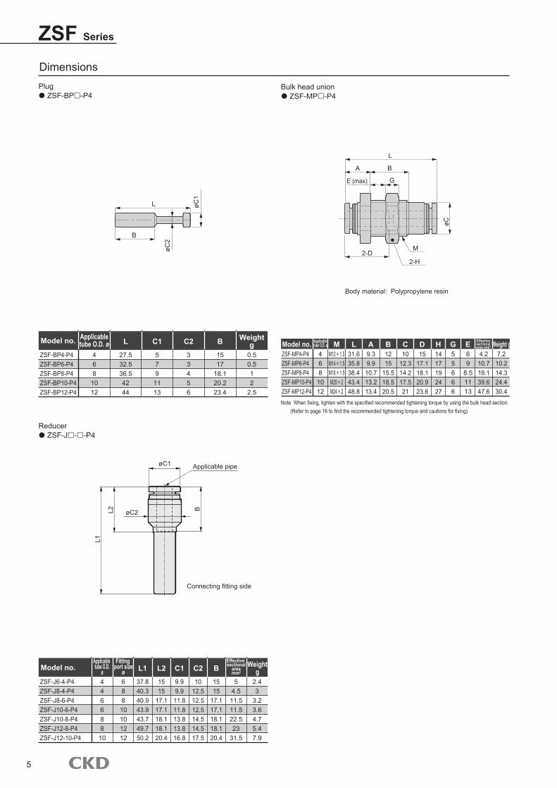
Plug ZSF-BP -P4
Bulk head union ZSF-MP -P4
Dimensions
Reducer ZSF-J - -P4
Applicable pipe
Connecting fitting side
ZSF-MP4-P4ZSF-MP6-P4ZSF-MP8-P4ZSF-MP10-P4ZSF-MP12-P4
Applicabletube O.D. øModel no.
468
1012
B C D31.635.838.443.448.8
9.39.910.713.213.4
1215
15.518.520.5
1012.314.217.521
1517.118.120.923.6
1417192427
69
8.51113
LM12 × 1.5M14 × 1.5M16 × 1.5M20 × 2M24 × 2
M A EH Effective sectional area mm2
4.210.719.139.647.6
Weight g7.210.214.324.430.4
ZSF-J6-4-P4ZSF-J8-4-P4ZSF-J8-6-P4ZSF-J10-6-P4ZSF-J10-8-P4ZSF-J12-8-P4ZSF-J12-10-P4
Applicable tube O.D.
øFitting
port sizeøModel no.
44668810
68810101212
L1
37.840.340.943.943.749.750.2
L2
1515
17.117.118.118.120.4
B
1515
17.117.118.118.120.4
C1
9.99.911.811.813.813.816.8
C2
1012.512.512.514.514.517.5
2.43
3.23.64.75.47.9
54.511.511.522.523
31.5
Effective sectional
areamm2
Weightg
ZSF-BP4-P4ZSF-BP6-P4ZSF-BP8-P4ZSF-BP10-P4ZSF-BP12-P4
Applicabletube O.D. øModel no.
4681012
L
27.532.536.54244
B
1517
18.120.223.4
C1
5791113
C2
33456
0.50.512
2.5
Weightg
55666
G
Body material: Polypropylene resin
øC2
øC1
B
L
øC
2-DM
L
B
G
A
2-H
E (max)
L1
L2 BøC2
øC1
Note When fixing, tighten with the specified recommended tightening torque by using the bulk head section. (Refer to page 16 to find the recommended tightening torque and cautions for fixing)

6

7
PP (polypropylene resin) type Speed control valve Elbow
SC3F-P4 Series For air operated components Port size M3, M5, R1/8 to R1/2
Specifications
Applicable tube outer diameter mmWorking fluidMax. working pressure MPaMin. working pressure MPaWithstanding pressure MPaAmbient temperature range °CPort size RcProduct weight gNumber of needle turn
Air1.0 (Note 1)
0.11.5 (Note 2)
0 to 60 (No freezing) (Note 3)
ø4ø4
M37.8
ø6 ø4 ø6 ø8 ø6 ø8 ø10 ø6 ø8 ø10 ø12 ø10 ø12
M5
7 and over
R1/8 R1/441
12 and over
R3/87 8 18 19 22 38 44 67 69 71
13 and over74
R1/2109
Model no.Descriptions
SC3F-P4SC3F-M5SC3F-M3 SC3F-6 SC3F-8 SC3F-10 SC3F-15
0.9 (Note 1)
1.35 (Note 2)
106
Note 1: The value for the max. working pressure is when the temperature is at 20°C. When using the valve in different temperature regions, refer to page 9, "Relationship diagram between working temperature and the max. working pressure".
Note 2: The value of the withstanding pressure is when the temperature is at 20°C. Withstanding pressure becomes 1.5 times of the max. working pressure. Note 3: Freezing could occur by adiabatic expansion depending on air character (dew point).
How to order
Model no.
A Port size
B Applicable tube outer diameter
C Option
ø4ø6ø8ø10ø12
4681012
Port sizeApplicable tube outer diameterB
SC3F 8 8 I P4M3M5681015
M3 × 0.5M5 × 0.8R1/8R1/4R3/8R1/2
Port sizeASymbol Description
BlankI
Meter-out controlMeter-in control (Custom order)
Control methodC
M5ò
ò
M3ò
6ò
ò
ò
8
ò
ò
ò
10
ò
ò
ò
ò
15
ò
ò
are not available.
Flow and effective sectional area
Applicable tube outer diameter mmFree flow
Controlledflow
ø4ø4400.665
0.95
ø6 ø4 ø6
1502.2
ø8 ø63905.8
ø8
2704
ø10 ø66008.85508
ø8 ø10 ø1284012.4
ø10
145021.5
ø12
160023.5
550.8701.0
2003
4005.9
92013.5
80012
2303.4
85012.5
138020.5
Model no.Descriptions
SC3F-P4SC3F-M5SC3F-M3 SC3F-6 SC3F-8 SC3F-10 SC3F-15
Note 1: The flow is the atmospheric pressure conversion value at pressure 0.5 MPa. Note 2: For the effective sectional area, corresponding value from the flow is written.
Flow /min (ANR)Effective sectional area mm2
Flow /min (ANR)Effective sectional area mm2
Meter-out control¢ Control method
JIS
sym
bol
Male thread side
Meter-in control
Male thread side
JIS symbol

8
Flow characteristicsSC3F Series
Pressure (MPa)
Pressure (MPa)
Pressure (MPa)
Pressure (MPa)
Flow
/min(
ANR)
Flow
/min(
ANR)
Flow
/min(
ANR)
Flow
/min(
ANR)
Flow
/min(
ANR)
at 0
.5 M
Pa
Flow
/min(
ANR)
at 0
.5 M
PaFl
ow/m
in(AN
R) a
t 0.5
MPa
Flow
/min(
ANR)
at 0
.5 M
Pa
Effe
ctiv
e se
ctio
nal a
rea
(mm
2 )
Effe
ctiv
e se
ctio
nal a
rea
(mm
2 )
Effe
ctiv
e se
ctio
nal a
rea
(mm
2 )
Effe
ctiv
e se
ctio
nal a
rea
(mm
2 )
Effe
ctiv
e se
ctio
nal a
rea
(mm
2 )
Effe
ctiv
e se
ctio
nal a
rea
(mm
2 )
Effe
ctiv
e se
ctio
nal a
rea
(mm
2 )
Effe
ctiv
e se
ctio
nal a
rea
(mm
2 )
0
10
20
30
40
50
60
70
80
0 2 4 6 71 3 5
0.2
0.4
0.6
0 0
50
100
150
200
250
300
0.8
1.0
1.2
3
1
2
0
4
0
100
200
300
400
500
600
700
800
900
1000
0 2 4 6 8 10 12
3
6
0 0
200
400
600
800
1000
1200
1400
1600
1800
9
12
15
20
10
15
0
25
5
Number of needle turn (times) Number of needle turn (times)
Number of needle turn (times)Number of needle turn (times)0 2 4 6 8 10 12
0 4 8 122 6 10
0
500
1000
1500
2000
2500
3000
0 0.1 0.2 0.3 0.4 0.5 0.6 0.7 0.8 0.9
30
20
0
10
0
200
400
600
800
1000
1200
1400
1600
0 0.1 0.2 0.3 0.4 0.5 0.6 0.7 0.8 0.9 1
SC3F-10-8/10
SC3F-8-8/10
SC3F-10-10/12SC3F-15-10/12
SC3F-10-6
SC3F-M3-4, SC3F-M5-*
[Free flow]
SC3F-6-*, SC3F-8-*
Flow characteristics
SC3F-10-* SC3F-15-*
SC3F-6-4/10
SC3F-10-10/12 SC3F-15-12
SC3F-15-10SC3F-10-8
SC3F-10-6
SC3F-M3-4, SC3F-M5-*
[Controlled flow]
SC3F-6-*, SC3F-8-*
SC3F-10-* SC3F-15-*
SC3F-8-6
SC3F-6-8
SC3F-6-4/6
SC3F-M5-*
SC3F-M3-4
SC3F-M3-4
SC3F-M5-*
SC3F-8-6
SC3F-6-*
0102030405060708090
100110120
0 0.1 0.2 0.3 0.4 0.5 0.6 0.7 0.8 0.9 1
0.2
0.4
0.6
0
1.0
0.8
1.2
1.4
1.6
1.8
0
100
200
300
400
500
600
700
800
900
1000
0 0.1 0.2 0.3 0.4 0.5 0.6 0.7 0.8 0.9 1
9
3
0
6
12
15

9
SC3F Series
Meter screw type Meter-out control
Meter-in control
Internal structure and parts list
7
8
91
2
3
4
5
6
78
6
15
10 11 12
13 14
1.2
1.0
0.8
0.6
0.4
0.2
0.00 10 20 30
Working temperature (°C)40 50 60
Usable range
Not available
Max
. wor
king
pre
ssur
e (M
Pa)
No. Parts name Material9
10
11
12
13
14
15
Knob
Rubber sleeve
Lock ring
Guide ring
Lock jaw
Release ring
Gasket
Stainless steel (SUS304)
Hydrogenerated nitrile rubber
Stainless steel (SUS304)
Stainless steel (SUS304)
Stainless steel (SUS301)
Polypropylene
Stainless steel (SUS304), Hydrogenerated nitrile rubber
No. Parts name Material1
2
3
4
5
6
7
8
Needle
Lock nut
O ring
Resin body
Metal body *1
Basket
Check packing seal
Inner ring
Stainless steel (SUS304)
Stainless steel (SUS304)
Hydrogenerated nitrile rubber
Polypropylene
Stainless steel (SUS304)
Polyethylene terephtalate
Hydrogenerated nitrile rubber
Stainless steel (SUS304)
Relationship diagram between working temperature and max. working pressure
*1: R screw is a type with screw sealant.
SC3F-15-* only

10
DimensionsSC3F Series
E
C
H
BGasket
R
A
G
øP1
øD øZ
øP2 R
L2
Meter screw type
L1 L1
StampA Meter-out control
Control method
Meter-in controlB
A
Identification method
SC3F-M3-4-P4
SC3F-M5-4-P4
SC3F-M5-6-P4
SC3F-6-4-P4
SC3F-6-6-P4
SC3F-6-8-P4
SC3F-8-6-P4
SC3F-8-8-P4
SC3F-8-10-P4
SC3F-10-6-P4
SC3F-10-8-P4
SC3F-10-10-P4
SC3F-10-12-P4
SC3F-15-10-P4
SC3F-15-12-P4
Model no.Symbol øD tube
outer diameter
ø4
ø4
ø6
ø4
ø6
ø8
ø6
ø8
ø10
ø6
ø8
ø10
ø12
ø10
ø12
R
M5 × 0.8
R1/8
R1/4
R3/8
R1/2
A
3
8
11.1
13.2
16
BMAX MIN
L1MAX MIN
29.7
40.5
47.6
53.5
59.1
27
34.4
41.4
46.5
52.3
26.7
36.5
41.6
47.1
50.9
24
30.4
35.4
40.1
44.1
L2
7.1
8.3
10.7
10.9
11.9
12.2
13.2
14.8
15.4
15.4
16.7
18.4
18
19.7
øP1
9.9
12.4
10
12.4
14.4
12.4
14.4
17.6
14.4
14.4
17.6
21
17.6
21
øP2
9.8
14.4
18.4
22
28
C
15
17.1
15
17.1
18.1
17.1
18.1
20.4
17.1
18.1
20.4
23.6
20.4
23.6
E
20
24.1
21.5
23.6
26.9
25.6
28.4
31.1
29.1
28.9
31.4
37.1
33.8
36.6
Opposite side of H
8
12
16
21
27
øZ
9.8
11.8
9.8
11.8
13.8
11.8
13.8
16.8
11.8
13.8
16.8
19.8
16.8
19.8
* The L1 and L2 dimensions of taper screw type is the reference dimensions after screw tightening.
M3×0.5 2.5 24.5 26.5 26.7 24 7.1 9.9 9.8 15 20 8 9.8
Dimensions

14
Safety informationAlways read this section before starting use.
When designing and manufacturing a device using CKD products, the manufacturer is obligated to check that device safe-ty mechanism, pneumatic control circuit, or water control circuit and the system operated by electrical control that controls the devices is secured.It is important to select, use, handle, and maintain the product appropriately to ensure that the CKD product is used safely.Be sure to observe the description given under DANGER, WARNING and CAUTION to assure safety of the equipment.Check that device safety is ensured, and manufacture a safe device.
1 This product is designed and manufactured as a general industrial machine part.It must be handled by an operator having suffi cient knowledge and experience in handling.
2 Use this product in accordance of specifi cations.This product must be used within its stated specifi cations. Do not attempt to modify or additionally machine the product.This product is intended for use as a general-purpose industrial device or part. It is not intended for use outdoors or for use under the following conditions or environment.(Note that this product can be used when CKD is consulted prior to use and the customer consents to CKD product specifi cations. The customer must provide safety measures to avoid risks in the event of problems.)
Use for special applications requiring safety including nuclear energy, railroad, aviation, ship, vehicle, medical equip-ment, equipment or applications coming into contact with beverage or food, amusement equipment, emergency shutoff circuits, press machine, brake circuits, or for safeguard.Use for applications where life or assets could be adversely affected, and special safety measures are required.
3 Observe corporate standards and regulations, etc., related to the safety of device design and control, etc.ISO 4414, JIS B 8370 (pneumatic system rules)JFPS2008 (Principles for pneumatic cylinder selection and use)Including High Pressure Gas Maintenance Law, Occupational Safety and Sanitation Laws, other safety rules, body standards and regulations, etc.
4 Do not handle, pipe, or remove devices before confi rming safety.Inspect and service the machine and devices after confi rming safety of the entire system related to this product. Note that there may be hot or charged sections even after operation is stopped. When inspecting or servicing the device, turn off the energy source (air supply or water supply), and turn off power to the facility. Discharge any compressed air from the system, and pay attention to possible water leakage and leak-age of electricity. When starting or restarting a machine or device that incorporates pneumatic components, make sure that the sys-tem safety, such as pop-out prevention measures, is secured.
5 Observe warnings and cautions on the pages below to prevent accidents.
WARNING
The safety cautions are ranked as"DANGER""WARNING" and "CAUTION"in this section.
DANGER: When a dangerous situation may occur if handling is mistaken leading to fatal or serious injuries, or when there is a high degree of emergency to a warning.
WARNING: When a dangerous situation may occur if handling is mistaken leading to fatal or serious injuries.
CAUTION: When a dangerous situation may occur if handling is mistaken leading to minor inju-ries or physical damage.
Note that some items described as “CAUTION” may lead to serious results depending on the situation.In any case, important information that must be observed is explained.
Disclaimer
1 Term of warranty"Warranty Period" is one (1) year from the fi rst delivery to the customer.
2 Scope of warrantyIn case any defect attributable to CKD is found during the Warranty Period, CKD shall, at its own discretion, repair the defect or replace the relevant product in whole or in part, according to its own judgment.Note that the following faults are excluded from the warranty term:(1) Product abuse/misuse contrary to conditions/environment recommended in its catalogs/specifi cations(2) Failure caused by other than the delivered product(3) Use other than original design purposes.(4) Third-party repair/modifi cation(5) Failure caused by reason that is unforeseeable with technology put into practical use at the time of delivery(6) Failure attributable to force majeure.In no event shall CKD be liable for business interruptions, loss of profi ts, personal injury, costs of delay or for any oth-er special, indirect, incidental or consequential losses, costs or damages.
3 Compatibility confi rmationIn no event shall CKD be liable for merchantability or fi tness for a particular purpose, notwithstanding any disclosure to CKD of the use to which the product is to be put.
15
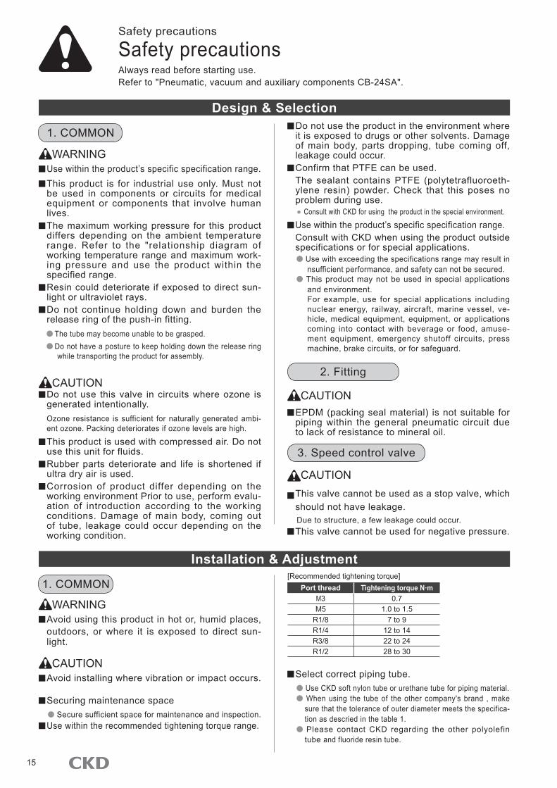
Do not use the product in the environment where it is exposed to drugs or other solvents. Damage of main body, parts dropping, tube coming off, leakage could occur. Confirm that PTFE can be used.The sealant contains PTFE (polytetrafluoroeth-ylene resin) powder. Check that this poses no problem during use.● Consult with CKD for using the product in the special environment.
Use within the product’s specific specification range.Consult with CKD when using the product outside specifications or for special applications.
Use with exceeding the specifications range may result in nsufficient performance, and safety can not be secured.
This product may not be used in special applications and environment.For example, use for special applications including nuclear energy, railway, aircraft, marine vessel, ve-hicle, medical equipment, equipment, or applications coming into contact with beverage or food, amuse-ment equipment, emergency shutoff circuits, press machine, brake circuits, or for safeguard.
CAUTION EPDM (packing seal material) is not suitable for piping within the general pneumatic circuit due to lack of resistance to mineral oil.
CAUTION This valve cannot be used as a stop valve, which should not have leakage.Due to structure, a few leakage could occur. This valve cannot be used for negative pressure.
Select correct piping tube. Use CKD soft nylon tube or urethane tube for piping material. When using the tube of the other company's brand , make sure that the tolerance of outer diameter meets the specifica-tion as descried in the table 1. Please contact CKD regarding the other polyolefin tube and fluoride resin tube.
Safety precautions
Always read before starting use.Refer to "Pneumatic, vacuum and auxiliary components CB-24SA".
Safety precautions
Design & Selection
Installation & Adjustment
WARNING Use within the product’s specific specification range. This product is for industrial use only. Must not be used in components or circuits for medical equipment or components that involve human lives. The maximum working pressure for this product differs depending on the ambient temperature range. Refer to the "relationship diagram of working temperature range and maximum work-ing pressure and use the product within the specified range. Resin could deteriorate if exposed to direct sun-light or ultraviolet rays. Do not continue holding down and burden the release ring of the push-in fitting.
The tube may become unable to be grasped. Do not have a posture to keep holding down the release ring
while transporting the product for assembly.
CAUTION Do not use this valve in circuits where ozone is generated intentionally.Ozone resistance is sufficient for naturally generated ambi-ent ozone. Packing deteriorates if ozone levels are high.
This product is used with compressed air. Do not use this unit for fluids. Rubber parts deteriorate and life is shortened if ultra dry air is used. Corrosion of product differ depending on the working environment Prior to use, perform evalu-ation of introduction according to the working conditions. Damage of main body, coming out of tube, leakage could occur depending on the working condition.
WARNING Avoid using this product in hot or, humid places, outdoors, or where it is exposed to direct sun-light.
CAUTION Avoid installing where vibration or impact occurs.
Securing maintenance space Secure sufficient space for maintenance and inspection.
Use within the recommended tightening torque range.
1. COMMON
1. COMMON
2. Fitting
3. Speed control valve
[Recommended tightening torque]Port thread Tightening torque N·m
M3 0.7M5 1.0 to 1.5
R1/8 7 to 9R1/4 12 to 14R3/8 22 to 24R1/2 28 to 30

16
ZSF/SC3F/SCLF SeriesCautions
Tolerance of tube outer diameterType of tube Tolerance of dimensionsUrethane tube Nominal diameter ±0.15
Nylon tube Nominal diameter ±0.1
Securely insert the tube to the tube end, and make sure that the tube cannot be pulled off.
Cut the tube at a right angle using the dedicated cutter and make sure that there is no scratch on the outer diameter of the tube and the tube is not shaped like an ellipse.
Remove all swarf and foreign materials generated dur-ing piping and tube insertion before starting use.
Provide sufficient allowance in the tube so that it does not bent suddenly.
Do not reuse a tube that could be deteriorated and de-formed.
Flush and wash pipes to be used. Dirt or foreign materials in piping will lower product performance.
Use an insert ring for the tube internal diameter of the mounting side when a soft tube is used for push-in fitting. If not, the tube could come off or leakage could occur. When supplying compressed air after piping is completed, make sure that there is no leakage on the all pipe connections.Apply a leakage detection agent on pipe connections with a brush, and check for air leaks. Pipe so that piping connections do not become dislocated due to device movement, vibration, or tension. Securely insert the tube until it contacts the joint's tube end, and check that it does not come off the joint. Do not tighten while pressure is applied. Avoid use in applications involving continuous turning or swaying.
Otherwise the joint could be damaged. Cut the tube when the hard tube is repeatedly mounted and removed and used. The surface of the tube tends to scar easily due to the dif-ference in surface hardness, which could cause leakage. Do not repeatedly mount and remove the resin plug. The surface tends to scar easily and could cause leakage. Do not use a metal plug, which causes trouble.
CAUTION
Mounting and removal of the tube becomes tight-er than the standard type due to the grease free specification. Make sure that the tube is inserted all the way to the end of the tube before use. Ap-plying liquid which does not cause problems with use improve the installation effectiveness. Tighten the mounting nut of the bulkhead union with the fol lowing recommended t ightening torque. When used for a long time or in the high temperature environment, the screw could get loosen due to change in creep shape. Regular-ly inspect and retighten with the recommended tightening torque. If retightening did not improve the looseness, replace it with a new one.[Recommended tightening torque]
Port thread
Tightening torque N·m
M12 0.5 to 0.7M14 0.7 to 0.9M16 0.8 to 1.0M20 1.5 to 1.9M24 2.2 to 2.8
CAUTION Check that lock nuts are not loose. Check the number of turns for the needle valve used.
The needle valve has dislocation prevention that could bite or break if the needle is turned too far. Check the number of rotation for the product used.
Ful ly close the needle, and open to adjust speed.
The needle opens when turned to the right and closes when turned to the left.
Install an air filter in front of the circuit.The flow varies depending on clogging or foreign matters adhered in the orifice. Check the flow direction and connect correctly.
Do not tighten while pressure is applied. Although installation by rotating arbitrary direction is enabled, do not use for the purpose of constant rota-tion and vibration.
If the product has a lock nut, securely tighten the nut by hand instead of using a tool. The lock nut or main unit could be damaged if the lock nut is tightened with a tool. If the lock nut is not accu-rately tightened, it could loosen and cause initial settings to deviate.
3. Speed control valve
2. Fitting
CAUTION During maintenance, stop supplying flow and check that no residual pressure remains. Storage
Do not leave the product in a hot or highly humid at-mosphere or outside of the specified range for a long time. This causes deterioration of resin and rubber.
Consult with CKD when storing this unit outside specifications.
During Use & Maintenance
WARNING Use within the maximum service pressure and maximum working pressure difference range.
1. COMMON

17
MEMOMEMOMEMOMEMO

18
ZSF/SC3F/SCLF SeriesRelated products
Catalog No.CC-947A
Catalog No.CC-1012 (Jpn.)
Related products
We offer a wide range components for the safe manufacturing process of secondary batteries.
Introduced push-in fitting SUS303 equivalent product with use of stainless steel in the metal body section for secondary battery manufacturing equipment with limitation of copper material use, semiconductor, which dislikes particle occurrence due to corrosion, and FPD manufacturing equipment A wide variety of models
Wide variation available for each type of pneumatic pressure piping Ecological products
All substances that can adversely affect the environ-ment have been eliminated from the materials
RoHS directive compliant product
Components for secondary battery production P4* Series
Fitting stainless type ZW-P4 Series
Components for Secondary Battery ProductionP4* Series
Building a sustainable future with technology
CC-947A 7
Applicable components from clean air components to actuators.
Applicable components from clean air components to actuators.
Tried, tested and used in our winding machinesTried, tested and used in our winding machines
CKD’ s Li-ion battery winding machine Wide range of additional components!!

● Specifications are subject to change without notice.
The goods and their replicas, or the technology and software in this catalog are subject to complementary export regulations by Foreign Exchange and Foreign Trade Law of Japan.If the goods and their replicas, or the technology and software in this catalog are to be exported, laws require the exporter to make sure they will never be used for the development or the manufacture of weapons for mass destruction.
2011.8.CACCKD Corporation 2011 All copy rights reserved.©
U.S.A.CKD USA CORPORATION● HEADQUARTERS
4080 Winnetka Avenue, Rolling Meadows, IL 60008 USAPHONE +1-847-368-0539 FAX +1-847-788-0575
EUROPECKD EUROPE BRANCH
De Fruittuinen 28 Hoofddorp 2132NZ The NetherlandsPHONE +31- (0) 23-5541490 FAX +31- (0) 23-5541491
MalaysiaM-CKD PRECISION SDN.BHD.● HEADQUARTERS
Lot No.6,Jalan Modal 23/2, Seksyen 23, Kawasan, MIEL,Fasa 8, 40300 Shah Alam,Selangor Darul Ehsan, MalaysiaPHONE +60- (0) 3-5541-1468 FAX +60- (0) 3-5541-1533
ThailandCKD THAI CORPORATION LTD.● SALES HEADQUARTERS-BANGKOK OFFICE
Suwan Tower, 14/1 Soi Saladaeng 1, North Sathorn Rd., Bangrak, Bangkok 10500 ThailandPHONE +66- (0) 2-267-6300 FAX +66- (0) 2-267-6305
SingaporeCKD SINGAPORE PTE. LTD.
No.33 Tannery Lane #04-01 Hoesteel Industrial Building Singapore 347789 PHONE +65-67442623 FAX +65-67442486
CKD CORPORATION BRANCH OFFICENo.33 Tannery Lane #04-01 Hoesteel Industrial Building Singapore 347789 PHONE +65-67447260 FAX +65-68421022
TaiwanTAIWAN CKD CORPORATION
16F-3,No.109,Sec.1Jhongshan RD.,Shinjhuang Dist., New Taipei City, 24250,Taiwan(R.O.C)PHONE +886- (0) 2-8522-8198 FAX +886- (0) 2-8522-8128
ChinaCKD (SHANGHAI) CORPORATION● SALES HEADQUARTERS / SHANGHAI OFFICE
Room 601,Yuan Zhong Scientific Reseach Building,1905 Hongmei Road,Shanghai, 200233, ChinaPHONE +86- (0) 21-61911888 FAX +86- (0) 21-60905356
KoreaCKD KOREA CORPORATION● HEADQUARTERS
3rd FL, Sam Young B/D, 371-20Sinsu-Dong, Mapo-Gu, Seoul, 121-110, KoreaPHONE +82- (0) 2-783-5201 to 5203 FAX +82- (0) 2-783-5204
OVERSEAS SALES ADMINISTRATION DPT.OVERSEAS BUSINESS DIV. 2-250 Ouji Komaki, Aichi 485-8551, JapanPHONE +81-(0)568-74-1338 FAX +81-(0)568-77-3461
Website http://www.ckd.co.jp/
TAIWAN CKD CORPORATION● HSINJHU OFFICE
M-CKD PRECISION SDN.BHD.
CKD USA CORPORATION
CKD UK OFFICE
CKD EUROPE BRANCH
CKD GERMAN OFFICE
CKD CZECH OFFICE
CKD KOREA CORPORATION
CKD SINGAPORE PTE. LTD.CKD CORPORATION BRANCH OFFICE
● CINCINNATI OFFICE● SAN ANTONIO OFFICE● SAN JOSE OFFICE
● JOHOR BAHRU OFFICE● MELAKA OFFICE● PENANG OFFICE
● SUWON OFFICE
CKD THAI CORPORATION LTD.● RAYONG OFFICE● NAVANAKORN OFFICE● EASTERN SEABORD OFFICE● LAMPHUN OFFICE● KORAT OFFICE● AMATANAKORN OFFICE
CKD CORPORATIONINDIA LIAISON OFFICE(Bangalore,Delhi)
: Distributors
● SHANGHAI OFFICE● BEIJING OFFICE● TIANJIN OFFICE● WUXI OFFICE● NANJING OFFICE● CHONGQING OFFICE
● CHANGSHA OFFICE● CHENGDU OFFICE● XIAN OFFICE● SHENGYANG OFFICE● CHANGCHUN OFFICE● DALIAN OFFICE
● SHENZHEN OFFICE● GUANGZHOU OFFICE● HANGZHOU OFFICE● WUHAN OFFICE● SUZHOU OFFICE● QINGDAO OFFICE
● XIAMEN OFFICE● DONGGUAN OFFICE● KUNSHAN OFFICE● JINAN OFFICE● NINGBO OFFICE
CKD(SHANGHAI) CORPORATION