Embed Size (px)
Citation preview
Process Modelling & Optimisation Group
Fischer Tropsch Development using COCO and Ansys
by
Vidushi Chitranshi, Dr. Klaus Moller and Dr. Ryno Laubscher
University of Cape Town, Cape Town, South Africa
27th October 2021
Process Modelling & Optimisation Group
What is Fischer Tropsch Synthesis?
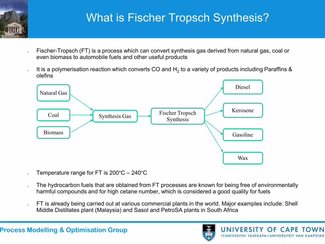
o Fischer-Tropsch (FT) is a process which can convert synthesis gas derived from natural gas, coal or even biomass to automobile fuels and other useful products
o It is a polymerisation reaction which converts CO and H2 to a variety of products including Paraffins & olefins
o Temperature range for FT is 200°C – 240°C
o The hydrocarbon fuels that are obtained from FT processes are known for being free of environmentally harmful compounds and for high cetane number, which is considered a good quality for fuels
o FT is already being carried out at various commercial plants in the world. Major examples include: Shell Middle Distillates plant (Malaysia) and Sasol and PetroSA plants in South Africa
Coal
Natural Gas
Biomass
Synthesis GasFischer Tropsch
Synthesis
Diesel
Kerosene
Gasoline
Wax

Process Modelling & Optimisation Group
Conventional Techniques and their Issues
o Conventionally, multi tubular reactors were employed, wherein catalyst particles filled in tube, and syngas is passed through the bed of particles, to react and form products
Figure : Schematic diagram for a Multitubular Fixed bed reactor, reproduced from (Guettel, Kunz and Turek, 2008)
o The issue with the conventional reactors is the temperature runaway caused due to extreme exothermicity of this reaction. High temperature destroys the catalyst particles. Selectivity to undesired products also increases.

Process Modelling & Optimisation Group
Plate Type Reactors
o Innovative Reactor configuration techniques have been explored in literature, but not in detail
o If different types of heat exchangers (HE) are to be compared, plate type HEs are better than the conventional shell and tube HEs in terms of heat transfer properties among all other advantages.
o Taking an idea from this, a computational study was carried out to explore the potential of Plate type reactors over the conventional tube reactors
o A plate type reactor has catalyst particles squeezed between two plates with steam as a cooling medium on either sides, with syngas passing through catalyst particles
o A model was constructed in COCO and ANSYS, a CFD software for the plate and tube geometries.
o Since, a plate geometry is not directly possible to create in COCO, heat transfer coefficients in COCO were tuned with the help of Ansys plate type 2D models to represent the plate type reactors in COCO

Process Modelling & Optimisation Group
Kinetics
Lumped Approach
o Assumption: Products have no role inmonomer formation; so rate expressions arepostulated to describe consumption rate ofreactants only
o Chain reaction is not considered
o Product distribution models are used to describeproduct selectivity
o It is much simpler and convenient to use
o All reactions are parallel and independent,hence not suitable to predict thermal behaviour,mass transfer & VLE
o There have been several deviations observedfrom literature in the actual experimental data
o Hence, it is unreliable
Partial Equilibrium Approach
o It involves proposing a reaction mechanismdeveloping kinetic expressions based on those.
o Reaction rates are dependent on reactants aswell as all the products, hence all reactions areinterdependent
o Due to all the interdependence, it is prettycomplex to implement, but it definitely gives amore realistic picture compared to the lumpedapproach
o Unlike the lumped approach, in this approachthe thermodynamics and the kinetics arecoupled and dependent on each other

Process Modelling & Optimisation Group
Imaad’s Kinetics Model
o The kinetic model employed in this project has been taken from the work of Davies and Möller, 2021.
o The reaction mechanism involves a chain initiation, propagation and termination steps
o The chain monomer is CH2 which is a pseudo specie and is formed by hydrogenation of CO.
Figure: Proposed reaction pathway, adapted from (Fernandes, 2005) (Schulz, Steen and Claeys, 1994)
o Water Gas Shift Reaction was not considered in the model because its importance is insignificant for cobalt catalyst

Process Modelling & Optimisation Group
Ansys Model
o The model geometry represents a single tube reactor and a plate type reactor. The dimensions for the reactor, the catalyst specifications and operating conditions were taken from the work of Jess and Kern, (2012)
o Dimensions: Length 12m, Diameter – 4 cm
o Porous zone between the catalyst particles was accounted for by implementing a pressure drop according to the Ergun Equation.
o A total of 43 species were considered, including reactants and products: Paraffins: C1 – C20 and Olefins: C2 – C20

Process Modelling & Optimisation Group
COCO Model
o The COCO model employed the same geometry dimensions, kinetics and operating conditions as that of Ansys
o It was a big challenge to create single rate expression from the huge interdependent kinetics into a single expression, the way COCO allows the users to input the reaction rate in GUI for each reaction (a total of 39 reactions). The single rate expression for each rxn came out to be 1 page long.
o Other softwares (Ansys & Scilab) didn’t pose such a problem because of provision of ‘notepad like platform’ Scinotes in Scilab and User-Defined Functions (UDF) in Ansys respectively to code the whole kinetics function

Process Modelling & Optimisation Group
(Contd.)
o Despite the challenges related to kinetics, the model was successfully run at 3 different platforms Ansys, COCO and Scilab
o Kinetic model was verified first at isothermal conditions followed by non-isothermal conditions.
o The major difference between COCO and Ansys models are the following:
❖ COCO has a 1D model, which means all the radial variations in species, energy transfer were neglected; while Ansys has a 2D CFD model, meaning axial as well as radial variations were both considered
❖ Real gas behaviour (Peng-Robinson EOS) is considered in COCO, while in Ansys ideal gas behaviour assumption was taken
Process Modelling & Optimisation Group
Model Verification (Isothermal Case)
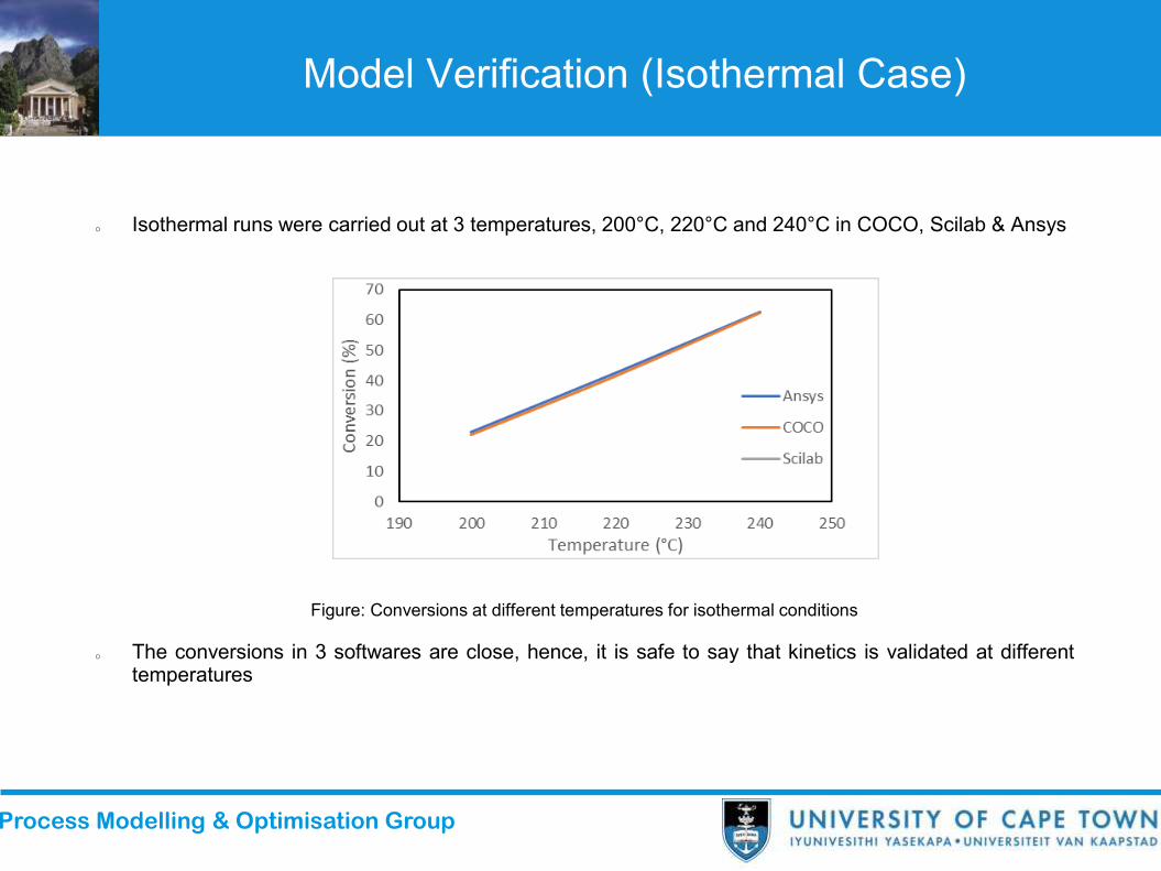
o Isothermal runs were carried out at 3 temperatures, 200°C, 220°C and 240°C in COCO, Scilab & Ansys
Figure: Conversions at different temperatures for isothermal conditions
o The conversions in 3 softwares are close, hence, it is safe to say that kinetics is validated at differenttemperatures

Process Modelling & Optimisation Group
Model Verification (Heat Transfer Case)
o Simulation runs were carried out at 3 temperatures, 200°C, 220°C and 240°C in COCO and Ansys
o The graphs show hotspot temperatures and conversions observed for Ansys and COCO at differenttemperatures
o For conversion as well as hotspot temperature, Ansys and COCO seem close enough to verify themodel for heat transfer
Process Modelling & Optimisation Group
Results - COCO vs. Ansys
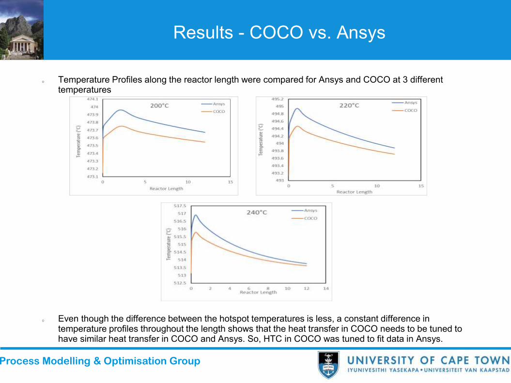
o Temperature Profiles along the reactor length were compared for Ansys and COCO at 3 different temperatures
o Even though the difference between the hotspot temperatures is less, a constant difference in temperature profiles throughout the length shows that the heat transfer in COCO needs to be tuned to have similar heat transfer in COCO and Ansys. So, HTC in COCO was tuned to fit data in Ansys.

Process Modelling & Optimisation Group
Product Distribution
o Carbon number 1 -20 Paraffins, 21-39- Olefins
o After tuning the heat transfer coefficients in COCO, the heat transfer profiles in Ansys and COCO were similar, but the product distributions still showed considerable differences
o The reason behind the deviations are not yet fully known. Possible reasons include, the inclusion of radial effects in Ansys in contrast to the COCO, where only axial variations were accounted for. The radial mixing of the species might have an impact on the specie concentrations which in turn affect the selectivities

Process Modelling & Optimisation Group
Tube vs. Plate
o The tube geometry was modelled as a cuboid having the same length as the tube geometry (12m) and a width of 1m, while the spacing between the plates (t) was 4 cm.
Criteria for Comparison:
1. The Surface to volume ratio in both the geometries was kept same.
2. The hydraulic diameter was kept the same for both geometries, which resulted in same Reynolds number.
These two criteria resulted in a relation between the diameter and plate spacing:
D = 2t

Process Modelling & Optimisation Group
(Contd.)
From the comparison between the results of two geometries and the graphs on previous slides, it can be concluded that:
1. The Plate geometries can go upto larger plate spacings without having a temperature runaway compared to the tube geometries of same radius, which means as radius and plate spacing increase in the both the geometries, a tube reactor attains a thermal runaway before the plate type reactor
2. For same radius and plate spacing, a tube reactor experiences much higher hotspot temperature than a plate type reactor
3. For same radius and plate spacing, more conversion was achieved in tube geometries than the plate geometries
These results can be confirmed by the parametric analysis in the next slide.

Process Modelling & Optimisation Group
Parametric Analysis
o Temperature profiles were obtained for different diameters along the reactor length for the tube geometry and the plate geometry on ansys:

Process Modelling & Optimisation Group
Plate Representation in COCO
o Since plate geometries can not be directly created in COCO, an direct way to represent these geometries by modifying the heat transfer coefficients such that the hotspot temperatures in Ansys and COCO match, was adopted.
o The following graph shows conversion at different plate spacing (Ansys) or tube radius (COCO):
o From, the graph it can be observed that conversions in COCO and Ansys do not differ by large amounts. Hence, COCO can be used to represent plate type geometries along with the cylindrical geometries.

Process Modelling & Optimisation Group
Conclusion
Following conclusions were drawn:
1. A complex kinetics was reduced to a single expression and inputted in COCO to model a FT reactor for 43 species. The model showed good verification with other numerical results obtained thorough Ansys and Scilab for Isothermal and non-Isothermal conditions
2. Heat transfer coefficient in COCO was tuned to fit the data related to Temperature obtained from Ansys. Even after tuning the HTC, the product distribution in COCO shows huge deviations from the Ansys distribution. The reasons behind this observation is not yet fully understood. Possible reasons include the neglection of the radial effects in COCO.
3. HTC values were tuned to fit the data for the plate type reactors obtained from Ansys to represent a plate type reactor in COCO. The conversion values in COCO showed good verification with the Ansys conversion values. Hence the tuned COCO model can be used to represent a plate type reactor.

Process Modelling & Optimisation Group
References
Guettel, R., Kunz, U. and Turek, T. (2008) ‘Reactors for Fischer-Tropsch Synthesis’, Chemical Engineering & Technology: Industrial Chemistry-Plant Equipment-Process Engineering-Biotechnology. Wiley Online Library, 31(5), pp. 746–754.
Davies, I. and Möller, K. P. (2021b) ‘Development of a kinetic model for low temperature Fischer-Tropsch synthesis’, Chemical Engineering Science, 241(October). doi: 10.1016/j.ces.2021.116666.
Jess, A. and Kern, C. (2009) ‘Modeling of multi-tubular reactors for Fischer-Tropsch synthesis’, Chemical Engineering and Technology, 32(8), pp. 1164–1175. doi: 10.1002/ceat.200900131.

Process Modelling & Optimisation Group
Thank you!