Embed Size (px)
Citation preview
A.1-Draft
ADDENDUM - EXXON FISCHER-TROPSCH WORK
Fischer Synthesis Process
A patent (A.1), a continuation of four prior applications with the first dated
October 3, 1989, claimed a method for hydrocarbon synthesis reactions. This patent
relates to the use of a catalyst of the "rim" type, as the terminology is used by Exxon.
These are catalysts where the active metal(s) are deposited in the outermost layer of
the support particle, and in a mannor that the interior of the support particle is
essentially devoid of the metal(s). This approach is widely used in the manufacturer of
auto exhaust catalysts that are shaped into spheres, cylinders, etc. The specific
experiments were conducted with a 6 wt.% cobalt and 0.5 wt.% ruthenium on silica or
titania support; since the surface area of the catalyst used in the example was reported
to be about 20 m2/g it is assumed that the support was titania. The description of the
preferred embodiment includes a derivation of the theoretical aspects of the
determination of the rim loaded thickness needed to optimize CO conversion and/or
minimize methane production. This theory has been included in several of the reviews
of Fischer-Tropsch synthesis that have recently been published by Exxon workers. It is
surprising that the authors of these reviews are not inventors of this method for
hydrocarbon synthesis reactions and that the inventor (M. Herskowitz) is not an author
of the review articles.
The outer layer containing the catalytic metal has a thickness determined so as
to optimize CO conversion to heavy hydrocarbons so that conversion to methane is
maintained at a predetermined level. The inventor maintains that it is not possible to
simultaneously maximize CO conversion and minimize methane conversion. However
it is possible to define a rim thickness so as to optimize one of these products. The

A.2-Draft
thickness of the rim-loaded catalyst is determined by relating the rate of diffusion of CO
and H2 to a rate of reaction in the porous inorganic oxide for a predetermined support
geometry, partial pressures and temperatures.
The fluxes of the two reactants at steady state must be equal since there is no
accumulation; thus,
ßDe,CO [dCCO/d?] = De,H [dCH/d?] [A.1]
where the flux is expressed as a product of the effective diffusivity, De, and the
concentration gradient. ß is the stoichiometric coefficient and is equal to 2.07 in the
reported work. Since hydrogen diffuses more rapidly than CO, the relative
concentration of hydrogen should increase from the surface to the center of the
catalyst pellet.
The differential mass balance inside the pores of the catalyst pellet of carbon
monoxide, the limiting reactant, is
[De,CO (1/?s)] d/d?[?s (dCCO/d?)] = ?prCO [A.2]
where ? is the radial position measured from the external surface toward the center, ?p
is the pellet density, CCO is the CO concentration in the liquid-filled pores and rCO is the
intrinsic rate of reaction on the active sites. The shape factor, s, is equal to two for a
sphere and to unity for a cylinder; the treatment can be extended to other pellet
shapes.
The boundary condition on the external surface is:
CCO = PCO,b/HCO [A.3]
where PCO,b is the CO partial pressure in the bulk gas phase and HCO is the Henry's
Law constant. The other boundary condition can be defined for two cases as:
inert core dCCO/d ? = 0 ? = ?i [A.4]
A.3-Draft
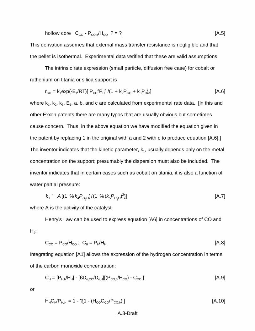
hollow core CCO - PCO,b/HCO ? = ?i [A.5]
This derivation assumes that external mass transfer resistance is negligible and that
the pellet is isothermal. Experimental data verified that these are valid assumptions.
The intrinsic rate expression (small particle, diffusion free case) for cobalt or
ruthenium on titania or silica support is
rCO = k1exp(-E1/RT)[ PCOaPH
b /(1 + k2PCO + k3PH)c] [A.6]
where k1, k2, k3, E1, a, b, and c are calculated from experimental rate data. [In this and
other Exxon patents there are many typos that are usually obvious but sometimes
cause concern. Thus, in the above equation we have modified the equation given in
the patent by replacing 1 in the original with a and 2 with c to produce equation [A.6].]
The inventor indicates that the kinetic parameter, k1, usually depends only on the metal
concentration on the support; presumably the dispersion must also be included. The
inventor indicates that in certain cases such as cobalt on titania, it is also a function of
water partial pressure:
[A.7]k1 ' A [(1 % k4PH2O) /(1 % (k5PH2O)2)]
where A is the activity of the catalyst.
Henry's Law can be used to express equation [A6] in concentrations of CO and
H2:
CCO = PCO/HCO ; CH = PH/HH [A.8]
Integrating equation [A1] allows the expression of the hydrogen concentration in terms
of the carbon monoxide concentration:
CH = [PH,b/HH] - [ßDe,CO/De,H][(PCO,b/HCO) - CCO ] [A.9]
or
HHCH/PH,b = 1 - ?[1 - (HCOCCO/PCO,b) ] [A.10]
A.4-Draft
where
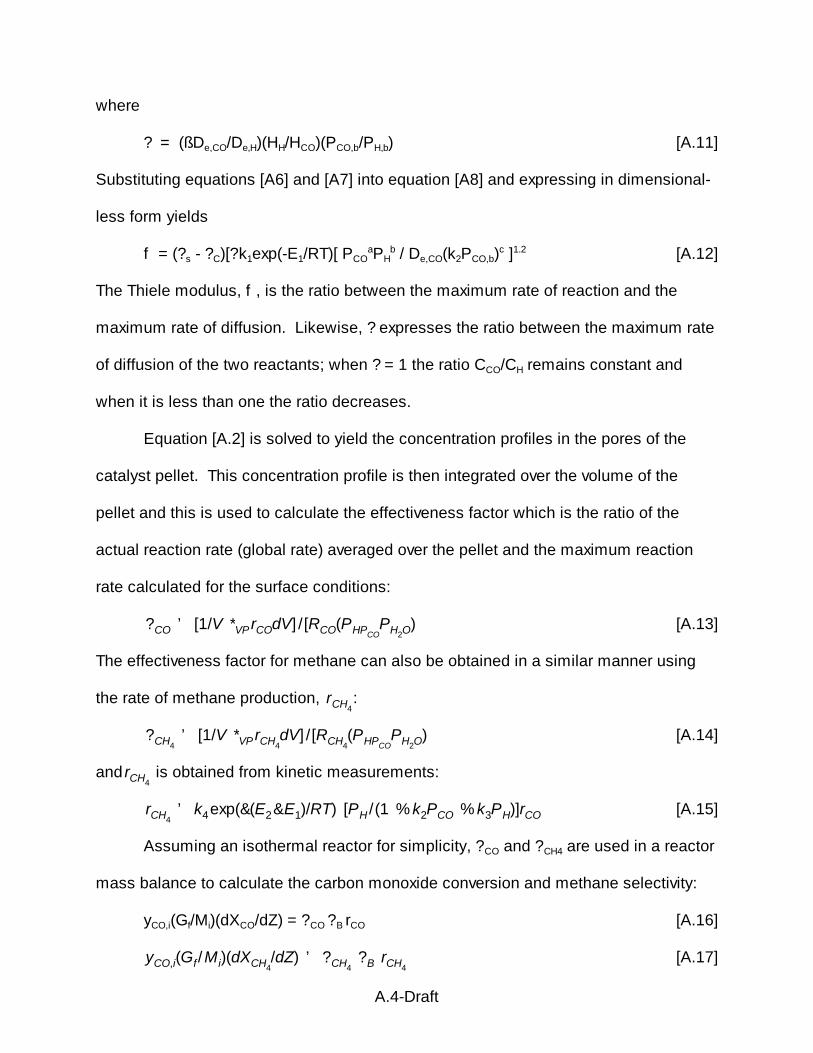
? = (ßDe,CO/De,H)(HH/HCO)(PCO,b/PH,b) [A.11]
Substituting equations [A6] and [A7] into equation [A8] and expressing in dimensional-
less form yields
f = (?s - ?C)[?k1exp(-E1/RT)[ PCOaPH
b / De,CO(k2PCO,b)c ]1.2 [A.12]
The Thiele modulus, f , is the ratio between the maximum rate of reaction and the
maximum rate of diffusion. Likewise, ? expresses the ratio between the maximum rate
of diffusion of the two reactants; when ? = 1 the ratio CCO/CH remains constant and
when it is less than one the ratio decreases.
Equation [A.2] is solved to yield the concentration profiles in the pores of the
catalyst pellet. This concentration profile is then integrated over the volume of the
pellet and this is used to calculate the effectiveness factor which is the ratio of the
actual reaction rate (global rate) averaged over the pellet and the maximum reaction
rate calculated for the surface conditions:
[A.13]?CO ' [1/V *VP rCOdV] /[RCO(PHPCOPH2O)
The effectiveness factor for methane can also be obtained in a similar manner using
the rate of methane production, :rCH4
[A.14]?CH4' [1/V *VP rCH4
dV] /[RCH4(PHPCO
PH2O)
and is obtained from kinetic measurements:rCH4
[A.15]rCH4' k4exp(&(E2&E1)/RT) [PH /(1 % k2PCO % k3PH)]rCO
Assuming an isothermal reactor for simplicity, ?CO and ?CH4 are used in a reactor
mass balance to calculate the carbon monoxide conversion and methane selectivity:
yCO,i(Gf/Mi)(dXCO/dZ) = ?CO ?B rCO [A.16]
[A.17]yCO,i(Gf /Mi)(dXCH4/dZ) ' ?CH4
?B rCH4

A.5-Draft
where YCO,i is the carbon monoxide mole fraction in the feed, Gf is the mass velocity, Mi
is the molecular weight of the feed, ?B is the bed density and XCO and are theXCH4
carbon monoxide and methane conversion, respectively.
Using a 6% Co/0.5% Re catalyst of different pellet sizes and a feed with H2/CO
= 2, the CO conversion and CH4 selectivity were measured. These conversion data
were used to estimate the CO and H2 diffusivities using the following procedure:
a. values of De,CO and De,H were assumed;
b. effectiveness factors ?CO and were calculated from equations [A.9] and?CH4
[A.10] and the solution of equation [A.2] given the inlet conditions of the reactor;
c. the CO conversion and conversion to methane were calculated by integrating
equations [A.16] and [A.17]; since the effectiveness factors are functions of the
partial pressures of CO, CH4 and H2O they must be recalculated along the
length of the reactor taking into account of the changes in the partial pressures;
d. methane selectivity was calculated from the ratio of conversion to methane,
and carbon monoxide conversion, XCO;XCH4
e. the calculated carbon monoxide conversion and the methane selectivity were
compared with the experimental values for the various pellet sizes; and
f. the effective diffusivities are adjusted to give the best fit of the experimental data.
An example of the agreement between the calculated and the experimental data
for catalysts with a range of diameters is shown in A.1.
In one example the experiments were performed in a 3'x0.5" reactor that was
packed with 1 mm diameter spherical particles uniformly loaded with 6%Co-0.5%Re.
Data were obtained as the reaction temperature and the H2/CO ratio were varied and
the CO conversion and CH4 selectivity obtained as described above. When the initial

A.6-Draft
H2/CO ratio is less than 2, the ratio will decrease along the catalyst bed and, since
methane selectivity depends upon this ratio, it will decrease down the bed.
Simulations of carbon monoxide conversion and methane selectivity were made
for various thickness of the rim loaded metals. As shown in A.2, both conversion
and methane selectivity increase with increasing rim thickness. However, the
important point is that these two factors increase rapidly from a low to high value and
that the rim thickness where this increase occurs is different for the two factors.
In another simulation, the carbon monoxide conversion and methane selectivity
were determined for two pellet shapes: ring and cylinder. As shown in A.3, the
rim thickness needed to obtain the maximum CO conversion and a low methane
selectivity depends upon the pellet shape. Thus, the cylindrical shape provides a much
greater difference between the rapid increase in the two factors than the ring shape
does.
The inventor claims a method for making a catalyst by determining the rim
thickness which optimizes both the rate of carbon monoxide hydrogenation and the
reduction of methane selectivity.
Long (A.2,A.3) claims a substantially once-through hydrocarbon synthesis
process which comprises reacting in a first reactor or stages, a feed comprising
hydrogen and carbon monoxide, and optionally CO2, in the presence of a non-shifting
hydrocarbon synthesis catalyst. The effluent is treated to recover the product from the
first reactor by condensing the liquids and then reacting the remaining gases in a
subsequent stage or stages in the presence of a hydrocarbon synthesis catalyst having
shift activity, producing and recovering additional products.

A.7-Draft
A basis for this invention is that "The shift reaction can, however, be suppressed
if the feed contains higher amounts of CO2 relative to CO, and CO2 is known to be
added to H2 + CO synthesis gas feeds for hydrocarbon synthesis. Synthesis gas feeds
can contain up to 10% CO2, that is, about 0.1-10% CO2." The feed to the first stage(s)
has H2/CO in a 1.5:1 to 1.5:1 mole ratio, preferably 1.9: to 2.3:1, and CO2 in the range
1.0-10 mole%, preferably 5-10 mole%. This mixture is subjected to synthesis with a
non-shifting catalyst, preferably cobalt on alumina, silica or titania (preferred), and
preferably promoted by metals as Ru, Rh, Ce or Hf, most particularly Rh (A.4).
Conversion of CO in the first stage(s) are preferably at least 90%. Following
conversion by the non-shifting catalyst, the liquid products, containing C5+
hydrocarbons, water, oxygenated compounds and small amounts of dissolved gases.
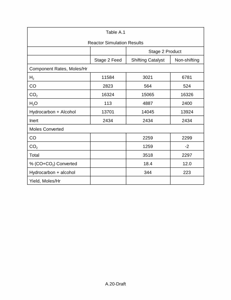
The feed for the stage 2 reactor(s) with shift catalyst is illustrated in A.1.
Based on our calculations, the mole fraction of water in the feed is 0.0024 (1.83 mm if
operating at 20 atm). For a water-vapor saturated stream, we estimate the
temperature of the separation to be -10 to -15oC, a surprisingly low temperature. The
gas shown in A.1 is fed to a stage 2 reactor(s) where subsequent hydrocarbon
synthesis produces a product with an olefin:paraffin ratio of 1.5:1 to 4:1, the lower
ratios being favored for higher hydrocarbons and the higher ratios favored for the lower
carbon number hydrocarbons. The H2/CO ratio entering the stage 2 reactor(s) will be
essentially the same as the stage 1 reactor(s) because of the non-shifting character in
the stage 1 operations. However, because of the conversion in stage 1 reactor(s), less
gas will enter stage 2 reactor(s) with the result that the relative concentration of CO2
will be higher in stage 2 than in stage 1 reactors. Sufficient hydrogen must be present
in the feed to stage 2 reactor(s) to react with both CO and CO2. Reaction conditions in

A.8-Draft
stage 2 reactor(s) will be similar to those in stage 1 reactor(s); e.g., 10-35 bar, 220-
340o, SHSV 200-2000 dry feed (water less than 5 vol% of feed).
Slurry Reactor
Herbolzheimer et al. (A.5) claim the use of a second solid in a slurry phase
hydrocarbon synthesis process. A gas is injected at or near the bottom of the bubble
column containing a slurry liquid, a catalytically active first solid and at least a second
solid. The energy to maintain the dispersion of the solids is supplied by the gas in the
absence of liquid recycle. The second solid is added in sufficient quantity to increase
the bed height by at least 10%.
The authors state that slurry phase reaction, particularly those occurring in
bubble columns, are well-known and do not need to be discussed. In column 6, line
23, the authors state that, "Slurry reactors are well known..." This is surprising since it
would appear to imply that at the time of filing this patent [February 25, 1991] the use
of slurry reactions are well known and, since bubble column reactors are also well
known, only specific improvements to the operation of slurry bubble column reactors
should be patentable inventions. Catalyst settling is a problem that can be
encountered in bubble column reactors. Particles tend to settle to the bottom because
of the influence of gravity. Opposing the settling tendency is the dispersion forces
created by the rising bubbles of gas injected at or near the bottom of the reactor. The
balancing effect of these two forces results in an exponential distribution of catalyst
solids concentration.
The authors utilize the data employing a dispersion coefficient and the settling
velocity. D, the dispersion coefficient, depends on the superficial gas velocity through
the system and on the effective diameter of the reactor column. The authors do not
A.9-Draft
define this term in more detail, and presumably are considering the dispersion
coefficient for the solids. The settling velocity of the catalyst particles, Us, is given as
Us = Uo(1 - c)n [A.18]
where
Uo = dp2(?s - ?)g/18F [?s is given as ?s in the patent] [A.19]
where c is the volume fraction of solids in the slurry, dp is the particle diameter, ?s is
the density of the solids, g is the gravitational constant, F is the viscosity of the
suspending liquid, and n is a constant ranging from 4 to 8.
In the description, they indicate that most reactors operate in a regime
somewhere between plug-flow and fully-backmixed (or CSTR) conditions. A plug-flow
condition can be attained by using fixed-bed catalyst or a very large L/d (where L and d
are the length and effective diameter of the reactor, respectively). In the plug-flow
reactor the concentration (or partial pressure) of hydrogen and carbon monoxide, the
reactants for Fischer-Tropsch Synthesis, decrease along the path of reactor flow due to
reaction, and this decreases the driving force of the reaction. On the contrary,
complete backmixing results in the same concentration of reactants along the entire
length of the reactor resulting in a constant driving force and reflects the relatively low
driving force at exit conditions.
Productivity is generally favored in plug-flow systems and selectivity is favored in
backmixed systems. Later Exxon patents pertain to the operating conditions for plug-
flow bubble column slurry reactors .
In the preferred mode for this patent, there ia an absence of liquid throughput;
thus, in the preferred mode, all of the energy from maintaining solids as a dispersion in
the liquid is provided by the injection of gas at or near the bottom of the slurry reactor.
A.10-Draft
The catalysts utiliized in the examples are typical of those described in many
Exxon, and other, patents. The preferred catalyst is cobalt supported on titania and
promoted with rhenium. The preferred catalyst particle size is in the range of 20 to 100
microns.
The data described in the examples were obtained in a 5 meter tall, non-reactive
bubble column with 15 cm internal diameter (i.e., the L/d ratio was greater than 20,
corresponding to nearly plug-flow conditions). Nitrogen gas was injected vertically into
the column through a half inch hole at the bottom of a conical insert. This cone was
used to insure fluidization of all the particles charged to the system. Pressure and
temperature were monitored at 1 meter intervals along the column length, and slurry
samples were withdrawn at these locations. The slurry liquid was C20-C40 paraffinic
wax produced by Fischer-Tropsch synthesis using a cobalt catalyst. The solid was
either TiO2 or glass beads. No liquid was added during the measurements.
The solids distribution of 80 micron glass beads in FT product was determined
at a temperature of 400oF (204oC) and 280 psig (for gas velocities below 8 cm/sec) or
150 psig (for gas velocities above 8 cm/sec). The decay length of the particle
concentration profile was obtained by taking the slope of a line segment joining the
data points when plotted as the logarithm of the solids concentration versus height. In
A.4, the decay length in each zone is plotted versus the average concentration in
the zone for superficial gas velocities of 2-16 cm/sec.
They correlated the data by
D/Us(feet) = 0.2(1 + 20c2 + 3000c4)/Uo(cm/sec) [A.20]
for Ug < 4 cm/sec and
D/Us(feet) = 1.2(1 + 3c2 + 500c4)/Uo(cm/sec) [A.21]

A.11-Draft
for Ug < 4 cm/sec.
Uo is Stokes settling velocity and c is the volume fraction of solids in the slurry.
The results of the above experiment with glass beads was then used in models
to predict solids distribution for several examples of various solids combinations. For
catalyst and inert solids of the same density (2.7 g/cm3) and diameter (50 microns) that
are (1) dispersed in a solvent with a liquid viscosity of 0.9 cp and density of 0.7 g/cm3,
(2) with an average catalyst loading of 0.05 by volume (gas-free basis), (3) an expand
bed height of 30 feet, (4)a gas inlet velocity of 8 cm/sec, and (5) an overall conversion
of 0.8, they obtained catalyst distributions with 0, 0.05, 0.1, 0.2 and 0.3 volume fraction
of inert solids added.
The data in 5.A show that with only catalyst the effective bed height is
about 13 feet, and with the catalyst more heavily concentrated at the bottom of the
reactor. The addition of even a small amount of inerts increase the bed height. As the
inert solids content is increased the bed expands further in height and the catalyst
concentration profile becomes flatter.
In another example, they use the same catalyst and inert solid except the inerts
are 1 micron in size. This example would be approximated by the use of 80 micron
iron catalyst spheres made up of 1 micron particles that, because of attrition, produce
individual 1 micron fines. Effects similar to those of equal sized particles are obtained.
A similar calculation was made using an active catalyst of density 2.7 g/cm3 and lower
activity catalyst with a density of 1.0 g/cm3. They also made calculations for the case
when the original activity is decreased by factors of 2, 4, and 6. The use of the less
active component also causes the bed to expand.

A.12-Draft
In the examples provided, the authors do not provide an identification of the
meaning of the curves for volume fraction of catalyst vs. height in A.2-A.5 of the
patent or in the figure legend. Thus, the reader must assume the identity of the curves.
It appears that this patent is the basis for the several patents that pertain to inert
solids. For example, a structurally modified alumina prepared by incorporating a Group
IIA metal or metals, particularly Mg or Ba, is claimed to have increased resistance to
sintering and agglomeration (A.6). These materials are considered as aiding catalyst
fluidization, as a catalyst support, and as heat transfer agents in syngas production or
utilization in the slurry phase (A.7-A.12).
Stark (A.13,A.14) was issued a patent to cover the use of pentane (or similar
light hydrocarbon) to remove the exothermic heat of reaction of the Fischer-Tropsch
process and to expand the pentane to recover the energy to drive air plant
compressors. Steam/water is the usual material for heat removal, and is utilized in the
commercial reactors at Sasol. However, Stark indicates that it is desirable to have a
coolant that has a boiling point and vaporizes at a pressure higher than the reaction
pressure; this will ensure that no problem will arise if a leak allows coolant to enter the
reaction zone. In order for vaporization to occur with pentane, it is necessary that the
coolant side be below the critical conditions (197oC; 44.1 atm. (679 psi)).
Stark (A.13,A.14) claims a method for removing heat from a hydrocarbon
synthesis process reaction zone. A cooling medium is passed through the reactor
zone in an indirect heat exchange, thereby vaporizing the cooling medium. The cooling
medium is chosen so that it possesses the properties of inertness, condensable and
vaporizes at a pressure which is at least as great as the pressure in the reaction zone.
A.13-Draft
Water/steam is frequently employed as the heat transfer medium. However, the
authors claim that there is a reasonable expectation of leaks in a F.T. reactor because
of the presence of numerous tubes and welds. In the case of water/steam, the reactor
pressure is higher than the water/steam side so that F.T. products will leak into the
cooling section whenever a leak occurs. The accumulation of products in the cooling
side will eventually require the unit to be shut down for cleaning and/or repairs. In this
instance, the cooling medium is chosen to have a higher vapor pressure than inside
the reactor so that any leakage will be from cooling side to reactor. An appropriate
cooling medium is n-pentane, a product of the F.T. synthesis.
The high pressure energy is recovered from the cooling medium through an
expander. Preferably a substantial portion of the energy recovered from the expander
is used to drive compressors for an air plant which separates oxygen from nitrogen.
The U.S. patent, but not the European patent application, indicates that the F.T.
synthesis is carried out in a slurry phase system.
Hydrocracking and Hydroisomerization
Davis et al. (A.15) claim a hydroisomerization process for the conversion of a C5+
paraffinic feedstock to middle distillates. This involves contacting and reacting the
feedstock and hydrogen at hydroisomerization reaction conditions with a catalyst
comprising a Group IB, VIB or Group VIII metal component, or two or more metals,
supported on an acidic particulate solid with an average particle diameter of the size
range 30 to 150 Fm which is dispersed in a paraffinic liquid hydrocarbon.
Davis et al. (A.15) report that in normal hydrocracking with large catalyst
particles, secondary reactions, arising from diffusional limitations, produce large
amounts of gas and naphtha, and decrease the yield of the desirable middle distillate

A.14-Draft
fractions. To overcome this limitation, staged fixed-bed reactors are operated at
relatively low space velocities. They cite an earlier process [U.S. Patent 5,378,348]
utilizing a separation into two boiling range fractions (500oF- and 500oF+) and
separately hydroisomerizing to make middle distillates.
The hydroisomerization of the present invention is conducted in a slurry phase,
preferably with greater than 25% catalyst slurry of particles in the micron size range
(preferably 40-60 micron). The catalyst is bifunctional, possessing metallic
hydrogenation and acidic functions. The metal oxide support, preferably a silica-
alumina material, is prepared as described in reference -[U.S. Patent 3,843,509].
It is reported that one slurry reactor can be used to obtain approximately as
much conversion as in three packed bed reactors in series under similar reaction
conditions. An additional advantage of the slurry reactor is that a water-steam cooling
coil can be used to remove the exothermic heat of reaction and to control the
temperature. Using a packed fixed-bed reactor, a complex system of traps and
quenching techniques are required to control the heat that is released during the
reaction.
Data for the conversion of n-hexane show that the conversion decreases with
increasing hydrogen pressure. At a given temperature, the fraction of single methyl
branches decreases with increasing feedstock conversion; significant amounts of
multi-methyl branched compounds appear at higher feedstock conversion. In contrast,
in a fixed bed reactor undesirable cracked products result at higher conversion levels.
Even with the slurry technology, the fraction of cracking increases with feedstock
conversion at levels above about 80%.

A.15-Draft
The kinetics of the Fischer-Tropsch wax cracking with a Pd/silica-alumina
catalyst was obtained to design a reactor for a commercial scale process. They report
that conversion followed zero order kinetics with an apparent activation energy of 30-35
kcal/mole for the conversion range of 30-70%.
Davis and Ryan (A.16) claim a process for producing middle distillate
transportation fuels from a waxy product of a hydrocarbon synthesis process. The
process consists of:
1. separating the product into a heavier (500oF+) and at least one lower (500oF-),
2. catalytically isomerize the heavier products in the presence of hydrogen,
3. catalytic hydrotreat the lighter fraction to remove heteroatoms (primarily O), and,
4. catalytically isomerize the product from step (3) to a product with a freeze point
of -30oF or lower.
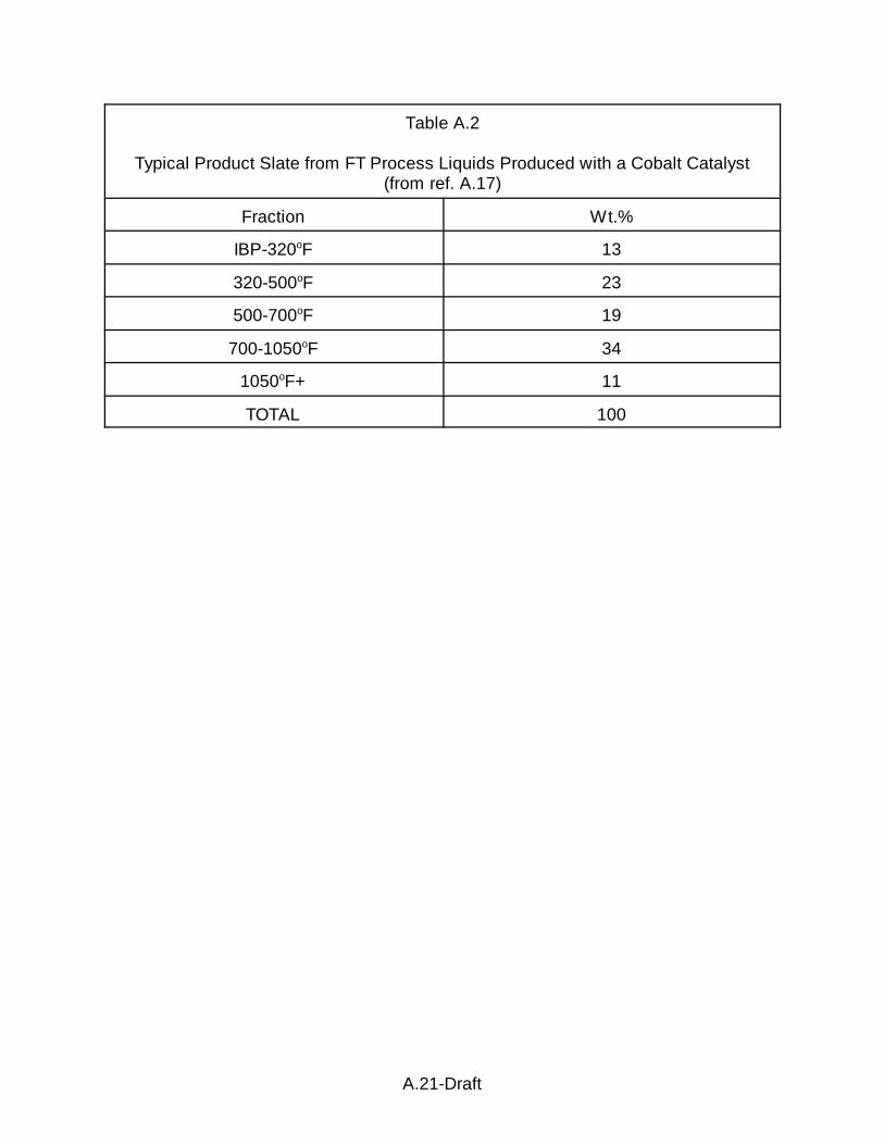
The authors indicate that a cobalt catalyst tends to produce heavier products,
e.g., containing C20+, whereas ruthenium tends to produce more distillate type
products, e.g., C5-C20. A typical product slate for a cobalt catalyst is given as (the
values may vary by ±10% for each fraction) is given in A.2.
Surprisingly, they found that hydrotreatment of the heavier fraction (containing
about 0.45 wt% oxygen) prevents the production of a product with the excellent cold
flow properties that was formed by hydroisomerization of the untreated material. They
indicate the need to limit the conversion for the 700oF+ to the 700oF- products to the
35-80% range as a measure to limit cracking to produce gases and thereby a lower
yield of distillates.
The lighter fraction can be the 320-500oF or, preferably, the entire liquid fraction
boiling below 500oF. Following a conventional hydrotreatment, the naphtha is flashed

A.16-Draft
off and the remaining material is hydroisomerized using a catalyst appropriate for light
fractions, such as the ones described in reference A.17.
The most active catalysts were those materials containing a surface silica
additive. However, it is stated that selectivity is more important than activity. Activity
was improved when a 4% surface SiO2/CoNiMo/10%SiO2-Al2O3 catalyst was used at
700 psig rather than 1,000 psig. Increasing the LHSV to 3.0 and increasing the
temperature to provide activity similar to that of LHSV = 0.5 to 1.0 dramatically effected
the products; the yield of jet fuel was decreased in favor of gas and naphtha production
and the jet fuel had an increased freeze point. The cause for this was not understood
but it was speculated that diffusional problems were the major factor.
An international patent application (A.18) claims the production of a high purity
solvent composition which comprises a mixture of paraffins of carbon number ranging
from about C8 to C20. The solvent has a molar ratio of iso-/n-paraffins ranging from
about 0.5:1 to 9:1 and the isoparaffins of the mixture contain greater than 50% of the
mono-methyl species. This patent application employees catalysts and processing
schemes that are included in reference (A.19).
The Fischer-Tropsch product was obtained from the conversion of a synthesis
gas (H2:CO = 2.11-2.16) with a titania supported cobalt-rhenium catalyst. The reaction
conditions were in the range of 422-428oF, 287-289 psig and feed linear velocity of 12
to 17.5. The alpha of the Fischer-Tropsch synthesis was 0.92.
The 700oF+ boiling fraction was hydroconverted over a Pd-silica-alumina
catalyst (0.5 wt.% Pd, 38 wt.% Al2O3) to produce 39.4 wt.% conversion of the 700oF+ to
700oF- materials ( A.3).

A.17-Draft
Wittenbrink et al. (A.20) describe a processing scheme whereby some
oxygenates (primary alcohols) remain in the finished fuel. These oxygenates function
to improve the lubricity of the diesel fuel.
The process scheme illustrated in their A.6 leads to some confusion.
Shown leaving the Fischer-Tropsch reactor (vessel 2) are two streams: 3 (700oF+;
370oC) and 4 (700oF-). It is reported that the reactor is operated in the range 422-
428oF (217-220oC) and 287-289 psig using a titania supported cobalt/rhenium catalyst
(A22). The syngas had a composition of H2/CO = 2.11-2.16. The alpha for FTS was
0.92. The FTS products were separated into three fractions having approximate boiling
ranges: (1) C5-500oF (designated F-T cold separator liquids); (2) 500-700oF (F.T. hot
separator liquids) and 700oF+ (F.T. reactor wax). It appears that streams 3 and 4 in
A.6 must be sent to a fractionator (not shown in the figure) to generate three
streams.
The hydroisomerization and recombining of fractions are the same, or
essentially the same, as described by Davis et al. (A.15) above.
References
A.1. Herskowitz, M.,, Method for hydrocarbon synthesis reactions; US patent
5,652,193, July 29, 1997.
A.2. D. C. Long, U. S. Patent 5,498,638, March 13, 1996.
A.3. D. C. Long, European Patent Office Publication No. 0 679 620 A2, April 26,
1995.
A.4. See, for example, U.S. 4,637,993; U.S. 4,717,702; U.S. 4,477,595; U.S. U.S.
4,663,305; U.S. 4,822,824; U.S. 5,036,032; U.S. 5,140,050; U.S. 5,292,705.
A.18-Draft
A.5. E. Herbolzheimer, F. J. Kaiser, Jr., and E. Iglesia; U. S. Patent 5,157,054,
October 20, 1992.
A.6. Clavenna, L. R., S. M. Davis, R. A. Fiato and G. R. Say; Stuucturally modified
alumina supports, and heat transfer solids for high temperature fluidized bed
reactions; U.S. 5,395,406, March 7, 1995.
A.7. Clavenna, L. R., S. M. Davis, G. R. Say and R. A. Fiato; Synthesis gas from
particulate catalysts, and admixutres of particulate catalysts and heat transfer
solids; U.S. 5,348,717, Sept. 20, 1994.
A.8. Davis, S. M., L. R. Clavenna, G. R. Say and R. A. Fiato; High surface purity heat
transfer solids for high temperature fluidized bed reactions; U.S. 5,360,778, Nov.
1, 1994.
A.9. Davis, S. M., L. R. Clavenna, G. R. Say and R. A. Fiato; High surface purity heat
transfer solids for high temperature fluidized bed reactions; U. S. Patent
5,496,531, March 5, 1996.
A.10. Clavenna, L. R., S. M. Davis, R. A. Fiato and G. R. Say; Particulate solids for
catalyst supports and heat transfer materials; U. S. Patent 5,395,813, March 7,
1995.
A.11. Davis, S. M., L. R. Clavenna, R. A. Fiato and G. R. Say; High performance
alumina heat transfer solids for high temperature fluidized bed synthesis gas
reactions; U.S. 5,360,777, Nov. 1, 1994.
A.12. Clavenns, L. R., R A Fiato and G. R. Say; Particulate solids for catalyst supports
and heat transfer materials, U.S. patent 5,476,877, Dec. 19, 1995.
A.13. T. M. Stark, U.S. Patent 5,409,960, April 25, 1995.
A.14. T. M. Stark, European patent application Number 94301541.2.

A.19-Draft
A.15. S. M. Davis, J. W. Johnson, C J. Mart, D. F. Ryan and R. J. Wittenbrink;
European Patent Application EP 0 753 563 A1, filed April 7, 1996.
A16. S. M. Davis and D. F. Ryan, U.S. Patent 5,378,348, January 3, 1995.
A.17. U.S. Patent 5,187,138]
A.18. WO 97/21787
A.19. U.S. Patent 5,378,348
A.20. R. J. Wittenbrink, R. F. Bauman, P. J. Berlowitz and B. R. Cook, International
Publication No. WO 97/14769, April 24, 1997.
A.21. U.S. Patent 4,568,663.
A.20-Draft
Table A.1
Reactor Simulation Results
Stage 2 Product
Stage 2 Feed Shifting Catalyst Non-shifting
Component Rates, Moles/Hr
H2 11584 3021 6781
CO 2823 564 524
CO2 16324 15065 16326
H2O 113 4887 2400
Hydrocarbon + Alcohol 13701 14045 13924
Inert 2434 2434 2434
Moles Converted
CO 2259 2299
CO2 1259 -2
Total 3518 2297
% (CO+CO2) Converted 18.4 12.0
Hydrocarbon + alcohol 344 223
Yield, Moles/Hr
A.21-Draft
Table A.2
Typical Product Slate from FT Process Liquids Produced with a Cobalt Catalyst(from ref. A.17)
Fraction Wt.%
IBP-320oF 13
320-500oF 23
500-700oF 19
700-1050oF 34
1050oF+ 11
TOTAL 100

A.22-Draft
Table A.3
Fischer-Tropsch Synthesis conditions
Operating Conditions
Temperature, oF 638
LHSV, v/v/h 1.2
Psig 711
H2 treat rate, SCF/B 2,100
Yields, Wt.%
C1-C4 0.97
C5-320oF 10.27
320-500oF 14.91
500-700oF 29.99
700oF+ 43.86
TOTAL 100
700oF Conversion, Wt.% 39.4
15/5 Distillation Yields, Wt.%
IBP-650oF 50.76
650oF+ 49.24

A.23-Draft
Figure A.1. Model predictions for methane selectivity as a function of pellet radiuscompared to experimental data (6% CO-0.5% Re catalyst; T = 200oC;
= 2.0; Pt = 19 atm) (from ref. A.????).(PH2/PCO)feed
Figure A.2. CO conversion and methane selectivity as a function of rim thickness forspherical particles (dp = 1.0 mm; T = 200oC; GHSV = 770 v/v/hr; --- A = .6x 10+5 mole/s/s•g•atm2; ))) A = 1.2 x 10+5 mole/mole/s/s•g•atm2) (from ref.A.1).

A.24-Draft
Figure A.3. CO conversion and methane selectivity as a function of rim thickness forring (---) and cylinder ( ))) ) pellets (dp = 1.0 mm; T = 200oC; GHSV = 770;A = 1.2 x 10⁵ mole/s•g•atm2 (from ref. A.1).
Figure A.4. Plot of decay length versus volume fraction solids concentration (#, 2cm/sec; G, 8 cm/sec; +, 4 cm/sec; X, 12 cm/sec; *, 6 cm/sec; ", 16-18cm/sec).

A.25-Draft
Figure A.5. A plot of volume fraction versus bed height when a second inert solid to afirst catalytically active solid in a bubble column, the inerts being of thesame density and diameter as the catalytic solid.
Figure A.6. Schematic of the process (from ref. A.21).