Embed Size (px)
Citation preview

FIRST WATT B4 USER MANUAL
By Nelson Pass
The B4 is a stereo active crossover filter system designed for high performance and flexibilityand is unique in several ways.
First, it uses only direct-coupled matched discrete complementary Jfets (the now unavailableToshiba 2SK170 and 2SJ74) in unity-gain buffer circuits without feedback. These buffersallow accurate interface between a very wide range of impedances in the filter components.They are adjusted for zero DC offset and do not require coupling capacitors. The filterresistors are high quality 1% Vishay commercial metal film types, and the filter capacitors areWima polypropylene film types.
Second, the B4 has a fantastic range and variety of filter values and characteristics. Each ofthe four filters offers 1, 2, 3 or 4 “poles” for each filter, corresponding to 6, 12, 18 or 24dB/octave slopes. Each of these filter poles is independently adjustable within each filter,allowing wide customization of the character of the filter. Each pole is adjustable from 25 to6275 Hz in 25 Hz increments, which is 255 settings per Pole, and the possible number ofsettings for the four poles of each filter is something like 400 million.
You might wonder why this variety would be necessary, and the answer is simple – theordinary “text book” set of filters cannot make allowance for the enormous range ofloudspeaker drivers, not to mention enclosures, environments and individual taste.Occasionally a standard filter will do a pretty good job, but you won't really know until youhave tried some of the alternatives. Usually there is a “best” setting, but it is not often amongthe settings found in “canned” active crossovers.
The B4 is intended to give the audiophile access to these possibilities with a minimum oftrouble. Inside are sets of clearly marked frequency switches for each of the four poles ofeach filter section weighted in binary increments - the frequency of that pole is simply thesum of the values of the switched which are turned ON.
If you want Sallen-Key values, they are clearly marked out. If you want filters whose highpass and low pass outputs still sum flat at 18 and 24 dB/octave, they are also either clearlymarked or prescribed by simple formula.
The B4 has an input impedance of 10 Kohms and output impedance of 125 ohms. Thebandwidth of the low pass is DC to the value of the filter frequency, and the bandwidth of thehigh pass is about -1 dB at 100 Khz.
The distortion of the all the circuitry in series is about .005% at 1 volt, and the maximumoutput is about 10V peak. The circuit will drive 600 ohm loads at slightly lower output andhigher distortion, but still does a good job. The noise in the unweighted audio band is a fewmicrovolts, or about -110 dBV, which is about -130 dB below peak output. The externalregulated switching supply is passively RC filtered to give very low noise.
On the following page is a slightly simplified overall schematic of the B4, showing onechannel of the stereo pair, followed by a discussion of the filter set:


There is a lot to the block diagram, but I will break it down for you. First, you will notice thatfor this one channel there are two sets of filters, the high pass filter (top) and the low passfilter (bottom). They have a common input, and an input switch on the left decides which filterwill have level attenuation. The other filter will see the direct input.
The high pass filter will be used to remove low frequencies from the input signal so as to feedan amplifier which is driving a high frequency loudspeaker driver, such as a tweeter. The lowpass filter removes the high frequencies and leaves a signal suitable for driving a woofer. Ifyou have a three-way system, much of the time you will be driving the midrange and tweetertogether with a “passive” crossover network and using this “active” crossover filter for thefiltering between woofer and midrange. Or maybe not.
The high pass filter and the low pass filter are identical in many respects, and you will findthat they are really different only in the interchange of resistor numbers 1 through 8 withcapacitors 1 through 8. Apart from the switching that you see in the diagram explicitly, thevalues of each resistor are made variable by the use of switches on the circuit board. As I amtrying to still keep this simple, you do not see these switches on this diagram, but we will getto them.
The high pass filter and the low pass filter are each independently buffered from the inputand the input attenuator. This assures that the attenuator and the impedance of the signalsource do not influence the performance of the filters. You see the buffers on the left – theyare the two complementary (N channel + P channel) Jfets operated as followers.
Proceeding to the right, the first two poles of the high pass and low pass filters are seen.Provision is made to select 6 or 12 dB/octave, and as noted earlier, the values of the resistorssetting the frequency character of these two poles can be independently set over a 255 to 1range. The signal is again buffered, and you will note that near the output of each filter is aswitch that can be used to bypass the filter entirely.
This output proceeds to the filters which provide the second two poles (3 and 4) for 18 or 24dB/octave slopes, and the same process is repeated. If you don't need 18 or 24 dB slopes,you can bypass the second filter set with the switch located near the output of the filter.Please note that if you are using 18 or 24 dB/octave slopes, you will not want to bypass theprevious filter as it provides the first 2 poles necessary for this character.
For the most part you can set things as you like, but there are some rules that will help keepyour head straight and ensure proper performance. As you add more poles to a filter set, dothem in numerical order. If you are making a 6 dB/octave filter, use pole 1. For 12 dB/octave,use poles 1 and 2. For 18 dB/octave, poles 1, 2 and 3. For 24 dB/octave, you will use poles1, 2, 3 and 4.
If you are not using a filter and have decided to bypass it, the last little bit of performance willbe obtained by placing all frequency values in that filter to the “off” position so that there iszero loading of the previous stage.
By the way, the circuit is designed not to make noises as you flip switches or change jumpers,but it is probably smart to turn the amplifiers off anyway.
Here is what you will see on the circuit board representing one channel:

We are going to use this diagram to discuss how you use the switches and jumpers to get thefrequencies and characteristics you want. You can see that the filter sections of the B4 havebeen blocked off and labeled to keep things as clear as possible. Anything having to do withthe settings of a filter section are contained within the boundaries shown on the printed circuitboard.
There are eight of these filter sections, four for each channel. Of these four, two are for theLow Pass filter system, and two for the High Pass filter system.
First off, in each section you can see the three pin BYPASS jumper located in the upper lefthand corner. To bypass an unused filter set, place the jumper on the two pins labeled OUT.To put the filter in the circuit place the jumper on the IN side.
For the first two poles of the High Pass and Low Pass filters you will see jumper pins labeledSLOPE 6/12, and you will set the jumper on 6 for a 6 dB/octave slope, and 12 for a 12dB/octave slope. (If you are setting the filter system for 18 or 24 dB/octave, you will be usingthis filter in the 12 setting).
For poles 3 and 4, you will be setting the corresponding SLOPE jumpers on the second set offilters at 18 or 24.
There is another set of jumpers on the Low Pass filters labeled S and L. Ordinarily these willbe set at S which stands for “Sallen Key” which is a standard filter type. The L setting isprovided to switch a capacitor on each filter so as to implement a “Linkwitz-Riley” value setwhen you are using 24 dB/octave setting (more on that later).
Each of the four filter poles for the high and low pass filters has an 8 position DIP switch toset the value of the resistors in the filter. The frequency of each pole of the filter is variablefrom 25 Hz to 6375 Hz in 25 Hz steps, and the switches are labeled 25, 50, 100, 200, 400,800, 1600 and 3200 Hz. You activate a frequency value for the pole by pushing the switch tothe ON position, which is on the side with the frequency label.
These values are weighted in binary, and the frequency of the Pole is the sum of thefrequencies of all the switches that are ON. For example, activating 50 and 200 gives afrequency of 250 Hz. Pushing them all on gives 6375 Hz. This is true for the S settings,which you will see clearly labeled next to the switch.
With the optional L setting, you will see another table which applies, and it is printed on thecircuit board to the right of the S table. Here the range is in 34 Hz steps up to 4366 Hz.
In ordinary active crossovers, you will generally see that if the values of the filter areadjustable, they are ganged in groups so that all the poles are set at the same frequency. Inthe B4 they are all independently adjustable and can be set any which way.
This is important because usually the characteristics of a loudspeaker driver (and the driver itis crossing to) are such that you have to vary the values of each of the possible frequencypoles independently to get the optimal performance. The chance that a “textbook” filter valuewill be the best is pretty unlikely.
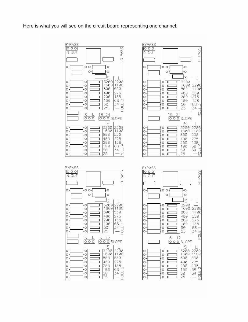
Let's look at some of the curves these filters can generate:
Above you see most of the 255 values you will get with a 6 dB/octave low pass filter (I did notreally do them all because I am lazy). In the sets of curves that follow, we will see only thelines corresponding to single switch settings, remembering that there are 247 more for eachpole. Also note that these graphs all assume the S setting unless otherwise noted, and theyall have the poles at equal values. It would not be possible for me to show you all thepossible variations.
Here are the Low Pass response curves:
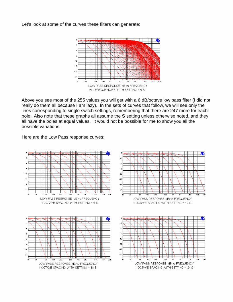
Here are the High Pass response curves:
At this point, I hope you are getting the idea.
In spite of the fact that you can set these filters up with a huge combination of possibilities, itis still useful to consider some standard configurations as a starting point. Ideally, we wantthe output of low frequency and high frequency loudspeaker drivers to come togethersmoothly at the frequency crossover point. We want to have the acoustic output sum flat andwith a minimum of phase distortion.
The perfect loudspeaker driver would not need a crossover in any case, but we will let thatgo, observing that the more perfect the driver, the less need there is for more filter poles.
Routinely, high slope filters are used to compensate for the physical frailty of tweeters whenexposed to low frequencies or woofers which have spurious peaks at higher frequencies. Fornearly perfect drivers we can consider single pole solutions at 6 dB/octave because we don'thave to worry about breaking the tweeter or enjoying high frequency cone resonances of thewoofer.
Your average loudspeaker driver also has a limited bandwidth – it rolls off at low frequenciesand also at high frequencies. These roll-offs add their own poles to the overall result withaccompanying response and phase deviations. Nevertheless, we will start with theassumption of perfect loudspeaker drivers, looking at the filter sets which would deliver a flatsummed amplitude response.
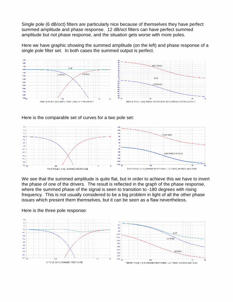
Single pole (6 dB/oct) filters are particularly nice because of themselves they have perfectsummed amplitude and phase response. 12 dB/oct filters can have perfect summedamplitude but not phase response, and the situation gets worse with more poles.
Here we have graphic showing the summed amplitude (on the left) and phase response of asingle pole filter set. In both cases the summed output is perfect.
Here is the comparable set of curves for a two pole set:
We see that the summed amplitude is quite flat, but in order to achieve this we have to invertthe phase of one of the drivers. The result is reflected in the graph of the phase response,where the summed phase of the signal is seen to transition to -180 degrees with risingfrequency. This is not usually considered to be a big problem in light of all the other phaseissues which present them themselves, but it can be seen as a flaw nevertheless.
Here is the three pole response:
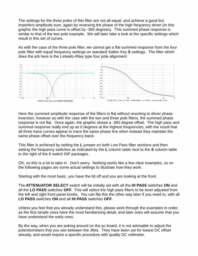
The settings for the three poles of this filter are not all equal, and achieve a good butimperfect amplitude sum, again by reversing the phase of the high frequency driver (In thisgraphic the high pass curve is offset by -360 degrees). This summed phase response issimilar to that of the two pole example. We will later take a look at the specific settings whichresult in this set of curves.
As with the case of the three pole filter, we cannot get a flat summed response from the fourpole filter with equal frequency settings on standard Sallen Key S settings. The filter whichdoes the job here is the Linkwitz-Riley type four pole alignment:
Here the summed amplitude response of the filters is flat without resorting to driver phaseinversion, however as with the case with the two and three pole filters, the summed phaseresponse is not flat. Once again, the graphic shows a -360 degree offset. The high pass andsummed response really end up as 0 degrees at the highest frequencies, with the result thatall three trace curves appear to trace the same phase line when instead they maintain thesame phase offset over the frequency band.
This filter is achieved by setting the L jumper on both Low Pass filter sections and thensetting the frequency switches as indicated by the L column table next to the S column tableto the right of the 8 switch DIP packages..
OK, so this is a lot to take in. Don't worry. Nothing works like a few clear examples, so onthe following pages are some actual settings to illustrate how they work.
Starting with the most basic, you have the lid off and you are looking at the front.
The ATTENUATOR SELECT switch will be initially set with all the HI PASS switches ON andall the LO PASS switches OFF. This will select the high pass filters to be level adjusted fromthe left and right front panel knobs. You can flip this the other way later if you need to, with allLO PASS switches ON and all HI PASS switches OFF.
Unless you feel that you already understand this, please work through the examples in order,as the first simple ones have the most familiarizing detail, and later ones will assume that youhave understood the early ones.
By the way, when you are poking around on the pc board, it is not advisable to adjust thepotentiometers that you see between the Jfets. They have been set for lowest DC offsetalready, and would require a specific procedure with quality DC voltmeter.

Example 1 - Simple 6 dB/oct crossover at 1000 Hz.
Setting the jumpers:
Go to the the first LEFT LO PASS section located on the lower left
Set the jumper labeled S L to S (this enables the Sallen Key filter alignment)
Set the jumper labeled SLOPE to 6 (this sets the slope to 6 dB/octave)
Set the jumper labeled BYPASS to IN (this puts this filter in the circuit)
Now go up to the second LEFT LO PASS section
Set the jumper labeled S L to S (it doesn't really matter, since this filter is unused)
Set the jumper labeled SLOPE to 18 (also doesn't really matter)
Set the jumper labeled BYPASS to OUT (this bypasses the second filter set)
Now go to the RIGHT LO PASS filters and set them the same way
Go to the closest LEFT HI PASS filter and set the SLOPE TO 6
Set the BYPASS to IN
Go to the second LEFT HI PASS filter and set the SLOPE to 6
Set the BYPASS to OUT
Now do the same for the RIGHT HI PASS filters
Setting the filter frequencies:
I suggest you first go to each of the 16 banks of switches in the filter system and push theswitches to the OFF position, which is on the left, away from the number labels.
Since this is only a single pole filter we are making, we will be using only the switch banksidentified as POLE 1, which you can see marked to the right of each bank. On the fourbanks labeled POLE 1, set the switches marked 800 and 200 in the S column to the ONposition. This sets the frequency to 800 + 200 = 1000 Hz, which is what we set out to do.Leave all the other filter switches in the OFF position, as they are unused.
You are done. Put the lid on, connect the B4 to your system, plug the power supply into thewall, turn on the amplifiers and see what you've got.
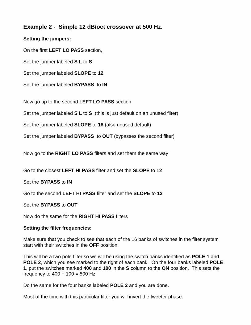
Example 2 - Simple 12 dB/oct crossover at 500 Hz.
Setting the jumpers:
On the first LEFT LO PASS section,
Set the jumper labeled S L to S
Set the jumper labeled SLOPE to 12
Set the jumper labeled BYPASS to IN
Now go up to the second LEFT LO PASS section
Set the jumper labeled S L to S (this is just default on an unused filter)
Set the jumper labeled SLOPE to 18 (also unused default)
Set the jumper labeled BYPASS to OUT (bypasses the second filter)
Now go to the RIGHT LO PASS filters and set them the same way
Go to the closest LEFT HI PASS filter and set the SLOPE to 12
Set the BYPASS to IN
Go to the second LEFT HI PASS filter and set the SLOPE to 12
Set the BYPASS to OUT
Now do the same for the RIGHT HI PASS filters
Setting the filter frequencies:
Make sure that you check to see that each of the 16 banks of switches in the filter systemstart with their switches in the OFF position.
This will be a two pole filter so we will be using the switch banks identified as POLE 1 andPOLE 2, which you see marked to the right of each bank. On the four banks labeled POLE1, put the switches marked 400 and 100 in the S column to the ON position. This sets thefrequency to 400 + 100 = 500 Hz.
Do the same for the four banks labeled POLE 2 and you are done.
Most of the time with this particular filter you will invert the tweeter phase.

Example 3 - 6 dB/oct 500 Hz Low Pass and 12 dB/oct 800 Hz High Pass
Setting the jumpers:
On the first LEFT LO PASS section,
Set the jumper labeled S L to S
Set the jumper labeled SLOPE to 6
Set the jumper labeled BYPASS to IN
Now go up to the second LEFT LO PASS section
Set the jumper labeled S L to S (unused default)
Set the jumper labeled SLOPE to 18 (unused default)
Set the jumper labeled BYPASS to OUT (bypasses the second filter)
Now go to the RIGHT LO PASS filters and set them the same way
Go to the closest LEFT HI PASS filter and set the SLOPE to 12
Set the BYPASS to IN
Go to the second LEFT HI PASS filter and set the SLOPE to 12
Set the BYPASS to OUT
Now do the same for the RIGHT HI PASS filters
Setting the filter frequencies:
Initially check that all the switches of the 16 banks in the filter system start in the OFFposition.
POLE 1 switch banks for the LO PASS filters will be set at 400 and 100 (S column) for a 500Hz filter frequency.
For the High Pass filters both POLE 1 and POLE 2 switches will be set at 800.

Example 4 - 18 dB/oct 800 Hz Low Pass and 18 dB/oct 800 Hz High Pass
Setting the jumpers:
On the first LEFT LO PASS section,
Set the jumper labeled S L to S
Set the jumper labeled SLOPE to 12
Set the jumper labeled BYPASS to IN
Now go up to the second LEFT LO PASS section
Set the jumper labeled S L to S
Set the jumper labeled SLOPE to 18
Set the jumper labeled BYPASS to IN
Go to the RIGHT LO PASS filters and set them the same way
Now go to the closest LEFT HI PASS filter and set the SLOPE to 12
Set the BYPASS to IN
Go to the second LEFT HI PASS filter and set the SLOPE to 18
Set the BYPASS to IN
Now do the same for the RIGHT HI PASS filters
Setting the filter frequencies:
The example includes information on creating the three pole filters which sum flat asdescribed before. Because the frequencies of the various poles will be at different values,some math is required. The desired frequency F is 800. Keep in mind that this is just anexample of the how you might use the flexibility of these filters to get what you want.
The Low Pass filters will use POLE 1 = 2F, POLE 2 = 2F and POLE 3 = F, so POLE 1 will beset at 1600 Hz, POLE 2 is at 1600 Hz, and POLE 3 is 800 Hz (S column labels).
The High Pass filters will use POLE 1 = F, POLE 2 = F/2 and POLE 3 = F/2, so we will setPOLE 1 at 800 Hz, POLE 2 at 400 Hz, and POLE 3 at 400 Hz (using the S column labels).
Here you will often want to invert the phase of the tweeter. Of course nothing prevents youfrom running poles at the same frequencies or other frequencies – this is just an example ofsomething that might be really good if you had perfect loudspeaker drivers, which you don't.

Example 5 - 24 dB/oct 800 Hz Linkwitz-Riley
Setting the jumpers:
On the first LEFT LO PASS section,
Set the jumper labeled S L to L
Set the jumper labeled SLOPE to 12
Set the jumper labeled BYPASS to IN
Now go up to the second LEFT LO PASS section
Set the jumper labeled S L to L
Set the jumper labeled SLOPE to 24
Set the jumper labeled BYPASS to IN
Now go to the RIGHT LO PASS filters and set them the same way
Go to the closest LEFT HI PASS filter and set the SLOPE to 12
Set the BYPASS to IN
Go to the second LEFT HI PASS filter and set the SLOPE to 24
Set the BYPASS to IN
Now do the same for the RIGHT HI PASS filters
Setting the filter frequencies:
The example is the popular Linkwitz-Riley four pole filters which sum flat with the driverswired in phase as described before. Once again, different pole frequencies are required, butfor your convenience they have been tabulated in the L columns on the pc board switches.
This filter goes in 34 Hz increments to 4366 Hz, and you will select the same frequency for allfour poles of both the Low Pass and High Pass filter sections. If we select frequencies 550 +138 + 68 + 34 = 791 Hz, then this will be as close as we can get to 800 Hz, and so that iswhat we will do.
Once again, nothing prevents you from using the S column settings and selecting whateverfrequencies you want for whatever filter poles. It is likely that you will have to do so in the endanyway, as the assumption of perfect drivers is still present. You can see lots more abouthow Siegfried Linkwitz has dealt effectively with these issues at www.linkwitzlabs.com.
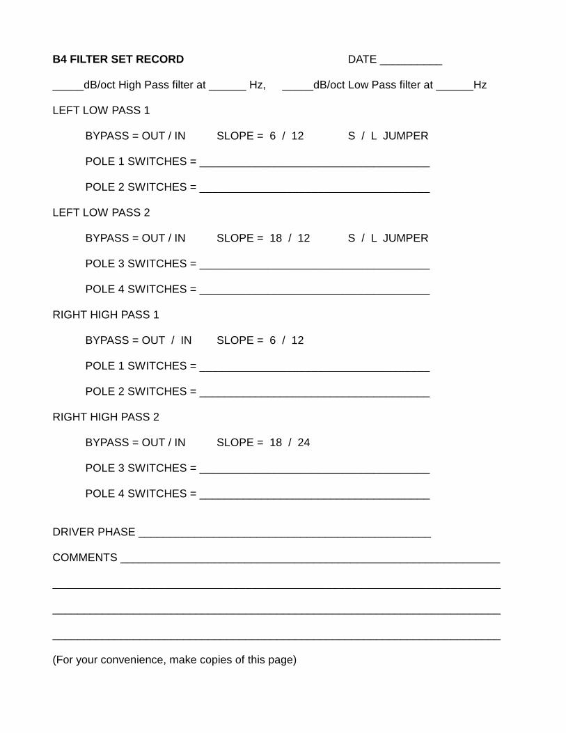
B4 FILTER SET RECORD DATE __________
_____dB/oct High Pass filter at ______ Hz, _____dB/oct Low Pass filter at ______Hz
LEFT LOW PASS 1
BYPASS = OUT / IN SLOPE = 6 / 12 S / L JUMPER
POLE 1 SWITCHES = _____________________________________
POLE 2 SWITCHES = _____________________________________
LEFT LOW PASS 2
BYPASS = OUT / IN SLOPE = 18 / 12 S / L JUMPER
POLE 3 SWITCHES = _____________________________________
POLE 4 SWITCHES = _____________________________________
RIGHT HIGH PASS 1
BYPASS = OUT / IN SLOPE = 6 / 12
POLE 1 SWITCHES = _____________________________________
POLE 2 SWITCHES = _____________________________________
RIGHT HIGH PASS 2
BYPASS = OUT / IN SLOPE = 18 / 24
POLE 3 SWITCHES = _____________________________________
POLE 4 SWITCHES = _____________________________________
DRIVER PHASE _______________________________________________
COMMENTS _____________________________________________________________
________________________________________________________________________
________________________________________________________________________
________________________________________________________________________ (For your convenience, make copies of this page)

TRI-AMPING
Many systems have crossovers that divide the frequencies more than once for more than twodrivers. Systems with three drivers can make use of tri-amping with three channels ofamplifier and an additional crossover network.
To do this, you will take another B4 or similar crossover and feed one of the outputs, eitherhigh or low pass into the input of the second crossover. It is arbitrary which you use. Onecrossover is set up for one of the crossover points, and the other crossover is set up for theother. The result is three output, generally a Low Pass, a Band Pass, and a High Pass.However you do it, the Band Pass will certainly be coming out of the second crossover box.
In this picture you can see an example of phase inversion, where the midrange is reversed.
You can keep adding crossovers to filter for an arbitrary number of drivers. You will be addinga box for each additional driver. It is also possible to get even higher slopes. You can placetwo B4 channels in series to get 48 dB/octave for example.
Helpful Hints
Finding the best settings for the crossover on a given system usually requires time andpatience. If you know what you like when you hear it, then you could simply go through allpermutations of the frequency and slope settings (and flipping the phase of drivers). Thereare many possibilities with the B4, so it's probably wise to find a likely place to start. Most ofthe time you will have some idea of where to start, but it should be emphasized thatexperimentation with values and listening over time are nearly always necessary to extractthe best possible performance.

If you want good results with the least amount of effort, it is very helpful to have a microphoneand some electronics to make some measurements. To be useful, the microphone doesn'thave to be particularly good or expensive – there are some decent little electret microphonesand inexpensive pre-amplifiers available from places like Madisound or Parts Express for ahundred dollars or less, and you can use your computer sound card and free software.
High accuracy is not required. For the most part you need to be able to comparativelyexamine the differences between different settings around the crossover region as asupplement to listening. Your ears will still tell you what sounds good and not, but thingsusually go a lot quicker if you can see some graphics.
Most ideally the response will be pretty flat with both drivers wired in-phase. If not, try flippingthe phase of a driver, usually the higher frequency one. If that doesn't flatten it out, then youcan start fooling with different crossover frequencies and slopes until it is reasonably flat.
You then might think you're done, but maybe not. It's possible for the response to be flat andstill have flawed sound because the drivers are not truly agreeing with each other on phase,and this can make for a big difference in the sound.
Having done this a bit, I have a simple procedure that usually gets me close to where I wantto be fairly quickly. I put the drivers in phase and I fool around with the filter values until I getthe flattest response I can in the crossover region. Then I measure the low frequency driveralone (with the other off) and then the high frequency driver alone. If you overlay the threeplots of the two drivers alone along with the summed response, then you are looking for thefollowing characteristics – the drivers should meet at the crossover point in such a way thateach is about -6 dB from the value of the flat summed response.
Alternatively, Siegfried Linkwitz points out that you can seek the deepest notch to be hadwhen the drivers are incorrectly phased and then reverse the phase to hopefully get theflattest response which also probably has the best phase character.
This simple approach usually speeds up the process of getting the system to sound its best -and is a good starting point. Don't rely too much on simply flat response when adjustingcrossover networks, and be prepared to use your ears over an extended amount of time toget it just right. Experimentation is very important here, and it include loudspeaker positioningand all the other things you can alter as a test.
Your results will vary, but the important thing is to have patience and perseverance. Try toenjoy the process of refining your loudspeaker's sound, and allow for the time and effort itusually takes.
Always remember that this is supposed to be fun.
Copyright 2014 First Watt
www.firstwatt.com