Embed Size (px)
Citation preview

UCRL-JRNL-212668
First study of nano-compositescintillators under alphairradiation
S. Letant, T.-F. Wang
June 2, 2005
Applied Physics Letters

Disclaimer
This document was prepared as an account of work sponsored by an agency of the United States Government. Neither the United States Government nor the University of California nor any of their employees, makes any warranty, express or implied, or assumes any legal liability or responsibility for the accuracy, completeness, or usefulness of any information, apparatus, product, or process disclosed, or represents that its use would not infringe privately owned rights. Reference herein to any specific commercial product, process, or service by trade name, trademark, manufacturer, or otherwise, does not necessarily constitute or imply its endorsement, recommendation, or favoring by the United States Government or the University of California. The views and opinions of authors expressed herein do not necessarily state or reflect those of the United States Government or the University of California, and shall not be used for advertising or product endorsement purposes.

S. E. Létant et al.
APL 1
First study of nano-composite scintillators under alpha irradiation
S. E. Létant and T.-F. Wanga)
Chemistry and Materials Science Directorate, Lawrence Livermore National Laboratory, 7000 East Avenue, Livermore, California, 94550
We demonstrate that nano-composite materials based on semiconductor quantum dots
have great potential for radiation detection via scintillation. While quantum dots and laser
dyes both emit in the visible range at room temperature, the Stokes shift of the dyes is
significantly larger. The scintillation output of both systems was studied under alpha
irradiation and interpreted using a combination of energy-loss and photon transport
Monte Carlo simulation models. The comparison of the two systems, which allows the
quantification of the role played by the Stokes shift in the scintillation output, opens up
exciting possibilities for a new class of scintillators that would take advantage of the
limitless assembly of nano-crystals in large, transparent, and sturdy matrices.
a)Author to whom correspondence should be addressed; electronic mail: [email protected]

S. E. Létant et al.
APL 2
Although both the synthesis and characterization of quantum dots have been developed
for more than a decade,1,2 the applications explored to date seem to have focused on
tagging,3 chemical and biological sensing,4 and lasing applications.5 The interest
generated by quantum dots in both academic and industrial research communities comes
from the fact that the optical properties of these materials are directly tied to their
composition, size, and geometry, therefore allowing the engineering of key parameters
such as emission wavelength and quantum efficiency.
Standard gamma-ray detection technology relies on cooled germanium detectors (0.2 %
energy resolution at 1.33 MeV)6-8 and on scintillating crystals such as sodium iodide (7 %
energy resolution at 662 keV).9 The main problem associated with the former is the
necessity to cool and stabilize the detector at a temperature near liquid nitrogen to reduce
thermal noise. The main problem associated with the latter is its poor energy resolution
and the limited choice of photon transducers (photomultipliers).
The use of nano-composite materials could potentially lead to a new class of scintillators
that would operate at room temperature, and more importantly, that would not rely on
crystal growth, but on the assembly of nanometer-sized crystals in a transparent and
sturdy matrix. Moreover, scintillator materials have output wavelengths in the UV and
blue (the most commonly used scintillator, sodium iodide, emits at 460 nm), wavelengths
at which the quantum efficiency of photomultiplier tubes (PMT) is below 25 %.10 This
means that, even in an ideal situation, only ¼ of the photons produced in the scintillator
material are detected. The use of quantum dots as a scintillator medium would allow fine
tuning of the output wavelength in the visible range and therefore, the use of avalanche

S. E. Létant et al.
APL 3
photodiodes (APD) with quantum efficiencies up to 70%.11 The visible band gap of
quantum dots would ensure both high photon output and efficient photon counting.
To the best of our knowledge, only one preliminary example of nano-crystal-based
scintillator has been reported to date.12 In this work, core/shell (CdSe)ZnS quantum dots
were embedded into a thin lithiated sol-gel matrix, characterized optically, and tested
with an alpha source. Unfortunately, no conclusion can be drawn from this publication
since the only scintillation spectrum presented was not corrected from the background
radiation. In this letter, we demonstrate the ability of quantum dots to convert alpha
radiation into visible photons, compare the scintillation output of quantum dots and laser
dye molecules, and interpret the results using a combination of energy-loss and photon
transport models. This set of data allows us to discuss the limitations of basic quantum
dots for gamma-radiation application that require large volumes of scintillator material,
and to suggest a new route to solve these issues.
Porous VYCOR® was purchased from Advanced Glass and Ceramics (Holden, MA) in
1/16 inch thick sheets. As received, the material is constituted of an array of
interconnected pores with a diameter of 4 nm and is opalescent. The porous glass matrix
was slowly dissolved for 4 days in an aqueous solution containing 1 % of hydrofluoric
acid and 20 % of ethanol per volume, rinsed in ethanol, and dried in air. The purpose of
this step was to slightly enhance the pore size and to obtain a clear matrix. SEM top
views of the material recorded after etching, cleaning, and drying without applying any
conductive coating on the sample surface (see Fig.1(a)) revealed an average pore
diameter in the 10-20 nm range. The absorption curve of the same material shows very
good transparency in the visible range (see Fig.1(b)). Porous glass constitutes a matrix of

S. E. Létant et al.
APL 4
choice for scintillation applications because it is made of a succession of nanometer-sized
cavities that can hold guest molecules while separating them from each other, therefore
preventing self-quenching effects. In addition, it is sturdy, inert, and transparent.
CdSe/ZnS core shell quantum dots with a luminescence output at 540 nm were purchased
from Evident Technologies (Troy, NY) and suspended in toluene at a concentration of 10
mg / mL. Rhodamine B laser dye was purchased from Sigma-Aldrich (Milwaukee, WI)
and suspended in methanol at a concentration of 0.5 mM. The dry ‘thirsty’ porous glass
pieces were immersed in the solutions of dots or dyes for 48 H with continuous stirring in
order to allow homogeneous diffusion of the guest molecules into the nano-porous host
matrix. They were then let to dry in order to evaporate the solvent.
Absorbance spectra of the samples were recorded using a UV-vis spectrometer (Cary
100, Varian Inc.) and emission spectra were recorded using a fluorimeter fitted with an
optic fiber (Cary Eclipse, Varian Inc.). The spectra as well as pictures of the devices are
presented in Fig.2. Although both quantum dots and laser dyes present similarities such
as their tunable absorption and emission spectra in the visible range, one noticeable
difference is that laser dye molecules have an inherent Stokes shift (shift between
absorption and emission wavelength) due to vibrational energy levels while quantum dots
do not.
An alpha source ( 243-244 Cm, 0.2 µC) was placed in contact with one side of the 1/16 inch
thick porous glass sample and a PMT (model R1924A from Hamamatsu) probing a 1.5
cm diameter area rested directly on the other side to count visible photons coming out of
the material. Photons coming out of the nano-composite material samples under alpha
irradiation were integrated for 10 H with an amplifier and a multi-channel analyzer.

S. E. Létant et al.
APL 5
Figure 3 shows the scintillation output recorded with the 243-244 Cm source, through the
dot and dye samples. The data presented on Fig.3 shows that the quantum dot system
does convert the alpha radiation into visible photons, but that the scintillation output of
the laser dye system is significantly higher, showing partial energy resolution of the 243-
244 Cm source.
In order to specifically understand the role played by the Stokes shift on the energy
resolution for both dye and dot systems, as well as to account for the wavelength
mismatch between the emission of the sample and the optimal detection of the PMT, we
performed simulations using a combination of TRIM and DETECT 2000 programs in
history mode.13,14 Photons generated at the source/sample interface traveled to the PMT
surface which was located on the opposite side of the sample. The history was analyzed
and the energy deposition and light transport were simulated while accounting for
properties of the scintillator media such as the wavelength-dependent absorption and
emission coefficients of the emitters (dot or dye), the nature of the matrix (reflectivity,
index of refraction, scattering length, absorption length), and the scintillation decay
times.
The wavelength-dependent quantum efficiency of the PMT provided by the Hamamatsu
specification sheet was entered into the simulation code. We found that in our un-
optimized experimental conditions, about 4.1 % of the photons generated in the dye
system were amplified by the PMT, and that 0.4 % were amplified for the dot system.
Replacing the PMT, which only has a quantum efficiency of 4 % in the green, by an
APD, which has a maximum quantum efficiency of 70 %, would lead to an improvement
S. E. Létant et al.
APL 6
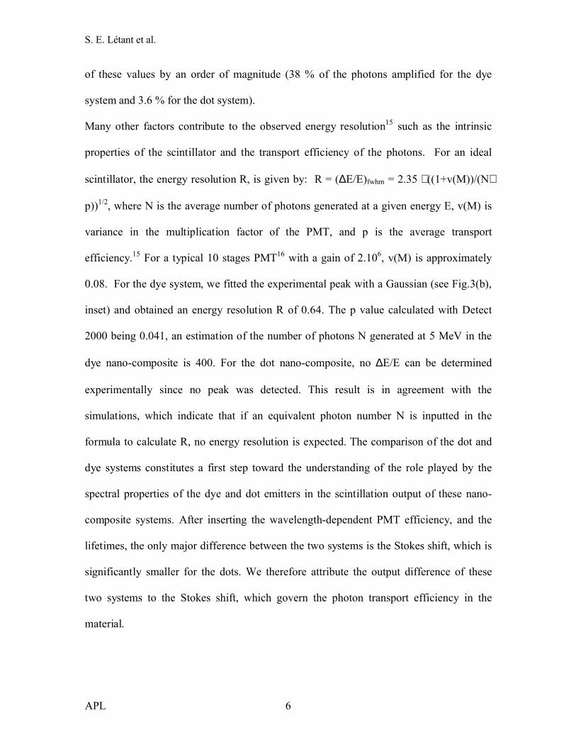
of these values by an order of magnitude (38 % of the photons amplified for the dye
system and 3.6 % for the dot system).
Many other factors contribute to the observed energy resolution15 such as the intrinsic
properties of the scintillator and the transport efficiency of the photons. For an ideal
scintillator, the energy resolution R, is given by: R = (∆E/E)fwhm = 2.35 ⋅ ((1+v(M))/(N⋅
p))1/2, where N is the average number of photons generated at a given energy E, v(M) is
variance in the multiplication factor of the PMT, and p is the average transport
efficiency.15 For a typical 10 stages PMT16 with a gain of 2.106, v(M) is approximately
0.08. For the dye system, we fitted the experimental peak with a Gaussian (see Fig.3(b),
inset) and obtained an energy resolution R of 0.64. The p value calculated with Detect
2000 being 0.041, an estimation of the number of photons N generated at 5 MeV in the
dye nano-composite is 400. For the dot nano-composite, no ∆E/E can be determined
experimentally since no peak was detected. This result is in agreement with the
simulations, which indicate that if an equivalent photon number N is inputted in the
formula to calculate R, no energy resolution is expected. The comparison of the dot and
dye systems constitutes a first step toward the understanding of the role played by the
spectral properties of the dye and dot emitters in the scintillation output of these nano-
composite systems. After inserting the wavelength-dependent PMT efficiency, and the
lifetimes, the only major difference between the two systems is the Stokes shift, which is
significantly smaller for the dots. We therefore attribute the output difference of these
two systems to the Stokes shift, which govern the photon transport efficiency in the
material.

S. E. Létant et al.
APL 7
Although the number of photons generated at 5 MeV in the present nano-composite
systems is low (a commonly used scintillator material such as NaI produces about 30,000
photons at 1MeV), this number can change dramatically for thicker samples studied with
penetrable gamma-rays. Moreover, the present systems have neither been optimized for
loss minimization (reflective coating on all surfaces) nor for detection efficiency (APD
instead of PMT).
Ultimately, simulations show that an energy resolution of about 2 % can be expected for
these new quantum dot nano-composite materials due to their visible band gap. This
approach would provide gamma-ray detectors with an energy resolution between the
cooled semiconductor detectors and the inorganic scintillator crystals without any
limitation on the area and volume of the detector and with room temperature operation.
Our experimental results, coupled with simulations, demonstrated that in order to achieve
this goal, the next step is to engineer the Stokes shift of semiconductor quantum dots. We
will do this by using different materials such as PbS, or by anchoring organic chemical
groups at the surface of the quantum dots.17
This work was performed under the auspices of the U.S. Department of Energy by
University of California Lawrence Livermore National Laboratory under contract No. W-
7405-Eng-48. It was supported by a Laboratory Directed Research and Development
grant (grant # 04-ERD-107).

S. E. Létant et al.
APL 8
REFERENCES
1 C. B. Murray, D. J. Norris, and M. G. Bawendi, J. Am. Chem. Soc. 115, 8706-8715 (1993).
2 X. Peng, M. C. Schlamp, A. V. Kadavanich, and A. P. Alivisatos, J. Am. Chem. Soc. 119, 7019-7029 (1997).
3 S. Kim, Y. T. Lim, E. G. Soltesz, A. M. De Grand, J. Lee, A. Nakayama, J. A. Parker, T. Mihaljevic, R. G. Laurence, D. M. Dor, L. H. Cohn, M. G. Bawendi, and J. V. Frangioni, Nature Biotech. 22, 93-97 (2004).
4 I. L. Medintz, A. R. Clapp, H. Mattoussi, E. R. Goldman, B. Fisher, and J. M. Mauro, Nature Materials 2, 630-638 (2003).
5 Y. Chan, J. S. Steckel, P. T. Snee, J.-M. Caruge, J. M. Hodgkiss, D. G. Nocera, and M. G. Bawendi, Appl. Phys Lett. 86, 73102 (2005).
6 D. E. Persyk, M. A. Schardt, T. E. Moi, K. A. Ritter, and G. Muehllehner, IEEE Trans. Nucl. Sci. 27, 168-171 (1980).
7 L. A. Andryushchenko, B. V. Grinev, A. M. Litichevskii, and L. V. Udovichenko, Instruments and Experimental Techniques 40, 59-63 (1997).
8 M. Moszynski, M. Balcerzyk, W. Czarnacki, M. Kapusta, W. Klamra, P. Schotanus, A. Syntfeld, and M. Szawlowski, IEEE Trans. Nucl. Sci. 50, 767-773 (2003).
9 W. H. Berninge, IEEE Trans. Nucl. Sci. 21, 374-378 (1974).10 M. Itaya, T. Inagaki, T. Iwata, G. I. Lim, H. Oishi, H. Okuno, Y. Tajima, H. Y.
Yoshida, and Y. Yoshimura, Nuclear Instruments & Methods in Physics Research A 522, 477-486 (2004).
11 M. Akiba, M. Fujiwara, and M. Sasaki, Optics Letters 30, 123-125 (2005).12 S. Dai, S. Saengkerdsub, H.-J. Im, A. C. Stephan, and S. M. Mahurin, AIP
Conference Proceedings 632, 220-224 (2002).13 J. F. Ziegler, J. P. Biersack, and U. Littmark, The stopping and range of ions in
solids, Pergamon press, New York (1985).14 G. F. Knoll, T. F. Knoll, and T. M. Henderson, IEEE Trans. Nucl. Sci. 35, 872-
875 (1988).15 J. B. Birks, The theory and practice of scintillation counting, Pergamon Press,
New York (1967).16 P. Dorenbos, J. T. M. de Haas, and C. W. E. van Eijk, IEEE Trans. Nucl. Sci. 42,
2190-2202 (1995).17 A. Puzder, A. J. Williamson, J. C. Grossman, and G. Galli, J. Am. Chem. Soc.
125, 2786-2791 (2003).

S. E. Létant et al.
APL 9
FIGURE CAPTIONS
FIG. 1. Characterization of the etched, cleaned, and dried porous glass matrix: a) SEM
top views, without any conductive coating. b) Absorbance spectrum of a 1/16 inch thick
slab.
FIG. 2. Absorbance and emission spectra of (a) porous glass impregnated with quantum
dots, and (b) porous glass impregnated with Rhodamine B laser dye. Pictures of the
devices are presented in inset.
FIG. 3. Background-subtracted scintillation output upon exposure to a 243-244Cm source,
recorded for 10 H, for (a) porous glass impregnated with quantum dots, and (b) porous
glass impregnated with Rhodamine B dye. The peak recorded for the dye sample was
fitted with a Gaussian curve (black line). The spectrum of the alpha source was measured
using a Si(SB) detector and is presented in inset.

S. E. Létant et al.
APL 10
Figure 1
10
8
6
4
2
0
Abs
orba
nce
800700600500400300200Wavelength (nm)
UV VISIBLE IR
Porous glass matrix
(a)
(b)

S. E. Létant et al.
APL 11
Figure 2
1.0
0.8
0.6
0.4
0.2
0.0
Abs
orba
nce
650600550500450Wavelength (nm)
1.0
0.8
0.6
0.4
0.2
0.0
Em
ission
(a)
Porous glass + CdSe/ZnS dots
1.0
0.8
0.6
0.4
0.2
0.0
Em
ission
650600550500450Wavelength (nm)
1.0
0.8
0.6
0.4
0.2
0.0
Abs
orba
nce
(b)
Porous Glass + Rhodamine B

S. E. Létant et al.
APL 12
Figure 3
100
101
102
103
104
Cou
nts
400350300250200150100500Channel
Porous glass matrix with Q-dots
(a)
100
101
102
103
104
Cou
nts
400350300250200150100500Channel
Porous glass matrix with Rhodamine B
(b)
100
101
102
103
104
Cou
nts
400350300250200150100500Channel
Alpha source243-244Cm