Embed Size (px)
Citation preview
FIRST LASING OF FERMI FEL-2 (1° STAGE) AND FERMI FEL-1 RECENT RESULTS*
L. Giannessi1,7, E. Allaria1, L. Badano1, D. Castronovo1, P. Cinquegrana1, P. Craievich1,6, M. B. Danailov1, G. D'Auria1, A. Demidovitch1, G. De Ninno1,2,S. Di Mitri1, B. Diviacco1,
W. M. Fawley1, E. Ferrari1,2, L. Froehlich1, G. Gaio1, R. Ivanov1, E. Karantzoulis1, B. Mahieu1,2,3, N. Mahne1, I. Nikolov1, F. Parmigiani1,5, G. Penco1, L. Raimondi1, C. Serpico1, P. Sigalotti1,
S. Spampinati1,2, C. Spezzani1, M. Svandrlik1, C. Svetina1, M. Trovò1, M. Veronese1, D. Zangrando1, M. Zangrando1,4
1 Sincrotrone Trieste S.C.p.A., Area Science Park, S.S. 14 Km 163.5, I-34149 Trieste, Italy 2 University of Nova Gorica, Nova Gorica, Slovenia
3 DSM/DRECAM/SPCSI, CEA, Saclay F-91191 Gyf sur Yvette, Cedex, France 4 IOM-CNR, Trieste, Italy, 5 Università degli Studi di Trieste, Trieste, Italy
6 PSI, Villigen, Switzerland, 7 ENEA C.R. Frascati, Via E. Fermi 45, 00044 Frascati, Italy
Abstract The FERMI@Elettra seeded Free Electron Laser (FEL)
is based on two complementary FEL lines, FEL-1 and FEL-2. FEL-1 is a single stage cascaded FEL delivering light in the 80-20 nm wavelength range, while FEL-2 is a double stage cascaded FEL where the additional stage should extend the frequency up-conversion to the spectral range of 20-4 nm. The FEL-1 beam line is in operation since the end of 2010, with user experiments carried on in 2011 and 2012. During 2012 the commissioning of the FEL-2 beam line has started and the first observation of coherent light from the first stage of the cascade has been demonstrated. In the meanwhile, the commissioning of a number of key components of FERMI, as the laser heater, the X-Band cavity for the longitudinal phase space linearization and the high energy RF deflector, has been completed. The additional control on the longitudinal phase space and a progressive improvement in the machine optics optimization, had a significant impact of FEL-1 performances, which has reached the expected specifications. In addition, emission of radiation at very high order conversion factors (up to 29th) has been observed from FEL-1 and schemes based on double stage cascades have been preliminarily tested, with the observation of coherent radiation up to the 65th harmonic of the seed drive laser, at about 4.1 nm in the water window.
INTRODUCTION FERMI@Elettra (Fermi) is a fourth generation light
FEL source, under commissioning at the Elettra laboratory in Trieste. The scientific case driving the design of the FEL is based on three experimental programs, namely Diffraction and Projection Imaging (DiProI), Elastic and Inelastic Scattering (EIS), Low Density Matter (LDM). The experiments require high peak brightness, fully coherent, narrow and stable
bandwidth photon pulses, wavelength tunability and variable polarization: circular and linear [1]. The FEL, constructed to accomplish those requests, is based on two separated beam lines, FEL-1 and FEL-2 and will produce photons in the ultraviolet and soft X-ray range, between 15 eV and 310 eV. The first beam line, FEL-1, is a single stage cascaded FEL delivering light in the 80-20 nm wavelength range [2]. It is in operation since the end of 2010, with user experiments carried on during 2011 and 2012. The second beam line, FEL-2, is a double stage cascaded FEL where the additional stage should extend the wavelength operation range, down to 20-4 nm. The source of electrons is based on a high brightness photocathode RF gun. The electron beam is then accelerated in a normal conducting, traveling wave linac, working at 3 GHz RF frequency and 10 Hz (will be upgraded to 50 Hz in 2013) repetition rate [3]. The electron beam energies for FEL-1 and FEL-2 are respectively 1.2 and 1.5 GeV. Two stages of magnetic compression are used to get extremely short electron bunches (less than 1 ps) with high peak current. During 2012 a number of important components of the machine have been commissioned, as the laser heater [4], the fourth harmonic RF structure (12 GHz, X-band) [5] providing the longitudinal phase space linearization needed to optimize the compression process and the high energy RF-deflector [6], allowing to monitor the beam longitudinal phase space at the end of the linac. The FEL is seeded by an external UV laser in the range 230-260 nm. Frequency tuning of the drive laser ensures a continuous tuning of the FEL output wavelength, around a given, desired order of harmonic conversion. The first stage of the two FEL lines is made up by a modulator, where the electron beam is seeded by the UV external laser, a dispersive bunching section, where energy modulation is converted into density modulation, and by a radiator made by six undulator for FEL-1, and two undulators for FEL-2. In FEL-2 a second stage of modulator-dispersive section-radiator follows the first. The two stages of FEL-2 are separated by a chicane for shifting the radiation emitted in the first stage onto fresh
___________________________________________
*Work supported in part by the Italian Ministry of University andResearch under grants FIRB-RBAP045JF2 and FIRB-RBAP06AWK3
Proceedings of FEL2012, Nara, Japan MOOB06
New Lasing and Status Report
ISBN 978-3-95450-123-6
13 Cop
yrig
htc ○
2012
byth
ere
spec
tive
auth
ors
electrons in the second stage [7]. Both for FEL-1 and FEL-2 the final radiator is made by six APPLE-II undulators, with magnetic periods of 55 and 35 mm respectively.
In the next section we address the preliminary commissioning results of the FEL-2 beam line and the first observation of coherent light from the first stage of the cascade. In the next section, the improvement of FEL-1 performances provided by the progresses in the accelerating system development and the optimization of the machine optics, will be discussed. We conclude the paper by reporting the observation of coherent emission at very high harmonic orders in the single stage cascade of FEL-1 and the first observation of coherent emission in the water window from a seeded FEL, obtained by configuring FEL-1 as a double stage harmonic cascade.
FERMI FEL-2 FIRST STAGE COMMISSIONING
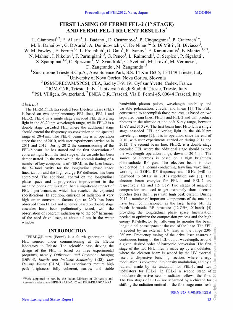
A schematic layout of FERMI FEL-2 is shown in Fig. 1. After completing the installation of the FEL-2 transport line in January 2012, its commissioning started beginning of February. At that time no undulators were installed yet to avoid risk of radiation damages during e-beam transport steering. In few shifts it was possible to get transport rates close to 100% of charge. Following this result the undulators of FEL-2 were installed during the Easter shutdown in April, as shown in Fig. 2.
Figure 1: Schematic layout of FERMI FEL-2.
Figure 2: The array of FEL-2 radiators on the left in the picture.
The FEL commissioning was constrained to the first
stage of the cascade, because the only diagnostics available were photon screens between the undulator
modules and the electron beam energy spectrometer, at the end of the undulator. No photon detectors capable of selectively measuring the emission from the second stage radiators were available.
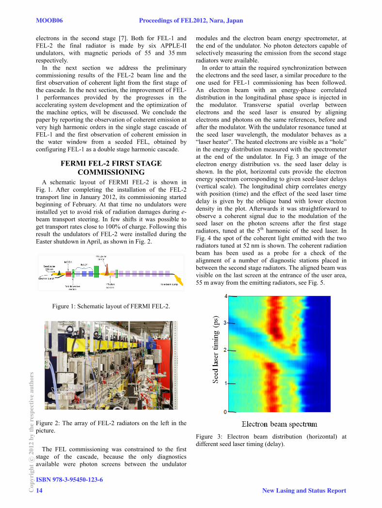
In order to attain the required synchronization between the electrons and the seed laser, a similar procedure to the one used for FEL-1 commissioning has been followed. An electron beam with an energy-phase correlated distribution in the longitudinal phase space is injected in the modulator. Transverse spatial overlap between electrons and the seed laser is ensured by aligning electrons and photons on the same references, before and after the modulator. With the undulator resonance tuned at the seed laser wavelength, the modulator behaves as a “laser heater”. The heated electrons are visible as a “hole” in the energy distribution measured with the spectrometer at the end of the undulator. In Fig. 3 an image of the electron energy distribution vs. the seed laser delay is shown. In the plot, horizontal cuts provide the electron energy spectrum corresponding to given seed-laser delays (vertical scale). The longitudinal chirp correlates energy with position (time) and the effect of the seed laser time delay is given by the oblique band with lower electron density in the plot. Afterwards it was straightforward to observe a coherent signal due to the modulation of the seed laser on the photon screens after the first stage radiators, tuned at the 5th harmonic of the seed laser. In Fig. 4 the spot of the coherent light emitted with the two radiators tuned at 52 nm is shown. The coherent radiation beam has been used as a probe for a check of the alignment of a number of diagnostic stations placed in between the second stage radiators. The aligned beam was visible on the last screen at the entrance of the user area, 55 m away from the emitting radiators, see Fig. 5.
Figure 3: Electron beam distribution (horizontal) at different seed laser timing (delay).
MOOB06 Proceedings of FEL2012, Nara, Japan
ISBN 978-3-95450-123-6
14Cop
yrig
htc ○
2012
byth
ere
spec
tive
auth
ors
New Lasing and Status Report
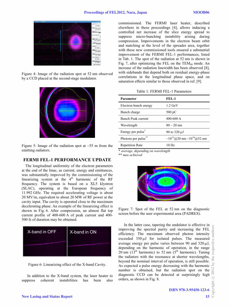
Figure 4: Image of the radiation spot at 52 nm observed by a CCD placed at the second-stage modulator.
Figure 5: Image of the radiation spot at ~55 m from the emitting radiators.
FERMI FEL-1 PERFORMANCE UPDATE The longitudinal uniformity of the electron parameters
at the end of the linac, as current, energy and emittances, was substantially improved by the commissioning of the linearizing system at the 4th harmonic of the RF frequency. The system is based on a XL5 klystron (SLAC), operating at the European frequency of 11.992 GHz. The required accelerating voltage is about 20 MV/m, equivalent to about 20 MW of RF power at the cavity input. The cavity is operated close to the maximum decelerating phase. An example of the linearizing effect is shown in Fig. 6. After compression, an almost flat top current profile of 400-600 A of peak current and 400-500 fs of duration may be obtained.
Figure 6: Linearizing effect of the X-band Cavity.
In addition to the X-band system, the laser heater to
suppress coherent instabilities has been also
commissioned. The FERMI laser heater, described elsewhere in these proceedings [4], allows inducing a controlled net increase of the slice energy spread to suppress micro-bunching instability arising during compression. Improvements in the electron beam orbit and matching at the level of the spreader area, together with these new commissioned tools ensured a substantial improvement of the FERMI FEL-1 performances, listed in Tab. 1. The spot of the radiation at 52 nm is shown in Fig. 7, after optimizing the FEL on the TEM00 mode. An increase of the radiation linewidth has been observed [8], with sidebands that depend both on residual energy-phase correlations in the longitudinal phase space, and on saturation effects similar to those observed in ref. [9].
Table 1: FERMI FEL-1 Parameters
Parameter FEL-1
Electron bunch energy 1.2 GeV
Bunch charge 500 pC
Bunch Peak current 400-600 A
Wavelength 80 – 20 nm
Energy per pulse* 90 to 320 J
Photons per pulse** ~1013@20 nm ~1014@52 nm
Repetition Rate 10 Hz
* average, depending on wavelength ** max achieved
Figure 7: Spot of the FEL at 52 nm on the diagnostic screen before the user experimental area (PADRES).
In the latter case, tapering the undulator is effective in
improving the spectral purity and increasing the FEL efficiency. The maximum observed photon intensity exceeded 350 J for isolated pulses. The measured average energy per pulse varies between 90 and 320 J, depending on the harmonic of operation, in the range 20 nm (13th harmonic) to 52 nm (5th harmonic). Tuning the radiators with the resonance at shorter wavelengths, beyond the nominal interval of operation, is still possible. As expected a pulse energy decreasing with the harmonic number is obtained, but the radiation spot on the diagnostic CCD can be detected at surprisingly high orders, as shown in Fig. 8.
Proceedings of FEL2012, Nara, Japan MOOB06
New Lasing and Status Report
ISBN 978-3-95450-123-6
15 Cop
yrig
htc ○
2012
byth
ere
spec
tive
auth
ors
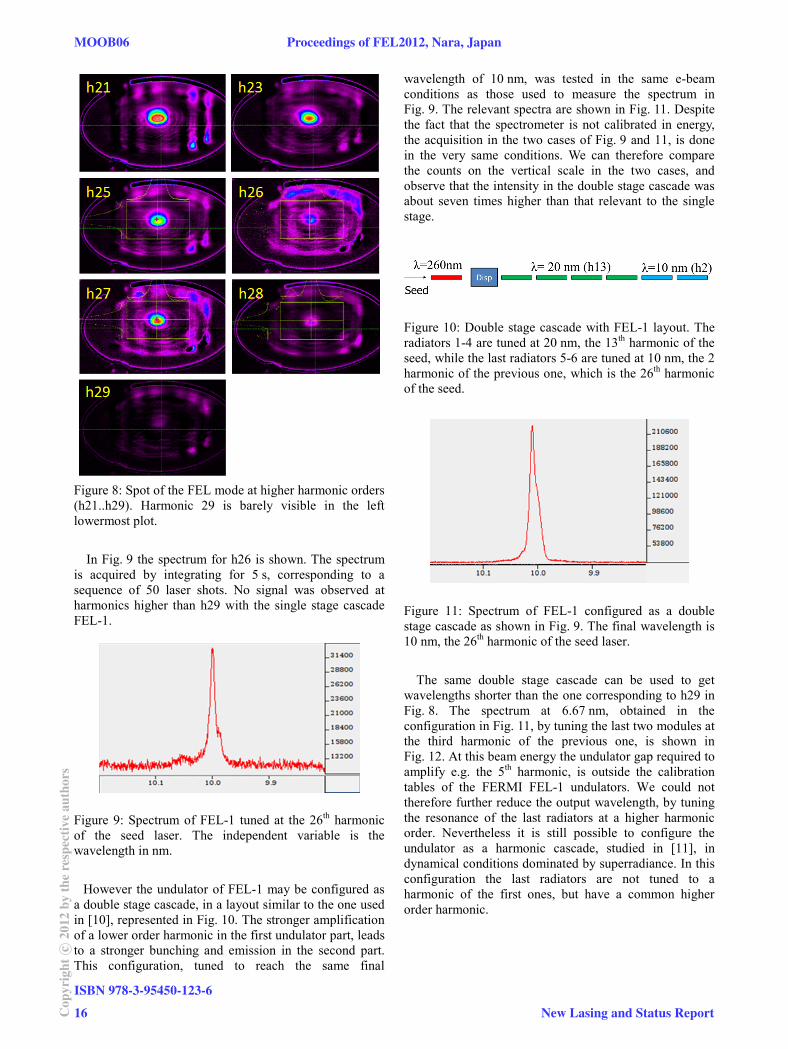
Figure 8: Spot of the FEL mode at higher harmonic orders (h21..h29). Harmonic 29 is barely visible in the left lowermost plot.
In Fig. 9 the spectrum for h26 is shown. The spectrum
is acquired by integrating for 5 s, corresponding to a sequence of 50 laser shots. No signal was observed at harmonics higher than h29 with the single stage cascade FEL-1.
Figure 9: Spectrum of FEL-1 tuned at the 26th harmonic of the seed laser. The independent variable is the wavelength in nm.
However the undulator of FEL-1 may be configured as
a double stage cascade, in a layout similar to the one used in [10], represented in Fig. 10. The stronger amplification of a lower order harmonic in the first undulator part, leads to a stronger bunching and emission in the second part. This configuration, tuned to reach the same final
wavelength of 10 nm, was tested in the same e-beam conditions as those used to measure the spectrum in Fig. 9. The relevant spectra are shown in Fig. 11. Despite the fact that the spectrometer is not calibrated in energy, the acquisition in the two cases of Fig. 9 and 11, is done in the very same conditions. We can therefore compare the counts on the vertical scale in the two cases, and observe that the intensity in the double stage cascade was about seven times higher than that relevant to the single stage.
Figure 10: Double stage cascade with FEL-1 layout. The radiators 1-4 are tuned at 20 nm, the 13th harmonic of the seed, while the last radiators 5-6 are tuned at 10 nm, the 2 harmonic of the previous one, which is the 26th harmonic of the seed.
Figure 11: Spectrum of FEL-1 configured as a double stage cascade as shown in Fig. 9. The final wavelength is 10 nm, the 26th harmonic of the seed laser.
The same double stage cascade can be used to get
wavelengths shorter than the one corresponding to h29 in Fig. 8. The spectrum at 6.67 nm, obtained in the configuration in Fig. 11, by tuning the last two modules at the third harmonic of the previous one, is shown in Fig. 12. At this beam energy the undulator gap required to amplify e.g. the 5th harmonic, is outside the calibration tables of the FERMI FEL-1 undulators. We could not therefore further reduce the output wavelength, by tuning the resonance of the last radiators at a higher harmonic order. Nevertheless it is still possible to configure the undulator as a harmonic cascade, studied in [11], in dynamical conditions dominated by superradiance. In this configuration the last radiators are not tuned to a harmonic of the first ones, but have a common higher order harmonic.
MOOB06 Proceedings of FEL2012, Nara, Japan
ISBN 978-3-95450-123-6
16Cop
yrig
htc ○
2012
byth
ere
spec
tive
auth
ors
New Lasing and Status Report
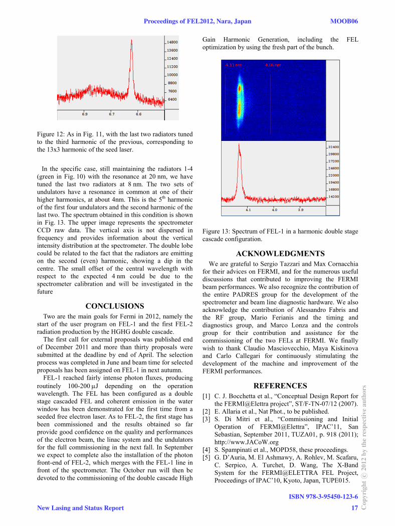
Figure 12: As in Fig. 11, with the last two radiators tuned to the third harmonic of the previous, corresponding to the 13x3 harmonic of the seed laser.
In the specific case, still maintaining the radiators 1-4
(green in Fig. 10) with the resonance at 20 nm, we have tuned the last two radiators at 8 nm. The two sets of undulators have a resonance in common at one of their higher harmonics, at about 4nm. This is the 5th harmonic of the first four undulators and the second harmonic of the last two. The spectrum obtained in this condition is shown in Fig. 13. The upper image represents the spectrometer CCD raw data. The vertical axis is not dispersed in frequency and provides information about the vertical intensity distribution at the spectrometer. The double lobe could be related to the fact that the radiators are emitting on the second (even) harmonic, showing a dip in the centre. The small offset of the central wavelength with respect to the expected 4 nm could be due to the spectrometer calibration and will be investigated in the future
CONCLUSIONS Two are the main goals for Fermi in 2012, namely the
start of the user program on FEL-1 and the first FEL-2 radiation production by the HGHG double cascade.
The first call for external proposals was published end of December 2011 and more than thirty proposals were submitted at the deadline by end of April. The selection process was completed in June and beam time for selected proposals has been assigned on FEL-1 in next autumn.
FEL-1 reached fairly intense photon fluxes, producing routinely 100-200 J depending on the operation wavelength. The FEL has been configured as a double stage cascaded FEL and coherent emission in the water window has been demonstrated for the first time from a seeded free electron laser. As to FEL-2, the first stage has been commissioned and the results obtained so far provide good confidence on the quality and performances of the electron beam, the linac system and the undulators for the full commissioning in the next fall. In September we expect to complete also the installation of the photon front-end of FEL-2, which merges with the FEL-1 line in front of the spectrometer. The October run will then be devoted to the commissioning of the double cascade High
Gain Harmonic Generation, including the FEL optimization by using the fresh part of the bunch.
Figure 13: Spectrum of FEL-1 in a harmonic double stage cascade configuration.
ACKNOWLEDGMENTS We are grateful to Sergio Tazzari and Max Cornacchia
for their advices on FERMI, and for the numerous useful discussions that contributed to improving the FERMI beam performances. We also recognize the contribution of the entire PADRES group for the development of the spectrometer and beam line diagnostic hardware. We also acknowledge the contribution of Alessandro Fabris and the RF group, Mario Ferianis and the timing and diagnostics group, and Marco Lonza and the controls group for their contribution and assistance for the commissioning of the two FELs at FERMI. We finally wish to thank Claudio Masciovecchio, Maya Kiskinova and Carlo Callegari for continuously stimulating the development of the machine and improvement of the FERMI performances.
REFERENCES [1] C. J. Bocchetta et al., “Conceptual Design Report for
the FERMI@Elettra project”, ST/F-TN-07/12 (2007). [2] E. Allaria et al., Nat Phot., to be published. [3] S. Di Mitri et al., “Commissioning and Initial
Operation of FERMI@Elettra”, IPAC’11, San Sebastian, September 2011, TUZA01, p. 918 (2011); http://www.JACoW.org
[4] S. Spampinati et al., MOPD58, these proceedings. [5] G. D’Auria, M. El Ashmawy, A. Rohlev, M. Scafaru,
C. Serpico, A. Turchet, D. Wang, The X-Band System for the FERMI@ELETTRA FEL Project, Proceedings of IPAC’10, Kyoto, Japan, TUPE015.
Proceedings of FEL2012, Nara, Japan MOOB06
New Lasing and Status Report
ISBN 978-3-95450-123-6
17 Cop
yrig
htc ○
2012
byth
ere
spec
tive
auth
ors
[6] P. Craievitch, M. Petronio, R. Vescovo, Deflecting Mode Optimization for a High energy Beam Diagnostic Tool, TH6REP063, Proceedings of PAC09, Vancouver, BC, Canada.
[7] I. Ben-Zvi, K.M. Yang, L.H. Yu, Nucl. Instr. and Meth. A 318 (1992) 726.
[8] E. Allaria et al., TUOB02, these proceedings. [9] L. Giannessi et al. PRL 108, 164801 (2012). [10] M. Labat et al. PRL 107, 224801 (2011). [11] L. Giannessi, P. Musumeci, New Journal of Physics 8
(2006) 294.
MOOB06 Proceedings of FEL2012, Nara, Japan
ISBN 978-3-95450-123-6
18Cop
yrig
htc ○
2012
byth
ere
spec
tive
auth
ors
New Lasing and Status Report