Embed Size (px)
Citation preview

S-72.3340 Optical Networks Course Lecture 10: Deployment
Considerations
Edward MutafungwaCommunications Laboratory, Helsinki University of Technology,
P. O. Box 2300, FIN-02015 TKK, FinlandTel: +358 9 451 2318, E-mail: [email protected]

18 Apr 2007 EMU/S-72.3340/DeploymentConsiderations/ Slide 2 of 63
Lecture Outline
IntroductionNetwork hierarchies
Global, backbone, metro, local access networksRights-of-way Fiber deployment optionsMiscellaneous networksConclusion

18 Apr 2007 EMU/S-72.3340/DeploymentConsiderations/ Slide 3 of 63
1. Introduction
Optical networks are now widely deployed in different environments
Special considerations have to be taken when deploying network infrastructure Environmental conditions Security Support facilities Cost Demand Legal considerations

18 Apr 2007 EMU/S-72.3340/DeploymentConsiderations/ Slide 4 of 63
2. Network Hierarchies
Figure: 3-D representation of the Layered Networks model.

18 Apr 2007 EMU/S-72.3340/DeploymentConsiderations/ Slide 5 of 63
2.1 Intercontinental Optical Networks
About 70% of earth’s surface covered by water bodies
For intercontinental (global) connectivity communication links must traverse water bodies Overhead in the sky via orbiting satellites Underwater using ”submarine cables”

18 Apr 2007 EMU/S-72.3340/DeploymentConsiderations/ Slide 6 of 63
2.1 Intercontinental Optical Networks
First submarine (copper) cable (1856-1920) Between Newfoundland and Ireland Telegraph connectivity

18 Apr 2007 EMU/S-72.3340/DeploymentConsiderations/ Slide 7 of 63
2.1 Intercontinental Optical Networks
First transatlantic (TAT-1) coaxial cable (1956-1978) Between Canada and UK Carried up to 48 voice circuits
Last (TAT-7) coaxial cable [1978-1994] Between USA and UK Carried up to 10500 voice circuits
Figure: Cross-sectional view of the TAT-1 cable 1956 (Source: National Museum of American History)

18 Apr 2007 EMU/S-72.3340/DeploymentConsiderations/ Slide 8 of 63
2.1 Intercontinental Optical Networks
First transatlantic (TAT-8) fiber cable (1988-2002) Between USA and France Standard singlemode fibers 1300 nm wavelength window Electrical regenerators Carried up to 40000 voice circuits (550 Mb/s aggregate
capacity) Expected to be filled by 2000, instead got filled up by
1990!
Figure: TAT-8 cable 1988 (Source: National Museum of American History)

18 Apr 2007 EMU/S-72.3340/DeploymentConsiderations/ Slide 9 of 63
2.1 Intercontinental Optical Networks Most recent fiber (TAT-14) fiber cable (2001-present)
Between USA, UK, France, Netherlands, Germany and Denmark Configured as a 4 fiber shared protection ring 16 protected WDM channels @ 10 Gbit/s (640 Gbit/s capacity) 1550 nm wavelength window operation EDFAs and non-zero dispersion shifted fibers used
Figure: TAT-14 landing points (Source: www.tat-14.com).

18 Apr 2007 EMU/S-72.3340/DeploymentConsiderations/ Slide 10 of 63
2.1 Intercontinental Optical Networks Majority (>75%) of intercontinental traffic now carried on fiber rather than satellite

18 Apr 2007 EMU/S-72.3340/DeploymentConsiderations/ Slide 11 of 63
2.2 Backbone Optical Networks Continental backbone network providing connectivity
between different countries
Figure: Level 3’s European backbone

18 Apr 2007 EMU/S-72.3340/DeploymentConsiderations/ Slide 12 of 63
2.2 Backbone Optical Networks National backbone network interconnecting cities and main
towns of a country
Figure: Conceptual backbone networks for Italy (left) and Belgium (right)
*Ref: R. Sabella et al, Journal of lightwave Technology, Vol. 16, No. 11, Nov. 1998

18 Apr 2007 EMU/S-72.3340/DeploymentConsiderations/ Slide 13 of 63
2.3 Optical Metro Networks
Provide connectivity within a city/metro or region
•San Antonio Metropolitan Fiber Network
•Time Warner Cables
•2400 km of fiber
•Ethernet, IP/MPLS
•Connectivity for corporate customers

18 Apr 2007 EMU/S-72.3340/DeploymentConsiderations/ Slide 14 of 63
2.4 Access Networks
Access network are “last leg” of telecommunications network Between service provider distribution facility and user’s
home or business Other names:
• last mile• local loop• first mile • etc.

18 Apr 2007 EMU/S-72.3340/DeploymentConsiderations/ Slide 15 of 63
2.4 Access Networks Access network now deregulated or unbundled
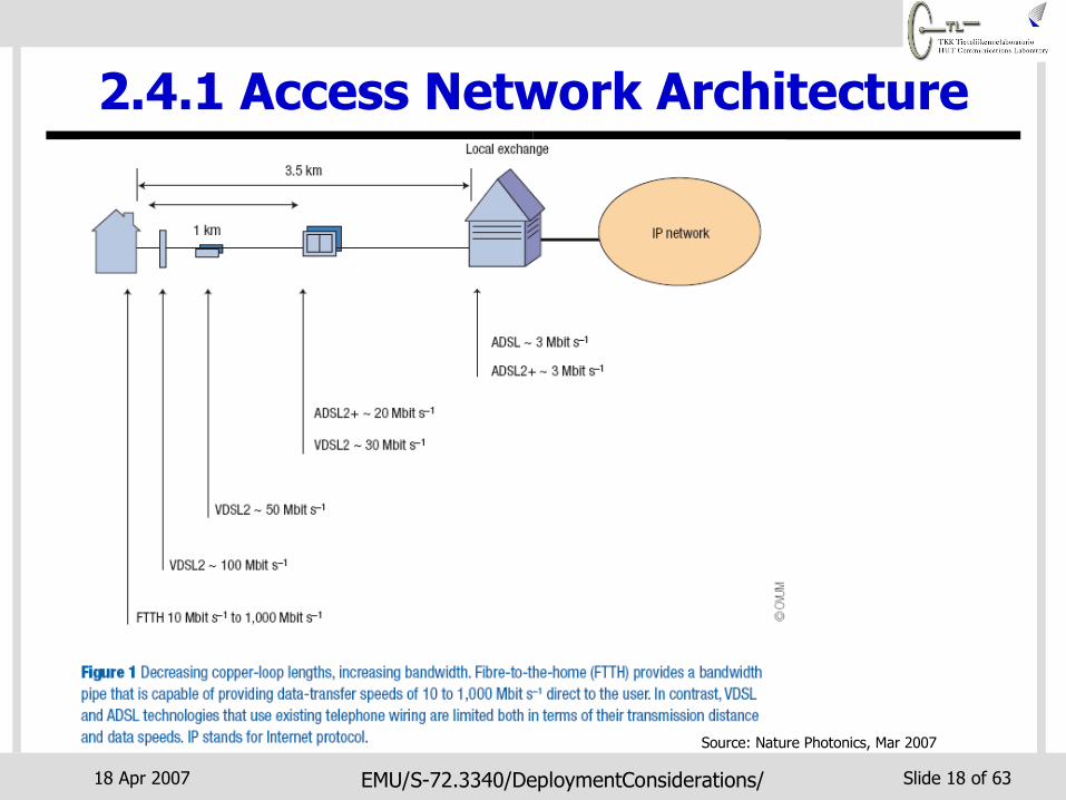
Great competition to deliver voice, video and internet services Service delivery possible via digital subscriber lines (DSL), cable
modems, broadband wireless, optical fibers etc.
Source: Nature Photonics, Mar 2007

18 Apr 2007 EMU/S-72.3340/DeploymentConsiderations/ Slide 16 of 63
2.4.1 Access Network Architecture Generally access networks consists of:
Hub ⇒ Central office, local exchange, headend etc. Remote nodes (RN) ⇒ Receives traffic from hubs and distributes to
NIUs Network interface units (NIU) ⇒ Located at user premises
Hub
RN
RN
RN
NIU
NIU
NIU
Feeder Distribution
Users

18 Apr 2007 EMU/S-72.3340/DeploymentConsiderations/ Slide 17 of 63
2.4.1 Access Network Architecture The optical terminating node in the access network is the
optical network unit (ONU) Differs from the NIU unless ONU is at user’s premises
RN
RN RN
ONU
FTT-Building
ONU/NIU
ONU/NIU
FTT-Home
RNRN
RN
Fiber Feeders
Interactive video
Digital Audio/TV
Telephony
Remote Games
Internet
Frame Relay
Service-Network Interface
Service/Content
Hub
RN = Remote Node NIU = Network Interface UnitONU = Optical Network Units FTT = Fiber to the-
RNONU
FTT-Air
ONU
RNRN ONU
Coaxial cables (cable TV)
Twisted pairs (xDSL)
FTT-Curb/Cabinet/Node
NIU
NIU
NIU
NIU
18 Apr 2007 EMU/S-72.3340/DeploymentConsiderations/ Slide 18 of 63
2.4.1 Access Network Architecture
Source: Nature Photonics, Mar 2007

18 Apr 2007 EMU/S-72.3340/DeploymentConsiderations/ Slide 19 of 63
2.4.2 Passive Optical Networks (PON)
The optical portion of the access network Must be simple Must easy/cheap to service
Optical networks preferred for access networks are called passive optical networks (PONs) Remote nodes ⇒ passive components (e.g. star
couplers) Reliable, easy to maintain and no need for powering Easy to upgrade without need to change the
infrastructure

18 Apr 2007 EMU/S-72.3340/DeploymentConsiderations/ Slide 20 of 63
2.4.2 Passive Optical Networks (PON)
Figure: Different PON types*Ref: N. Frigo, FTTH Presentation, AT&T Labs. Feb. 2004.

18 Apr 2007 EMU/S-72.3340/DeploymentConsiderations/ Slide 21 of 63
2.4.2 Passive Optical Networks (PON) WDM PONs at present mostly proprietary solutions Currently 3 main standards for power splitting PONs
IEEE EPON (gigabit Ethernet PON [GE-PON] in Japan) mostly deployed in Asia
North America and Europe operators opting for ITU-T PONs
Source: Nature Photonics, Mar 2007

18 Apr 2007 EMU/S-72.3340/DeploymentConsiderations/ Slide 22 of 63
3. Rights-of-Way
Deployment of fiber and equipment in LANs Simple, straightforward Building or premises usually
owned by the LAN operator No special permissions
required

18 Apr 2007 EMU/S-72.3340/DeploymentConsiderations/ Slide 23 of 63
3. Rights-of-Way More complicated to deploy
network infrastructure beyond operator’s own premises Equipment need to be suitably
housed at different sites Wireless links occupy some
frequency band that either requires a license or is license free
But linear facilities (transmission cables) need to be physically laid continuously between different sites
Figure: Example Helsinki-Tampere-Vaasa fiber link

18 Apr 2007 EMU/S-72.3340/DeploymentConsiderations/ Slide 24 of 63
3. Rights-of-Way
Network operators require rights-of-way Legal right to access the locations that are owned or
controlled by others
With rights-of-way an operator has following rights: Option to place facilities in the area covered by the
rights-of-way Construction and maintenance rights for installed
facilities Occupation or ongoing use of rights-of-way to do
business

18 Apr 2007 EMU/S-72.3340/DeploymentConsiderations/ Slide 25 of 63
3.1 Difficulties with Rights-of-Way
Similar challenges faced by other utility companies Power/gas suppliers, water, sewage etc.
Utility companies require access to various locations to deploy equipment or linear facilities Underground routes Tower sites Undersea routes Roads, highways etc. Buildings
These locations owned by local governments, private individuals, businesses, or even competitors

18 Apr 2007 EMU/S-72.3340/DeploymentConsiderations/ Slide 26 of 63
3.1 Difficulties with Rights-of-WayObtaining rights-of-way can be a very tedious,
costly and time-consuming process Environmental or archeological concerns Inconsistent regulations and bureaucracy in different
municipal or local authorities Complications with private landowners
• Deceased landowners• Family disputed land• Changing ownership• NIMBYs (Not-In-My-BackYard) etc.• Example: The German Network Development project had to
negotiate with 11,500 individual landowners when building a backbone network!

18 Apr 2007 EMU/S-72.3340/DeploymentConsiderations/ Slide 27 of 63
3.2 Utility Corridors Rights-of-way acquisition simplified by having utility
corridors Linear strips of land designated for use by utility companies
Utility corridors may provide rights-of-way for more than one purpose (telecom cables, pipelines etc.)
Corridor assembler/resellers provide a one-stop-shop for operator deploying networks over wide spans
Land X Land Y
Land Z
Site A
Site B Utility corridors

18 Apr 2007 EMU/S-72.3340/DeploymentConsiderations/ Slide 28 of 63
3.2 Utility Corridors Corridor owners may increase value of their assets by going
higher up the telecommunications value curve Revenues higher Increased exposures to investment risks Dark fiber is fiber which is currently not in use (lit)
Figure: The fiber optic telecommunications value curve Source: Public Utilities Fortnightly, July, 2002.

18 Apr 2007 EMU/S-72.3340/DeploymentConsiderations/ Slide 29 of 63
3.2 Utility Corridors Non-telecomm companies able to become service providers
Railway operator VR offering services via its subsidiary Corenet Ltd. Corenet and TeliaSonera provide capacity (STM-1 to STM-16, GbE)
to Finnish University Network (FUNET)
Figure: Corenet’s 5800 km mostly fiber backbone network laid along VR railway lines
Figure: FUNET backbone network (http://www.csc.fi/suomi/funet/verkko.html.en)

18 Apr 2007 EMU/S-72.3340/DeploymentConsiderations/ Slide 30 of 63
3.3 Equipment Location Equipment location
Operator’s sites Facilities collocation service
providers
Telehousing facilities requirements Sufficient floor space Protection from rodents, fire, leaks
etc. No-break power system Proximity to fiber plant Security against theft and
vandalism

18 Apr 2007 EMU/S-72.3340/DeploymentConsiderations/ Slide 31 of 63
4. Fiber Cable Deployment
Figure: Worldwide fiber cable deployment by region expressed in thousands of fiber-km (Source: KMI Research).
Telecomm and dot-com boom
Dot-com bubble burst, “bandwidth glut”
Emerging markets, FTTH deployment

18 Apr 2007 EMU/S-72.3340/DeploymentConsiderations/ Slide 32 of 63
4. Fiber Cable Deployment
Various methods exist for deployment of fiber cables
Selected cable deployment method depends on various factors Geographical topography of an area Availability of rights-of-way Time constraints Operator’s business strategy

18 Apr 2007 EMU/S-72.3340/DeploymentConsiderations/ Slide 33 of 63
4.1 Fiber Deployment Options Digging trenches specifically for burying fiber Cables
Well established technique also used for laying other infrastructure (gas pipeline, water pipes etc.)
Trenches usually 0.5 to 3.0 m deep Trenches made using trenchers, ditchers, plows etc.
Figure: Heavy duty ride-on trencher (Source: Vermeer).
Figure: Compact walk-behind trencher (Source: Ditch Witch).

18 Apr 2007 EMU/S-72.3340/DeploymentConsiderations/ Slide 34 of 63
4.1 Fiber Deployment Options Digging trenches has many disadvantages
Digging or excavation permits difficult to get and more costly Slow cable laying speed e.g. due to boulders encountered in digging Unsettling of humans and wildlife in their current habitat Possible accidents to passersby due to open trenches Damage to existing roads or buried infrastructure (cables, pipes etc.)
Figure: Damage to roads due to trenching
18 Apr 2007 EMU/S-72.3340/DeploymentConsiderations/ Slide 35 of 63
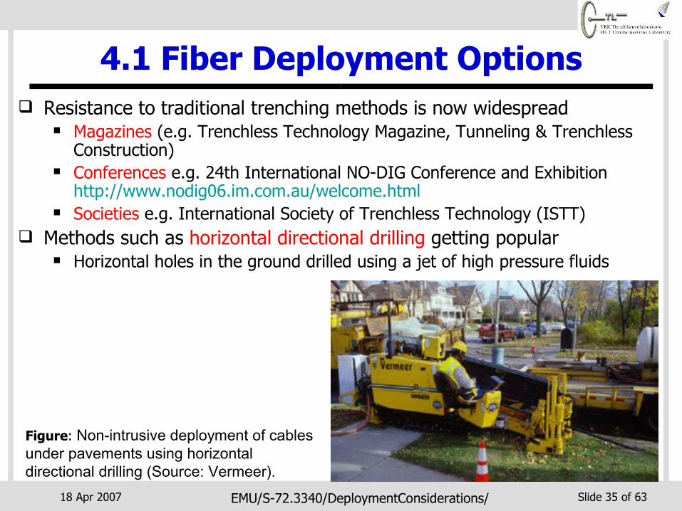
4.1 Fiber Deployment Options Resistance to traditional trenching methods is now widespread
Magazines (e.g. Trenchless Technology Magazine, Tunneling & Trenchless Construction)
Conferences e.g. 24th International NO-DIG Conference and Exhibition http://www.nodig06.im.com.au/welcome.html
Societies e.g. International Society of Trenchless Technology (ISTT) Methods such as horizontal directional drilling getting popular
Horizontal holes in the ground drilled using a jet of high pressure fluids
Figure: Non-intrusive deployment of cables under pavements using horizontal directional drilling (Source: Vermeer).

18 Apr 2007 EMU/S-72.3340/DeploymentConsiderations/ Slide 36 of 63
4.1 Fiber Deployment Options Collocating cables with other utility infrastructure
Extensive networks of infrastructure such as:• Power transmission and distribution lines• Potable water lines and irrigation pipelines• Natural gas, petroleum pipelines• Industrial waste lines, sewage and drainage systems
Well planned, maintained, almost similar routes to fiber cable routes Rights-of-way straightforward using existing utility corridor

18 Apr 2007 EMU/S-72.3340/DeploymentConsiderations/ Slide 37 of 63
4.1 Fiber Deployment Options
Figure: Fiber cables deployed on power transmission lines (source: Alcatel)
Figure: Fiber cables in sewage systems (source: CityNet, CableRunner)
Figure: Installation of fiber cables in natural gas pipes (Source Sempra Fiber Links).

18 Apr 2007 EMU/S-72.3340/DeploymentConsiderations/ Slide 38 of 63
4.1 Fiber Deployment OptionsPlacing fiber on transport networks
Networks for various transport modes for people and freight
• Railway lines (e.g. VR/Corenet)• Alongside motorways/freeways• Underground rail or road tunnels
Simplified rights-of-way and ready made routes

18 Apr 2007 EMU/S-72.3340/DeploymentConsiderations/ Slide 39 of 63
4.1 Fiber Deployment Options Fiber cabling using blown fiber techniques
Cables containing microducts only laid once Extra fibers when needed blown into microducts using compressed
air ⇒ reuse investment, pay-as-you-grow, no re-digging Up to 12 fibers could be blown into microducts simultaneously Used at Pentagon, Las Vegas (McCarren) International Airport,
University of Utah etc.
Figure: A conduit containing several microducts (left) and fibers blown into separate microducts (right). (Source: FiberDyne)

18 Apr 2007 EMU/S-72.3340/DeploymentConsiderations/ Slide 40 of 63
4.1 Fiber Deployment Options Underwater or submarine fiber cabling
For cable deployments in oceans, seas and inland waterways Avoid over digging in developed urban areas Provide nationwide connectivity for countries made of many Islands
Figure: Japan Information Highway (JIH) cable.
Figure: Neuf Cegetel has 200 km of underwater fiber in the River Seine waterway that runs through Paris.

18 Apr 2007 EMU/S-72.3340/DeploymentConsiderations/ Slide 41 of 63
4.1 Fiber Deployment Options Underwater or submarine fiber cabling

18 Apr 2007 EMU/S-72.3340/DeploymentConsiderations/ Slide 42 of 63
4.1 Fiber Deployment Options Underwater or submarine fiber cabling
Cable loaded onto ship and placed or buried in seabed
Figure: Feeding of cable onto ship storage (Canada, 2000)
Figure: Cable installation and maintenance ship (KDD, Japan)

18 Apr 2007 EMU/S-72.3340/DeploymentConsiderations/ Slide 43 of 63
4.2 Deployment in Metro Networks
Metro areas are usually heavily built already Trenchless/no-dig methods are extremely attractive Different local or municipal authorities institute measures
to reduce digging by multiple operators• Example: City of Milwaukee rents out space in city-owned
network of conduits• Example: City of Stockholm owns an optical network and rents
out capacities to various operators www.stokab.se

18 Apr 2007 EMU/S-72.3340/DeploymentConsiderations/ Slide 44 of 63
4.3 Deployment in Access Networks
Deployment of fiber in access network in fiber-to-the-home (FTTH) configuration
Plenty of bandwidth for end users but some disadvantages Competing technologies are already installed (e.g.
twisted pairs, coaxial cables) or tetherless (e.g. WLAN) Expensive because of reduced sharing of investment
costs Damage to infrastructure and environment if fiber is to
be buried

18 Apr 2007 EMU/S-72.3340/DeploymentConsiderations/ Slide 45 of 63
4.3 Deployment in Access Networks

18 Apr 2007 EMU/S-72.3340/DeploymentConsiderations/ Slide 46 of 63
4.3 Deployment in Access Networks Greenfield deployment allows
cable pre-installation Example: construction
companies (e.g. YIT, Sato) ensure fiber deployed to basement of new multiple tenant buildings
Brownfield deployment digging or aerial (cheaper) Bring fiber 1.5 km from home
and finish with copper links Many deployments in Japan, S.
Korea and USA Sonera HOASnet (FTT-Building)

18 Apr 2007 EMU/S-72.3340/DeploymentConsiderations/ Slide 47 of 63
5. Miscellaneous Networks
Optical networking technologies now used for various non-conventional applications
Introduce high-capacity and low signal loss advantages to new application environments
Need for some device modifications from traditional optical networks Different operating environment Unfamiliar traffic types

18 Apr 2007 EMU/S-72.3340/DeploymentConsiderations/ Slide 48 of 63
5.1 Intelligent Transportation Systems
Inter-Vehicle communications
Wide Area Wireless Communications
Road
side
-to-
Vehi
cle
Com
mun
icat
ions
Vehicles
Travelers
Roads/ Highways/ Streets
Transport Management Centers/ Content Providers
Wide Area Fixed Communications
On-Board Vehicle Communications

18 Apr 2007 EMU/S-72.3340/DeploymentConsiderations/ Slide 49 of 63
5.1 Intelligent Transportation Systems Optical technologies now used for on-board vehicles networks
Assisted driving, increased safety, entertainment and navigation purposes Networking cables and devices adapted for vehicular environment
Rugged (vibrations, dirt, moisture, chemicals etc.) Unpredictable (e.g. large temperature variation)

18 Apr 2007 EMU/S-72.3340/DeploymentConsiderations/ Slide 50 of 63
5.1 Intelligent Transportation Systems Various standards for optical on-board vehicle
communications FlexRay, MOST (Media Oriented Systems Transport), IDB-1394
(automotive version of IEEE-1394 or FireWire) Mostly use plastic optical fibers Peak rates: Flexray (10 Mb/s), MOST (24.8 Mb/s), IDB-1394 (400
Mb/s) Flexray for vehicle control, MOST and IDB-1394 for multimedia
applications
2006 BMW X5 Mercedes E-Class Saab 9-3 Audi A8
Flexray MOST

18 Apr 2007 EMU/S-72.3340/DeploymentConsiderations/ Slide 51 of 63
5.2 Avionics Fiber-Optics Fiber networks on planes
High capacity ⇒ in-flight entertainment, internet, control etc.
Long reach to various parts all plane sizes
Low weight ⇒ less fuel Small size
Challenges ”New technology” for flight
critical systems Vulnerability of fiber connectors
in extreme environments (temperature, vibrations etc.)
Example: Avionics Full-Duplex Ethernet/ARINC 664 standard 10 Mb/s (Copper), 100 Mb/s
(Copper or Fiber), GbE (future) Planned for A380s, 787s
Airbus A380
Boeing 787

18 Apr 2007 EMU/S-72.3340/DeploymentConsiderations/ Slide 52 of 63
5.3 Fiber Transmission for RF Networks
Fiber connecting distributed antenna systems Improved indoor coverage in malls,
underground parking, high-rise buildings etc.
Centralization of baseband processing functions ⇒ less complex remote RF processing in antenna units
Example products for cellular networks Toshiba’s RF Optical Distribution
System Ericsson’s Fiber Radio Solutions for
2G/3G networks
*Ref: http://www3.toshiba.co.jp/snis/ovs/rof_english/catalog/ROF_Leaflet001.pdf

18 Apr 2007 EMU/S-72.3340/DeploymentConsiderations/ Slide 53 of 63
5.3 Fiber Transmission for RF Networks
Backhaul links for signal transfer between base stations and switching centers Leased lines or self-owned point-to-point digital microwave links About 25% of operator’s OPEX and expensive to scale 3.5G networks could require up to 15 times more backhaul capacity
compared to 2G/2.5G networks 4G networks will increase requirements even further
Now use of fiber backhaul links increasingly attractive

18 Apr 2007 EMU/S-72.3340/DeploymentConsiderations/ Slide 54 of 63
5.3 Fiber Transmission for RF Networks
Fibers for collecting radio astronomy signals from radio telescopes and transporting them to observation point The wider the radio signal bandwidth the clearer the images Example e-MERLIN (UK): 6 telescopes spanning 217 km work as a
single giant telescope after being linked by fibers• 4 GHz bandwidth radio astronomy signal digitized and sent to Jodrell
Bank observation point over 30 Gb/s WDM fiber link (3×10 Gb/s)
*Ref: http://www.jb.man.ac.uk/news/connected/
Figure: Observed radio image
Figure: A 76 m radio telescope used in MERLIN
Figure: Fiber-linked e-MERLIN network.

18 Apr 2007 EMU/S-72.3340/DeploymentConsiderations/ Slide 55 of 63
5.4 Optical WirelessTransmission of infrared beams (optical signals) in
free space (fiberless) Also known as free space optics (FSO) Utilize conventional optical 1300/1550 nm transmitters
and receivers with some slight modifications

18 Apr 2007 EMU/S-72.3340/DeploymentConsiderations/ Slide 56 of 63
5.4 Optical Wireless
Advantages of FSO over fiber communications Tetherless flexibility Cost-effectiveness
Advantages of FSO over RF wireless communications Availability of large unregulated unlicensed bandwidth Data rates up to a several Gbit/s possible Links usually not affected by multipath fading
18 Apr 2007 EMU/S-72.3340/DeploymentConsiderations/ Slide 57 of 63
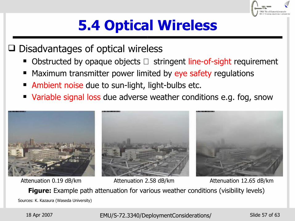
5.4 Optical Wireless Disadvantages of optical wireless
Obstructed by opaque objects ⇒ stringent line-of-sight requirement Maximum transmitter power limited by eye safety regulations Ambient noise due to sun-light, light-bulbs etc. Variable signal loss due adverse weather conditions e.g. fog, snow
Attenuation 0.19 dB/km
Sources: K. Kazaura (Waseda University)
Attenuation 2.58 dB/km Attenuation 12.65 dB/km
Figure: Example path attenuation for various weather conditions (visibility levels)
18 Apr 2007 EMU/S-72.3340/DeploymentConsiderations/ Slide 58 of 63
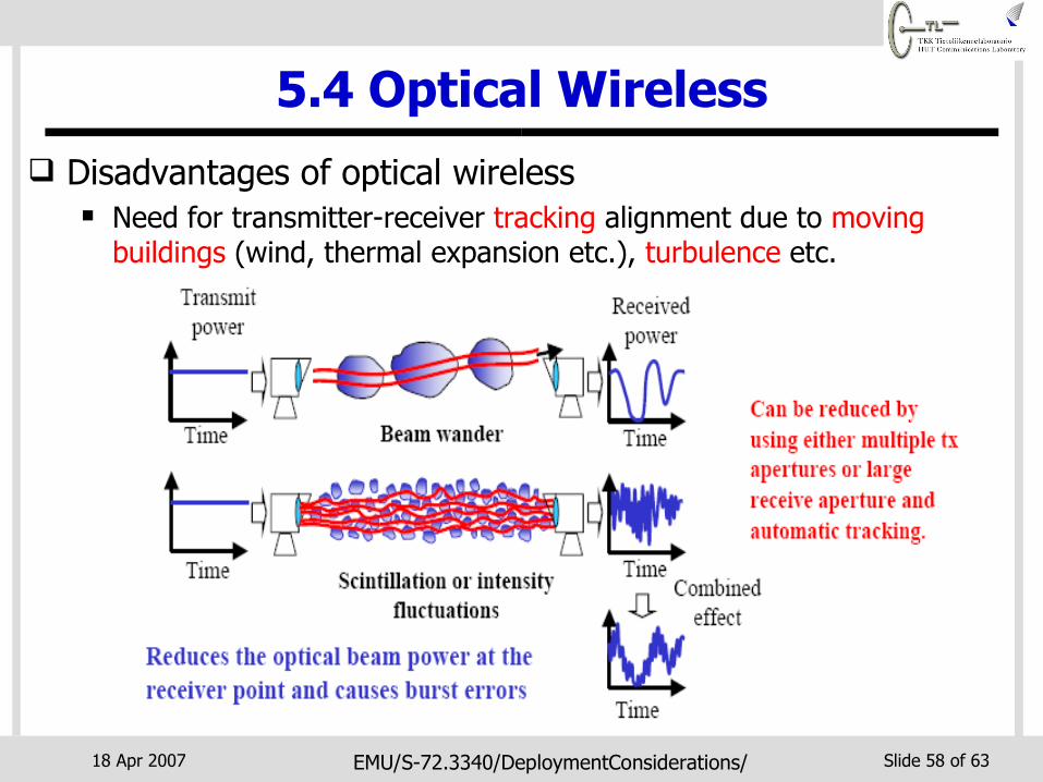
5.4 Optical Wireless Disadvantages of optical wireless
Need for transmitter-receiver tracking alignment due to moving buildings (wind, thermal expansion etc.), turbulence etc.
18 Apr 2007 EMU/S-72.3340/DeploymentConsiderations/ Slide 59 of 63
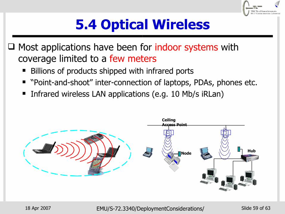
5.4 Optical Wireless Most applications have been for indoor systems with
coverage limited to a few meters Billions of products shipped with infrared ports “Point-and-shoot” inter-connection of laptops, PDAs, phones etc. Infrared wireless LAN applications (e.g. 10 Mb/s iRLan)
Node Hub
Ceiling Access Point

18 Apr 2007 EMU/S-72.3340/DeploymentConsiderations/ Slide 60 of 63
5.4 Optical Wireless Outdoor terrestrial FSO systems also gaining popularity
Advances in beam tracking and acquisition Rapid provisioning of multi-Gbit/s links for post-disaster recovery,
major sporting events, cellular back haul etc.
Sources: Waseda University, Hamamatsu Photonics, IEEE/ConTEL conference
Figure: Rooftop FSO installation

18 Apr 2007 EMU/S-72.3340/DeploymentConsiderations/ Slide 61 of 63
5.4 Optical Wireless Inter-satellite links also increasingly using optical wireless
technologies Orbiting satellites for broadband services require multi-Gb/s
interconnections
Earth
RF linkRF link
Optical/infrared link
Satellite Satellite
Earth station
Earth station

18 Apr 2007 EMU/S-72.3340/DeploymentConsiderations/ Slide 62 of 63
Conclusions
Optical networks are now an integral part of many current systems
Fiber likely to get even closer to the user e.g. fiber-to-the-desk
Next lecture on future directions of optical networking

18 Apr 2007 EMU/S-72.3340/DeploymentConsiderations/ Slide 63 of 63
?Thank You!