Embed Size (px)
Citation preview
National Fire Protection Association
1 Batterymarch Park, Quincy, MA 02169-7471
Phone: 617-770-3000 • Fax: 617-770-0700 • www.nfpa.org
FIRST DRAFT MEETING AGENDA
NFPA TECHNICAL COMMITTEE ON Emergency Power Supplies (EPS-AAA)
First Draft Meeting for 2019 Editions of NFPA 110 and 111
September 7, 2016
Teleconference / Web Meeting
Item No. Subject 16-9-1 Call to Order
16-9-2 Introduction of Members and Guests
16-9-3 Approval of Previous Meeting Minutes [Attachment]
16-9-4 Review of New Regs and Committee Actions
16-9-5 Task Group Reports
16-9-6 Processing of Public Inputs [Attachment]
16-9-7 Old Business
16-9-8 New Business
16-9-9 Adjournment
Page 1 of 67
Address List No PhoneEmergency Power Supplies EPS-AAA
National Electrical Code®
Christopher Coache08/11/2016
EPS-AAA
Dan Chisholm, Sr.
ChairMGI Systems, Inc.PO Box 2474Winter Park, FL 32790-2474
IM 10/1/1993EPS-AAA
David Stymiest
ChairSmith Seckman Reid, Inc.2995 Sidco DriveNashville, TN 37204
SE 1/12/2000
EPS-AAA
Herbert H. Daugherty
Secretary (Alternate)Electric Generating Systems Association6720 Ringold StreetMelbourne, FL 32940Electrical Generating Systems Association
M 4/5/2001EPS-AAA
Ernest E. Allen
PrincipalThe Doctors Company5001 Mayfield Road, Suite L55Lyndhurst, OH 44124NFPA Health Care Section
I 7/1/1990
EPS-AAA
Kenneth A. Cotton
PrincipalUS Energy/Donlee CropNetwork Operation Center140 East Stetson AveSuite 309Hemet, CA 92543Alternate: Joshua Dugger
M 10/1/1999EPS-AAA
Jason D'Antona
PrincipalThompson Consultants, Inc.525 Mill StreetMarion, MA 02738
SE 03/07/2013
EPS-AAA
David A. Dagenais
PrincipalWentworth-Douglass Hospital789 Central AvenueDover, NH 03820
U 08/09/2012EPS-AAA
Richard L. Day
PrincipalMichigan State Fire Marshal's Office207 Jackson StreetAllegan, MI 49010-9156
E 03/03/2014
EPS-AAA
Dennis DeMoss
PrincipalSargent & Lundy55 East Monroe StreetChicago, IL 60603Alternate: David C. Skiba
SE 1/1/1990EPS-AAA
William H. Everard
PrincipalEverard Mid Atlantic Inc.5712 General Washington Drive, Suite EAlexandria, VA 22312-2419
SE 1/1/1979
EPS-AAA
Louis J. Feller
PrincipalUS Army Corps of Engineers8212 126th Place SENewcastle, WA 98056-9132
U 03/03/2014EPS-AAA
James R. (Skip) Gregory
PrincipalHealth Facility Consulting4128 Zermatt DriveTallahassee, FL 32303-2252Florida Agency for Health Care Administration
E 3/21/2006
EPS-AAA
Ross M. Hardy
PrincipalThe University of Michigan Medical CenterPlant Hospital Maintenance1500 East Medical Center DriveAnn Arbor, MI 48073-6712
U 7/14/2004EPS-AAA
Jonathan Hartsell
PrincipalRodgers5701 North Sharon Amity RoadCharlotte, NC 28215
IM 07/29/2013
1Page 2 of 67
Address List No PhoneEmergency Power Supplies EPS-AAA
National Electrical Code®
Christopher Coache08/11/2016
EPS-AAA
James Hunt
PrincipalHOTSTART Inc.5723 East AlkiSpokane, WA 99212Electrical Generating Systems Association
M 08/03/2016EPS-AAA
Chad E. Loomis
PrincipalCornell University2336 South Balch HallIthaca, NY 14853
U 3/2/2010
EPS-AAA
Alan Manche
PrincipalSchneider Electric1601 Mercer RoadLexington, KY 40511-1025
M 10/23/2003EPS-AAA
George Mills
PrincipalThe Joint CommissionDepartment of EngineeringOne Renaissance BoulevardOakbrook Terrace, IL 60181Joint Commission on Accreditation HealthcareOrganizations
E 3/15/2007
EPS-AAA
Hugh O. Nash, Jr.
PrincipalNash-Consult964 General George Patton RoadNashville, TN 37221Alternate: Bogue M. Waller
SE 10/3/2002EPS-AAA
Michael D. Niclaus
PrincipalGregory Poole Power Systems CAT7309 Liserin Woods LaneFuquay Varina, NC 27526-5886
IM 03/03/2014
EPS-AAA
Daniel J. O'Connor
PrincipalJensen Hughes/AON Fire Protection Engineering4 Overlook PointLincolnshire, IL 60069-4302Alternate: Raymond J. Battalora
I 1/1/1984EPS-AAA
Gary L. Olson
PrincipalkW Rx, LLC12979 Killdeer Street NWMinneapolis, MN 55448-7018
SE 08/09/2011
EPS-AAA
Ralph E. Patterson
PrincipalPower Products & Solutions Inc.PO Box 691210Charlotte, NC 28227InterNational Electrical Testing Association
IM 7/28/2006EPS-AAA
Steve R. Sappington
PrincipalCaterpillar Inc.175 Cutstone CourtFayetteville, GA 30215-6206
M 08/11/2014
EPS-AAA
Ronald A. Schroeder
PrincipalASCO Power Technologies, LP50 Hanover RoadFlorham Park, NJ 07932Alternate: Brian J. Escott
M 1/10/2008EPS-AAA
Randy H. Schubert
PrincipalEricsson444 Hoes LanePiscataway, NJ 08854-4104Alliance for Telecommunications Industry SolutionsAlternate: Richard G. Kluge
U 12/08/2015
2Page 3 of 67
Address List No PhoneEmergency Power Supplies EPS-AAA
National Electrical Code®
Christopher Coache08/11/2016
EPS-AAA
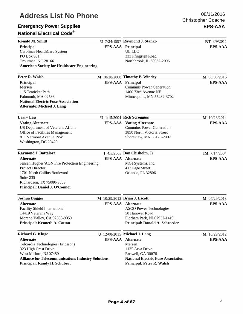
Ronald M. Smidt
PrincipalCarolinas HealthCare SystemPO Box 901Troutman, NC 28166American Society for Healthcare Engineering
U 7/24/1997EPS-AAA
Raymond J. Stanko
PrincipalUL LLC333 Pfingsten RoadNorthbrook, IL 60062-2096
RT 8/9/2011
EPS-AAA
Peter R. Walsh
PrincipalMersen115 Teaticket PathFalmouth, MA 02536National Electric Fuse AssociationAlternate: Michael J. Lang
M 10/28/2008EPS-AAA
Timothy P. Windey
PrincipalCummins Power Generation1400 73rd Avenue NEMinneapolis, MN 55432-3702
M 08/03/2016
EPS-AAA
Larry Lau
Voting AlternateUS Department of Veterans AffairsOffice of Facilities Management811 Vermont Avenue, NWWashington, DC 20420
U 1/15/2004EPS-AAA
Rich Scroggins
Voting AlternateCummins Power Generation3850 North Victoria StreetShoreview, MN 55126-2907
M 10/28/2014
EPS-AAA
Raymond J. Battalora
AlternateJensen Hughes/AON Fire Protection EngineeringProject Director1701 North Collins BoulevardSuite 235Richardson, TX 75080-3553Principal: Daniel J. O'Connor
I 4/3/2003EPS-AAA
Dan Chisholm, Jr.
AlternateMGI Systems, Inc.412 Page StreetOrlando, FL 32806
IM 7/14/2004
EPS-AAA
Joshua Dugger
AlternateFacility Shield International14419 Veterans WayMoreno Valley, CA 92553-9059Principal: Kenneth A. Cotton
M 10/29/2012EPS-AAA
Brian J. Escott
AlternateASCO Power Technologies50 Hanover RoadFlorham Park, NJ 07932-1419Principal: Ronald A. Schroeder
M 07/29/2013
EPS-AAA
Richard G. Kluge
AlternateTelcordia Technologies (Ericsson)323 High Crest DriveWest Milford, NJ 07480Alliance for Telecommunications Industry SolutionsPrincipal: Randy H. Schubert
U 12/08/2015EPS-AAA
Michael J. Lang
AlternateMersen1135 Arva DriveRoswell, GA 30076National Electric Fuse AssociationPrincipal: Peter R. Walsh
M 10/29/2012
3Page 4 of 67
Address List No PhoneEmergency Power Supplies EPS-AAA
National Electrical Code®
Christopher Coache08/11/2016
EPS-AAA
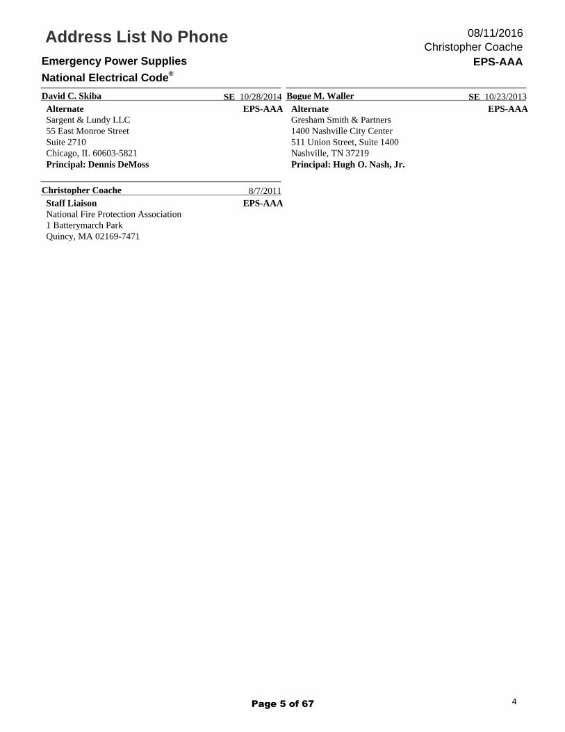
David C. Skiba
AlternateSargent & Lundy LLC55 East Monroe StreetSuite 2710Chicago, IL 60603-5821Principal: Dennis DeMoss
SE 10/28/2014EPS-AAA
Bogue M. Waller
AlternateGresham Smith & Partners1400 Nashville City Center511 Union Street, Suite 1400Nashville, TN 37219Principal: Hugh O. Nash, Jr.
SE 10/23/2013
EPS-AAA
Christopher Coache
Staff LiaisonNational Fire Protection Association1 Batterymarch ParkQuincy, MA 02169-7471
8/7/2011
4Page 5 of 67
National Fire Protection Association 1 Batterymarch Park, Quincy, MA 02169-7471 Phone: 617-770-3000 • Fax: 617-770-0700 • www.nfpa.org
Page 6 of 67

Page 7 of 67
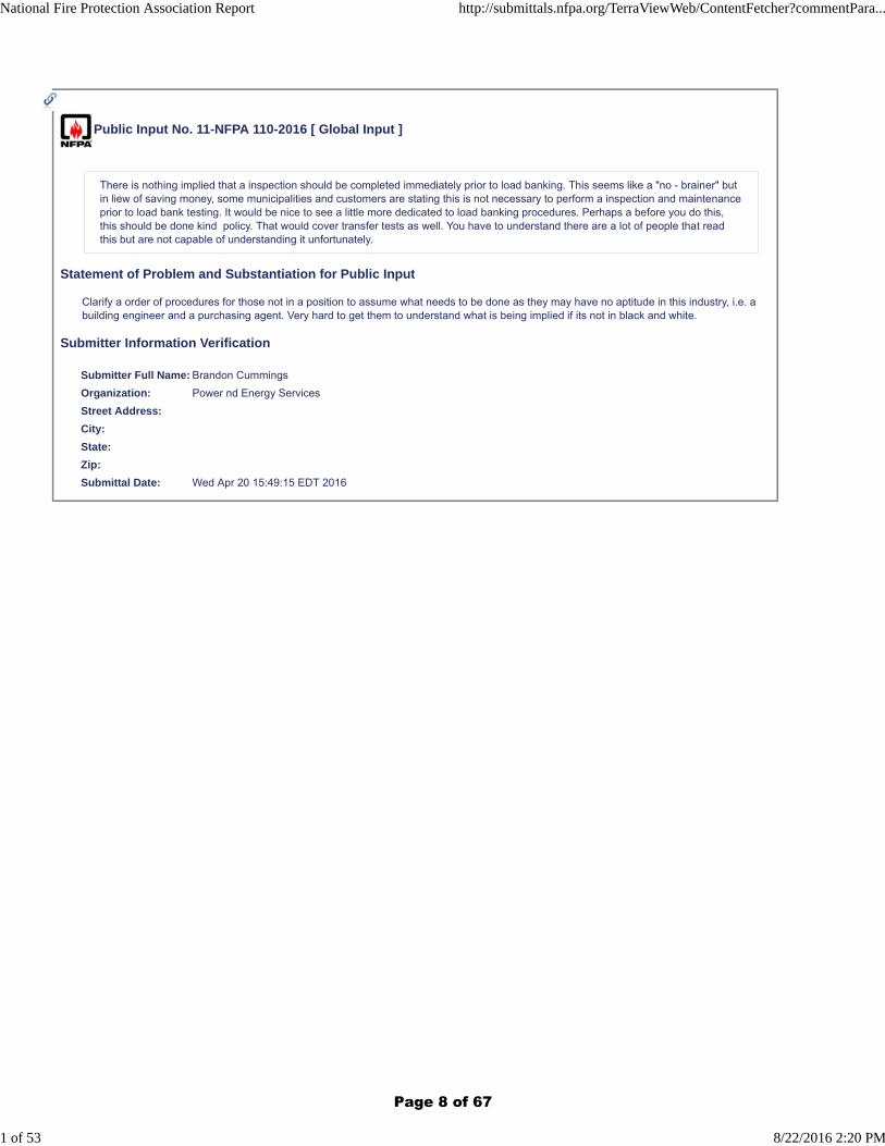
Public Input No. 11-NFPA 110-2016 [ Global Input ]
There is nothing implied that a inspection should be completed immediately prior to load banking. This seems like a "no - brainer" butin liew of saving money, some municipalities and customers are stating this is not necessary to perform a inspection and maintenanceprior to load bank testing. It would be nice to see a little more dedicated to load banking procedures. Perhaps a before you do this,this should be done kind policy. That would cover transfer tests as well. You have to understand there are a lot of people that readthis but are not capable of understanding it unfortunately.
Statement of Problem and Substantiation for Public Input
Clarify a order of procedures for those not in a position to assume what needs to be done as they may have no aptitude in this industry, i.e. a building engineer and a purchasing agent. Very hard to get them to understand what is being implied if its not in black and white.
Submitter Information Verification
Submitter Full Name: Brandon Cummings
Organization: Power nd Energy Services
Street Address:
City:
State:
Zip:
Submittal Date: Wed Apr 20 15:49:15 EDT 2016
National Fire Protection Association Report http://submittals.nfpa.org/TerraViewWeb/ContentFetcher?commentPara...
1 of 53 8/22/2016 2:20 PM
Page 8 of 67
Public Input No. 18-NFPA 110-2016 [ Section No. 1.1.3 ]
1.1.3
This standard does not cover the following:
(1) Application of the EPSS
(2) Emergency lighting unit equipment
(3) Distribution wiring
(4) Utility service when such service is permitted as the EPSS
(5) Parameters for stored energy devices
(6) The equipment of systems that are not classed as Level 1 or Level 2 systems in accordance with Chapter 4 of this standard
Statement of Problem and Substantiation for Public Input
The revised wording provides clarification that equipment that is connected to an EPSS that does not serve Level 1 and Level 2 loads in not within the scope of the standard. We have a Level 1 generator that has multiple ATSs. Only one of the ATSs serves Level 1 loads. The existing wording of 'equipment of systems' seems to imply that the boundary of the EPSS includes the ancillary equipment that does not serve Level 1 or Level 2 loads. The revised wording uses the term EPSS to be consistent with other sections of the standard. Additional information could be added with annex material as follows:
1.1.3(6)* Where multiple ATSs are connected to a Level 1 or Level 2 generators, only the ATSs that serve Level 1 or Level 2 electrical loads are within the scope of this standard. ATSs that do not serve Level 1 or Level 2 electrical loads are not within the scope of the standard. However, the electrical loads served by other than Level 1 and Level 2 ATSs can be used to provide electrical loading of the generator required in Section 8.
Submitter Information Verification
Submitter Full Name: Tom Christman
Organization: Self-employeed
Affilliation: None
Street Address:
City:
State:
Zip:
Submittal Date: Wed May 04 15:39:22 EDT 2016
National Fire Protection Association Report http://submittals.nfpa.org/TerraViewWeb/ContentFetcher?commentPara...
2 of 53 8/22/2016 2:20 PM
Page 9 of 67
Public Input No. 24-NFPA 110-2016 [ Section No. 3.3.4 ]
3.3.4* Emergency Power Supply System (EPSS).
A complete functioning EPS system coupled to a system of conductors, disconnecting means and overcurrent protective devices,transfer switches, and all control, supervisory, and support devices up to and including the load terminals of the transfer equipmentneeded for the system to operate as a safe and reliable source of electric power.
3.3.4.1 Multiple Generators Operating on a Common Bus. When multiple generators are connected together on a common bus,the common bus between the generators shall be considered to be the system source.
Statement of Problem and Substantiation for Public Input
When generators are connected together to provide a common source for the system, many potential issues can come into play, since the most NFPA standards are written around the design of systems that are primarily radial in nature and utilize a single utility source for the system. Recognizing the system bus for multiple generator systems will clarify design requirements for things such as grounding and bonding of the system, and selective coordination of the distribution system connected to the generator source.
Note also that rather than here, this change could be made in 3.3.3.
Submitter Information Verification
Submitter Full Name: Gary Olson
Organization: kW Rx, LLC
Street Address:
City:
State:
Zip:
Submittal Date: Wed Jun 15 11:31:30 EDT 2016
National Fire Protection Association Report http://submittals.nfpa.org/TerraViewWeb/ContentFetcher?commentPara...
3 of 53 8/22/2016 2:20 PM
Page 10 of 67

Public Input No. 51-NFPA 110-2016 [ Section No. 4.4 [Excluding any Sub-Sections] ]
This standard recognizes two levels of for equipment installation, performance, and maintenance requirements .
Statement of Problem and Substantiation for Public Input
The original sentence is confusing and incomplete.
To correct, need to replace the word "of" with "for", and then add "requirements" to the end of the sentence.
Submitter Information Verification
Submitter Full Name: Timothy Windey
Organization: Cummins Power Generation
Street Address:
City:
State:
Zip:
Submittal Date: Mon Jun 27 10:37:42 EDT 2016
National Fire Protection Association Report http://submittals.nfpa.org/TerraViewWeb/ContentFetcher?commentPara...
4 of 53 8/22/2016 2:20 PM
Page 11 of 67
Public Input No. 62-NFPA 110-2016 [ Section No. 5.2.1 [Excluding any Sub-Sections] ]
Energy converters shall consist only of rotating equipment as indicated in 5.2.4,or fuel cells as described in NFPA 853, Standard forInstallation of Stationary Fuel Cell Power Systems .
Statement of Problem and Substantiation for Public Input
“I am the former chair and a current member of the committee responsible for writing the electrical chapters for NFPA 99. As such, it is our responsibility to determine and publish the performance requirements for health care facilities. As such, we have determined that fuel cells, with a properly designed system (i.e. N+1 to account for potential failure and continuously running to accommodate start-up time) are an acceptable power source to supply power to the essential electrical systems in health facilities. Indeed, due to their low emissions, reliability, and power quality, they are a better power source than most utilities or other standby power options.
Furthermore, increasing numbers of buildings of all types are now using fuel cells as an on-site generation source. I have personally been the engineer of record for a number of systems supplying NORMAL power for Kaiser Permanente. These systems, and many others in different building types, have proven themselves to be reliable sources of power.
We have submitted this proposal to align NFPA 110 with our document, and to better coordinate. I will be happy to work with the 110 committee to facilitate document coordination.”
Related Public Inputs for This Document
Related Input Relationship
Public Input No. 61-NFPA 110-2016 [Section No. 5.4]
Submitter Information Verification
Submitter Full Name: Walter Vernon
Organization: Mazzetti
Street Address:
City:
State:
Zip:
Submittal Date: Wed Jun 29 16:17:03 EDT 2016
National Fire Protection Association Report http://submittals.nfpa.org/TerraViewWeb/ContentFetcher?commentPara...
5 of 53 8/22/2016 2:20 PM
Page 12 of 67
Public Input No. 14-NFPA 110-2016 [ Section No. 5.2.1.2 ]
5.2.1.2
The capability of the energy converter, with its controls and accessories, to survive without damage from common and abnormaldisturbances in actual load circuits shall be demonstrable by tests on separate prototype models, or by acceptable tests on thesystem components as performed by the component suppliers, or by tests performed in the listing process for the assembly.
5.2.1.2.1
The energy converter for Level 1 systems shall be specifically designed, assembled, and tested to ensure durability, reliability, andproper system operation. Testing shall include:
(1) Endurance testing of the assembled prototype to demonstrate proper operation and acceptable equipment life under typicalstandby duty cycle conditions.
FPN: Typical duty cycle requirements for standby installations can be found in ISO 8528.
(2) Short circuits, including phase to ground, phase to phase, and all phase bolted faults.
(3) Stable operation and acceptable performance due to sudden load application and rejection.
(4) Stable operation and acceptable waveform quality while operating non-linear loads such as silicon-controlled rectifiers.
(5) Stable operation and acceptable waveform quality while operating medical equipment.
(6) Proper operation, without nuisance tripping, of critical protective equipment including engine overspeed, over temperature due toalternator overload, and engine overload conditions.
(7) Demonstration of reliable starting and proper operation under sustained load conditions at the rated temperature extremes for theequipment.
(8) Demonstration by test that the machine is torsionally sound.
Statement of Problem and Substantiation for Public Input
It seems odd to me that the requirements for prototype testing are separated from the paragraph that requires them. So, I have suggested moving them to a sub-paragraph to the primary requirement, which is 5.2.1.2. That change is not critical but it does make the requirements easier to understand and find.
I don't believe the text of the actual prototype requirements have been modified for a long time. Note that many of these tests require testing of the assembled machine to validate, so text was added to make that more clear. For example, short circuit testing of an alternator alone does not qualify the generator set as being able to withstand a short circuit. The actual testing requirements are intended to be guidelines, but given advances in technology and engineering, I think they could be more specific so have made changes to the actual tests:
1. Endurance testing was added, because endurance tests are the only way to validate capability of the assembled product to operate properly in spite of vibration, load levels, etc. Generator engines for standby applications are "hot rods" in that they are designed to operate at high load levels for relatively short life spans compared to most engine powered equipment, so it seems reasonable that they would have some validation of life span in a standby environment. An endurance run is particularly useful in validating design for difficult to evaluate conditions, such as vibration characteristics.
2. The short circuit requirement was not specific as to what short circuit tests should be completed. Short circuits of different types impose different stresses on the assembled equipment, so it is reasonable to require that all types of short circuits be tested.
3. This text was added to require that actual testing of an assembled product for transient performance and stability is completed. Transient testing establishes a baseline for production equipment performance and validates the normal range of loads that can be applied while maintaining acceptable voltage and frequency.
4, 5. These paragraphs are mechanisms to provide not only a provision for stable operation, but to allow a designer to have data on the limits of the equipment when exposed to non-linear loads and specialized medical equipment. Note that there is no requirement that requires testing to verify that the medical equipment operates, only that the generator equipment is stable. A designer would be required to understand the operating limits of the loads and specify performance that allows the loads to operate.
6. Text of this requirement was expanded to make it clear that the requirement was not only to have protection, but to be sure that it does not nuisance trip, which is particularly critical in Level 1 applications.
7. In general, it is not possible to verify proper operation under adverse temperature conditions in factory or site testing because the tests are not done in an environment that is temperature or elevation controlled, so prototype testing is necessary to validate a design.
8. When the text requiring torsional compatibility was written, there was not test equipment commonly available to test for torsional compatibility. However, now there is, and a torsional test to verify compatibility is not an unreasonable requirement, since calculations will always lack the confidence of actual testing.
Related Public Inputs for This Document
National Fire Protection Association Report http://submittals.nfpa.org/TerraViewWeb/ContentFetcher?commentPara...
6 of 53 8/22/2016 2:20 PM
Page 13 of 67
Related Input Relationship
Public Input No. 13-NFPA 110-2016 [Section No. 5.2.3]
Submitter Information Verification
Submitter Full Name: Gary Olson
Organization: kW Rx, LLC
Street Address:
City:
State:
Zip:
Submittal Date: Fri Apr 22 12:49:21 EDT 2016
National Fire Protection Association Report http://submittals.nfpa.org/TerraViewWeb/ContentFetcher?commentPara...
7 of 53 8/22/2016 2:20 PM
Page 14 of 67
Public Input No. 12-NFPA 110-2016 [ Section No. 5.2.1.3 ]
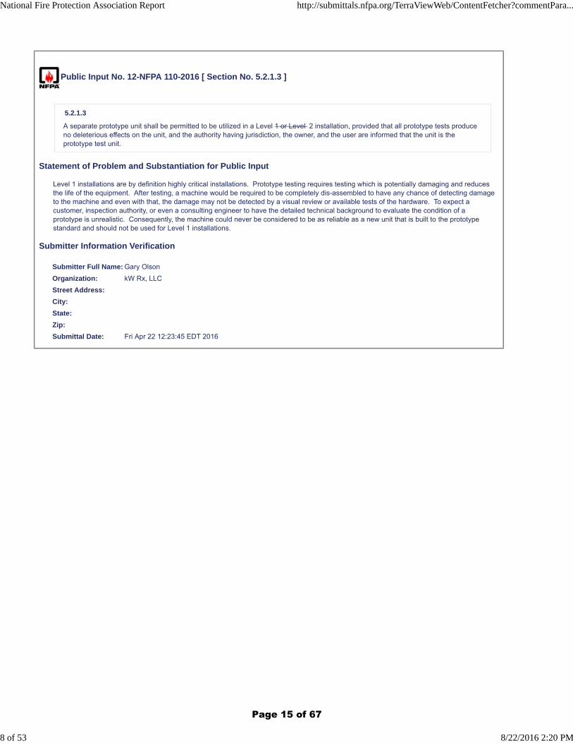
5.2.1.3
A separate prototype unit shall be permitted to be utilized in a Level 1 or Level 2 installation, provided that all prototype tests produceno deleterious effects on the unit, and the authority having jurisdiction, the owner, and the user are informed that the unit is theprototype test unit.
Statement of Problem and Substantiation for Public Input
Level 1 installations are by definition highly critical installations. Prototype testing requires testing which is potentially damaging and reduces the life of the equipment. After testing, a machine would be required to be completely dis-assembled to have any chance of detecting damage to the machine and even with that, the damage may not be detected by a visual review or available tests of the hardware. To expect a customer, inspection authority, or even a consulting engineer to have the detailed technical background to evaluate the condition of a prototype is unrealistic. Consequently, the machine could never be considered to be as reliable as a new unit that is built to the prototype standard and should not be used for Level 1 installations.
Submitter Information Verification
Submitter Full Name: Gary Olson
Organization: kW Rx, LLC
Street Address:
City:
State:
Zip:
Submittal Date: Fri Apr 22 12:23:45 EDT 2016
National Fire Protection Association Report http://submittals.nfpa.org/TerraViewWeb/ContentFetcher?commentPara...
8 of 53 8/22/2016 2:20 PM
Page 15 of 67
Public Input No. 13-NFPA 110-2016 [ Section No. 5.2.3 ]
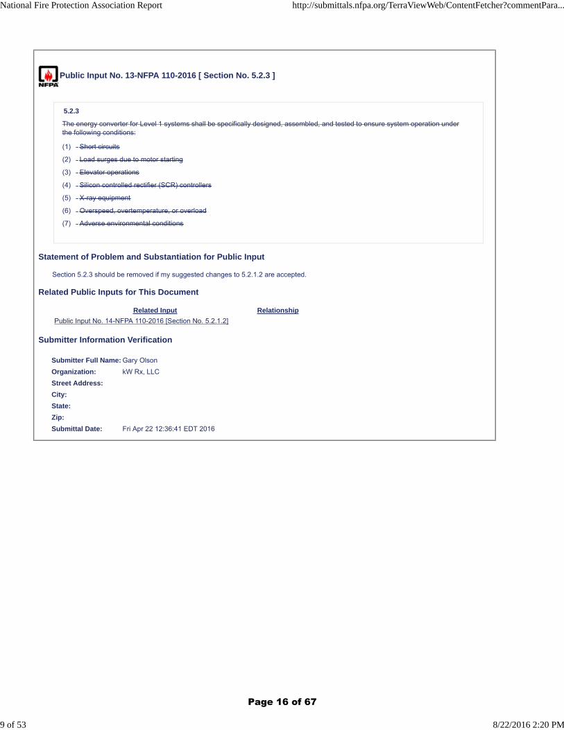
5.2.3
The energy converter for Level 1 systems shall be specifically designed, assembled, and tested to ensure system operation underthe following conditions:
(1) Short circuits
(2) Load surges due to motor starting
(3) Elevator operations
(4) Silicon controlled rectifier (SCR) controllers
(5) X-ray equipment
(6) Overspeed, overtemperature, or overload
(7) Adverse environmental conditions
Statement of Problem and Substantiation for Public Input
Section 5.2.3 should be removed if my suggested changes to 5.2.1.2 are accepted.
Related Public Inputs for This Document
Related Input Relationship
Public Input No. 14-NFPA 110-2016 [Section No. 5.2.1.2]
Submitter Information Verification
Submitter Full Name: Gary Olson
Organization: kW Rx, LLC
Street Address:
City:
State:
Zip:
Submittal Date: Fri Apr 22 12:36:41 EDT 2016
National Fire Protection Association Report http://submittals.nfpa.org/TerraViewWeb/ContentFetcher?commentPara...
9 of 53 8/22/2016 2:20 PM
Page 16 of 67
Public Input No. 25-NFPA 110-2016 [ Section No. 5.3.5 ]
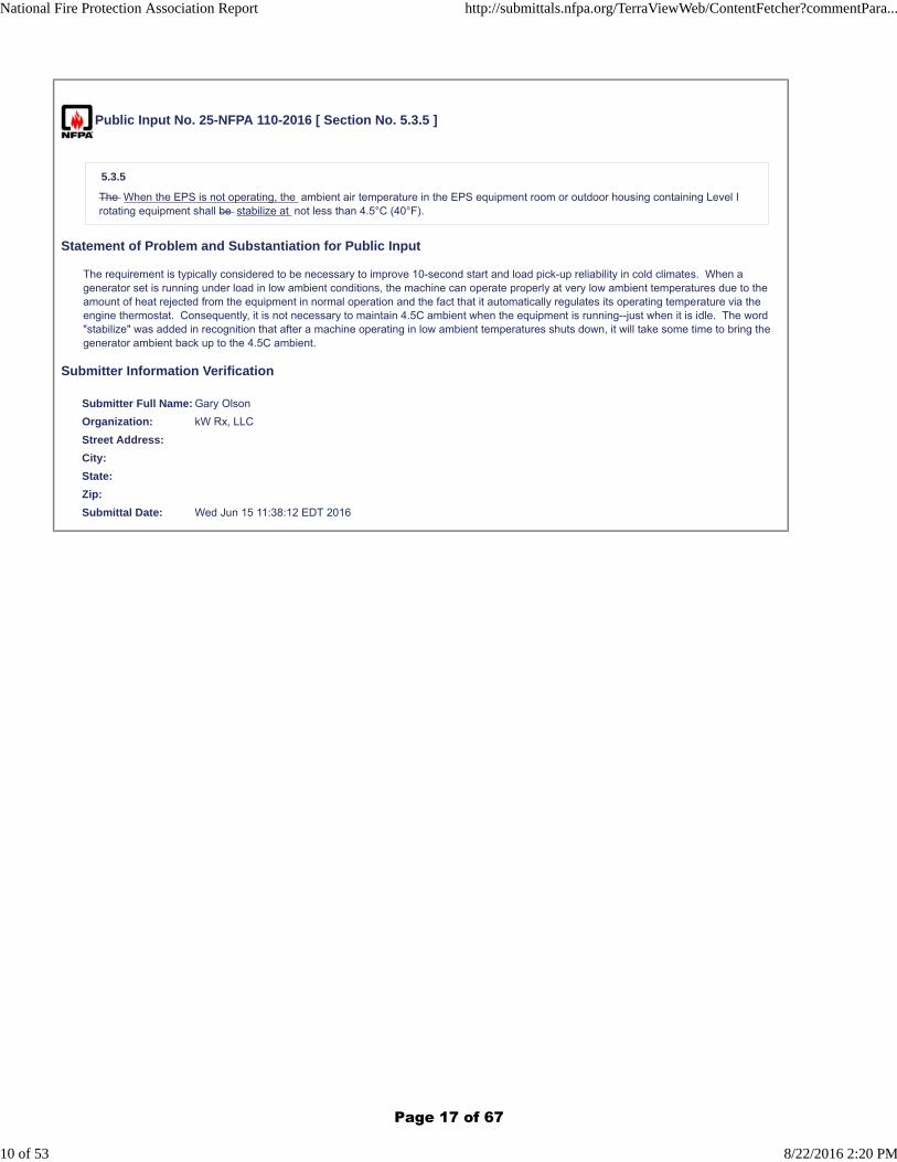
5.3.5
The When the EPS is not operating, the ambient air temperature in the EPS equipment room or outdoor housing containing Level Irotating equipment shall be stabilize at not less than 4.5°C (40°F).
Statement of Problem and Substantiation for Public Input
The requirement is typically considered to be necessary to improve 10-second start and load pick-up reliability in cold climates. When a generator set is running under load in low ambient conditions, the machine can operate properly at very low ambient temperatures due to the amount of heat rejected from the equipment in normal operation and the fact that it automatically regulates its operating temperature via the engine thermostat. Consequently, it is not necessary to maintain 4.5C ambient when the equipment is running--just when it is idle. The word "stabilize" was added in recognition that after a machine operating in low ambient temperatures shuts down, it will take some time to bring the generator ambient back up to the 4.5C ambient.
Submitter Information Verification
Submitter Full Name: Gary Olson
Organization: kW Rx, LLC
Street Address:
City:
State:
Zip:
Submittal Date: Wed Jun 15 11:38:12 EDT 2016
National Fire Protection Association Report http://submittals.nfpa.org/TerraViewWeb/ContentFetcher?commentPara...
10 of 53 8/22/2016 2:20 PM
Page 17 of 67
Public Input No. 45-NFPA 110-2016 [ Section No. 5.3.5 ]
5.3.5
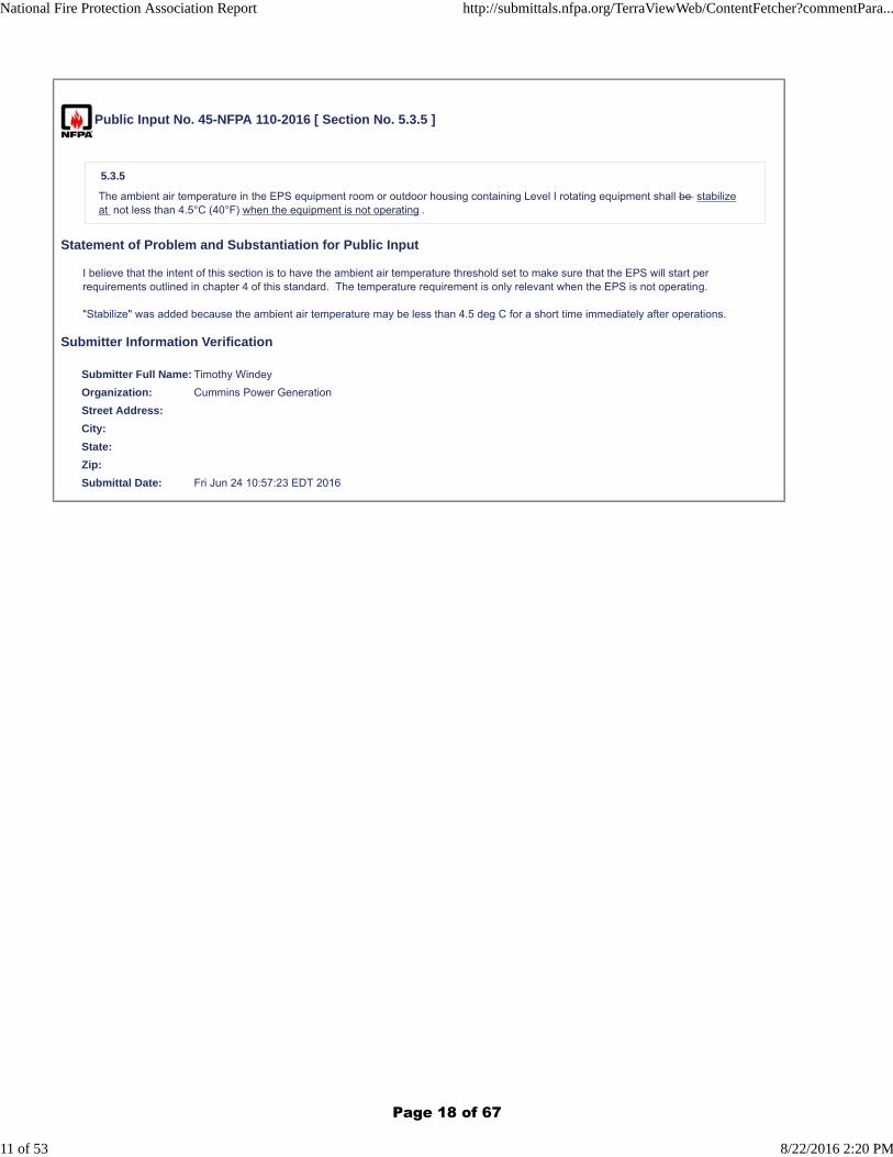
The ambient air temperature in the EPS equipment room or outdoor housing containing Level I rotating equipment shall be stabilizeat not less than 4.5°C (40°F) when the equipment is not operating .
Statement of Problem and Substantiation for Public Input
I believe that the intent of this section is to have the ambient air temperature threshold set to make sure that the EPS will start per requirements outlined in chapter 4 of this standard. The temperature requirement is only relevant when the EPS is not operating.
"Stabilize" was added because the ambient air temperature may be less than 4.5 deg C for a short time immediately after operations.
Submitter Information Verification
Submitter Full Name: Timothy Windey
Organization: Cummins Power Generation
Street Address:
City:
State:
Zip:
Submittal Date: Fri Jun 24 10:57:23 EDT 2016
National Fire Protection Association Report http://submittals.nfpa.org/TerraViewWeb/ContentFetcher?commentPara...
11 of 53 8/22/2016 2:20 PM
Page 18 of 67
Public Input No. 61-NFPA 110-2016 [ Section No. 5.4 ]
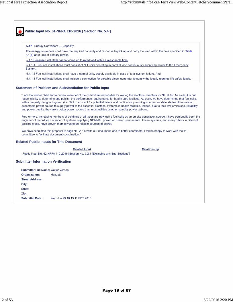
5.4* Energy Converters — Capacity.
The energy converters shall have the required capacity and response to pick up and carry the load within the time specified in Table4.1(b) after loss of primary power.
5.4.1 Because Fuel Cells cannot come up to rated load within a reasonable time,
5.4.1.1. Fuel cell installations must consist of N 1 units operating in parallel, and continuously supplying power to the EmergencySystem.
5.4.1.2 Fuel cell installations shall have a normal utility supply available in case of total system failure. And
5.4.1.3 Fuel cell installations shall include a connection for portable diesel generator to supply the legally required life safety loads.
Statement of Problem and Substantiation for Public Input
“I am the former chair and a current member of the committee responsible for writing the electrical chapters for NFPA 99. As such, it is our responsibility to determine and publish the performance requirements for health care facilities. As such, we have determined that fuel cells, with a properly designed system (i.e. N+1 to account for potential failure and continuously running to accommodate start-up time) are an acceptable power source to supply power to the essential electrical systems in health facilities. Indeed, due to their low emissions, reliability, and power quality, they are a better power source than most utilities or other standby power options.
Furthermore, increasing numbers of buildings of all types are now using fuel cells as an on-site generation source. I have personally been the engineer of record for a number of systems supplying NORMAL power for Kaiser Permanente. These systems, and many others in different building types, have proven themselves to be reliable sources of power.
We have submitted this proposal to align NFPA 110 with our document, and to better coordinate. I will be happy to work with the 110 committee to facilitate document coordination.”
Related Public Inputs for This Document
Related Input Relationship
Public Input No. 62-NFPA 110-2016 [Section No. 5.2.1 [Excluding any Sub-Sections]]
Submitter Information Verification
Submitter Full Name: Walter Vernon
Organization: Mazzetti
Street Address:
City:
State:
Zip:
Submittal Date: Wed Jun 29 16:13:11 EDT 2016
National Fire Protection Association Report http://submittals.nfpa.org/TerraViewWeb/ContentFetcher?commentPara...
12 of 53 8/22/2016 2:20 PM
Page 19 of 67
Public Input No. 19-NFPA 110-2016 [ Section No. 5.5.3 ]
5.5.3 *
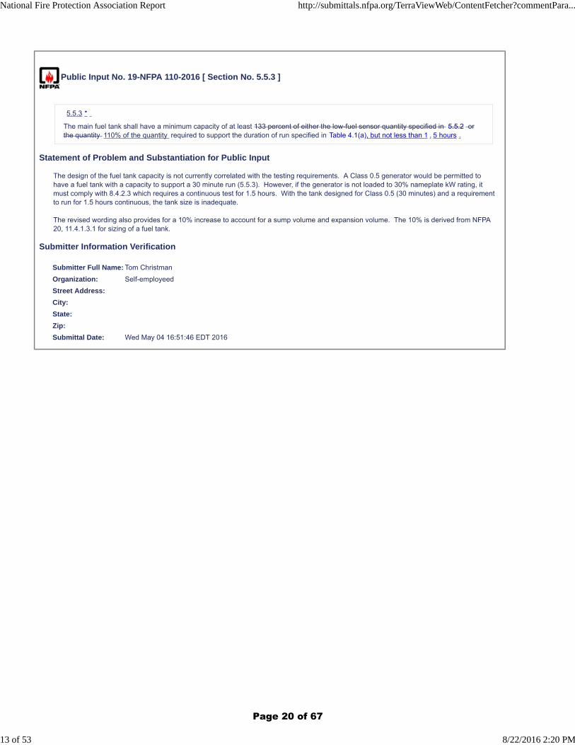
The main fuel tank shall have a minimum capacity of at least 133 percent of either the low-fuel sensor quantity specified in 5.5.2 orthe quantity 110% of the quantity required to support the duration of run specified in Table 4.1(a), but not less than 1 . 5 hours .
Statement of Problem and Substantiation for Public Input
The design of the fuel tank capacity is not currently correlated with the testing requirements. A Class 0.5 generator would be permitted to have a fuel tank with a capacity to support a 30 minute run (5.5.3). However, if the generator is not loaded to 30% nameplate kW rating, it must comply with 8.4.2.3 which requires a continuous test for 1.5 hours. With the tank designed for Class 0.5 (30 minutes) and a requirement to run for 1.5 hours continuous, the tank size is inadequate.
The revised wording also provides for a 10% increase to account for a sump volume and expansion volume. The 10% is derived from NFPA 20, 11.4.1.3.1 for sizing of a fuel tank.
Submitter Information Verification
Submitter Full Name: Tom Christman
Organization: Self-employeed
Street Address:
City:
State:
Zip:
Submittal Date: Wed May 04 16:51:46 EDT 2016
National Fire Protection Association Report http://submittals.nfpa.org/TerraViewWeb/ContentFetcher?commentPara...
13 of 53 8/22/2016 2:20 PM
Page 20 of 67
Public Input No. 43-NFPA 110-2016 [ Section No. 5.6.2 ]
5.6.2 Prime Mover Ratings.
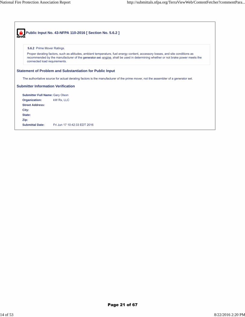
Proper derating factors, such as altitudes, ambient temperature, fuel energy content, accessory losses, and site conditions asrecommended by the manufacturer of the generator set engine shall be used in determining whether or not brake power meets theconnected load requirements.
Statement of Problem and Substantiation for Public Input
The authoritative source for actual derating factors is the manufacturer of the prime mover, not the assembler of a generator set.
Submitter Information Verification
Submitter Full Name: Gary Olson
Organization: kW Rx, LLC
Street Address:
City:
State:
Zip:
Submittal Date: Fri Jun 17 10:42:33 EDT 2016
National Fire Protection Association Report http://submittals.nfpa.org/TerraViewWeb/ContentFetcher?commentPara...
14 of 53 8/22/2016 2:20 PM
Page 21 of 67
Public Input No. 26-NFPA 110-2016 [ Section No. 5.6.3.6.1 ]
5.6.3.6.1
A battery charger driven by the prime mover shall not be required for Level 2 generators , provided the automatic battery charger hasa high-low rate capable of fully charging the starting battery during running conditions as specified in 5.6.3.6 . within the time framerequired by this standard while powering all loads connected to the starting batteries.
Statement of Problem and Substantiation for Public Input
An AC powered battery charger is less reliable than a mechanically driven DC alternator because the AC-powered system has several single points of failure including the incremental wiring, ac protective devices, and the charger itself. So, for critical applications it is reasonable to require both DC power sources in the system.
Generators often have significant DC loads when they are operating, in addition to the starting battery recharge duty. This addition makes it clear that the charger for critical applications must be capable of continuous operation with all loads attached.
Submitter Information Verification
Submitter Full Name: Gary Olson
Organization: kW Rx, LLC
Street Address:
City:
State:
Zip:
Submittal Date: Wed Jun 15 11:49:05 EDT 2016
National Fire Protection Association Report http://submittals.nfpa.org/TerraViewWeb/ContentFetcher?commentPara...
15 of 53 8/22/2016 2:20 PM
Page 22 of 67
Public Input No. 50-NFPA 110-2016 [ Section No. 5.6.4.2 [Excluding any Sub-Sections] ]
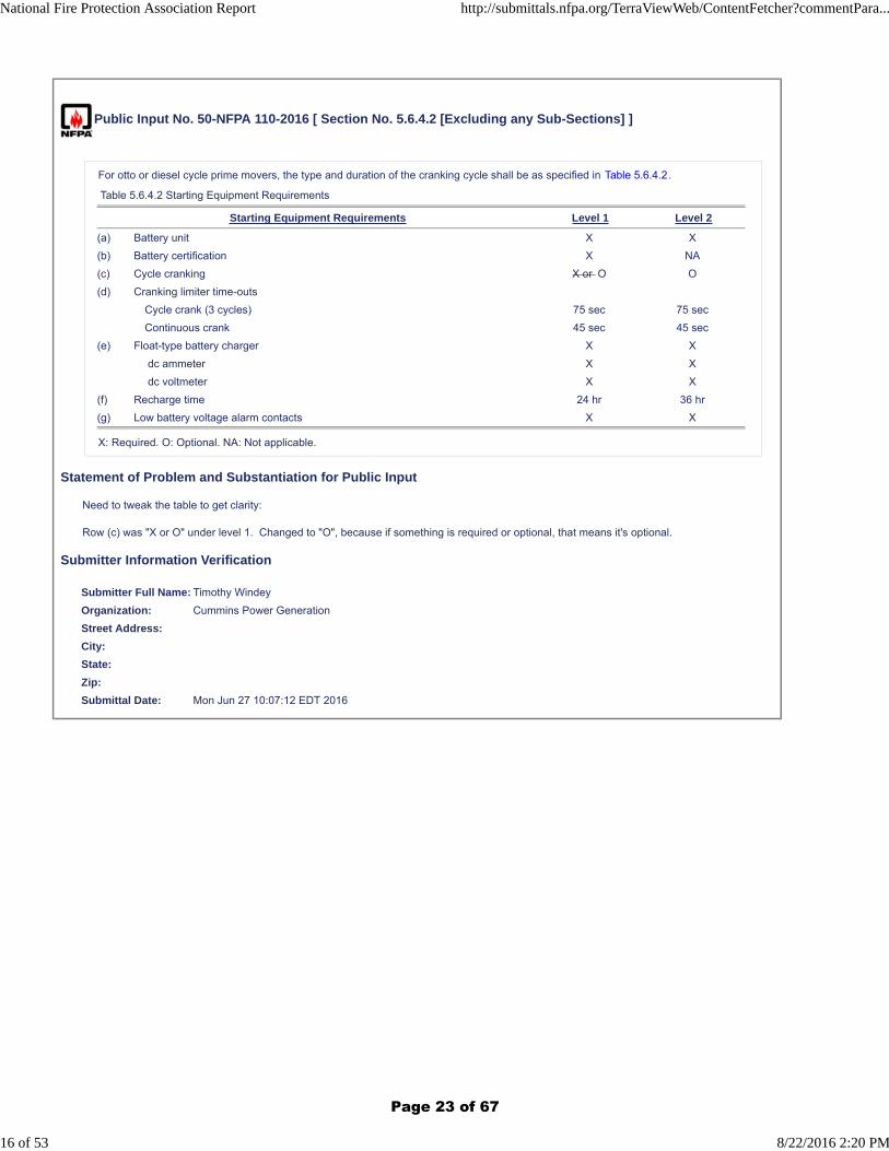
For otto or diesel cycle prime movers, the type and duration of the cranking cycle shall be as specified in Table 5.6.4.2.
Table 5.6.4.2 Starting Equipment Requirements
Starting Equipment Requirements Level 1 Level 2
(a) Battery unit X X
(b) Battery certification X NA
(c) Cycle cranking X or O O
(d) Cranking limiter time-outs
Cycle crank (3 cycles) 75 sec 75 sec
Continuous crank 45 sec 45 sec
(e) Float-type battery charger X X
dc ammeter X X
dc voltmeter X X
(f) Recharge time 24 hr 36 hr
(g) Low battery voltage alarm contacts X X
X: Required. O: Optional. NA: Not applicable.
Statement of Problem and Substantiation for Public Input
Need to tweak the table to get clarity:
Row (c) was "X or O" under level 1. Changed to "O", because if something is required or optional, that means it's optional.
Submitter Information Verification
Submitter Full Name: Timothy Windey
Organization: Cummins Power Generation
Street Address:
City:
State:
Zip:
Submittal Date: Mon Jun 27 10:07:12 EDT 2016
National Fire Protection Association Report http://submittals.nfpa.org/TerraViewWeb/ContentFetcher?commentPara...
16 of 53 8/22/2016 2:20 PM
Page 23 of 67
Public Input No. 27-NFPA 110-2016 [ Section No. 5.6.4.7 ]
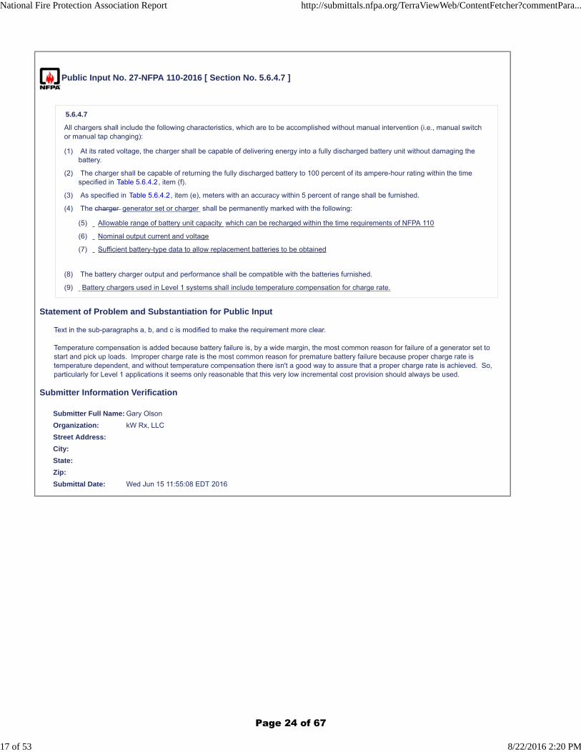
5.6.4.7
All chargers shall include the following characteristics, which are to be accomplished without manual intervention (i.e., manual switchor manual tap changing):
(1) At its rated voltage, the charger shall be capable of delivering energy into a fully discharged battery unit without damaging thebattery.
(2) The charger shall be capable of returning the fully discharged battery to 100 percent of its ampere-hour rating within the timespecified in Table 5.6.4.2, item (f).
(3) As specified in Table 5.6.4.2, item (e), meters with an accuracy within 5 percent of range shall be furnished.
(4) The charger generator set or charger shall be permanently marked with the following:
(5) Allowable range of battery unit capacity which can be recharged within the time requirements of NFPA 110
(6) Nominal output current and voltage
(7) Sufficient battery-type data to allow replacement batteries to be obtained
(8) The battery charger output and performance shall be compatible with the batteries furnished.
(9) Battery chargers used in Level 1 systems shall include temperature compensation for charge rate.
Statement of Problem and Substantiation for Public Input
Text in the sub-paragraphs a, b, and c is modified to make the requirement more clear.
Temperature compensation is added because battery failure is, by a wide margin, the most common reason for failure of a generator set to start and pick up loads. Improper charge rate is the most common reason for premature battery failure because proper charge rate is temperature dependent, and without temperature compensation there isn't a good way to assure that a proper charge rate is achieved. So, particularly for Level 1 applications it seems only reasonable that this very low incremental cost provision should always be used.
Submitter Information Verification
Submitter Full Name: Gary Olson
Organization: kW Rx, LLC
Street Address:
City:
State:
Zip:
Submittal Date: Wed Jun 15 11:55:08 EDT 2016
National Fire Protection Association Report http://submittals.nfpa.org/TerraViewWeb/ContentFetcher?commentPara...
17 of 53 8/22/2016 2:20 PM
Page 24 of 67
Public Input No. 28-NFPA 110-2016 [ Section No. 5.6.5.1 ]
5.6.5.1
A control panel shall be provided and shall contain the following:
(1) Automatic remote start capability
(2) “Run-off-automatic” switch functions
(3) Shutdowns as required by 5.6.5.2 (3)
(4) Alarms as required by 5.6.5.2 (4)
(5) Controls as required by 5.6.5.2 (5)
Statement of Problem and Substantiation for Public Input
Different manufacturers have labeled these functions in slightly different ways, and it is not important how they are labeled, as long as they are provided. Further, the text as currently written could be taken to require a single switch, while there is no reason why the functions could not be provided by separate push-buttons, or other switching mechanisms. So, simply requiring functions rather than a specifically labeled switch is a reasonable change.
Submitter Information Verification
Submitter Full Name: Gary Olson
Organization: kW Rx, LLC
Street Address:
City:
State:
Zip:
Submittal Date: Wed Jun 15 12:00:26 EDT 2016
National Fire Protection Association Report http://submittals.nfpa.org/TerraViewWeb/ContentFetcher?commentPara...
18 of 53 8/22/2016 2:20 PM
Page 25 of 67
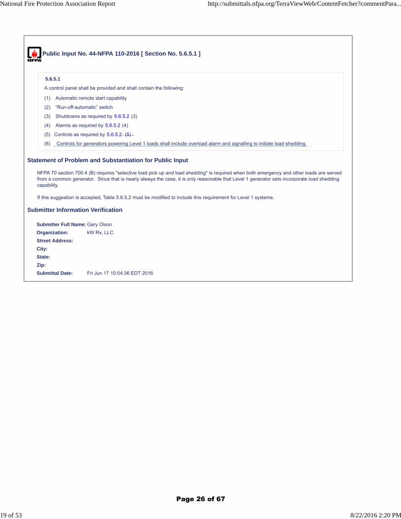
Public Input No. 44-NFPA 110-2016 [ Section No. 5.6.5.1 ]
5.6.5.1
A control panel shall be provided and shall contain the following:
(1) Automatic remote start capability
(2) “Run-off-automatic” switch
(3) Shutdowns as required by 5.6.5.2 (3)
(4) Alarms as required by 5.6.5.2 (4)
(5) Controls as required by 5.6.5.2 (5)
(6) Controls for generators powering Level 1 loads shall include overload alarm and signalling to initiate load shedding.
Statement of Problem and Substantiation for Public Input
NFPA 70 section 700.4 (B) requires "selective load pick up and load shedding" is required when both emergency and other loads are served from a common generator. Since that is nearly always the case, it is only reasonable that Level 1 generator sets incorporate load shedding capability.
If this suggestion is accepted, Table 5.6.5.2 must be modified to include this requirement for Level 1 systems.
Submitter Information Verification
Submitter Full Name: Gary Olson
Organization: kW Rx, LLC
Street Address:
City:
State:
Zip:
Submittal Date: Fri Jun 17 10:54:36 EDT 2016
National Fire Protection Association Report http://submittals.nfpa.org/TerraViewWeb/ContentFetcher?commentPara...
19 of 53 8/22/2016 2:20 PM
Page 26 of 67

Public Input No. 48-NFPA 110-2016 [ Section No. 5.6.5.2 ]
National Fire Protection Association Report http://submittals.nfpa.org/TerraViewWeb/ContentFetcher?commentPara...
20 of 53 8/22/2016 2:20 PM
Page 27 of 67

5.6.5.2
National Fire Protection Association Report http://submittals.nfpa.org/TerraViewWeb/ContentFetcher?commentPara...
21 of 53 8/22/2016 2:20 PM
Page 28 of 67
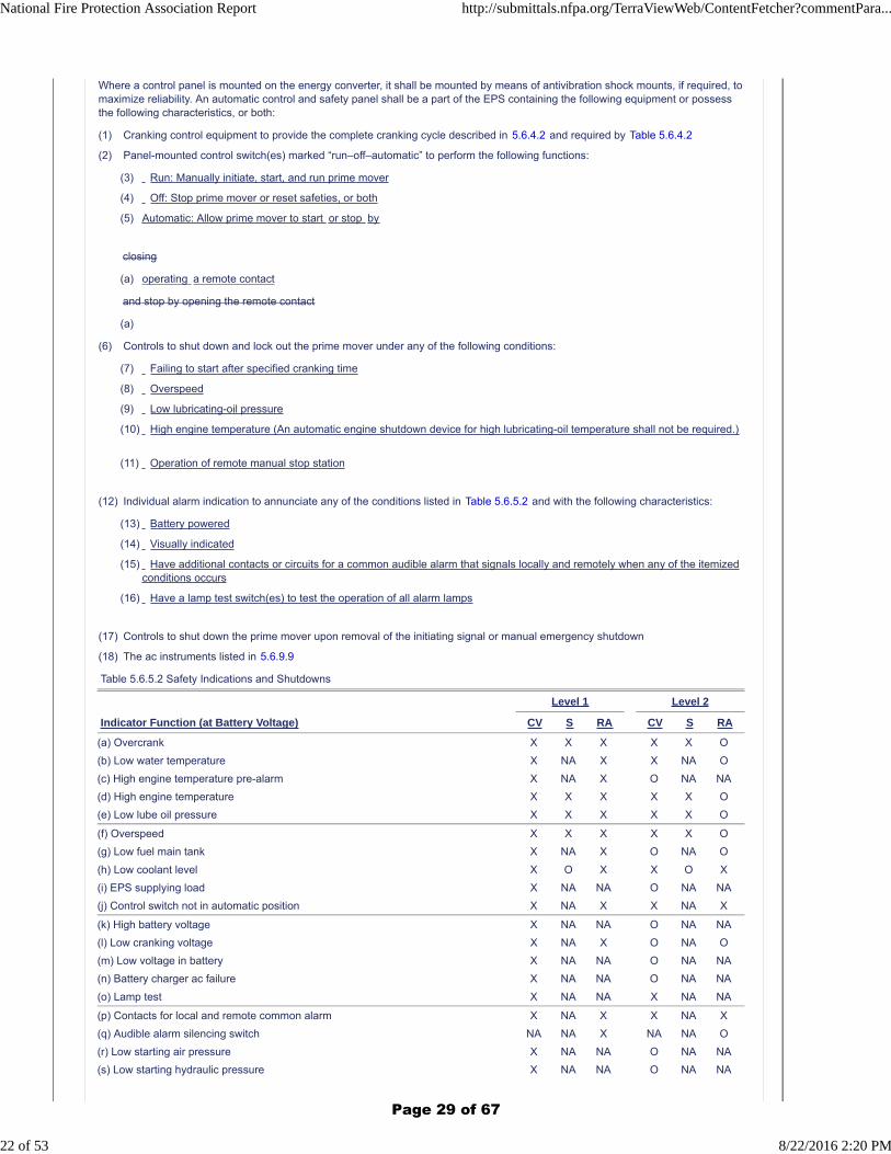
Where a control panel is mounted on the energy converter, it shall be mounted by means of antivibration shock mounts, if required, tomaximize reliability. An automatic control and safety panel shall be a part of the EPS containing the following equipment or possessthe following characteristics, or both:
(1) Cranking control equipment to provide the complete cranking cycle described in 5.6.4.2 and required by Table 5.6.4.2
(2) Panel-mounted control switch(es) marked “run–off–automatic” to perform the following functions:
(3) Run: Manually initiate, start, and run prime mover
(4) Off: Stop prime mover or reset safeties, or both
(5) Automatic: Allow prime mover to start or stop by
closing
(a) operating a remote contact
and stop by opening the remote contact
(a)
(6) Controls to shut down and lock out the prime mover under any of the following conditions:
(7) Failing to start after specified cranking time
(8) Overspeed
(9) Low lubricating-oil pressure
(10) High engine temperature (An automatic engine shutdown device for high lubricating-oil temperature shall not be required.)
(11) Operation of remote manual stop station
(12) Individual alarm indication to annunciate any of the conditions listed in Table 5.6.5.2 and with the following characteristics:
(13) Battery powered
(14) Visually indicated
(15) Have additional contacts or circuits for a common audible alarm that signals locally and remotely when any of the itemizedconditions occurs
(16) Have a lamp test switch(es) to test the operation of all alarm lamps
(17) Controls to shut down the prime mover upon removal of the initiating signal or manual emergency shutdown
(18) The ac instruments listed in 5.6.9.9
Table 5.6.5.2 Safety Indications and Shutdowns
Level 1 Level 2
Indicator Function (at Battery Voltage) CV S RA CV S RA
(a) Overcrank X X X X X O
(b) Low water temperature X NA X X NA O
(c) High engine temperature pre-alarm X NA X O NA NA
(d) High engine temperature X X X X X O
(e) Low lube oil pressure X X X X X O
(f) Overspeed X X X X X O
(g) Low fuel main tank X NA X O NA O
(h) Low coolant level X O X X O X
(i) EPS supplying load X NA NA O NA NA
(j) Control switch not in automatic position X NA X X NA X
(k) High battery voltage X NA NA O NA NA
(l) Low cranking voltage X NA X O NA O
(m) Low voltage in battery X NA NA O NA NA
(n) Battery charger ac failure X NA NA O NA NA
(o) Lamp test X NA NA X NA NA
(p) Contacts for local and remote common alarm X NA X X NA X
(q) Audible alarm silencing switch NA NA X NA NA O
(r) Low starting air pressure X NA NA O NA NA
(s) Low starting hydraulic pressure X NA NA O NA NA
National Fire Protection Association Report http://submittals.nfpa.org/TerraViewWeb/ContentFetcher?commentPara...
22 of 53 8/22/2016 2:20 PM
Page 29 of 67
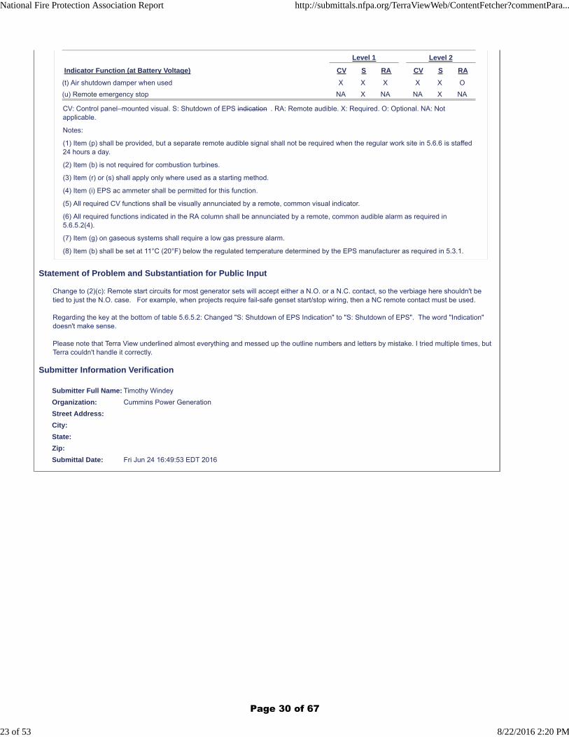
Level 1 Level 2
Indicator Function (at Battery Voltage) CV S RA CV S RA
(t) Air shutdown damper when used X X X X X O
(u) Remote emergency stop NA X NA NA X NA
CV: Control panel–mounted visual. S: Shutdown of EPS indication . RA: Remote audible. X: Required. O: Optional. NA: Notapplicable.
Notes:
(1) Item (p) shall be provided, but a separate remote audible signal shall not be required when the regular work site in 5.6.6 is staffed24 hours a day.
(2) Item (b) is not required for combustion turbines.
(3) Item (r) or (s) shall apply only where used as a starting method.
(4) Item (i) EPS ac ammeter shall be permitted for this function.
(5) All required CV functions shall be visually annunciated by a remote, common visual indicator.
(6) All required functions indicated in the RA column shall be annunciated by a remote, common audible alarm as required in5.6.5.2(4).
(7) Item (g) on gaseous systems shall require a low gas pressure alarm.
(8) Item (b) shall be set at 11°C (20°F) below the regulated temperature determined by the EPS manufacturer as required in 5.3.1.
Statement of Problem and Substantiation for Public Input
Change to (2)(c): Remote start circuits for most generator sets will accept either a N.O. or a N.C. contact, so the verbiage here shouldn't be tied to just the N.O. case. For example, when projects require fail-safe genset start/stop wiring, then a NC remote contact must be used.
Regarding the key at the bottom of table 5.6.5.2: Changed "S: Shutdown of EPS Indication" to "S: Shutdown of EPS". The word "Indication" doesn't make sense.
Please note that Terra View underlined almost everything and messed up the outline numbers and letters by mistake. I tried multiple times, but Terra couldn't handle it correctly.
Submitter Information Verification
Submitter Full Name: Timothy Windey
Organization: Cummins Power Generation
Street Address:
City:
State:
Zip:
Submittal Date: Fri Jun 24 16:49:53 EDT 2016
National Fire Protection Association Report http://submittals.nfpa.org/TerraViewWeb/ContentFetcher?commentPara...
23 of 53 8/22/2016 2:20 PM
Page 30 of 67
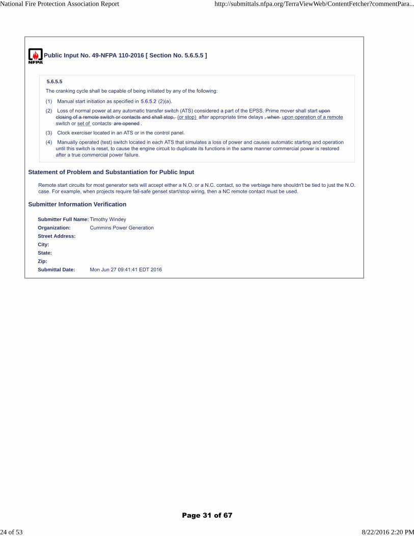
Public Input No. 49-NFPA 110-2016 [ Section No. 5.6.5.5 ]
5.6.5.5
The cranking cycle shall be capable of being initiated by any of the following:
(1) Manual start initiation as specified in 5.6.5.2 (2)(a).
(2) Loss of normal power at any automatic transfer switch (ATS) considered a part of the EPSS. Prime mover shall start uponclosing of a remote switch or contacts and shall stop, (or stop) after appropriate time delays , when upon operation of a remoteswitch or set of contacts are opened .
(3) Clock exerciser located in an ATS or in the control panel.
(4) Manually operated (test) switch located in each ATS that simulates a loss of power and causes automatic starting and operationuntil this switch is reset, to cause the engine circuit to duplicate its functions in the same manner commercial power is restoredafter a true commercial power failure.
Statement of Problem and Substantiation for Public Input
Remote start circuits for most generator sets will accept either a N.O. or a N.C. contact, so the verbiage here shouldn't be tied to just the N.O. case. For example, when projects require fail-safe genset start/stop wiring, then a NC remote contact must be used.
Submitter Information Verification
Submitter Full Name: Timothy Windey
Organization: Cummins Power Generation
Street Address:
City:
State:
Zip:
Submittal Date: Mon Jun 27 09:41:41 EDT 2016
National Fire Protection Association Report http://submittals.nfpa.org/TerraViewWeb/ContentFetcher?commentPara...
24 of 53 8/22/2016 2:20 PM
Page 31 of 67
Public Input No. 29-NFPA 110-2016 [ Section No. 5.6.9.9 ]
5.6.9.9
The generator instrument panel for Level 1 applications shall contain the following:
(1) An ac voltmeter(s) for each phase or a phase selector switch
(2) An ac ammeter(s) for each phase or a phase selector switch
(3) A frequency meter
(4) A voltage-adjusting feature to allow ± 5 percent voltage adjustment
(5) An ac kW meter indicating total load on the generator set
Statement of Problem and Substantiation for Public Input
In a generator set application an engine has very limited overload capability, and without a kW meter there is no easy way for an operator to visually see when loads are approaching the limits of the engine. (Because ammeters don't consider power factor, they don't actually indicate impending overload on an engine.)
Historically, kW meters were an expensive feature to add to a generator set, but now are a standard feature in most generator set products used in Level 1 systems.
Consequently, Level 1 systems should have this critical feature.
Submitter Information Verification
Submitter Full Name: Gary Olson
Organization: kW Rx, LLC
Street Address:
City:
State:
Zip:
Submittal Date: Wed Jun 15 12:12:39 EDT 2016
National Fire Protection Association Report http://submittals.nfpa.org/TerraViewWeb/ContentFetcher?commentPara...
25 of 53 8/22/2016 2:20 PM
Page 32 of 67
Public Input No. 33-NFPA 110-2016 [ Section No. 5.6.10.6 ]
5.6.10.6
Where requested, the short circuit current capability at the generator output terminals shall be furnished.
5.6.10.7 The energy converter for Level 1 systems shall be tested at the location of final assembly to demonstrate full load carryingcapability and transient performance under varying load levels. A test report documenting this performance shall be provided onrequest.
Statement of Problem and Substantiation for Public Input
The on-site testing of a generator set is thoroughly covered by NFPA 110, but the expected performance for a specific machine under controlled conditions is not required. Adding a requirement for factory testing provides an assurance that the generator set will carry load as required if installed correctly, and demonstrates expected transient performance prior to installation. Consequently, when the equipment is tested at site, there is a means to verify that it is properly installed using the factory test data as a means to verify that the site results are equal or better.
Submitter Information Verification
Submitter Full Name: Gary Olson
Organization: kW Rx, LLC
Street Address:
City:
State:
Zip:
Submittal Date: Wed Jun 15 12:57:46 EDT 2016
National Fire Protection Association Report http://submittals.nfpa.org/TerraViewWeb/ContentFetcher?commentPara...
26 of 53 8/22/2016 2:20 PM
Page 33 of 67
Public Input No. 36-NFPA 110-2016 [ Section No. 6.1.2 ]
6.1.2*
The electrical rating ratings of the transfer switch shall be sized for selected based on the total load that is designed to beconnected, and the available fault current .
Statement of Problem and Substantiation for Public Input
Currently there are no requirements in section 6.1 that are directed toward proper selection of a transfer switch in terms of both steady state ratings and fault current capability. Sections 6.3.1 & 2 add requirements, but they appear only as requirements for paralleling applications.
The text in 6.3.1 and 6.3.1 is in error, because listed transfer switches do not have interrupting ratings. Listed transfer switches have withstand&closing ratings, and steady state ratings. All listed transfer switches are continuously rated at their nameplate current rating.
This change suggests moving the rating requirements so that they clearly apply to all transfer switches, and correcting them to include proper wording for the actual requirements.
Submitter Information Verification
Submitter Full Name: Gary Olson
Organization: kW Rx, LLC
Street Address:
City:
State:
Zip:
Submittal Date: Thu Jun 16 11:27:33 EDT 2016
National Fire Protection Association Report http://submittals.nfpa.org/TerraViewWeb/ContentFetcher?commentPara...
27 of 53 8/22/2016 2:20 PM
Page 34 of 67
Public Input No. 3-NFPA 110-2016 [ Section No. 6.2.2.1 ]
6.2.2.1 *
Undervoltage-sensing devices shall be provided to monitor all ungrounded lines of the primary the normal source of power asfollows:
(1) When the voltage on any phase falls below the minimum operating voltage of any load to be served, the transfer switch shallautomatically initiate engine start and the process of transfer to the EPS.
(2)
Additional Proposed Changes
File Name Description Approved
NFPA_110_Public_Input_submission.docx
Statement of Problem and Substantiation for Public Input
The word "primary" used to describe the power source referenced in this paragraph is not consistent with other NFPA documents. NFPA70 and 99 both use "normal" to describe this power source in multiple places. The word "normal" is also the conventional term used in the electrical power industry and by most equipment manufacturers on their products and literature describing this power source and the transfer switch position. The word "primary" is also used in paragraphs 6.2.3, 6.2.8, 6.2.9.1, 6.2.9.2, 6.2.11.1, 6.2.12 and 6.2.16.1 and should be to "normal" for consistency.
Submitter Information Verification
Submitter Full Name: Ronald Schroeder
Organization: ASCO Power Technologies, LP
Street Address:
City:
State:
Zip:
Submittal Date: Wed Jan 13 11:13:58 EST 2016
* When the voltage on all phases of the primary the normal source returns to within specified limits for a designated period oftime, the process of transfer back to primary to normal power shall be initiated.
National Fire Protection Association Report http://submittals.nfpa.org/TerraViewWeb/ContentFetcher?commentPara...
28 of 53 8/22/2016 2:20 PM
Page 35 of 67

NFPA 110 Public Input submission
The word "primary" used to describe the power source referenced in this paragraph is not consistent
with other NFPA documents. NFPA70 and 99 both use "normal" to describe this power source in
multiple places. The word "normal" is also the conventional term used in the electrical power industry
and by most equipment manufacturers on their products and literature describing this power source
and the transfer switch position. The word "primary" is also used in paragraphs 6.2.3, 6.2.8, 6.2.9.1,
6.2.9.2, 6.2.11.1, 6.2.12 and 6.2.16.1 and should be to "normal" for consistency.
Page 36 of 67
Public Input No. 54-NFPA 110-2016 [ Section No. 6.2.5 ]
6.2.5* Time Delay on Starting of EPS.
A time-delay device shall be provided to delay starting of the EPS. The timer shall prevent nuisance starting of the EPS and possiblesubsequent load transfer in the event of harmless momentary power dips and interruptions of the primary source.
Statement of Problem and Substantiation for Public Input
Need to remove the word "harmless" from the sentence. If there are momentary power dips and interruptions with the primary source, we don't really know if they will be harmless. It could be harmless to some loads, but not harmless to others.
Submitter Information Verification
Submitter Full Name: Timothy Windey
Organization: Cummins Power Generation
Street Address:
City:
State:
Zip:
Submittal Date: Tue Jun 28 16:05:24 EDT 2016
National Fire Protection Association Report http://submittals.nfpa.org/TerraViewWeb/ContentFetcher?commentPara...
29 of 53 8/22/2016 2:20 PM
Page 37 of 67
Public Input No. 47-NFPA 110-2016 [ Section No. 6.3 ]
6.3 Load Switching (Load Shedding) Requirements for Paralleled Generator Sets .
When two or more engine generator sets are paralleled for emergency power, the paralleled system is the source, and system logicshall be arranged to inhibit connection of EPS-damaging manage the loads.
6.3.1
Each transfer switch shall have a continuous current rating and interrupting rating for all classes of loads to be served.
6.3.2
The transfer switch shall be capable of withstanding the available fault current at the point of installation.
6.3.3
The transfer of loads to the EPS shall be sequenced as follows:
(1) First-priority loads shall be switched to the emergency bus upon sensing the availability of emergency power on the bus.
(2) Each time an additional engine generator set is connected to the bus, a remaining load shall be connected in order of priorityuntil all emergency loads are connected to the bus.
(3) The system shall be designed so that, upon failure of one or more engine generator sets, the load is automatically reduced,starting with the load of least priority and proceeding in ascending priority, so that the last load affected is the highest-priority load.
Statement of Problem and Substantiation for Public Input
The title "Load Switching (Load Shedding)" is too specific for this section, and only describes what's going on in 6.3.3.(3). Section 6.3 and the underlying text are really about the requirements for transfer switches used with paralleled generator sets, so we should call it that.
Also need to add clarity that the paralleled system is the source, so that ATS ratings can be correctly chosen. Final point of clarity is to change the last part of the sentence to make it clear that the system logic is managing the loads, whether it's priority pickup (when gensets are coming on line), or load shed (if a genset fails).
Submitter Information Verification
Submitter Full Name: Timothy Windey
Organization: Cummins Power Generation
Street Address:
City:
State:
Zip:
Submittal Date: Fri Jun 24 13:18:31 EDT 2016
National Fire Protection Association Report http://submittals.nfpa.org/TerraViewWeb/ContentFetcher?commentPara...
30 of 53 8/22/2016 2:20 PM
Page 38 of 67
Public Input No. 30-NFPA 110-2016 [ Section No. 6.3 [Excluding any Sub-Sections] ]
When two or more engine generator sets are paralleled for emergency power, the paralleled system shall be arranged to inhibitconnection of EPS non -damaging loads emergency loads until adequate capacity is available to operate all loads; and commandshedding of non-emergency loads when the system is overloaded .
Statement of Problem and Substantiation for Public Input
"EPS-damaging" is an undefined term; and in fact, an EPS may be unexpectedly caused to shut down, but will typically not be damaged by an overload. NEC requires that emergency loads and fire pump loads be served at the expense of non-emergency loads. So, this text change corrects the confusion that the undefined term might start and adds the requirement for both load control for addition of loads, and load shedding in compliance to NEC requirements.
Submitter Information Verification
Submitter Full Name: Gary Olson
Organization: kW Rx, LLC
Street Address:
City:
State:
Zip:
Submittal Date: Wed Jun 15 12:23:34 EDT 2016
National Fire Protection Association Report http://submittals.nfpa.org/TerraViewWeb/ContentFetcher?commentPara...
31 of 53 8/22/2016 2:20 PM
Page 39 of 67
Public Input No. 31-NFPA 110-2016 [ Sections 6.3.1, 6.3.2 ]
Sections 6.3.1, 6.3.2
6.3.1
Each transfer switch shall have a continuous current rating and interrupting rating for all classes of loads to be served.
6.3.2
The transfer switch shall be capable of withstanding the available fault current at the point of installation.
Statement of Problem and Substantiation for Public Input
Section 6.3 relates only to paralleling applications while these paragraphs logically apply to all transfer switches. Suggest that these paragraphs be added to section 6.1 and corrected to include proper wording for transfer switch steady state and short circuit ratings.
Submitter Information Verification
Submitter Full Name: Gary Olson
Organization: kW Rx, LLC
Street Address:
City:
State:
Zip:
Submittal Date: Wed Jun 15 12:30:26 EDT 2016
National Fire Protection Association Report http://submittals.nfpa.org/TerraViewWeb/ContentFetcher?commentPara...
32 of 53 8/22/2016 2:20 PM
Page 40 of 67
Public Input No. 64-NFPA 110-2016 [ Section No. 7.3 ]
7.3 Lighting.
7.3.1
The Level 1 or Level 2 EPS equipment location(s) shall be provided with battery-powered emergency lighting. This requirement shallnot apply to units located outdoors in enclosures that do not include walk-in access.
7.3.2
The emergency lighting charging system and the normal service room lighting shall be supplied from the load side of the transferswitch.
7.3.3*
The minimum average horizontal illumination provided by normal lighting sources in the separate building or room housing the EPSequipment for Level 1 shall be 32.3 lux (3.0 ft-candles) measured at the floor level, unless otherwise specified by a requirementrecognized by the authority having jurisdiction.
7.4
The ingress path into the EPS room shall be illuminated at 32.3 lux (3.0 ft-candles).
Statement of Problem and Substantiation for Public Input
We want rescue personnel to have a safe path into the electrical service room. The ingress path is not always the same as the egress path.
Submitter Information Verification
Submitter Full Name: Michael Anthony
Organization: University of Michigan | Business & Finance Plant Operations | @StandardsUMich
Street Address:
City:
State:
Zip:
Submittal Date: Wed Jun 29 16:54:09 EDT 2016
National Fire Protection Association Report http://submittals.nfpa.org/TerraViewWeb/ContentFetcher?commentPara...
33 of 53 8/22/2016 2:20 PM
Page 41 of 67
Public Input No. 57-NFPA 110-2016 [ Section No. 7.9.13 ]
7.9.13
Automatically actuated valves shall not be permitted in the fuel oil supply or fuel oil return lines for Level 1 Emergency Power SupplySystems .
Statement of Problem and Substantiation for Public Input
Level 1 EPSS is defined in NFPA-110 Clause 4.4.1 as emergency engines that provide back-up power for systems where failure to perform can result in loss of human life or serious injury. These systems may include safety systems including fire pumps, emergency lighting, and elevators.
Level 2 EPSS is defined in NFPA-110 Clause 4.4.2 equipment specifically calls out stand-by power for applications where a failure is less critical to human life and safety and specifically includes communications systems described in the annex.
Information technology (IT), telecommunications, financial services, and enterprise customers routinely employ stand-by generators for equipment that has integral back-up batteries via UPS systems or stand-by batteries. These installations warrant protection from a continuing generator fire (if fuel continues to flow during a fire scenario). Since these generators are not providing life safety functions, the prevention of physical damage to network or IT infrastructure from fire is more critical in these installations.
Secondly, the definition of automatically actuated valves is not defined. Valves that utilize fusible links (thermally activate) that activate only during the physical temperature extreme associated with fire are a reliable, passive, device that “automatically” actuates valves. These safety measures are warranted for NFPA Level 2 EPSS. The principle or automatic activation is similar to automatic sprinkler systems (which are life safety) that utilize fusible link activation.
Finally, both NFPA-30, Flammable and Combustible Liquid Code, 2015, and NFPA-37, Standard for the Installation and Use of Stationary Combustion Engines, 2016, have no prohibition on automatically activated valves on fuel lines and describe use of these valves in the NFPA-37 Appendix A. Fuel piping clause 6.8.3 states “Valves shall be provided to control the flow of liquid fuel in normal operation and shut off fuel in the event of a pipe break”. Explanatory notes in Appendix A6.8.3 states, “manual valves located away from the engine or outside the engine room can be used as emergency shut-off devices. Solenoid valves interlocked with other controls also can be used to shut off the fuel supply. In the event of a fire, automatic valves utilizing fusible links have been used to shut off fuel supplies...” Similarly gas turbines are required to have automatically controlled valves as described in clause 6.8.3.1, “these valves shall operate automatically to stop the flow of fuel in the event the engine stops for any reason”.
NFPA-37 also refers to NFPA-30 Section 27 for fuel lines. Clause 27.6.6.1 states “piping systems shall contain valves to operate the system properly and to isolate equipment in the case of emergency." Furthermore clause 27.6.6.2 states; “piping systems in connection with pumps shall contain valves to properly control flow of liquid in both normal operation and in the event of an emergency”
Based on reliability of fusible links or other automatically actuated valves, NFPA 110 Level 2 generators that do not support life safety systems should be allowed to use automatically actuated valves to protect network or IT infrastructure from fire.
Submitter Information Verification
Submitter Full Name: Randy Schubert
Organization: Ericsson
Affilliation: ATIS (Alliance for Telecommunications Industry Solutions)
Street Address:
City:
State:
Zip:
Submittal Date: Tue Jun 28 18:25:44 EDT 2016
National Fire Protection Association Report http://submittals.nfpa.org/TerraViewWeb/ContentFetcher?commentPara...
34 of 53 8/22/2016 2:20 PM
Page 42 of 67
Public Input No. 46-NFPA 110-2016 [ Section No. 7.11.6 ]
7.11.6*
For systems in seismic risk areas, the EPS, transfer switches, distribution panels, circuit breakers, and associated controls shall becapable of performing their intended function during and after being subjected to the anticipated seismic shock.
Statement of Problem and Substantiation for Public Input
Need to align the seismic requirements in this document with the International Building Codes (IBC). The IBC requires that generator sets and their support equipment, transfer switches, and switchgear be able to operate after a seismic event.
Submitter Information Verification
Submitter Full Name: Timothy Windey
Organization: Cummins Power Generation
Street Address:
City:
State:
Zip:
Submittal Date: Fri Jun 24 11:43:22 EDT 2016
National Fire Protection Association Report http://submittals.nfpa.org/TerraViewWeb/ContentFetcher?commentPara...
35 of 53 8/22/2016 2:20 PM
Page 43 of 67
Public Input No. 32-NFPA 110-2016 [ Section No. 7.12.3 ]
7.12.3
The wiring between the EPS output terminals and the first distribution overcurrent protective device(s) terminals within the EPSSshall be located at a minimal distance as close as practical to ensure system reliability and safety.
FPN: NFPA 70 requires only overload protection for the generator (445.12), so the overcurrent protective device used for overloadprotection of a generator may be located at the generator or in a remote location where the balance of the distribution system isconnected.
Statement of Problem and Substantiation for Public Input
As written, this paragraph could be interpreted to conflict with NFPA 70 445.12, since it may be taken to imply that the required generator protection must be on the generator, which is not the intent of NFPA 70. Overload protection means that short circuit protection of the conductors from the generator terminals to the first downstream distribution device is not required. A fine print note would make it clear that it is desirable to have the generator located close to the loads that it serves, but this should not be confused with changing the protection requirements for the generator or conductors connecting the system loads.
Submitter Information Verification
Submitter Full Name: Gary Olson
Organization: kW Rx, LLC
Street Address:
City:
State:
Zip:
Submittal Date: Wed Jun 15 12:41:11 EDT 2016
National Fire Protection Association Report http://submittals.nfpa.org/TerraViewWeb/ContentFetcher?commentPara...
36 of 53 8/22/2016 2:20 PM
Page 44 of 67
Public Input No. 34-NFPA 110-2016 [ Section No. 7.13.4.3 [Excluding any Sub-Sections] ]
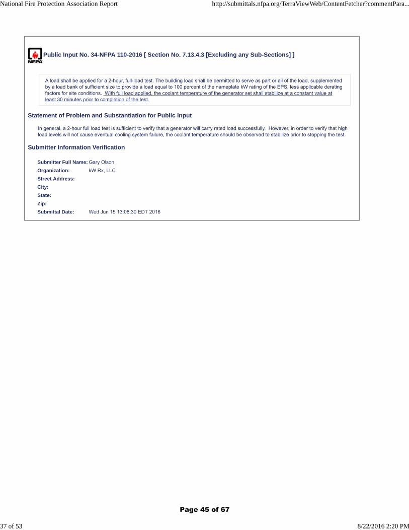
A load shall be applied for a 2-hour, full-load test. The building load shall be permitted to serve as part or all of the load, supplementedby a load bank of sufficient size to provide a load equal to 100 percent of the nameplate kW rating of the EPS, less applicable deratingfactors for site conditions. With full load applied, the coolant temperature of the generator set shall stabilize at a constant value atleast 30 minutes prior to completion of the test.
Statement of Problem and Substantiation for Public Input
In general, a 2-hour full load test is sufficient to verify that a generator will carry rated load successfully. However, in order to verify that high load levels will not cause eventual cooling system failure, the coolant temperature should be observed to stabilize prior to stopping the test.
Submitter Information Verification
Submitter Full Name: Gary Olson
Organization: kW Rx, LLC
Street Address:
City:
State:
Zip:
Submittal Date: Wed Jun 15 13:08:30 EDT 2016
National Fire Protection Association Report http://submittals.nfpa.org/TerraViewWeb/ContentFetcher?commentPara...
37 of 53 8/22/2016 2:20 PM
Page 45 of 67
Public Input No. 35-NFPA 110-2016 [ Section No. 7.13.4.5 ]
7.13.4.5
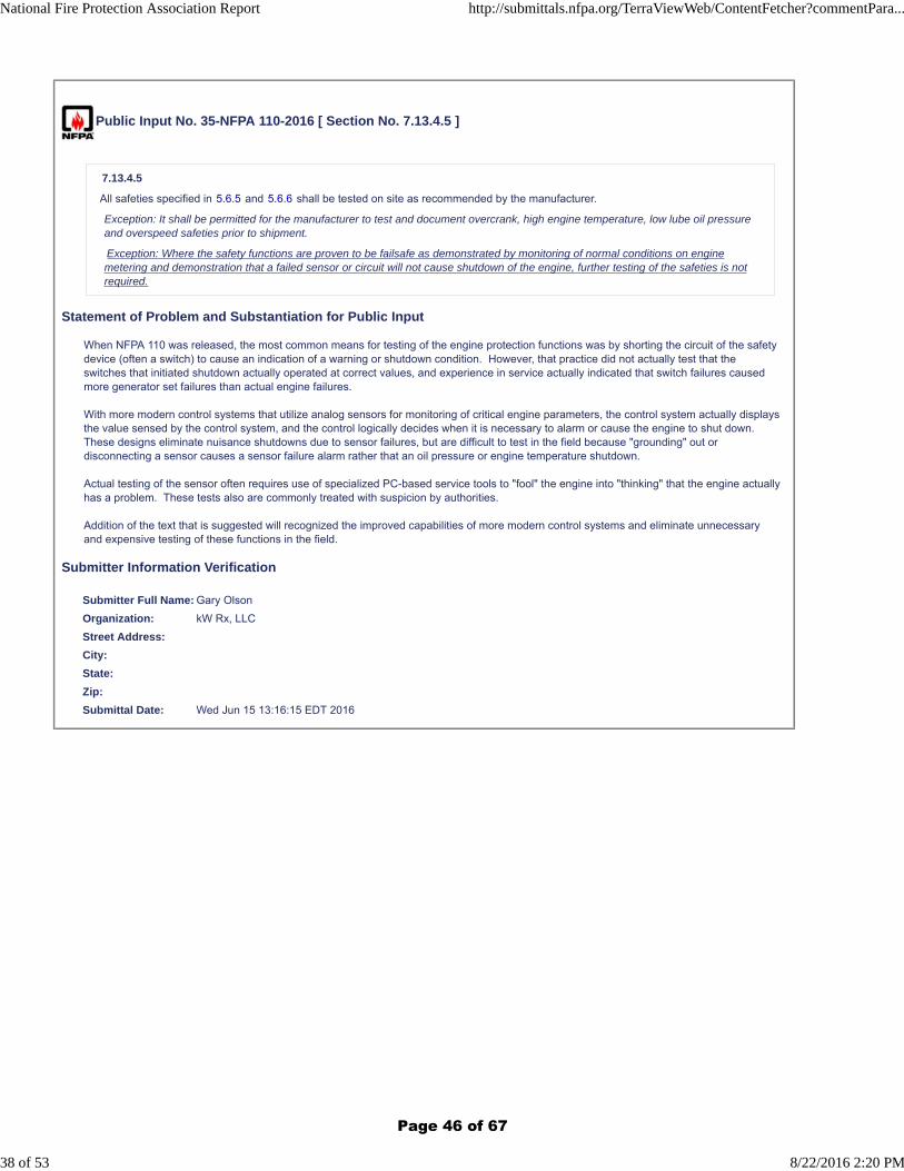
All safeties specified in 5.6.5 and 5.6.6 shall be tested on site as recommended by the manufacturer.
Exception: It shall be permitted for the manufacturer to test and document overcrank, high engine temperature, low lube oil pressureand overspeed safeties prior to shipment.
Exception: Where the safety functions are proven to be failsafe as demonstrated by monitoring of normal conditions on enginemetering and demonstration that a failed sensor or circuit will not cause shutdown of the engine, further testing of the safeties is notrequired.
Statement of Problem and Substantiation for Public Input
When NFPA 110 was released, the most common means for testing of the engine protection functions was by shorting the circuit of the safety device (often a switch) to cause an indication of a warning or shutdown condition. However, that practice did not actually test that the switches that initiated shutdown actually operated at correct values, and experience in service actually indicated that switch failures caused more generator set failures than actual engine failures.
With more modern control systems that utilize analog sensors for monitoring of critical engine parameters, the control system actually displays the value sensed by the control system, and the control logically decides when it is necessary to alarm or cause the engine to shut down. These designs eliminate nuisance shutdowns due to sensor failures, but are difficult to test in the field because "grounding" out or disconnecting a sensor causes a sensor failure alarm rather that an oil pressure or engine temperature shutdown.
Actual testing of the sensor often requires use of specialized PC-based service tools to "fool" the engine into "thinking" that the engine actually has a problem. These tests also are commonly treated with suspicion by authorities.
Addition of the text that is suggested will recognized the improved capabilities of more modern control systems and eliminate unnecessary and expensive testing of these functions in the field.
Submitter Information Verification
Submitter Full Name: Gary Olson
Organization: kW Rx, LLC
Street Address:
City:
State:
Zip:
Submittal Date: Wed Jun 15 13:16:15 EDT 2016
National Fire Protection Association Report http://submittals.nfpa.org/TerraViewWeb/ContentFetcher?commentPara...
38 of 53 8/22/2016 2:20 PM
Page 46 of 67
Public Input No. 37-NFPA 110-2016 [ Section No. 8.4.2 ]
8.4.2*
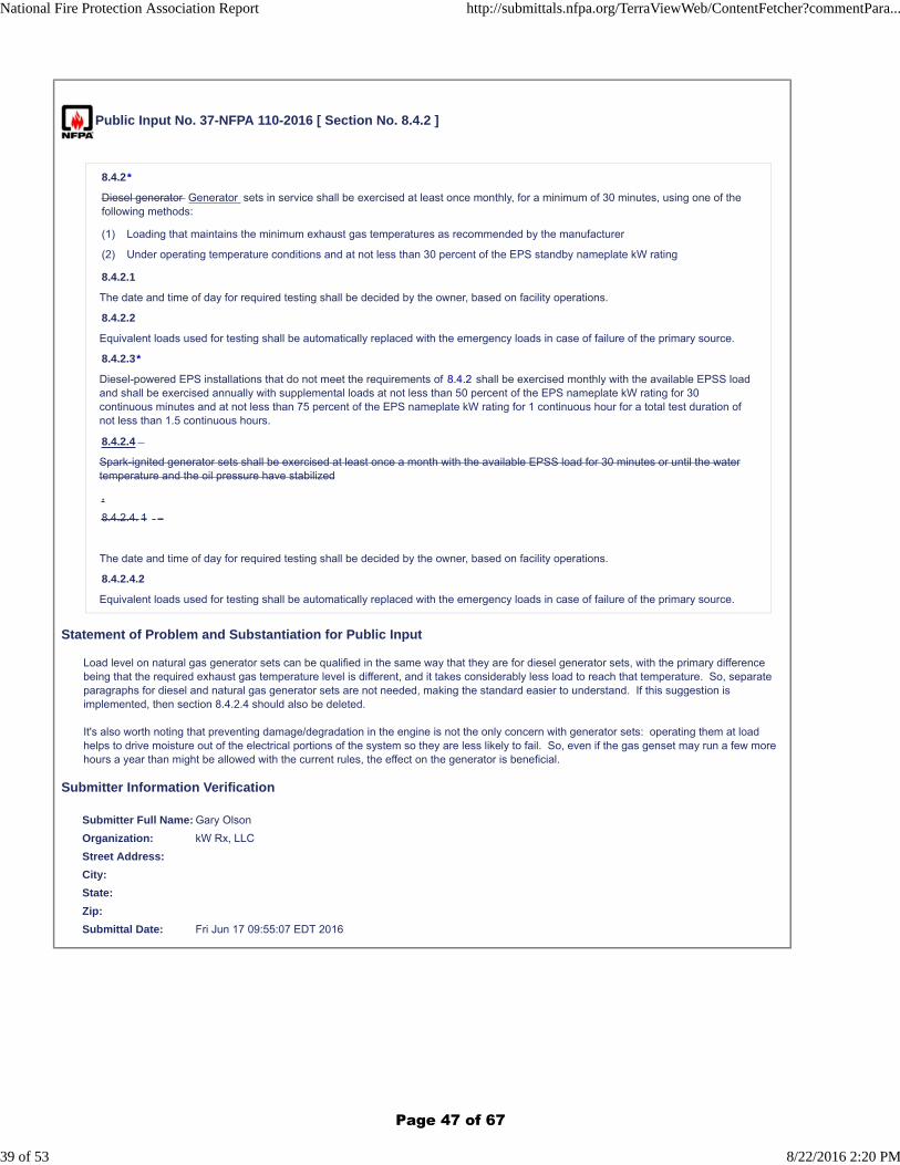
Diesel generator Generator sets in service shall be exercised at least once monthly, for a minimum of 30 minutes, using one of thefollowing methods:
(1) Loading that maintains the minimum exhaust gas temperatures as recommended by the manufacturer
(2) Under operating temperature conditions and at not less than 30 percent of the EPS standby nameplate kW rating
8.4.2.1
The date and time of day for required testing shall be decided by the owner, based on facility operations.
8.4.2.2
Equivalent loads used for testing shall be automatically replaced with the emergency loads in case of failure of the primary source.
8.4.2.3*
Diesel-powered EPS installations that do not meet the requirements of 8.4.2 shall be exercised monthly with the available EPSS loadand shall be exercised annually with supplemental loads at not less than 50 percent of the EPS nameplate kW rating for 30continuous minutes and at not less than 75 percent of the EPS nameplate kW rating for 1 continuous hour for a total test duration ofnot less than 1.5 continuous hours.
8.4.2.4
Spark-ignited generator sets shall be exercised at least once a month with the available EPSS load for 30 minutes or until the watertemperature and the oil pressure have stabilized
.
8.4.2.4. 1
The date and time of day for required testing shall be decided by the owner, based on facility operations.
8.4.2.4.2
Equivalent loads used for testing shall be automatically replaced with the emergency loads in case of failure of the primary source.
Statement of Problem and Substantiation for Public Input
Load level on natural gas generator sets can be qualified in the same way that they are for diesel generator sets, with the primary difference being that the required exhaust gas temperature level is different, and it takes considerably less load to reach that temperature. So, separate paragraphs for diesel and natural gas generator sets are not needed, making the standard easier to understand. If this suggestion is implemented, then section 8.4.2.4 should also be deleted.
It's also worth noting that preventing damage/degradation in the engine is not the only concern with generator sets: operating them at load helps to drive moisture out of the electrical portions of the system so they are less likely to fail. So, even if the gas genset may run a few more hours a year than might be allowed with the current rules, the effect on the generator is beneficial.
Submitter Information Verification
Submitter Full Name: Gary Olson
Organization: kW Rx, LLC
Street Address:
City:
State:
Zip:
Submittal Date: Fri Jun 17 09:55:07 EDT 2016
National Fire Protection Association Report http://submittals.nfpa.org/TerraViewWeb/ContentFetcher?commentPara...
39 of 53 8/22/2016 2:20 PM
Page 47 of 67
Public Input No. 1-NFPA 110-2015 [ Section No. 8.4.5 ]
8.4.5
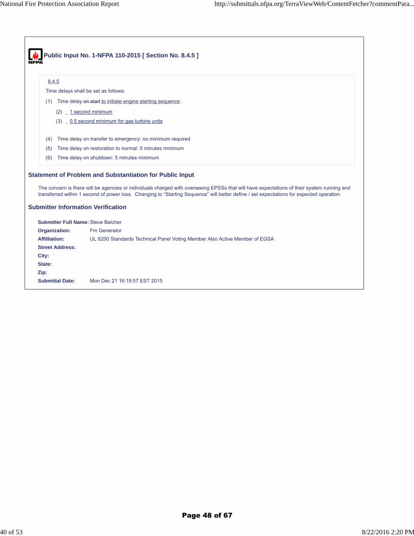
Time delays shall be set as follows:
(1) Time delay on start to initiate engine starting sequence :
(2) 1 second minimum
(3) 0.5 second minimum for gas turbine units
(4) Time delay on transfer to emergency: no minimum required
(5) Time delay on restoration to normal: 5 minutes minimum
(6) Time delay on shutdown: 5 minutes minimum
Statement of Problem and Substantiation for Public Input
The concern is there will be agencies or individuals charged with overseeing EPSSs that will have expectations of their system running and transferred within 1 second of power loss. Changing to “Starting Sequence” will better define / set expectations for expected operation.
Submitter Information Verification
Submitter Full Name: Steve Belcher
Organization: Fm Generator
Affilliation: UL 6200 Standards Technical Panel Voting Member Also Active Member of EGSA
Street Address:
City:
State:
Zip:
Submittal Date: Mon Dec 21 16:19:57 EST 2015
National Fire Protection Association Report http://submittals.nfpa.org/TerraViewWeb/ContentFetcher?commentPara...
40 of 53 8/22/2016 2:20 PM
Page 48 of 67
Public Input No. 15-NFPA 110-2016 [ Section No. 8.4.9.7 ]
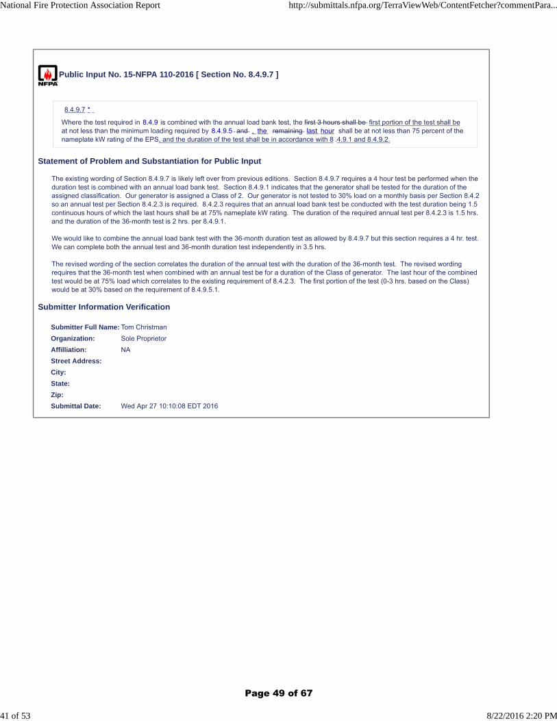
8.4.9.7 *
Where the test required in 8.4.9 is combined with the annual load bank test, the first 3 hours shall be first portion of the test shall beat not less than the minimum loading required by 8.4.9.5 and , the remaining last hour shall be at not less than 75 percent of thenameplate kW rating of the EPS, and the duration of the test shall be in accordance with 8 .4.9.1 and 8.4.9.2.
Statement of Problem and Substantiation for Public Input
The existing wording of Section 8.4.9.7 is likely left over from previous editions. Section 8.4.9.7 requires a 4 hour test be performed when the duration test is combined with an annual load bank test. Section 8.4.9.1 indicates that the generator shall be tested for the duration of the assigned classification. Our generator is assigned a Class of 2. Our generator is not tested to 30% load on a monthly basis per Section 8.4.2 so an annual test per Section 8.4.2.3 is required. 8.4.2.3 requires that an annual load bank test be conducted with the test duration being 1.5 continuous hours of which the last hours shall be at 75% nameplate kW rating. The duration of the required annual test per 8.4.2.3 is 1.5 hrs. and the duration of the 36-month test is 2 hrs. per 8.4.9.1.
We would like to combine the annual load bank test with the 36-month duration test as allowed by 8.4.9.7 but this section requires a 4 hr. test. We can complete both the annual test and 36-month duration test independently in 3.5 hrs.
The revised wording of the section correlates the duration of the annual test with the duration of the 36-month test. The revised wording requires that the 36-month test when combined with an annual test be for a duration of the Class of generator. The last hour of the combined test would be at 75% load which correlates to the existing requirement of 8.4.2.3. The first portion of the test (0-3 hrs. based on the Class) would be at 30% based on the requirement of 8.4.9.5.1.
Submitter Information Verification
Submitter Full Name: Tom Christman
Organization: Sole Proprietor
Affilliation: NA
Street Address:
City:
State:
Zip:
Submittal Date: Wed Apr 27 10:10:08 EDT 2016
National Fire Protection Association Report http://submittals.nfpa.org/TerraViewWeb/ContentFetcher?commentPara...
41 of 53 8/22/2016 2:20 PM
Page 49 of 67
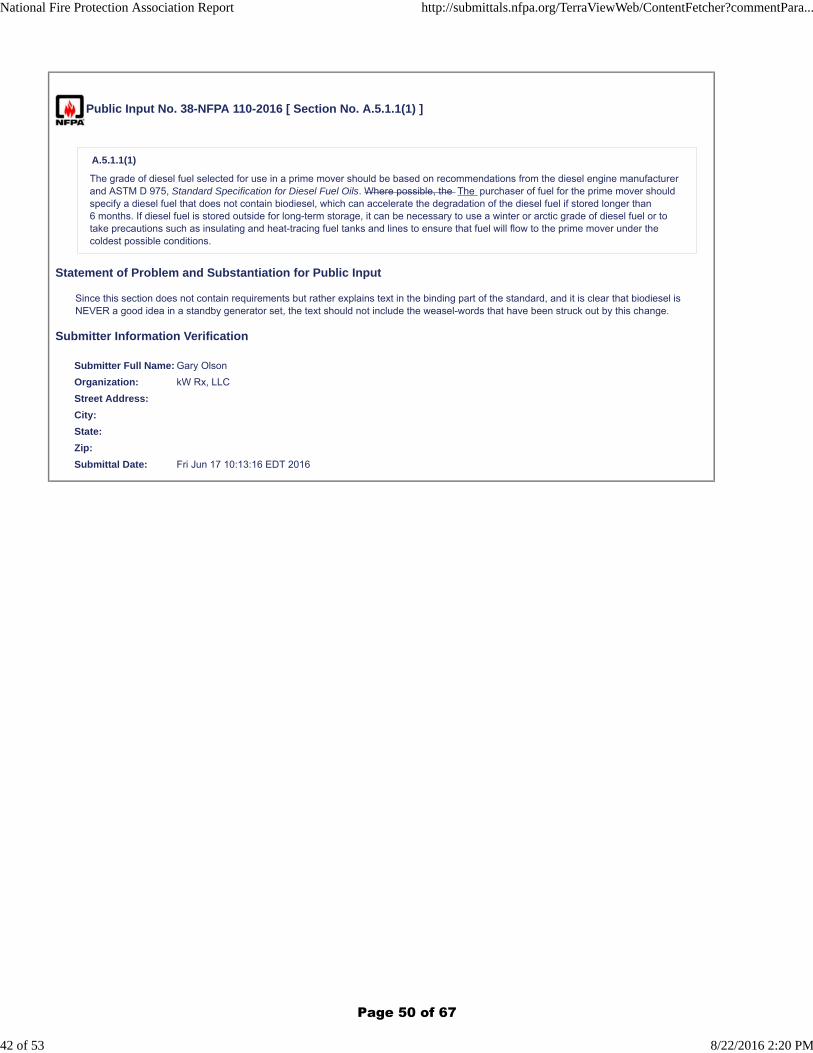
Public Input No. 38-NFPA 110-2016 [ Section No. A.5.1.1(1) ]
A.5.1.1(1)
The grade of diesel fuel selected for use in a prime mover should be based on recommendations from the diesel engine manufacturerand ASTM D 975, Standard Specification for Diesel Fuel Oils. Where possible, the The purchaser of fuel for the prime mover shouldspecify a diesel fuel that does not contain biodiesel, which can accelerate the degradation of the diesel fuel if stored longer than6 months. If diesel fuel is stored outside for long-term storage, it can be necessary to use a winter or arctic grade of diesel fuel or totake precautions such as insulating and heat-tracing fuel tanks and lines to ensure that fuel will flow to the prime mover under thecoldest possible conditions.
Statement of Problem and Substantiation for Public Input
Since this section does not contain requirements but rather explains text in the binding part of the standard, and it is clear that biodiesel is NEVER a good idea in a standby generator set, the text should not include the weasel-words that have been struck out by this change.
Submitter Information Verification
Submitter Full Name: Gary Olson
Organization: kW Rx, LLC
Street Address:
City:
State:
Zip:
Submittal Date: Fri Jun 17 10:13:16 EDT 2016
National Fire Protection Association Report http://submittals.nfpa.org/TerraViewWeb/ContentFetcher?commentPara...
42 of 53 8/22/2016 2:20 PM
Page 50 of 67
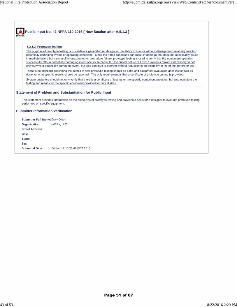
Public Input No. 42-NFPA 110-2016 [ New Section after A.5.1.3 ]
5.2.1.2 Prototype Testing
The purpose of prototype testing is to validate a generator set design for the ability to survive without damage from relatively rare butpotentially damaging events or operating conditions. Since the noted conditions can result in damage that does not necessarily causeimmediate failure but can result in unexpected or premature failure, prototype testing is used to verify that the equipment operatessuccessfully after a potentially damaging event occurs. In particular, the critical nature of Level 1 systems makes it necessary to notonly survive a potentially damaging event, but also continue to operate without reduction in the reliability or life of the generator set.
There is no standard describing the details of how prototype testing should be done and equipment evaluation after test should bedone, or what specific results should be reported. The only requirement is that a certificate of prototype testing is provided.
System designers should not only verify that there is a certificate of testing for the specific equipment provided, but also evalutate thetesting and results for the specific equipment provided for critical sites.
Statement of Problem and Substantiation for Public Input
This statement provides information on the objectives of prototype testing and provides a basis for a designer to evaluate prototype testing performed on specific equipment.
Submitter Information Verification
Submitter Full Name: Gary Olson
Organization: kW Rx, LLC
Street Address:
City:
State:
Zip:
Submittal Date: Fri Jun 17 10:28:48 EDT 2016
National Fire Protection Association Report http://submittals.nfpa.org/TerraViewWeb/ContentFetcher?commentPara...
43 of 53 8/22/2016 2:20 PM
Page 51 of 67
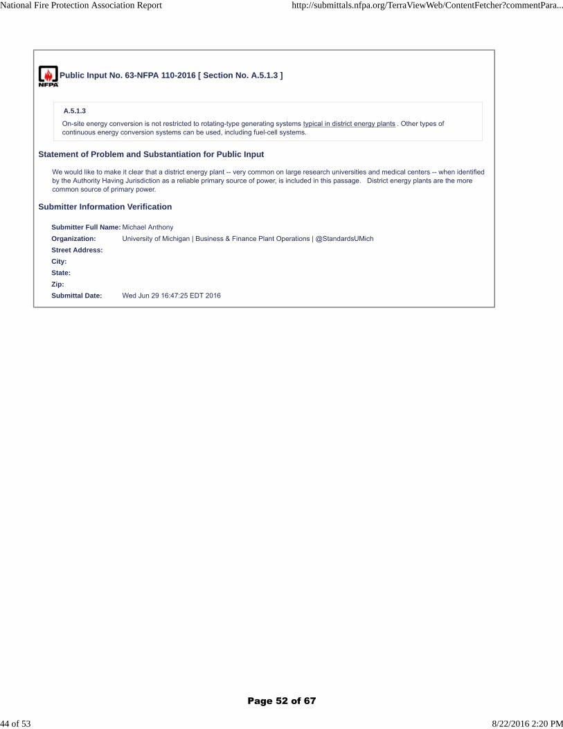
Public Input No. 63-NFPA 110-2016 [ Section No. A.5.1.3 ]
A.5.1.3
On-site energy conversion is not restricted to rotating-type generating systems typical in district energy plants . Other types ofcontinuous energy conversion systems can be used, including fuel-cell systems.
Statement of Problem and Substantiation for Public Input
We would like to make it clear that a district energy plant -- very common on large research universities and medical centers -- when identified by the Authority Having Jurisdiction as a reliable primary source of power, is included in this passage. District energy plants are the more common source of primary power.
Submitter Information Verification
Submitter Full Name: Michael Anthony
Organization: University of Michigan | Business & Finance Plant Operations | @StandardsUMich
Street Address:
City:
State:
Zip:
Submittal Date: Wed Jun 29 16:47:25 EDT 2016
National Fire Protection Association Report http://submittals.nfpa.org/TerraViewWeb/ContentFetcher?commentPara...
44 of 53 8/22/2016 2:20 PM
Page 52 of 67
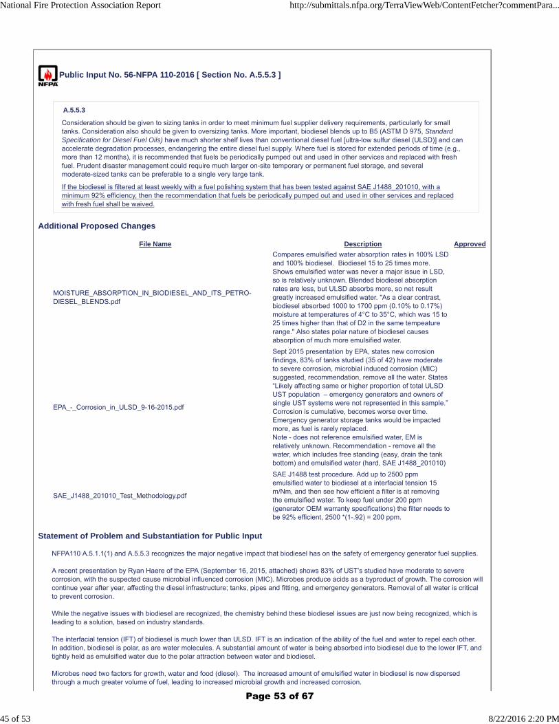
Public Input No. 56-NFPA 110-2016 [ Section No. A.5.5.3 ]
A.5.5.3
Consideration should be given to sizing tanks in order to meet minimum fuel supplier delivery requirements, particularly for smalltanks. Consideration also should be given to oversizing tanks. More important, biodiesel blends up to B5 (ASTM D 975, StandardSpecification for Diesel Fuel Oils) have much shorter shelf lives than conventional diesel fuel [ultra-low sulfur diesel (ULSD)] and canaccelerate degradation processes, endangering the entire diesel fuel supply. Where fuel is stored for extended periods of time (e.g.,more than 12 months), it is recommended that fuels be periodically pumped out and used in other services and replaced with freshfuel. Prudent disaster management could require much larger on-site temporary or permanent fuel storage, and severalmoderate-sized tanks can be preferable to a single very large tank.
If the biodiesel is filtered at least weekly with a fuel polishing system that has been tested against SAE J1488_201010, with aminimum 92% efficiency, then the recommendation that fuels be periodically pumped out and used in other services and replacedwith fresh fuel shall be waived.
Additional Proposed Changes
File Name Description Approved
MOISTURE_ABSORPTION_IN_BIODIESEL_AND_ITS_PETRO-DIESEL_BLENDS.pdf
Compares emulsified water absorption rates in 100% LSD and 100% biodiesel. Biodiesel 15 to 25 times more. Shows emulsified water was never a major issue in LSD, so is relatively unknown. Blended biodiesel absorption rates are less, but ULSD absorbs more, so net result greatly increased emulsified water. "As a clear contrast, biodiesel absorbed 1000 to 1700 ppm (0.10% to 0.17%) moisture at temperatures of 4°C to 35°C, which was 15 to 25 times higher than that of D2 in the same tempeature range." Also states polar nature of biodiesel causes absorption of much more emulsified water.
EPA_-_Corrosion_in_ULSD_9-16-2015.pdf
Sept 2015 presentation by EPA, states new corrosion findings, 83% of tanks studied (35 of 42) have moderate to severe corrosion, microbial induced corrosion (MIC) suggested, recommendation, remove all the water. States “Likely affecting same or higher proportion of total ULSD UST population – emergency generators and owners of single UST systems were not represented in this sample.” Corrosion is cumulative, becomes worse over time. Emergency generator storage tanks would be impacted more, as fuel is rarely replaced. Note - does not reference emulsified water, EM is relatively unknown. Recommendation - remove all the water, which includes free standing (easy, drain the tank bottom) and emulsified water (hard, SAE J1488_201010)
SAE_J1488_201010_Test_Methodology.pdf
SAE J1488 test procedure. Add up to 2500 ppm emulsified water to biodiesel at a interfacial tension 15 m/Nm, and then see how efficient a filter is at removing the emulsified water. To keep fuel under 200 ppm (generator OEM warranty specifications) the filter needs to be 92% efficient, 2500 *(1-.92) = 200 ppm.
Statement of Problem and Substantiation for Public Input
NFPA110 A.5.1.1(1) and A.5.5.3 recognizes the major negative impact that biodiesel has on the safety of emergency generator fuel supplies.
A recent presentation by Ryan Haere of the EPA (September 16, 2015, attached) shows 83% of UST’s studied have moderate to severe corrosion, with the suspected cause microbial influenced corrosion (MIC). Microbes produce acids as a byproduct of growth. The corrosion will continue year after year, affecting the diesel infrastructure; tanks, pipes and fitting, and emergency generators. Removal of all water is critical to prevent corrosion.
While the negative issues with biodiesel are recognized, the chemistry behind these biodiesel issues are just now being recognized, which is leading to a solution, based on industry standards.
The interfacial tension (IFT) of biodiesel is much lower than ULSD. IFT is an indication of the ability of the fuel and water to repel each other. In addition, biodiesel is polar, as are water molecules. A substantial amount of water is being absorbed into biodiesel due to the lower IFT, and tightly held as emulsified water due to the polar attraction between water and biodiesel.
Microbes need two factors for growth, water and food (diesel). The increased amount of emulsified water in biodiesel is now dispersed through a much greater volume of fuel, leading to increased microbial growth and increased corrosion.
National Fire Protection Association Report http://submittals.nfpa.org/TerraViewWeb/ContentFetcher?commentPara...
45 of 53 8/22/2016 2:20 PM
Page 53 of 67
In pre ULSD fuel, the microbial growth was limited to the fuel/water interface, a very narrow band. In biodiesel, the larger amount of emulsified water in the fuel provides a substantially greater growth volume, leading to increased corrosion.
SAE J1488 is the fuel industry recognized test “To determine the ability of a fuel/water separator to separate emulsified or finely dispersed water from fuels.“ This standard was updated in October 2010 (SAE J1488_201010) to reflect the lower IFT in biodiesel and ULSD. Filters designed to meet this standard can remove most, if not all, the emulsified water in biodiesel, preventing microbial growth, MIC., and degradation of the fuel. A filter with a minimum 92% efficiency rating can keep water below 200 ppm: 2500 * (1-.92) = 200.
Removal of all the water (free standing and emulsified) can prevent corrosion and the degradation of the fuel.
In June 2016, the British BS5410-3 standard for critical emergency backup generators was updated to include the requirement for SAE J1488_201010 capable filters to be used if any filters are used.
Submitter Information Verification
Submitter Full Name: Pat Smyth
Organization: DieselPure
Street Address:
City:
State:
Zip:
Submittal Date: Tue Jun 28 18:25:16 EDT 2016
National Fire Protection Association Report http://submittals.nfpa.org/TerraViewWeb/ContentFetcher?commentPara...
46 of 53 8/22/2016 2:20 PM
Page 54 of 67
Public Input No. 39-NFPA 110-2016 [ Section No. A.5.6.4.6 ]
A.5.6.4.6
It is intended that the battery charger be factory-built, adjusted, and approved for the specific type, construction, and capacity of thebattery. For lead-acid batteries, the battery charger should be tested for the specific gravity, type, and concentration of grid alloys,such as high or low gravity, high or low antimony, calcium, or none.
Statement of Problem and Substantiation for Public Input
The word "charger" appears to be a typo--as the text clearing is relating to batteries not chargers.
Submitter Information Verification
Submitter Full Name: Gary Olson
Organization: kW Rx, LLC
Street Address:
City:
State:
Zip:
Submittal Date: Fri Jun 17 10:17:24 EDT 2016
National Fire Protection Association Report http://submittals.nfpa.org/TerraViewWeb/ContentFetcher?commentPara...
47 of 53 8/22/2016 2:20 PM
Page 55 of 67
Public Input No. 40-NFPA 110-2016 [ Section No. A.5.6.5.6 ]
A.5.6.5.6
For systems located outdoors, the manual shutdown should be located external to the weatherproof enclosure and should beappropriately identified. Note that the manual shutdown is not required to be physically on the generator set, but may be in a locationwhich is protected from malicious operation.
Statement of Problem and Substantiation for Public Input
Provides additional clarity on the purpose and required location of an emergency stop switch for an outdoor generator.
Submitter Information Verification
Submitter Full Name: Gary Olson
Organization: kW Rx, LLC
Street Address:
City:
State:
Zip:
Submittal Date: Fri Jun 17 10:18:58 EDT 2016
National Fire Protection Association Report http://submittals.nfpa.org/TerraViewWeb/ContentFetcher?commentPara...
48 of 53 8/22/2016 2:20 PM
Page 56 of 67
Public Input No. 41-NFPA 110-2016 [ Section No. A.6.2.15 ]
A.6.2.15
ATSs can be provided with accessory controls that provide a signal to operate remote motor controls that disconnect motors prior totransfer and to reconnect them after transfer when the residual voltage has been substantially reduced. Another method is to providein-phase monitors within the ATS in order to prevent retransfer to the primary source until both sources are nearly synchronized. Athird method is to use a programmed neutral position transfer switch. See Section 230.95 of NFPA 70 , National Electrical Code .
Statement of Problem and Substantiation for Public Input
230.95 describes ground fault protection which has nothing to do with transfer switch operation when switching inductive loads.
Submitter Information Verification
Submitter Full Name: Gary Olson
Organization: kW Rx, LLC
Street Address:
City:
State:
Zip:
Submittal Date: Fri Jun 17 10:23:11 EDT 2016
National Fire Protection Association Report http://submittals.nfpa.org/TerraViewWeb/ContentFetcher?commentPara...
49 of 53 8/22/2016 2:20 PM
Page 57 of 67
Public Input No. 59-NFPA 110-2016 [ Section No. A.7.9.1.2 ]
A.7.9.1.2
To optimize the long-term storage of fuels for prime movers, the fuel tanks should be kept cool and dry, and the tank as full aspossible. Tanks that are subject to temperature variations can experience accelerated fuel degradation, especially if the tanks areoutside and above ground or close to an extreme heat source if stored inside a structure. The more constant and cooler the tanktemperatures, the less likely temperature-related fuel degradation will occur. Tank ullage (air space) should be kept to a minimum.Excess air space allows for warm, humid air to enter the tank and condense moisture during the cool evening. Also, prolongedexposure to ambient air, which is 20 percent oxygen, can facilitate oxidative degradation of the fuel. Fuel storage tanks should be keptas dry as possible and have provisions for water drainage on a regular basis. The presence of water can lead to microbiologicalcontamination and growth, which in turn can lead to general or pitting corrosion of steel tanks and components, possibly resulting infilter plugging, operational issues, or a hydrocarbon release to the environment. Regularly scheduled surveillance of the fuel allowsthe operator(s) to evaluate the condition of the fuel and make important decisions regarding the quality of the fuel dedicated to reliableoperation of the prime mover. Fuel maintenance and testing should begin the day of installation and first fill in order to establish abenchmark guideline for future comparison. Laboratory testing services should always be sought from a qualified or certifiedpetroleum laboratory.
Biodiesel blends cause free standing water to become emulsified and held in the fuel column. To remove the eulsified water, filters areto be used that have been tested against SAE J1488_201010, with a minimum efficiency of 92%
Additional Proposed Changes
File Name Description Approved
MOISTURE_ABSORPTION_IN_BIODIESEL_AND_ITS_PETRO-DIESEL_BLENDS.pdf
Compares emulsified water absorption rates between 100% LSD and 100% biodiesel, biodiesel absorbs 15 to 25 times more emulsified water than LSD. Biodiesel and water are both polar, so the emulsified water is tightly held
SAE_J1488_201010_Test_Methodology.pdf
SAE J1488_201010 is the industry recognized test that assign an efficiency rating to a filter at removing emulsified water.“To determine the ability of a fuel/water separator to separate emulsified or finely dispersed water from fuels. “Tests ULSD, biodiesel blends, and Jet A fuel.Standard updated October 2010 to reflect lower IFT in ULSD and Biodiesel, LSD filters do not pass
Statement of Problem and Substantiation for Public Input
Emulsified water is a new problem with the adoption of biodiesel blends. The additional emulsified water in the fuel column is providing an increased growth volume for microbes, some of which produce acids. The emulsified water is tightly held in the fuel because both biodiesel and water are polar molecules and attracted to each other. In addition, the Interfacial Tension (IFT) of biodiesel is much lower than ULSD. SAE J1488 is “To determine the ability of a fuel/water separator to separate emulsified or finely dispersed water from fuels. “ J1488 was updated in 2010 to J1488_201010, to take into account the lower IFT of biodiesel. The test procedure injects 2500 ppm emulsified water into the fuel, then gives an efficiency at removing emulsified water. A 92% efficiency in needed to keep fuels below 200 ppm, OEM warranty levels. 2500 * (1-.92) = 200 ppm
Submitter Information Verification
Submitter Full Name: Pat Smyth
Organization: DieselPure
Street Address:
City:
State:
Zip:
Submittal Date: Wed Jun 29 12:42:13 EDT 2016
National Fire Protection Association Report http://submittals.nfpa.org/TerraViewWeb/ContentFetcher?commentPara...
50 of 53 8/22/2016 2:20 PM
Page 58 of 67
Public Input No. 58-NFPA 110-2016 [ Section No. A.8.3.7 ]
A.8.3.7
Limited fuel quality testing performed annually using appropriate ASTM standard test methods is recommended as a means todetermine that existing fuel inventories are suitable for continued long-term storage. Special attention should be paid to sampling thebottom of the storage tank to verify that the stored fuel is as clean and dry as practicable and that water, sediment, or microbial growthon the tank bottom is minimized. ASTM D 975, Standard Specification for Diesel Fuel Oils, contains test methods for existing dieselfuel.
Special attention should be paid to sampling the storage tank to verify that the stored fuel is as clean and dry as practicable and thatwater (both free standing water on the bottom, and emulsified water held in the fuel column), sediment, or microbial growth on the tankbottom is minimized.
Statement of Problem and Substantiation for Public Input
Biodiesel absorbs large amounts of emulsified water, due to a low interfacial tension, and because both biodiesel and water are polar molecules which tightly attach to each other. Emulsified water is not visible to the naked eye, and is held in suspension indefinitely, i.e. it does nor precipitate out of the fuel onto the bottom. The additional emulsified water in the fuel column provides a greater growth volume for microbes, some of which produce acids as a byproduct of growth. The amount of microbes is increasing, and the fuel is acidifying, corroding the diesel infrastructure.
Submitter Information Verification
Submitter Full Name: Pat Smyth
Organization: DieselPure
Street Address:
City:
State:
Zip:
Submittal Date: Wed Jun 29 10:47:56 EDT 2016
National Fire Protection Association Report http://submittals.nfpa.org/TerraViewWeb/ContentFetcher?commentPara...
51 of 53 8/22/2016 2:20 PM
Page 59 of 67
Public Input No. 2-NFPA 110-2015 [ Chapter C ]
Annex C Informational References
C.1 Referenced Publications.
The documents or portions thereof listed in this annex are referenced within the informational sections of this standard and are notpart of the requirements of this document unless also listed in Chapter 2 for other reasons.
C.1.1 NFPA Publications.
National Fire Protection Association, 1 Batterymarch Park, Quincy, MA 02169-7471.
NFPA 20, Standard for the Installation of Stationary Pumps for Fire Protection, 2013 edition.
NFPA 37, Standard for the Installation and Use of Stationary Combustion Engines and Gas Turbines, 2014 edition.
NFPA 54, National Fuel Gas Code, 2015 edition.
NFPA 56, Standard for Fire and Explosion Prevention During Cleaning and Purging of Flammable Gas Piping Systems, 2014 edition.
NFPA 58, Liquefied Petroleum Gas Code, 2014 edition.
NFPA 70 ®, National Electrical Code ®, 2014 edition.
NFPA 70B, Recommended Practice for Electrical Equipment Maintenance, 2013 edition.
NFPA 99, Health Care Facilities Code, 2015 edition.
NFPA 101 ®, Life Safety Code ®, 2015 edition.
NFPA 111, Standard on Stored Electrical Energy Emergency and Standby Power Systems, 2016 edition.
C.1.2 Other Publications.
C.1.2.1 ANSI Publications.
American National Standards Institute, Inc., 25 West 43rd Street, 4th Floor, New York, NY 10036.
ANSI/NEMA C 84.1, Standard for Electric Power Systems and Equipment — Voltage Ratings (60 hertz), 2006 2011 .
C.1.2.2 ASCE Publications.
American Society of Civil Engineers, 1801 Alexander Bell Drive, Reston, VA 20191.
ASCE/SEI 7, Minimum Design Loads for Buildings and Other Structures, 2010.
C.1.2.3 ASTM Publications.
ASTM International, 100 Barr Harbor Drive, P.O. Box C700, West Conshocken, PA 19428-2959.
ASTM D 975 D975 , Standard Specification for Diesel Fuel Oils,2011b 2015c .
ASTM D 1835 D1835 , Standard Specification for Liquefied Petroleum (LP) Gases, 2011 2013 .
C.1.2.4 IEEE Publications.
IEEE, Three Park Avenue, 17th Floor, New York, NY 10016-5997.
ANSI/IEEE 493, Recommended Practice for the Design of Reliable Industrial and Commercial Power Systems, 2007.
C.1.2.5 NEMA Publications.
National Electrical Manufacturers Association, 1300 North 17th Street, Suite, 1847 900 , Rosslyn Arlington , VA 22209.
ANSI/ NEMA MG 1, Standard for Motors and Generators, 2009 2016 .
ANSI/ NEMA MG 2, Safety Standard and Guide for Selection, Installation and Use of Electric Motors and Generators, 2001, Revision1, 2007 2014 .
C.1.2.6 NHC Publications.
National Hurricane Center, 11691 SW 17th Street, Miami, FL 33165-2149.
SLOSH (Sea, Lake and Overland Surges from Hurricanes) Model.
C.1.2.7 U.S. Government Publications.
FEMA 543, Design Guide for Improving Critical Facility Safety from Flooding and High Winds, 2007.
FEMA 577, Design Guide for Improving Hospital Safety in Earthquakes, Floods, and High Winds, 2007.
C.2 Informational References.
The following documents or portions thereof are listed here as informational resources only. They are not a part of the requirementsof this document.
National Fire Protection Association Report http://submittals.nfpa.org/TerraViewWeb/ContentFetcher?commentPara...
52 of 53 8/22/2016 2:20 PM
Page 60 of 67
C.2.1 NFPA Publications.
National Fire Protection Association, 1 Batterymarch Park, Quincy, MA 02169-7471.
NFPA 72 ®, National Fire Alarm and Signaling Code, 2013 edition.
C.3 References for Extracts in Informational Sections. (Reserved)
Statement of Problem and Substantiation for Public Input
Referenced current SDO names, addresses, standard names, numbers, and editions.
Submitter Information Verification
Submitter Full Name: Aaron Adamczyk
Organization: [ Not Specified ]
Street Address:
City:
State:
Zip:
Submittal Date: Thu Dec 24 22:55:40 EST 2015
National Fire Protection Association Report http://submittals.nfpa.org/TerraViewWeb/ContentFetcher?commentPara...
53 of 53 8/22/2016 2:20 PM
Page 61 of 67
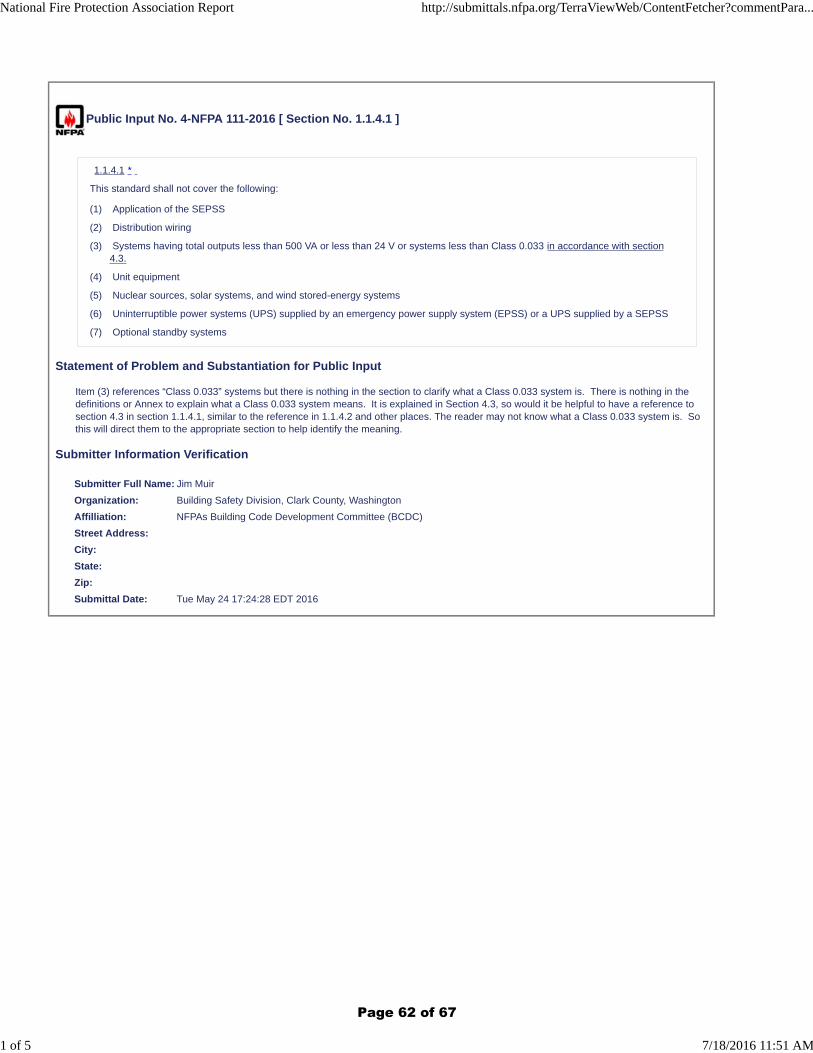
Public Input No. 4-NFPA 111-2016 [ Section No. 1.1.4.1 ]
1.1.4.1 *
This standard shall not cover the following:
(1) Application of the SEPSS
(2) Distribution wiring
(3) Systems having total outputs less than 500 VA or less than 24 V or systems less than Class 0.033 in accordance with section4.3.
(4) Unit equipment
(5) Nuclear sources, solar systems, and wind stored-energy systems
(6) Uninterruptible power systems (UPS) supplied by an emergency power supply system (EPSS) or a UPS supplied by a SEPSS
(7) Optional standby systems
Statement of Problem and Substantiation for Public Input
Item (3) references “Class 0.033” systems but there is nothing in the section to clarify what a Class 0.033 system is. There is nothing in the definitions or Annex to explain what a Class 0.033 system means. It is explained in Section 4.3, so would it be helpful to have a reference to section 4.3 in section 1.1.4.1, similar to the reference in 1.1.4.2 and other places. The reader may not know what a Class 0.033 system is. So this will direct them to the appropriate section to help identify the meaning.
Submitter Information Verification
Submitter Full Name: Jim Muir
Organization: Building Safety Division, Clark County, Washington
Affilliation: NFPAs Building Code Development Committee (BCDC)
Street Address:
City:
State:
Zip:
Submittal Date: Tue May 24 17:24:28 EDT 2016
National Fire Protection Association Report http://submittals.nfpa.org/TerraViewWeb/ContentFetcher?commentPara...
1 of 5 7/18/2016 11:51 AM
Page 62 of 67
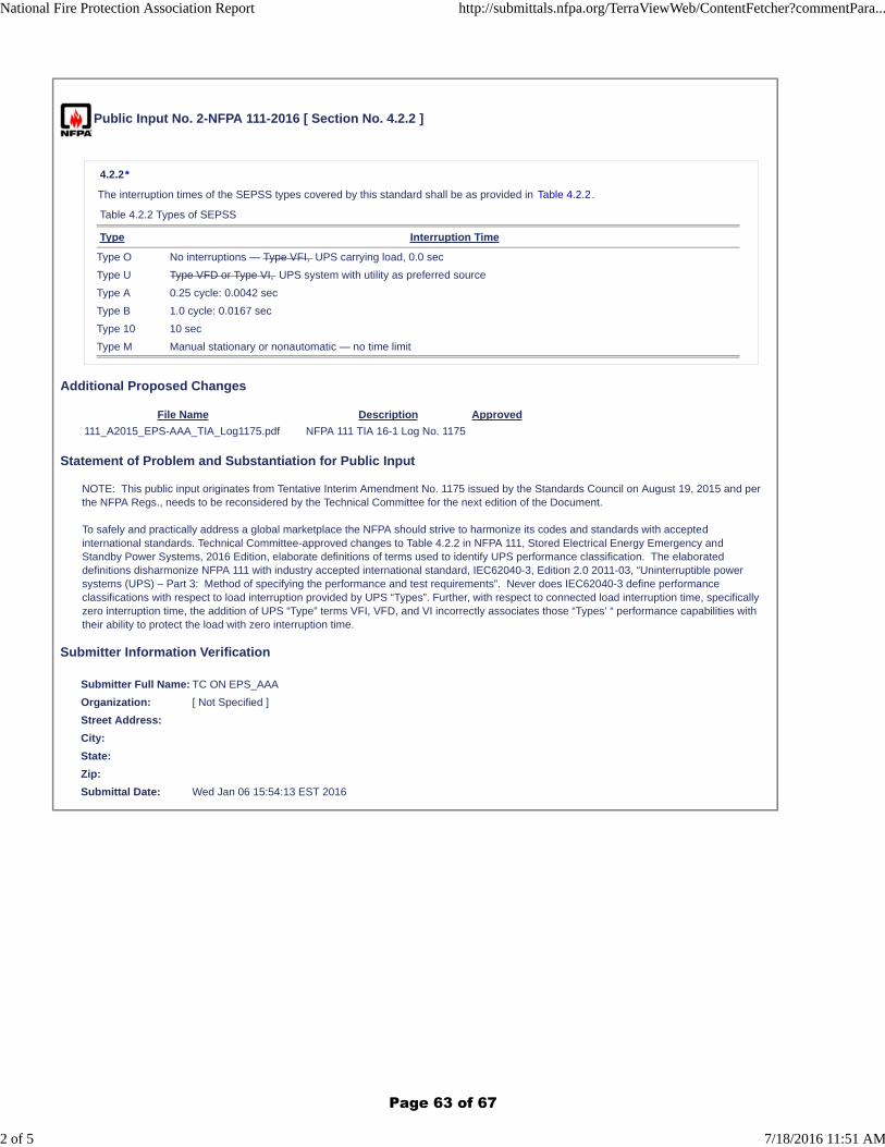
Public Input No. 2-NFPA 111-2016 [ Section No. 4.2.2 ]
4.2.2*
The interruption times of the SEPSS types covered by this standard shall be as provided in Table 4.2.2.
Table 4.2.2 Types of SEPSS
Type Interruption Time
Type O No interruptions — Type VFI, UPS carrying load, 0.0 sec
Type U Type VFD or Type VI, UPS system with utility as preferred source
Type A 0.25 cycle: 0.0042 sec
Type B 1.0 cycle: 0.0167 sec
Type 10 10 sec
Type M Manual stationary or nonautomatic — no time limit
Additional Proposed Changes
File Name Description Approved
111_A2015_EPS-AAA_TIA_Log1175.pdf NFPA 111 TIA 16-1 Log No. 1175
Statement of Problem and Substantiation for Public Input
NOTE: This public input originates from Tentative Interim Amendment No. 1175 issued by the Standards Council on August 19, 2015 and per the NFPA Regs., needs to be reconsidered by the Technical Committee for the next edition of the Document.
To safely and practically address a global marketplace the NFPA should strive to harmonize its codes and standards with accepted international standards. Technical Committee-approved changes to Table 4.2.2 in NFPA 111, Stored Electrical Energy Emergency and Standby Power Systems, 2016 Edition, elaborate definitions of terms used to identify UPS performance classification. The elaborated definitions disharmonize NFPA 111 with industry accepted international standard, IEC62040-3, Edition 2.0 2011-03, “Uninterruptible power systems (UPS) – Part 3: Method of specifying the performance and test requirements”. Never does IEC62040-3 define performance classifications with respect to load interruption provided by UPS “Types”. Further, with respect to connected load interruption time, specifically zero interruption time, the addition of UPS “Type” terms VFI, VFD, and VI incorrectly associates those “Types’ “ performance capabilities with their ability to protect the load with zero interruption time.
Submitter Information Verification
Submitter Full Name: TC ON EPS_AAA
Organization: [ Not Specified ]
Street Address:
City:
State:
Zip:
Submittal Date: Wed Jan 06 15:54:13 EST 2016
National Fire Protection Association Report http://submittals.nfpa.org/TerraViewWeb/ContentFetcher?commentPara...
2 of 5 7/18/2016 11:51 AM
Page 63 of 67
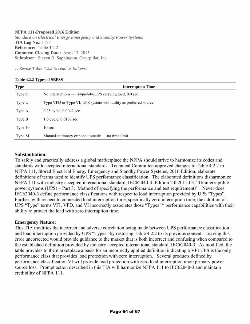
NFPA 111-Proposed 2016 Edition Standard on Electrical Energy Emergency and Standby Power Systems TIA Log No.: 1175 Reference: Table 4.2.2 Comment Closing Date: April 17, 2015 Submitter: Steven R. Sappington, Caterpillar, Inc. 1. Revise Table 4.2.2 to read as follows: Table 4.2.2 Types of SEPSS
Type Interruption Time
Type O No interruptions — Type VFI,UPS carrying load, 0.0 sec
Type U Type VFD or Type VI, UPS system with utility as preferred source
Type A 0.25 cycle: 0.0042 sec
Type B 1.0 cycle: 0.0167 sec
Type 10 10 sec
Type M Manual stationary or nonautomatic — no time limit
Substantiation: To safely and practically address a global marketplace the NFPA should strive to harmonize its codes and standards with accepted international standards. Technical Committee-approved changes to Table 4.2.2 in NFPA 111, Stored Electrical Energy Emergency and Standby Power Systems, 2016 Edition, elaborate definitions of terms used to identify UPS performance classification. The elaborated definitions disharmonize NFPA 111 with industry accepted international standard, IEC62040-3, Edition 2.0 2011-03, “Uninterruptible power systems (UPS) – Part 3: Method of specifying the performance and test requirements”. Never does IEC62040-3 define performance classifications with respect to load interruption provided by UPS “Types”. Further, with respect to connected load interruption time, specifically zero interruption time, the addition of UPS “Type” terms VFI, VFD, and VI incorrectly associates those “Types’ “ performance capabilities with their ability to protect the load with zero interruption time. Emergency Nature: This TIA modifies the incorrect and adverse correlation being made between UPS performance classification and load interruption provided by UPS “Types” by restoring Table 4.2.2 to its previous content. Leaving this error uncorrected would provide guidance to the market that is both incorrect and confusing when compared to the established definition provided by industry accepted international standard, IEC62040-3. As modified, the table provides to the marketplace a basis for an incorrectly applied definition indicating a VFI UPS is the only performance class that provides load protection with zero interruption. Several products defined by performance classification VI will provide load protection with zero load interruption upon primary power source loss. Prompt action described in this TIA will harmonize NFPA 111 to IEC62040-3 and maintain credibility of NFPA 111.
Page 64 of 67

Public Input No. 1-NFPA 111-2015 [ Chapter C ]
Annex C Informational References
C.1 Referenced Publications.
The documents or portions thereof listed in this annex are referenced within the informational sections of this standard and are notpart of the requirements of this document unless also listed in Chapter 2 for other reasons.
C.1.1 NFPA Publications.
National Fire Protection Association, 1 Batterymarch Park, Quincy, MA 02169-7471.
NFPA 70 ®, National Electrical Code ®, 2014 edition.
NFPA 99, Health Care Facilities Code, 2015 edition.
NFPA 101 ®, Life Safety Code ®, 2015 edition.
NFPA 110, Standard for Emergency and Standby Power Systems, 2016 edition.
C.1.2 Other Publications.
C.1.2.1 ANSI Publications.
American National Standards Institute, Inc., 25 West 43rd Street, 4th floor, New York, NY 10036.
NEMA/ ANSI C84.1, American National Standard for Electric Power Systems and Equipment — Voltage Ratings (60 Hertz), 2011.
C.1.2.2 IEC Publications.
International Electrotechnical Commission, 3, rue de Varembé, P.O. Box 131, CH-1211 Geneva 20, Switzerland.
IEC 62040-3, Uninterruptible Power Systems (UPS)-Part 3: Method of Specifying the Performance and Test Requirements, 2011.
C.1.2.3 IEEE Publications.
IEEE, Three Park Avenue, 17th Floor, New York, NY 10016-5997.
IEEE 450, Recommended Practice for Maintenance, Testing, and Replacement of Vented Lead-Acid Batteries for StationaryApplications, 2010.
IEEE 1106, Recommended Practice for Maintenance, Testing, and Replacement of Vented Nickel-Cadmium Batteries for StationaryApplications, 2005 2015 .
IEEE 1188, Recommended Practice for Maintenance, Testing and Replacement of Valve-Regulated Lead-Acid Batteries for StationaryApplications, 2005, Amendment 1, 2014 .
C.1.2.4 UL Publications.
Underwriters Laboratories Inc., 333 Pfingsten Road, Northbrook, IL 60062-2096.
ANSI/UL 1008, Standard for Safety Transfer Switch Equipment, 2012.
C.2 Informational References.
The following documents or portions thereof are listed here as informational resources only. They are not a part of the requirementsof this document.
C.2.1 NFPA Publications.
National Fire Protection Association, 1 Batterymarch Park, Quincy, MA 02169-7471.
NFPA 70B, Recommended Practice for Electrical Equipment Maintenance, 2013 edition.
C.2.2 IEEE Publications.
IEEE, Three Park Avenue, 17th Floor, New York, NY 10016-5997.
ANSI/ IEEE 446, Recommended Practice for Emergency and Standby Power Systems for Industrial and Commercial Applications,2002 1995, reaffirmed 2000 .
ANSI/ IEEE 484, Recommended Practice for Installation Design and Installation of Vented Lead-Acid Batteries for StationaryApplications, 2002, reaffirmed 2008.
IEEE 485, Recommended Practice for Sizing Lead-Acid Batteries for Stationary Applications, 2010.
ANSI/ IEEE 944, Recommended Practice for the Application and Testing of Uninterruptible Power Supplies for Power GeneratingSystems, 1996. (Only Avialable in electronic format)
C.3 References for Extracts in Informational Sections.
NFPA 1, Fire Code, 2015 edition.
Statement of Problem and Substantiation for Public Input
Referenced current editions.
National Fire Protection Association Report http://submittals.nfpa.org/TerraViewWeb/ContentFetcher?commentPara...
3 of 5 7/18/2016 11:51 AM
Page 65 of 67

Submitter Information Verification
Submitter Full Name: Aaron Adamczyk
Organization: [ Not Specified ]
Street Address:
City:
State:
Zip:
Submittal Date: Thu Dec 24 23:07:22 EST 2015
National Fire Protection Association Report http://submittals.nfpa.org/TerraViewWeb/ContentFetcher?commentPara...
4 of 5 7/18/2016 11:51 AM
Page 66 of 67
Public Input No. 5-NFPA 111-2016 [ Section No. C.1.2.4 ]
C.1.2.4 UL Publications.
Underwriters Laboratories Inc., 333 Pfingsten Road, Northbrook, IL 60062-2096.
ANSI/UL 1008, Standard for Safety Transfer Switch Equipment, 2012 2014 .
Statement of Problem and Substantiation for Public Input
This proposal updates the referenced UL Standards to the current edition.
Submitter Information Verification
Submitter Full Name: Ronald Farr
Organization: UL LLC
Street Address:
City:
State:
Zip:
Submittal Date: Mon Jun 27 17:05:11 EDT 2016
National Fire Protection Association Report http://submittals.nfpa.org/TerraViewWeb/ContentFetcher?commentPara...
5 of 5 7/18/2016 11:51 AM
Page 67 of 67


![Washington - Reprint 1. Ringold Formation of Pleistocene age in … · 2020-05-28 · [AMERICAN JouRNAL or SCIENCE, VoL. 256, MAY 1958, P. 328-34-0] RINGOLD FORMATION OF PLEISTOCENE](https://img.pdfslide.us/doc/110x75/5f44d57d0018d723571bdc1c/washington-reprint-1-ringold-formation-of-pleistocene-age-in-2020-05-28-american.jpg)