Embed Size (px)
Citation preview
1
FIRE TESTS CARRIED OUT IN FCH JU FIRECOMP PROJECT,
RECOMMENDATIONS AND APPLICATION TO SAFETY OF GAS
STORAGE SYSTEMS
P. Blanc-Vannet
1*, S.Jallais
1, B.Fuster
1, F.Fouillen
2, D.Halm
3, T.van Eekelen
4, S.Welch
5,
P.Breuer6, S.Hawksworth
7
1 Air Liquide Research and Development, 1 Chemin de la porte des loges, BP 126 - 78354 Jouy
en Josas, France, [email protected] 2 INERIS, Rue Jacques Taffanel, 60550 Verneuil-en-Halatte
3 Institut Pprime, CNRS – ENSMA – Université de Poitiers, Chasseneuil, France
4 Samtech SA – a Siemens company, Liège, Belgium
5 School of Engineering, The University of Edinburgh, Edinburgh, EH9 3JL, UK
6 Hexagon Composites, Raufoss, Norway
7 Health and Safety Laboratory, Buxton, Derbyshire, UK
ABSTRACT
In the event of a fire, composite pressure vessels behave very differently from metallic ones: the
material is degraded, potentially leading to a burst without significant pressure increase. Hence, such
objects are, when necessary, protected from fire by using thermally-activated devices (TPRD), and
standards require testing cylinder and TPRD together. The pre-normative research project FireComp
aimed at understanding better the conditions which may lead to burst, through testing and simulation,
and proposed an alternative way of assessing the fire performance of composite cylinders. This
approach is currently used by Air Liquide for the safety of composite bundles carrying large amounts
of hydrogen gas.
NOMENCLATURE
TPRD Thermally activated Pressure Relief Device
Thermal energy stored by the gas
Temperature of the gas
Mass of gas
Mass of the cylinder
Specific heat capacity
Specific heat capacity of the steel
/ Internal / External wall surface
Heat flux transmitted by the internal wall surface
Net heat flux absorbed by the vessel
Average temperature of the internal wall of the cylinder
Areal transfer coefficient between gas and inner wall
Heat flux absorbed by the cylinder
Thermal conductivity
Thickness
1.0 INTRODUCTION
Type IV pressure vessels, typically made of a carbon fibre-epoxy composite shell wrapped around a
polymeric liner, are considered a mature way of storing hydrogen at high pressure. Their use is
increasing for applications requiring lightness and/or high pressure, such as on-board storage for cars
or large vessels mounted on trailers. Though they can already be operated safely, a number of material
issues and R&D challenges still limit their optimisation potential, including fire behaviour [1].
2
When exposed to fire, composite pressure vessels exhibit a completely different behaviour than
metallic ones. For the latter, the heat is rapidly transferred to the gas, leading to a pressure increase,
and ultimately cylinder burst when the pressure gets too high. On the other hand, the pressure in
composite vessels tends not increase much more than about 10%, whereas vessels are designed with
safety factors of 2.25 to 3. The degradation of the composite material can lead directly to a burst, or
the melting of the plastic liner can lead to a leakage through the vessel’s body. Whichever happens
first depends on fire conditions, materials properties and tank geometry [1, 2]. Due to the high energy
content, the burst must be avoided, and the cylinders are protected with thermally activated pressure
relief devices (TPRD), which must be placed in a way that ensures they detect the fire and vent the gas
as required [3].
In current standards addressing the qualification of composite cylinders, either for on-board storage [4]
or for transportable applications [5], it is required to test the vessel and its TPRD together in a bonfire
test. The test is deemed a success if the gas vents through the TPRD and no burst occurs. For
transportable applications in Europe, the use of TPRD is not mandatory: in that case, the cylinder must
not burst before 2 minutes. A disadvantage of this method is that it does not provide much information
on what the vessel alone can endure.
The European project FireComp [6, 7], a three-year FCH JU funded pre-normative research project
which ended in June 2016, aimed at providing a better understanding of the failure of unprotected
composite pressure vessels in fire. It brought together partners with different expertise: a hydrogen
supplier as coordinator (Air Liquide), a composite vessels manufacturer (Hexagon), experts of
industrial risks and safety (INERIS and HSL), experts in thermal radiation and mechanical behaviour
of composites (CNRS, Samtech), in thermal degradation and reaction-to-fire (University of
Edinburgh) and in collaborative research projects management (Ayming). Within the project an
extensive bonfire test campaign was performed on 19L and 36L cylinders. Models were developed for
heat transfer through the composite thickness [8] and loss of material strength with temperature [9,
10]. Used on real cylinder geometry, they proved able to accurately reproduce the experimental results
and capture the transition between leak and burst failure modes [11].
This paper presents the fire test setup that was used, how the thermal aggression was calibrated using a
metallic tube, the experimental results obtained, and how this knowledge is used for the fire protection
of composite trailers.
2.0 BONFIRE TESTS SETUP AND CALIBRATION
The risk analysis underlined three possible types of fire: “punctual” jet fire (e.g. from an ignited
hydrogen jet from piping), localised fire exposing a part of the cylinder (e.g. 30 to 50% of the surface),
and fully engulfing fires [3]. Jet fires are known to lead to very quick burst of composite vessels [12]
and are hardly detected by TPRDs; so the project focused on the two other types. Fully engulfing
bonfire tests were retained, to create a conservatively severe thermal aggression.
Such fire tests were carried out by INERIS. The experimental programme comprised two steps. The
first aimed at determining the fire conditions to test the thermo-mechanical behaviour of composite
vessels in real conditions: metallic cylinders were instrumented in order to determine the incident
equivalent heat flux, to calibrate the setup, and to record experimental data to be compared to the
modelling results.
The second part of the study was performed on real composite vessels, using the thermal aggression
determined in the first step. The results presented were obtained on type IV composite cylinders of
19 L and 36 L. They were manufactured by Hexagon, by filament winding [13] around a polymeric
liner and comprise one metallic boss at each end. The boss allows connecting the tank to the piping;
the liner ensures the tightness of the vessel; and the role of the composite shell is to withstand the
inner pressure. The service pressure is 700 bar. During manufacturing, thermocouples have been
inserted in the composite wall, at different depths and locations. It was shown that they decrease a
3
little the resistance of the composite (time to burst of one cylinder equipped with thermocouples was
found to be 22% shorter than for one cylinder without), which is conservative for the approach
considered below. These thermocouples were used to check the reproducibility of the fire and to
provide data to compare with numerical simulations.
2.1 Hydrogen gas burner and instrumentation
Bonfire tests are typically performed using a hydrocarbon pool, where the quantity of liquid is
regulated to ensure a constant flame regime [2, 14]. The drawbacks of this type of test are that a large
quantity of heptane mist is generated, which may lead to secondary explosion after cylinder burst and
the necessity to extract fumes to allow visibility during the test. By contrast, hydrogen gas fires have
significant assets. Firstly, hydrogen gas fire is a realistic scenario when assessing safety of these
pressure vessels, as it is a combustible which may always be found near hydrogen storage. Secondly, it
is important to note that gas fires are not excessively complex to calibrate, whereas standard pool
bonfires involve repeatability issues due to ventilation effects, soot deposition and the high impact of
the vessel size on the flame.
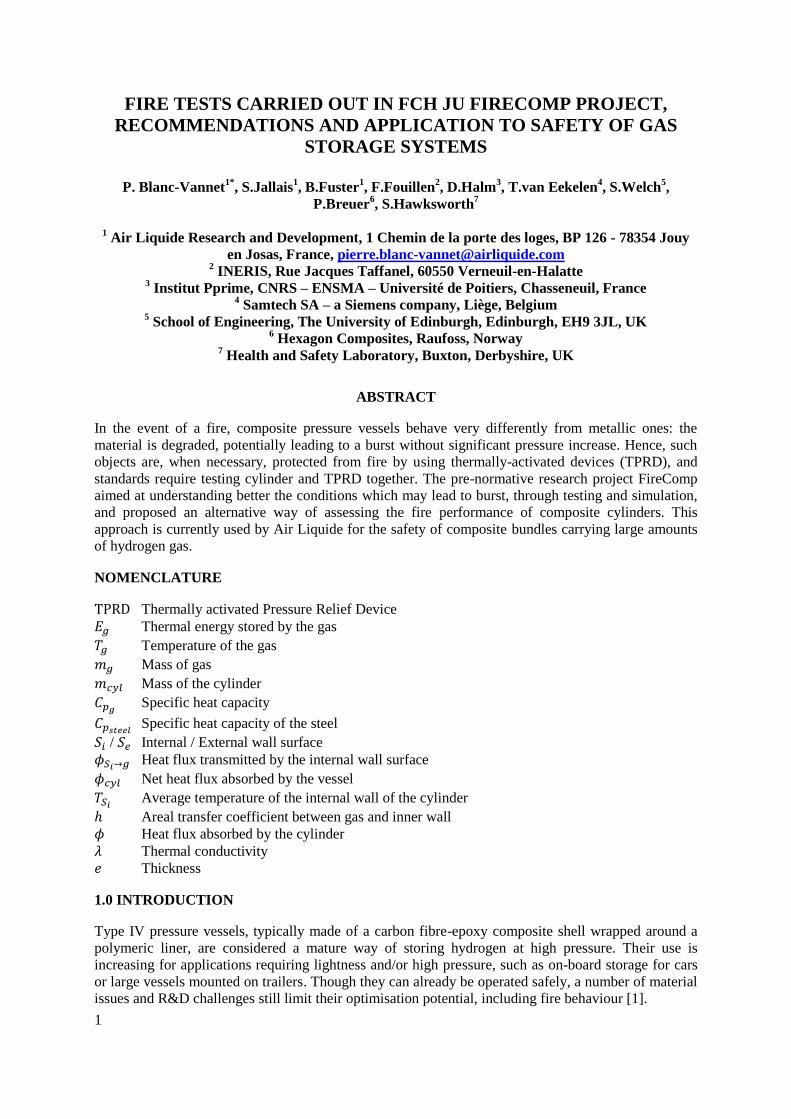
In order to increase the amount of energy that can be transmitted to the cylinder during gas fires, and
improve the homogeneity of the thermal aggression around it, a confinement is placed above the steel
cylinder. The material used to make this confinement is standard aerated concrete. Since the tests can
be done with cylinders of various dimensions (19 L & 36 L were used), the geometrical definition of
the confinement is located relative to the external walls of the cylinder. This approach allows complete
definition of the confinement, regardless of the size of the tested cylinder. A picture of the
experimental setup is displayed in Fig. 1.
The cylinder is exposed to fire by the means of four injectors. They are symmetrically located under
the cylinder as presented in Fig. 1. This position guarantees a satisfactory engulfment of the cylinder.
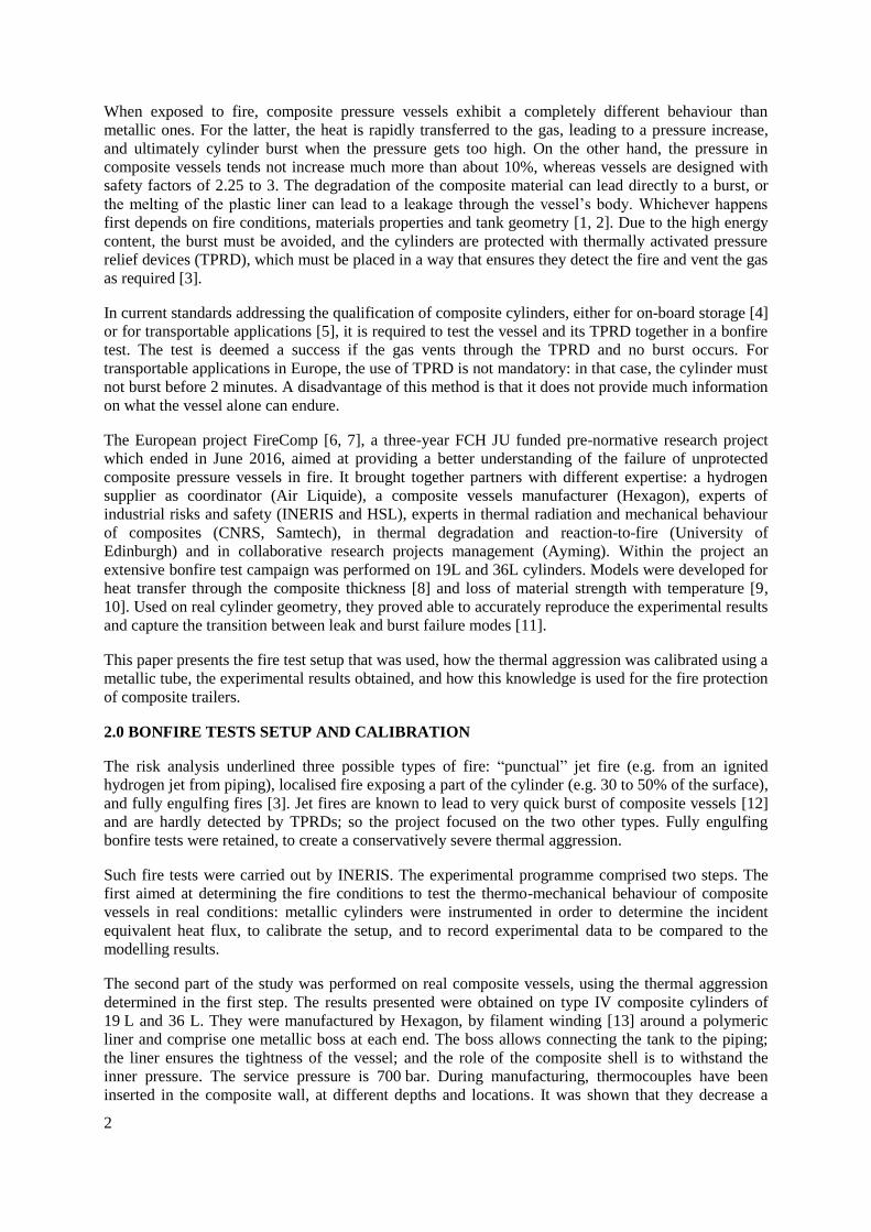
On each injector, a calibrated flow rate of hydrogen and oxygen mixture can be controlled. The
different elements implemented are presented in Fig. 2. The red parts are the elements where the
injection of oxygen is performed on each injector. The hydrogen gas fire tests are carried out with
1.5 g/s hydrogen and 0.5 g/s oxygen flow rates per injector.
(a) (b)
Figure 1. (a) Definition of the confinement (in cm) (b) Steel cylinder with confinement and gas
injectors
4
Figure 2. Definition of gas injection circuit
2.2 Calibration of thermal aggression
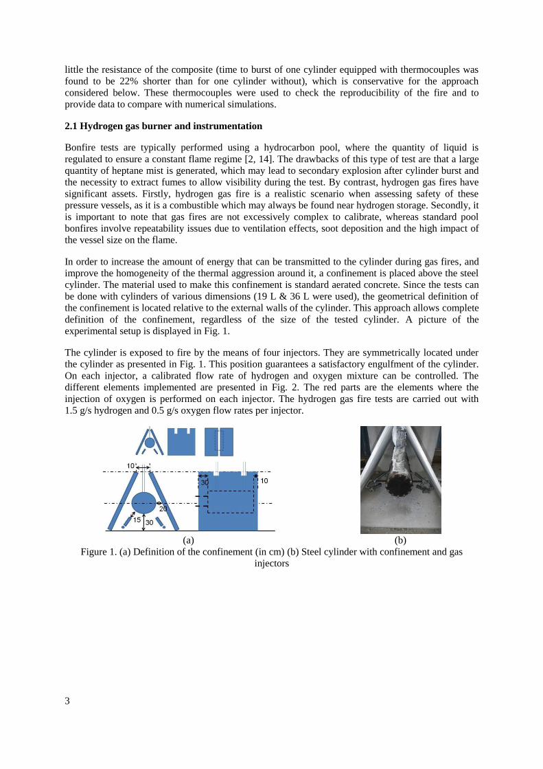
Preliminary tests were performed using a steel cylinder in order to calibrate the heat load measurement
method and study the reproducibility of the fire. Thanks to the use of metallic vessels in this
preliminary study, there are no issues related to thermal decomposition of the specimen and the
thermal properties are well known. The external dimensions of the steel cylinder are the same as those
of the 36 L composite cylinders provided by Hexagon. The sealing of the cylinders is ensured by
copper seals, to enable pressure measurements. The weight of the metallic cylinder is about 196 kg. In
addition to the pressure measurement, the evolution of temperature is recorded by 24 thermocouples
marked by red points in Fig. 3:
- 8 on the internal face of the cylinder,
- 8 on the external face of the cylinder,
- 8 in the flame region.
Figure 3. Thermocouples placed inside and around the steel cylinder used for fire calibration
The evolution of the temperature inside the vessel allows determining the net heat flux absorbed by the
mock-up, which behaves like a calorimeter. By differentiating the thermal energy stored by the gas ,
which can be calculated thanks to the measured temperature of the gas , the mass of gas , and its
specific heat capacity , it is possible to calculate the heat flux transmitted by the internal
wall surface :
(1)
with
(2)
5
It is then possible to estimate the average temperature of the internal wall of the cylinder, provided
the areal transfer coefficient does not vary appreciably during the test. This coefficient can be
estimated at about 4.4 kW/m²/K.
(3)
The thermal gradient in the thickness of the vessel wall is calculated thanks to the heat flux
absorbed by the cylinder, its thermal conductivity (32 W/m/K at 1 000°C) and its thickness :
(4)
Even if the cylinder is assumed to absorb the totality of the heat flux of the gas fire, the thermal
gradient in the thickness of the wall remains at a low value of 70°C compared to the evolution of the
internal wall temperature, which is about 650°C. It is then acceptable to consider that the temperature
is constant in the thickness of the cylinder wall, and is equal to the internal wall surface temperature.
Thanks to this assumption, the net heat flux absorbed by the vessel can then be calculated thanks
to the evolution of the internal wall surface temperature , the cylinder mass , its external
surface and its specific heat capacity .
(5)
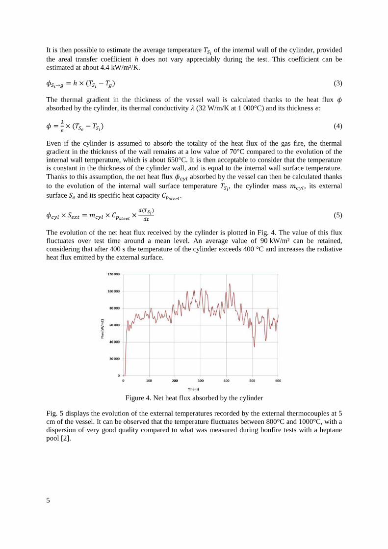
The evolution of the net heat flux received by the cylinder is plotted in Fig. 4. The value of this flux
fluctuates over test time around a mean level. An average value of 90 kW/m² can be retained,
considering that after 400 s the temperature of the cylinder exceeds 400 °C and increases the radiative
heat flux emitted by the external surface.
Figure 4. Net heat flux absorbed by the cylinder
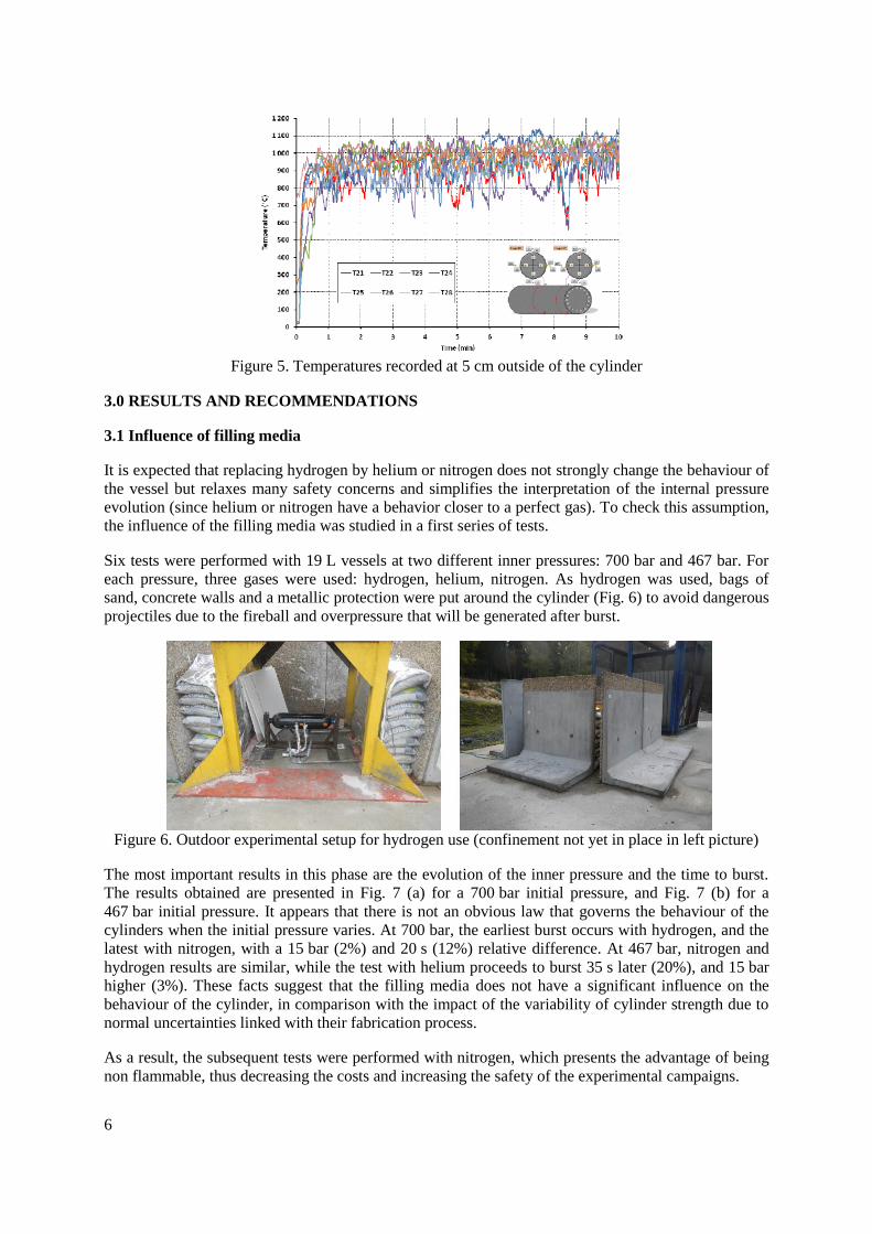
Fig. 5 displays the evolution of the external temperatures recorded by the external thermocouples at 5
cm of the vessel. It can be observed that the temperature fluctuates between 800°C and 1000°C, with a
dispersion of very good quality compared to what was measured during bonfire tests with a heptane
pool [2].
6
Figure 5. Temperatures recorded at 5 cm outside of the cylinder
3.0 RESULTS AND RECOMMENDATIONS
3.1 Influence of filling media
It is expected that replacing hydrogen by helium or nitrogen does not strongly change the behaviour of
the vessel but relaxes many safety concerns and simplifies the interpretation of the internal pressure
evolution (since helium or nitrogen have a behavior closer to a perfect gas). To check this assumption,
the influence of the filling media was studied in a first series of tests.
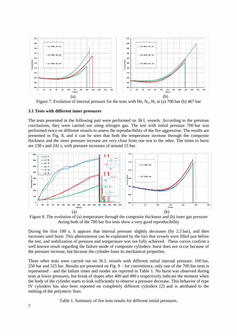
Six tests were performed with 19 L vessels at two different inner pressures: 700 bar and 467 bar. For
each pressure, three gases were used: hydrogen, helium, nitrogen. As hydrogen was used, bags of
sand, concrete walls and a metallic protection were put around the cylinder (Fig. 6) to avoid dangerous
projectiles due to the fireball and overpressure that will be generated after burst.
Figure 6. Outdoor experimental setup for hydrogen use (confinement not yet in place in left picture)
The most important results in this phase are the evolution of the inner pressure and the time to burst.
The results obtained are presented in Fig. 7 (a) for a 700 bar initial pressure, and Fig. 7 (b) for a
467 bar initial pressure. It appears that there is not an obvious law that governs the behaviour of the
cylinders when the initial pressure varies. At 700 bar, the earliest burst occurs with hydrogen, and the
latest with nitrogen, with a 15 bar (2%) and 20 s (12%) relative difference. At 467 bar, nitrogen and
hydrogen results are similar, while the test with helium proceeds to burst 35 s later (20%), and 15 bar
higher (3%). These facts suggest that the filling media does not have a significant influence on the
behaviour of the cylinder, in comparison with the impact of the variability of cylinder strength due to
normal uncertainties linked with their fabrication process.
As a result, the subsequent tests were performed with nitrogen, which presents the advantage of being
non flammable, thus decreasing the costs and increasing the safety of the experimental campaigns.
7
(a) (b)
Figure 7. Evolution of internal pressure for the tests with He, N2, H2 at (a) 700 bar (b) 467 bar
3.1 Tests with different inner pressures
The tests presented in the following part were performed on 36 L vessels. According to the previous
conclusions, they were carried out using nitrogen gas. The test with initial pressure 700 bar was
performed twice on different vessels to assess the reproducibility of the fire aggression. The results are
presented in Fig. 8, and it can be seen that both the temperature increase through the composite
thickness and the inner pressure increase are very close from one test to the other. The times to burst
are 238 s and 241 s, with pressure increases of around 15 bar.
(a) (b)
Figure 8. The evolution of (a) temperature through the composite thickness and (b) inner gas pressure
during both of the 700 bar fire tests show a very good reproducibility
During the first 100 s, it appears that internal pressure slightly decreases (by 2.5 bar), and then
increases until burst. This phenomenon can be explained by the fact that vessels were filled just before
the test, and stabilization of pressure and temperature was not fully achieved. These curves confirm a
well known result regarding the failure mode of composite cylinders: burst does not occur because of
the pressure increase, but because the cylinder loses its mechanical properties.
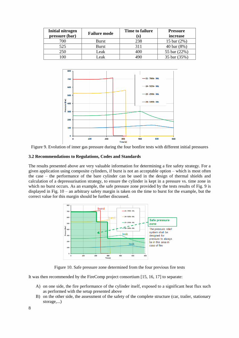
Three other tests were carried out on 36 L vessels with different initial internal pressure: 100 bar,
250 bar and 525 bar. Results are presented on Fig. 9 – for convenience, only one of the 700 bar tests is
represented – and the failure times and modes are reported in Table 1. No burst was observed during
tests at lower pressures, but break of slopes after 400 and 490 s respectively indicate the moment when
the body of the cylinder starts to leak sufficiently to observe a pressure decrease. This behavior of type
IV cylinders has also been reported on completely different cylinders [2] and is attributed to the
melting of the polymeric liner.
Table 1. Summary of fire tests results for different initial pressures.
8
Initial nitrogen
pressure (bar) Failure mode
Time to failure
(s)
Pressure
increase
700 Burst 238 15 bar (2%)
525 Burst 311 40 bar (8%)
250 Leak 400 55 bar (22%)
100 Leak 490 35 bar (35%)
Figure 9. Evolution of inner gas pressure during the four bonfire tests with different initial pressures
3.2 Recommendations to Regulations, Codes and Standards
The results presented above are very valuable information for determining a fire safety strategy. For a
given application using composite cylinders, if burst is not an acceptable option – which is most often
the case – the performance of the bare cylinder can be used in the design of thermal shields and
calculation of a depressurisation strategy, to ensure the cylinder is kept in a pressure vs. time zone in
which no burst occurs. As an example, the safe pressure zone provided by the tests results of Fig. 9 is
displayed in Fig. 10 – an arbitrary safety margin is taken on the time to burst for the example, but the
correct value for this margin should be further discussed.
Figure 10. Safe pressure zone determined from the four previous fire tests
It was then recommended by the FireComp project consortium [15, 16, 17] to separate:
A) on one side, the fire performance of the cylinder itself, exposed to a significant heat flux such
as performed with the setup presented above
B) on the other side, the assessment of the safety of the complete structure (car, trailer, stationary
storage,...)
9
The goal of test A) is to provide the cylinder user with the most reliable information of what the
cylinder can endure. As illustrated above, it can be achieved with fire tests at different initial
pressures; but this presents the drawback of a very high cost due to multiple expensive tests. An
alternative can be considered using only one cylinder and a controlled emptying. Within FireComp,
partners Samtech and CNRS developed models, with thermal properties from University of Edinburgh
tests, which proved able to accurately reproduce the time to failure and to accurately capture the
transition between burst and leak modes, if the materials, geometry and stacking sequence of the
cylinder are known.
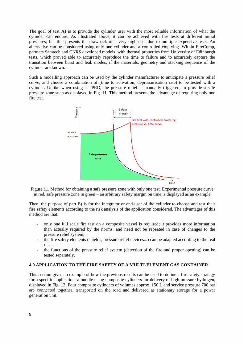
Such a modelling approach can be used by the cylinder manufacturer to anticipate a pressure relief
curve, and choose a combination of (time to activation; depressurisation rate) to be tested with a
cylinder. Unlike when using a TPRD, the pressure relief is manually triggered, to provide a safe
pressure zone such as displayed in Fig. 11. This method presents the advantage of requiring only one
fire test.
Figure 11. Method for obtaining a safe pressure zone with only one test. Experimental pressure curve
in red, safe pressure zone in green – an arbitrary safety margin on time is displayed as an example
Then, the purpose of part B) is for the integrator or end-user of the cylinder to choose and test their
fire safety elements according to the risk analysis of the application considered. The advantages of this
method are that:
- only one full scale fire test on a composite vessel is required; it provides more information
than actually required by the norms; and need not be repeated in case of changes to the
pressure relief system,
- the fire safety elements (shields, pressure relief devices...) can be adapted according to the real
risks,
- the functions of the pressure relief system (detection of the fire and proper opening) can be
tested separately.
4.0 APPLICATION TO THE FIRE SAFETY OF A MULTI-ELEMENT GAS CONTAINER
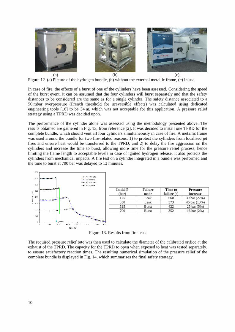
This section gives an example of how the previous results can be used to define a fire safety strategy
for a specific application: a bundle using composite cylinders for delivery of high pressure hydrogen,
displayed in Fig. 12. Four composite cylinders of volumes approx. 150 L and service pressure 700 bar
are connected together, transported on the road and delivered as stationary storage for a power
generation unit.
10
(a) (b) (c)
Figure 12. (a) Picture of the hydrogen bundle, (b) without the external metallic frame, (c) in use
In case of fire, the effects of a burst of one of the cylinders have been assessed. Considering the speed
of the burst event, it can be assumed that the four cylinders will burst separately and that the safety
distances to be considered are the same as for a single cylinder. The safety distance associated to a
50 mbar overpressure (French threshold for irreversible effects) was calculated using dedicated
engineering tools [18] to be 34 m, which was not acceptable for this application. A pressure relief
strategy using a TPRD was decided upon.
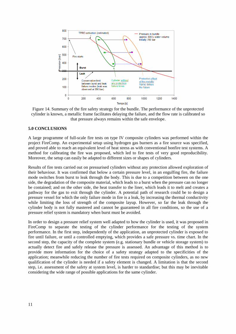
The performance of the cylinder alone was assessed using the methodology presented above. The
results obtained are gathered in Fig. 13, from reference [2]. It was decided to install one TPRD for the
complete bundle, which should vent all four cylinders simultaneously in case of fire. A metallic frame
was used around the bundle for two fire-related reasons: 1) to protect the cylinders from localised jet
fires and ensure heat would be transferred to the TPRD, and 2) to delay the fire aggression on the
cylinders and increase the time to burst, allowing more time for the pressure relief process, hence
limiting the flame length to acceptable levels in case of ignited hydrogen release. It also protects the
cylinders from mechanical impacts. A fire test on a cylinder integrated in a bundle was performed and
the time to burst at 700 bar was delayed to 13 minutes.
Initial P
(bar)
Failure
mode
Time to
failure (s)
Pressure
increase
175 Leak 660 39 bar (22%)
350 Leak 573 46 bar (13%)
525 Burst 422 25 bar (5%)
700 Burst 352 16 bar (2%)
Figure 13. Results from fire tests
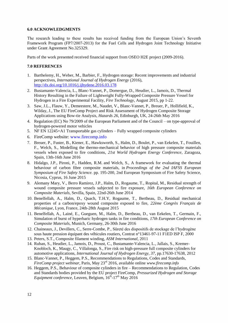
The required pressure relief rate was then used to calculate the diameter of the calibrated orifice at the
exhaust of the TPRD. The capacity for the TPRD to open when exposed to heat was tested separately,
to ensure satisfactory reaction times. The resulting numerical simulation of the pressure relief of the
complete bundle is displayed in Fig. 14, which summarises the final safety strategy.
11
Figure 14. Summary of the fire safety strategy for the bundle. The performance of the unprotected
cylinder is known, a metallic frame facilitates delaying the failure, and the flow rate is calibrated so
that pressure always remains within the safe envelope.
5.0 CONCLUSIONS
A large programme of full-scale fire tests on type IV composite cylinders was performed within the
project FireComp. An experimental setup using hydrogen gas burners as a fire source was specified,
and proved able to reach an equivalent level of heat stress as with conventional bonfire test systems. A
method for calibrating the fire was proposed, which led to fire tests of very good reproducibility.
Moreover, the setup can easily be adapted to different sizes or shapes of cylinders.
Results of fire tests carried out on pressurised cylinders without any protection allowed exploration of
their behaviour. It was confirmed that below a certain pressure level, in an engulfing fire, the failure
mode switches from burst to leak through the body. This is due to a competition between on the one
side, the degradation of the composite material, which leads to a burst when the pressure can no longer
be contained; and on the other side, the heat transfer to the liner, which leads it to melt and creates a
pathway for the gas to exit through the cylinder. A potential path of research could be to design a
pressure vessel for which the only failure mode in fire is a leak, by increasing the thermal conductivity
while limiting the loss of strength of the composite layup. However, so far the leak through the
cylinder body is not fully mastered and cannot be guaranteed in all fire conditions, so the use of a
pressure relief system is mandatory when burst must be avoided.
In order to design a pressure relief system well adapted to how the cylinder is used, it was proposed in
FireComp to separate the testing of the cylinder performance for the testing of the system
performance. In the first step, independently of the application, an unprotected cylinder is exposed to
fire until failure, or until a controlled emptying, which provides a safe pressure vs. time chart. In the
second step, the capacity of the complete system (e.g. stationary bundle or vehicle storage system) to
actually detect fire and safely release the pressure is assessed. An advantage of this method is to
provide more information for the choice of a safety strategy adapted to the specificities of the
application; meanwhile reducing the number of fire tests required on composite cylinders, as no new
qualification of the cylinder is needed if a safety element is changed. A limitation is that the second
step, i.e. assessment of the safety at system level, is harder to standardise; but this may be inevitable
considering the wide range of possible applications for the same cylinder.
12
6.0 ACKNOWLEDGMENTS
The research leading to these results has received funding from the European Union’s Seventh
Framework Program (FP7/2007-2013) for the Fuel Cells and Hydrogen Joint Technology Initiative
under Grant Agreement No.325329.
Parts of the work presented received financial support from OSEO H2E project (2009-2016).
7.0 REFERENCES
1. Barthelemy, H., Weber, M., Barbier, F., Hydrogen storage: Recent improvements and industrial
perspectives, International Journal of Hydrogen Energy (2016),
http://dx.doi.org/10.1016/j.ijhydene.2016.03.178
2. Bustamante-Valencia, L., Blanc-Vannet, P., Domergue, D., Heudier, L., Jamois, D., Thermal
History Resulting in the Failure of Lightweight Fully-Wrapped Composite Pressure Vessel for
Hydrogen in a Fire Experimental Facility, Fire Technology, August 2015, pp 1-22.
3. Saw, J.L., Flauw, Y., Demeestere, M., Naudet, V., Blanc-Vannet, P., Breuer, P., Hollifield, K.,
Wilday, J., The EU FireComp Project and Risk Assessment of Hydrogen Composite Storage
Applications using Bow-tie Analysis, Hazards 26, Edinburgh, UK, 24-26th May 2016
4. Regulation (EC) No 79/2009 of the European Parliament and of the Council – on type-approval of
hydrogen-powered motor vehicles
5. NF EN 12245+A1 Transportable gas cylinders – Fully wrapped composite cylinders
6. FireComp website: www.firecomp.info
7. Breuer, P., Fuster, B., Kiener, E., Hawksworth, S., Halm, D., Boulet, P., van Eekelen, T., Fouillen,
F., Welch, S., Modelling the thermo-mechanical behavior of high pressure composite materials
vessels when exposed to fire conditions, 21st World Hydrogen Energy Conference, Zaragoza,
Spain, 13th-16th June 2016
8. Hidalgo, J.P., Pironi, P., Hadden, R.M. and Welch, S., A framework for evaluating the thermal
behaviour of carbon fibre composite materials, in Proceedings of the 2nd IAFSS European
Symposium of Fire Safety Science. pp. 195-200, 2nd European Symposium of Fire Safety Science,
Nicosia, Cyprus, 16 June 2015
9. Alemany Mary, V., Berro Ramirez, J.P., Halm, D., Rogaume, T., Ropital, M., Residual strength of
wound composite pressure vessels subjected to fire exposure, 16th European Conference on
Composite Materials, Sevilla, Spain, 22nd-26th June 2014
10. Benelfellah, A., Halm, D., Quach, T.H.Y, Rogaume, T., Bertheau, D., Residual mechanical
properties of a carbon/epoxy wound composite exposed to fire, 22ème Congrès Français de
Mécanique, Lyon, France, 24th-28th August 2015
11. Benelfellah, A., Lainé, E., Gueguen, M., Halm, D., Bertheau, D., van Eekelen, T., Germain, F.,
Simulation of burst of hyperbaric hydrogen tanks in fire conditions, 17th European Conference on
Composite Materials, Munich, Germany, 26-30th June 2016
12. Chaineaux, J., Devillers, C., Serre-Combe, P., Sûreté des dispositifs de stockage de l’hydrogène
sous haute pression équipant des véhicules routiers, Contrat n°13461-97-11 F1ED ISP F, 2000
13. Peters, S.T., Composite filament winding, ASM International, 2011
14. Ruban, S., Heudier, L., Jamois, D., Proust, C., Bustamante-Valencia, L., Jallais, S., Kremer-
Knobloch, K., Maugy, C., Villalonga, S., Fire risk on high-pressure full composite cylinders for
automotive applications, International Journal of Hydrogen Energy, 37, pp.17630-17638, 2012
15. Blanc-Vannet, P., Heggem, P.S., Recommendations to Regulations, Codes and Standards,
FireComp project webinar, Paris, May 23rd
2016, available online www.firecomp.info
16. Heggem, P.S., Behaviour of composite cylinders in fire – Recommendations to Regulation, Codes
and Standards bodies provided by the EU project FireComp, Pressurized Hydrogen and Storage
Equipment conference, Leuven, Belgium, 16th-17
th May 2016

13
17. Heggem, P.S., Industrial perspective on fire safety of composite cylinders in hydrogen
applications, Proc. Hydrogen Bridge: Safety of High-Pressure Hydrogen Storage, Hangzhou,
China, 2016
18. Houssin-Agbomson, D., Jallais, S., Développement d’outils d’ingénieurs pour l’évaluation du
risque hydrogène. Lecture, Lambda Mu Conference, St-Malo, France, 11th-13
th Oct. 2016.