Embed Size (px)
Citation preview
Final Report
CATION, 7FP FCH JU project no. 256627 1
PROJECT FINAL REPORT
Publishable Summary
FCH JU Grant Agreement number: 256627
Project acronym: CATION
Project title: Cathode Sub-System Development and Optimisation
Funding Scheme:
Period covered: from 01/01/2011 to 30/06/2014
Name of the scientific representative of the project's co-ordinator, Title and Organisation:
Jari Kiviaho, Dr., VTT Technical Research Centre of Finland
Tel: +358 20 722 5298
Fax: +358 20 722 7048
E-mail: [email protected]
Project website address: http://cation.vtt.fi/
Final Report
CATION, 7FP FCH JU project no. 256627 2
European Commission 7th Framework Programme
Project no. 256627
Cathode Subsystem Development and Optimisation Project acronym: CATION
Public website
http://cation.vtt.fi/
Contact information
Dr. Jari Kiviaho
Coordinator
VTT Technical Research Centre of Finland
+358 50 5116778
Partners
AVL LIST GMBH MartinHauth,
TOPSOE FUEL CELL AB Søren Bay,
BOSAL RESEARCH NV Yves De Vos,
UNIVERSITA DEGLI STUDI DI GENOVA Carlo Strazza,
Final Report
CATION, 7FP FCH JU project no. 256627 3
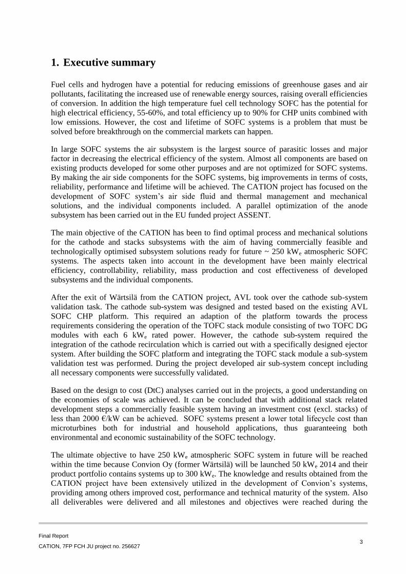
1. Executive summary
Fuel cells and hydrogen have a potential for reducing emissions of greenhouse gases and air
pollutants, facilitating the increased use of renewable energy sources, raising overall efficiencies
of conversion. In addition the high temperature fuel cell technology SOFC has the potential for
high electrical efficiency, 55-60%, and total efficiency up to 90% for CHP units combined with
low emissions. However, the cost and lifetime of SOFC systems is a problem that must be
solved before breakthrough on the commercial markets can happen.
In large SOFC systems the air subsystem is the largest source of parasitic losses and major
factor in decreasing the electrical efficiency of the system. Almost all components are based on
existing products developed for some other purposes and are not optimized for SOFC systems.
By making the air side components for the SOFC systems, big improvements in terms of costs,
reliability, performance and lifetime will be achieved. The CATION project has focused on the
development of SOFC system’s air side fluid and thermal management and mechanical
solutions, and the individual components included. A parallel optimization of the anode
subsystem has been carried out in the EU funded project ASSENT.
The main objective of the CATION has been to find optimal process and mechanical solutions
for the cathode and stacks subsystems with the aim of having commercially feasible and
technologically optimised subsystem solutions ready for future ~ 250 kWe atmospheric SOFC
systems. The aspects taken into account in the development have been mainly electrical
efficiency, controllability, reliability, mass production and cost effectiveness of developed
subsystems and the individual components.
After the exit of Wärtsilä from the CATION project, AVL took over the cathode sub-system
validation task. The cathode sub-system was designed and tested based on the existing AVL
SOFC CHP platform. This required an adaption of the platform towards the process
requirements considering the operation of the TOFC stack module consisting of two TOFC DG
modules with each 6 kWe rated power. However, the cathode sub-system required the
integration of the cathode recirculation which is carried out with a specifically designed ejector
system. After building the SOFC platform and integrating the TOFC stack module a sub-system
validation test was performed. During the project developed air sub-system concept including
all necessary components were successfully validated.
Based on the design to cost (DtC) analyses carried out in the projects, a good understanding on
the economies of scale was achieved. It can be concluded that with additional stack related
development steps a commercially feasible system having an investment cost (excl. stacks) of
less than 2000 €/kW can be achieved. SOFC systems present a lower total lifecycle cost than
microturbines both for industrial and household applications, thus guaranteeing both
environmental and economic sustainability of the SOFC technology.
The ultimate objective to have 250 kWe atmospheric SOFC system in future will be reached
within the time because Convion Oy (former Wärtsilä) will be launched 50 kWe 2014 and their
product portfolio contains systems up to 300 kWe. The knowledge and results obtained from the
CATION project have been extensively utilized in the development of Convion’s systems,
providing among others improved cost, performance and technical maturity of the system. Also
all deliverables were delivered and all milestones and objectives were reached during the
Final Report
CATION, 7FP FCH JU project no. 256627 4
project. Conclusion is that CATION project was finalised successfully.
2. Project content and main objectives
The main objective of the CATION has been to find optimal process and mechanical solutions
for the cathode and stacks subsystems with the aim of having commercially feasible and
technologically optimised subsystem solutions ready for future ~ 250 kWe atmospheric SOFC
systems. The aspects taken into account in the development have been mainly electrical
efficiency, controllability, reliability, mass production and cost effectiveness of developed
subsystems and the individual components. However, Wärtsilä terminated its fuel cell activities
and partnership in the project after mid-term review (M18). The remaining work was divided
between VTT, TOFC and AVL, AVL taking considerably more responsibility than in the
original plans. This change added project time for half a year in order for AVL to successfully
implement all components to fit their system.
In order to reach the main objectives, some sub-objectives were set and reached:
• To provide modelling input for optimal cathode subsystem layout and choosing the
best ones for further analysis including sensitivity and reliability analysis for the most
promising subsystem
• To develop components which are optimal for the cathode subsystem and to evaluate
their feasibility and manufacturing technologies
• To develop a compact and cost-effective stack module where the stack/system
interface and related solutions are optimized
• To validate overall cathode subsystem solution in real fuel cell system
The actual work of the CATION focuses on evaluating different process alternatives and
optimal process and mechanical solutions for the cathode-side subsystem and the stack/system
interface. The evaluated alternatives include among others traditional parallel single-pass air
feed to the stacks, air-in-series connection of the stacks and air recirculation. Possibilities of
combining different functions into single components, such as integrated heat exchanger-
afterburner, are also taken into account. Relevant process options were first evaluated by
conceptual system simulation, and these results were used as a basis for detailed feasibility
evaluation. The other part of the work was to develop an optimized stack-system interface. The
current stack technology is more or less optimized to be a well-performing single-stack system.
Based on the obtained results, the most suitable concept was selected for prototyping and
validation. This part includes component/subsystem prototype manufacturing and testing of the
chosen solution. For large systems, full-scale test benches were impractical to accomplish
without building a full system. Therefore, the prototype manufacturing and testing is being done
with downscaled components.
The main part of the CATION experiments and simulations focus on (1) novel designs and
optimization of non-stack components, (2) the manufacturing process and control techniques for
mature components, (3) component durability/robustness in the application environment, (4)
costs assessment vs. target costs, (5) demonstration of End of Life specifications, (6) concept for
Final Report
CATION, 7FP FCH JU project no. 256627 5
recycling and disposal of systems, including the associated costs and (7) Life Cycle Analysis
(LCA) according to developed guidelines.
Design to cost analysis (DtC) has been conducted within both projects to support the
understanding of overall commercial feasibility of different process approaches. The conducted
analyses had two different aims: to understand the economies of scale when increasing the
power output of the system, and to pin-point the relative importance of the anode side
subsystem for the overall system cost. The DtC analysis was started with evaluating the detailed
system costs based on known BoP component and solution cost behaviors as a function of scale,
and the development conducted for anode side components during ASSENT was taken into
account.
After the exit of Wärtsilä from the CATION project, AVL took over the cathode sub-system
validation task. The cathode sub-system was designed and tested based on the existing 10 kWel
AVL SOFC CHP platform which was developed in recent projects. This required an adaption of
the platform towards the process requirements considering the operation of the TOFC stack
module consisting of two TOFC DG modules with each 6 kWel rated power. The anode sub-
system could be kept similar to the existing design. However, the cathode sub-system required
the integration of the cathode recirculation which is carried out with a specifically designed
ejector system. The ejector was designed first by preliminary simulations based on the process
parameters of the cathode sub-system. From this simulation results the main geometry of the
ejector was determined. Furthermore, a polynomial function of the ejector performance was
derived to be used in the process simulation in order to consider the ejector behaviour for
process variation simulations. After freezing the process parameters the ejector performance
was validated by CFD simulations compared with the preliminary simulations. Based on the
cathode recirculation concept the packaging of the platform was adapted to integrate the ejector.
Also the interface between the BoP and the TOFC stack module had to be adapted. After
building the SOFC platform and integrating the TOFC stack module a sub-system validation
test was performed and compared with the original process simulation.
Environmental performance (LCA) comparison was built between a SOFC system with ejector-
based cathode recirculation and a gas microturbine. It was demonstrated that the studied SOFC
system is able to yield environmental benefits on the environmental load from a life cycle point
of view for all the impact categories considered with respect to the conventional technology.
This finding from the environmental point-of-view was confirmed in terms of economic
performance by the Life Cycle Cost comparison. At commercial level, it can be concluded that
SOFC systems present a lower total LCC with respect to microturbines both for industrial and
household applications, thus guaranteeing both environmental and economic sustainability.
Based on the design to cost (DtC) analyses carried out in the projects, a good understanding on
the economies of scale was achieved, and also a cost split between different (sub)functions in an
SOFC system was generated. As a result, it can be concluded that with certain additional stack
related development steps a commercially feasible system having an investment cost (excl.
stacks) of less than 2000 €/kW can be achieved. At commercial level, it can be also concluded
that SOFC systems present a lower total lifecycle cost than microturbines both for industrial and
household applications, thus guaranteeing both environmental and economic sustainability of
the SOFC technology.
Final Report
CATION, 7FP FCH JU project no. 256627 6
3. S & T results/foregrounds
3.1 System layout design
In Conceptual Evaluation of Subsystems Alternatives reported the results of modelling
seven different conceptual layouts and also resulted in reaching Milestone 1. Modelling
work was done on both system and component level and computational fluid dynamic
(CFD) modelling of the ejector was done to support the systems modelling. The results
show that using a modular stacks instead of a single stack or utilizing and ejector and air
recirculation can both improve system performance. Three burner positions were simulated
and the optimal one for current stacks determined. The characteristic advantages and
disadvantages of each layout concept were studied to determine how to proceed and a
rudimentary sensitivity analysis was done to all layouts. As a result, modular stack case and
the ejector cases were seen as the best ones and chosen for further studies.
Sensitivity and Reliability Analysis focused on sensitivity analysis of the ejector cases and
reliability analysis of all layouts. The simulation results gained with a more accurate ejector
model show that even though the ejector is quite sensitive to changes to many key
parameters, it is possible to design it appropriately so that the end result of using an ejector
is beneficial. Thus the ejector seems like a promising concept for further development. In
the reliability analysis, all of the different layout concepts of were compared to each other
by listing and ranking different risks according to their severity, safety risks being ranked
highest. The results show that using the ejector involves some additional risks compared to
the base case but on the balance the layout concept seems viable. The air in series –stack
layout involves greatly increased risks that could be alleviated with careful system design.
The results showed that modular stack case had higher risks involved than any of the other
cases, yet using careful system design it could well be viable. The ejector cases performed
well in both the risk analysis and the more accurate system simulations. As such, the results
of the conceptual study of the layout alternatives – were that both the modular stack case as
well as the ejector air recirculation seemed viable.
Summary: System layout design work has been completed according to Annex1
requirements in an excellent manner during first period. Communication between partners
and work packages worked well and the results were used directly in other development
works. All in all, this work can be considered a success and valuable information for the
other development was gained.
3.2 Component testing and cost analysis
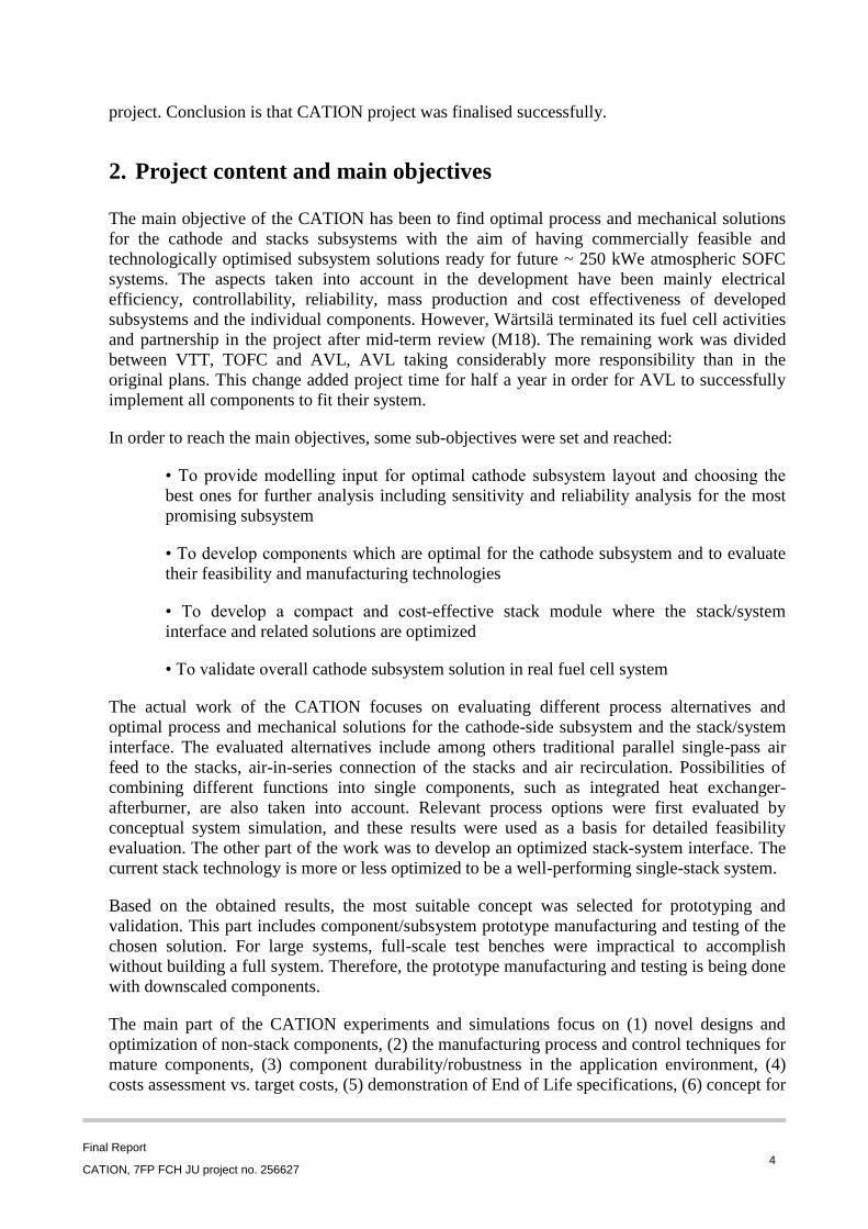
Design and Testing of ejector for AVL SOFC CHP system: The ejector was designed
based on the input parameters used as boundary conditions derived from the process
simulation in subsystem validation part of the work (See Table ):
Table 1. Design specification for cathode ejector
Final Report
CATION, 7FP FCH JU project no. 256627 7
The design was optimized to keep the pressure drop between force inlet and discharge outlet
at a minimum since this pressure drop needs to be compensated by additional blower power
compared to a system without cathode recirculation. Furthermore, it had to be checked that
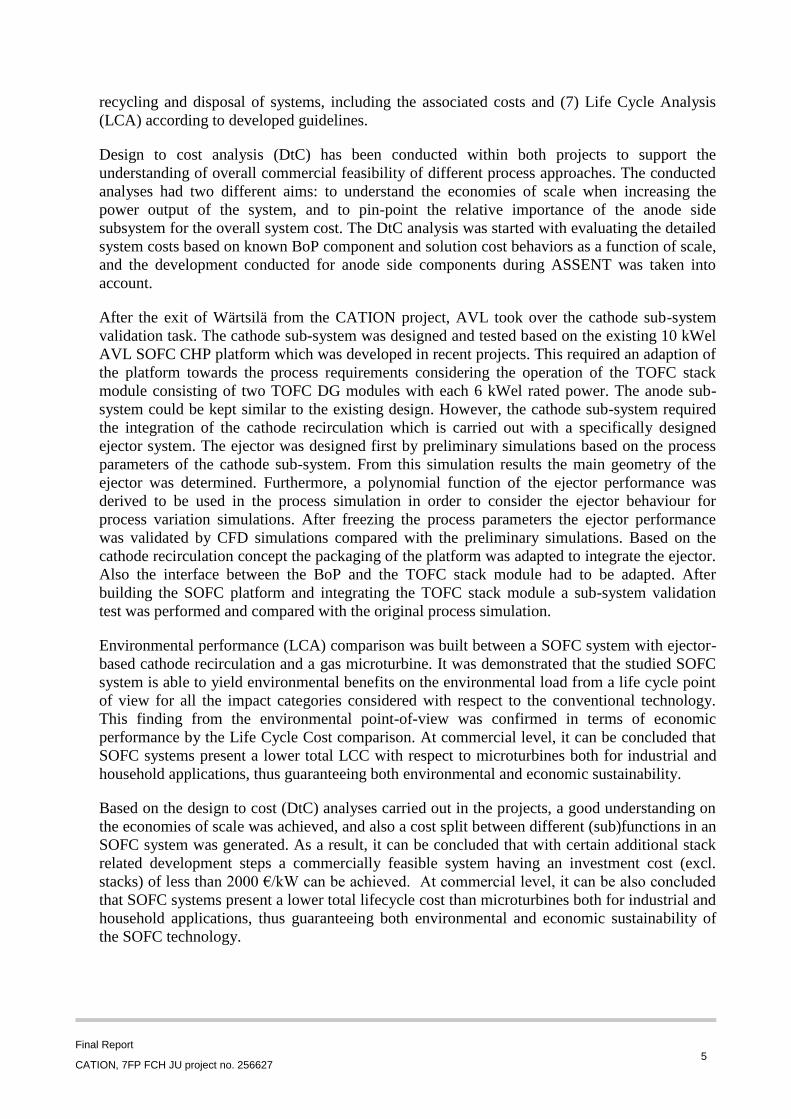
the required blower pressure is within the limits of the blower specifications. In a parameter
study the optimal ejector geometry and dimensions have been investigated. Figure shows
the resulting main dimensions of the ejector determined by preliminary calculations.
Figure 2. Main dimensions of the cathode ejector
In a second step the design was further validated by CFD simulations in AVL FIRE (AVL
CFD software product). In Table a comparison of the preliminary simulation and the CFD
simulation is shown. Both results are very close to each other which demonstrate that the
preliminary simulation is a good tool to find a proper design of the ejector and therefore
determine the main dimensions.
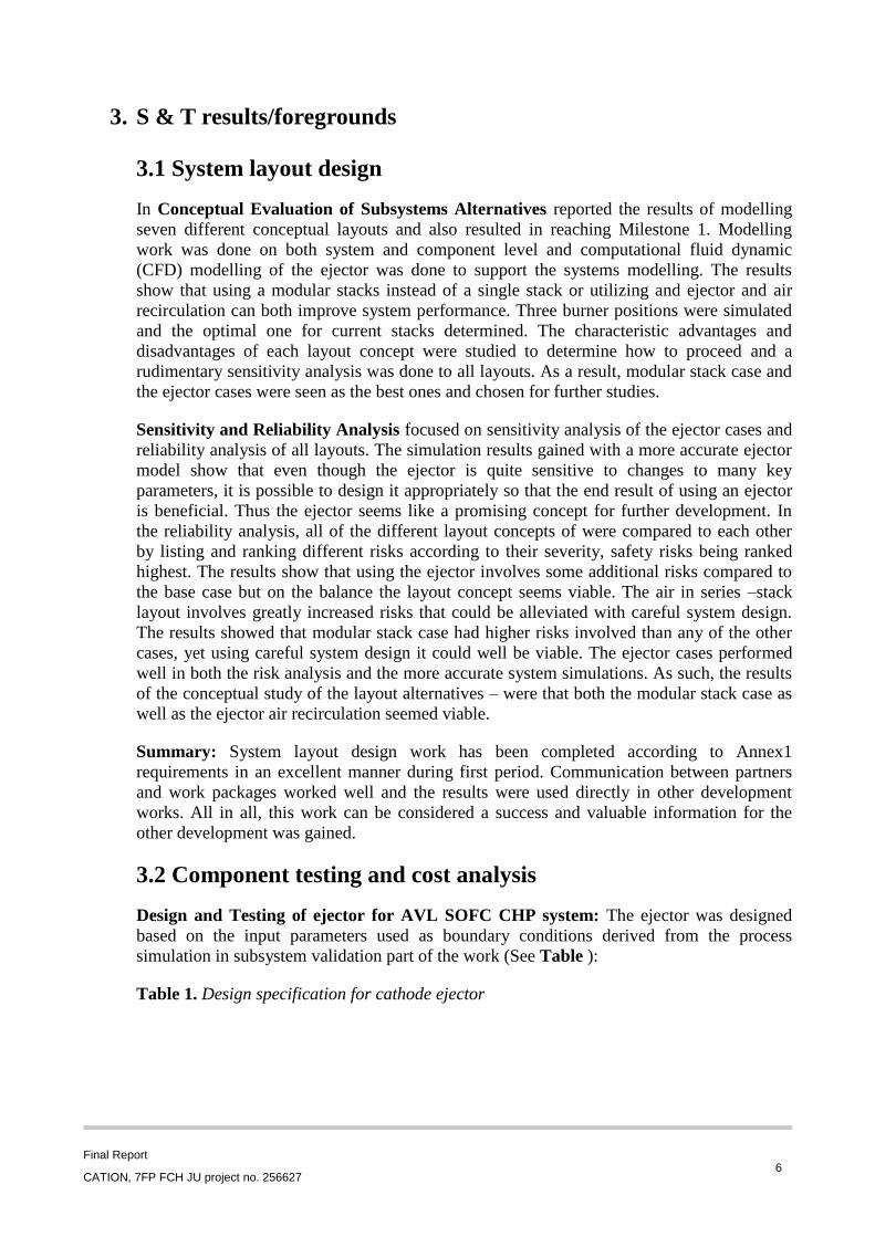
Figure shows the CFD results for the temperature and velocity profile of the ejector. It
illustrates the flow pattern within the ejector and proofs a good performance.
Final Report
CATION, 7FP FCH JU project no. 256627 8
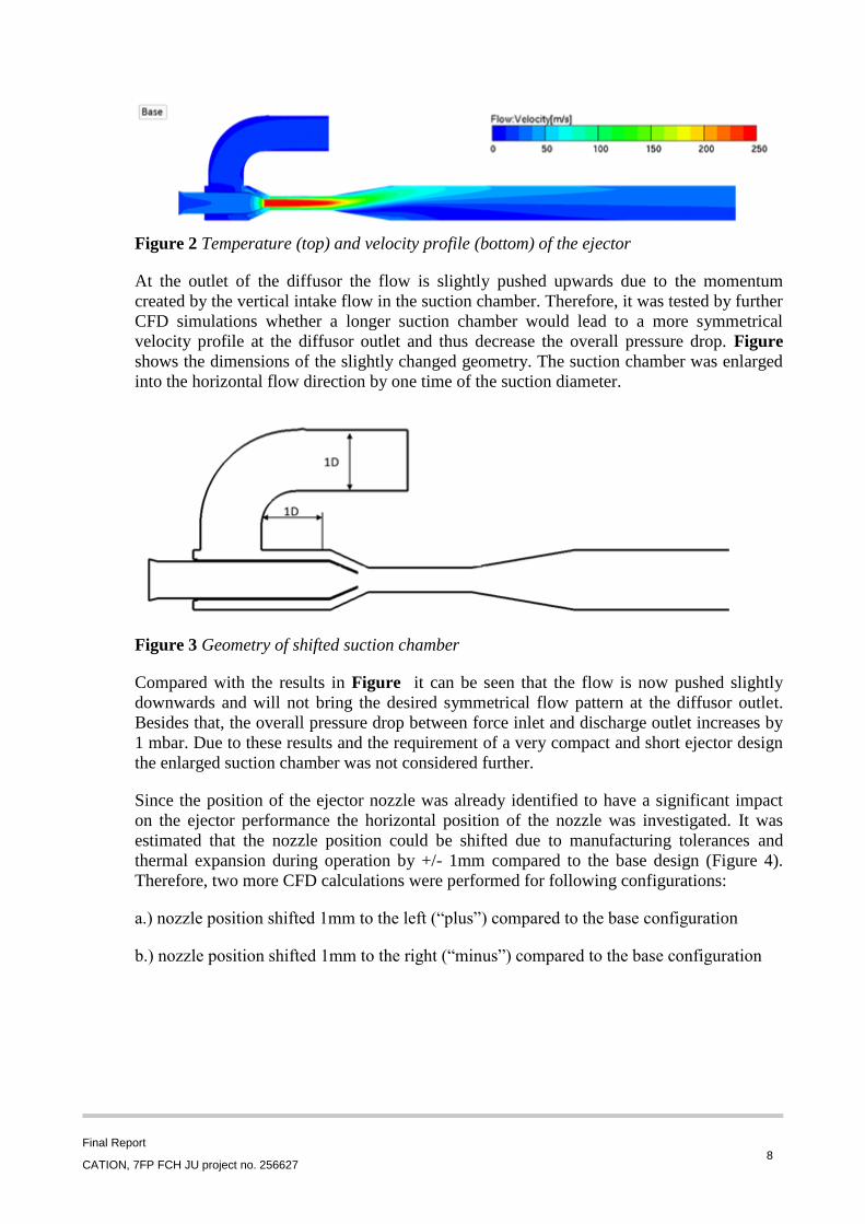
Figure 2 Temperature (top) and velocity profile (bottom) of the ejector
At the outlet of the diffusor the flow is slightly pushed upwards due to the momentum
created by the vertical intake flow in the suction chamber. Therefore, it was tested by further
CFD simulations whether a longer suction chamber would lead to a more symmetrical
velocity profile at the diffusor outlet and thus decrease the overall pressure drop. Figure
shows the dimensions of the slightly changed geometry. The suction chamber was enlarged
into the horizontal flow direction by one time of the suction diameter.
Figure 3 Geometry of shifted suction chamber
Compared with the results in Figure it can be seen that the flow is now pushed slightly
downwards and will not bring the desired symmetrical flow pattern at the diffusor outlet.
Besides that, the overall pressure drop between force inlet and discharge outlet increases by
1 mbar. Due to these results and the requirement of a very compact and short ejector design
the enlarged suction chamber was not considered further.
Since the position of the ejector nozzle was already identified to have a significant impact
on the ejector performance the horizontal position of the nozzle was investigated. It was
estimated that the nozzle position could be shifted due to manufacturing tolerances and
thermal expansion during operation by +/- 1mm compared to the base design (Figure 4).
Therefore, two more CFD calculations were performed for following configurations:
a.) nozzle position shifted 1mm to the left (“plus”) compared to the base configuration
b.) nozzle position shifted 1mm to the right (“minus”) compared to the base configuration
Final Report
CATION, 7FP FCH JU project no. 256627 9
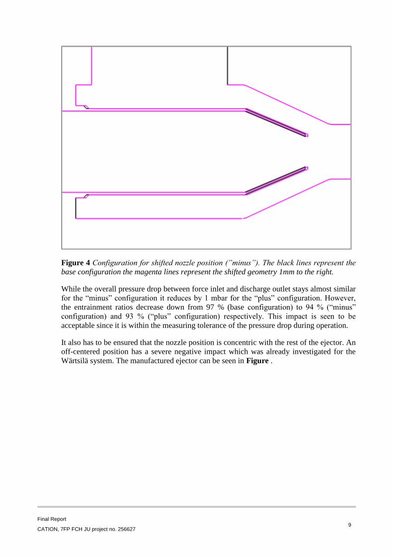
Figure 4 Configuration for shifted nozzle position (”minus”). The black lines represent the
base configuration the magenta lines represent the shifted geometry 1mm to the right.
While the overall pressure drop between force inlet and discharge outlet stays almost similar
for the “minus” configuration it reduces by 1 mbar for the “plus” configuration. However,
the entrainment ratios decrease down from 97 % (base configuration) to 94 % (“minus”
configuration) and 93 % (“plus” configuration) respectively. This impact is seen to be
acceptable since it is within the measuring tolerance of the pressure drop during operation.
It also has to be ensured that the nozzle position is concentric with the rest of the ejector. An
off-centered position has a severe negative impact which was already investigated for the
Wärtsilä system. The manufactured ejector can be seen in Figure .
Final Report
CATION, 7FP FCH JU project no. 256627 10
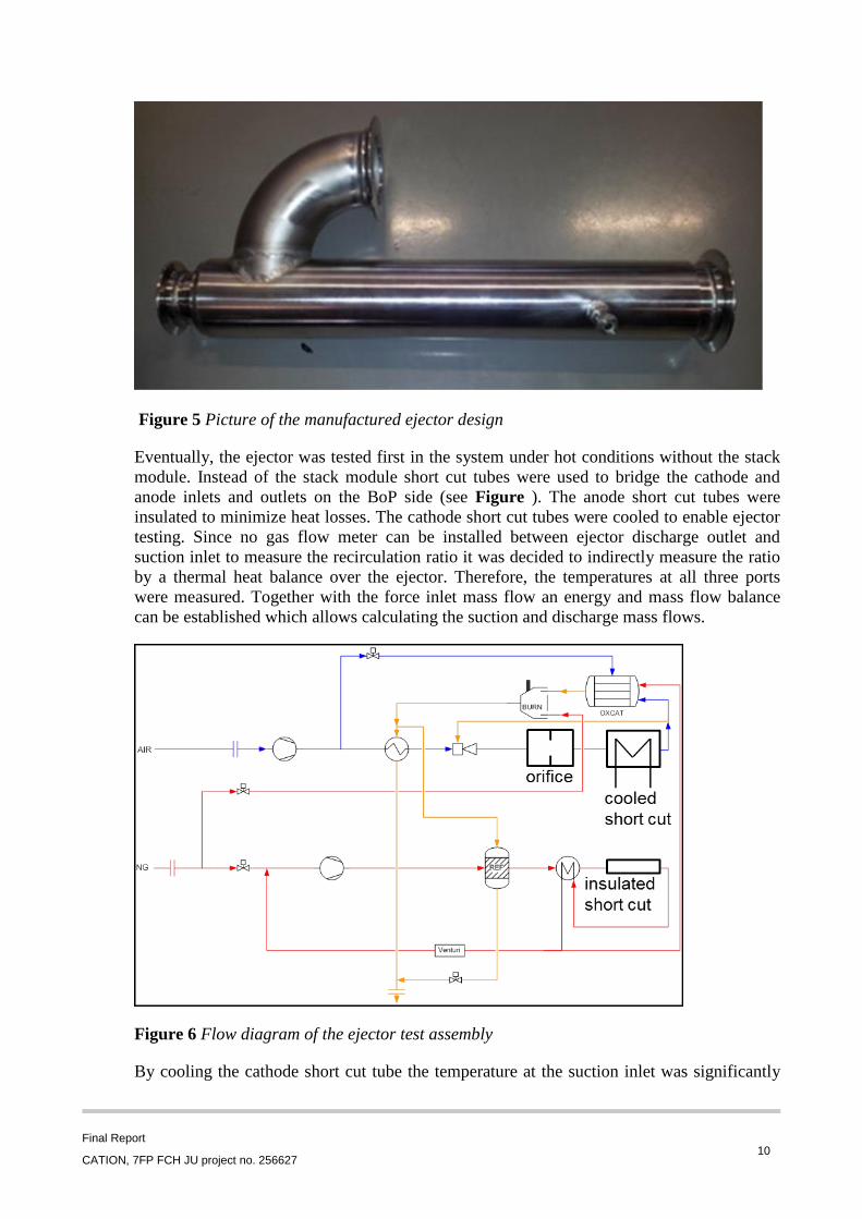
Figure 5 Picture of the manufactured ejector design
Eventually, the ejector was tested first in the system under hot conditions without the stack
module. Instead of the stack module short cut tubes were used to bridge the cathode and
anode inlets and outlets on the BoP side (see Figure ). The anode short cut tubes were
insulated to minimize heat losses. The cathode short cut tubes were cooled to enable ejector
testing. Since no gas flow meter can be installed between ejector discharge outlet and
suction inlet to measure the recirculation ratio it was decided to indirectly measure the ratio
by a thermal heat balance over the ejector. Therefore, the temperatures at all three ports
were measured. Together with the force inlet mass flow an energy and mass flow balance
can be established which allows calculating the suction and discharge mass flows.
Figure 6 Flow diagram of the ejector test assembly
By cooling the cathode short cut tube the temperature at the suction inlet was significantly
Final Report
CATION, 7FP FCH JU project no. 256627 11
colder which is favourable for the accuracy of this methodology. This technique is
considered to be not very accurate due to heat losses but nevertheless supported a
preliminary validation of the ejector before the stack module integration in terms of the
recirculation rate, the pressure levels and the air blower power. For measuring the cathode
recirculation rate during operation the oxygen concentration will be measured at the inlet of
the cathode as an additional parameter to calculate the recirculation ratio.
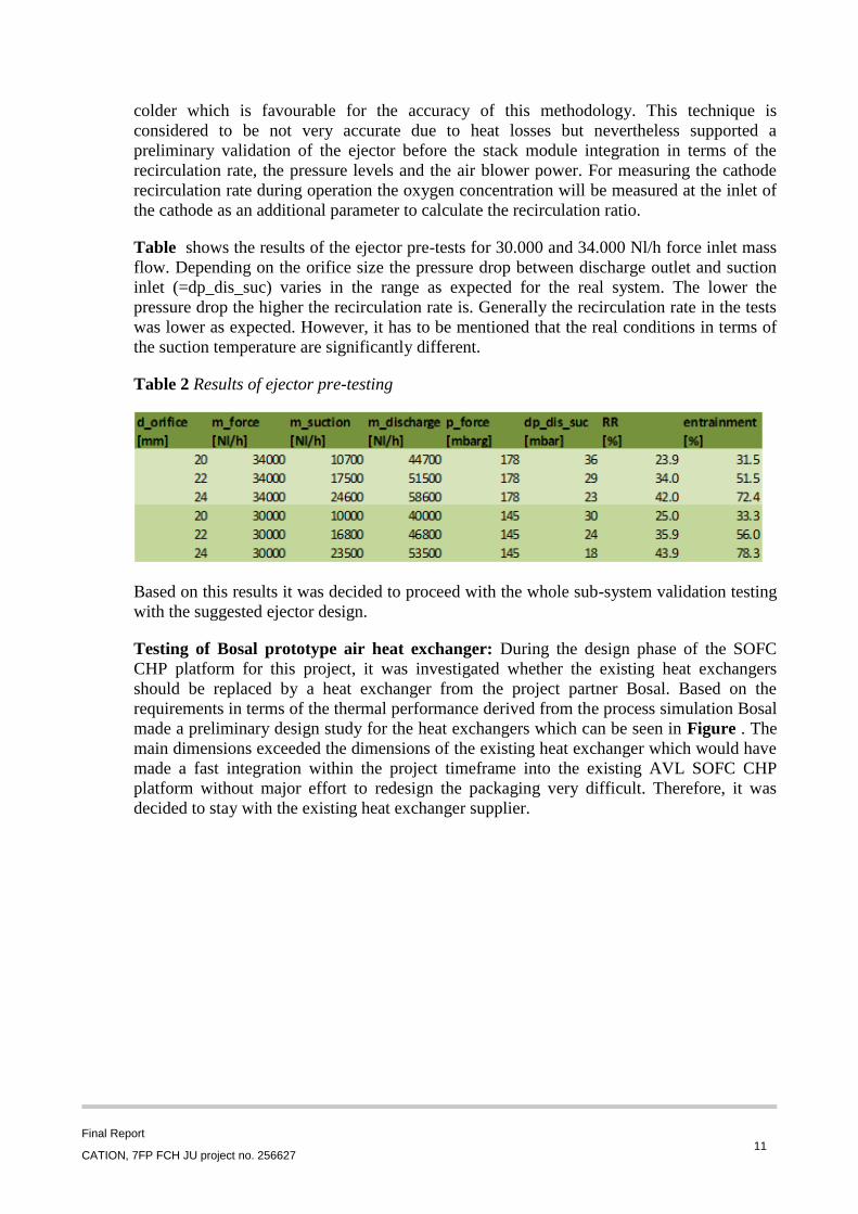
Table shows the results of the ejector pre-tests for 30.000 and 34.000 Nl/h force inlet mass
flow. Depending on the orifice size the pressure drop between discharge outlet and suction
inlet (=dp_dis_suc) varies in the range as expected for the real system. The lower the
pressure drop the higher the recirculation rate is. Generally the recirculation rate in the tests
was lower as expected. However, it has to be mentioned that the real conditions in terms of
the suction temperature are significantly different.
Table 2 Results of ejector pre-testing
Based on this results it was decided to proceed with the whole sub-system validation testing
with the suggested ejector design.
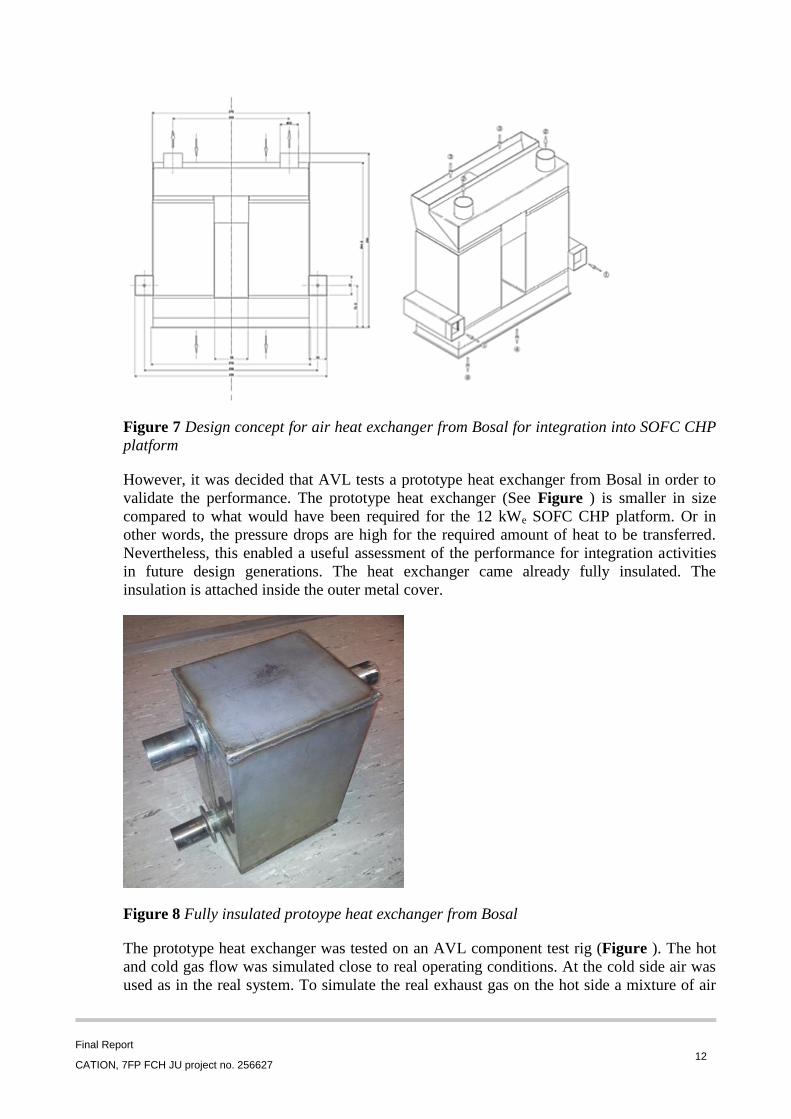
Testing of Bosal prototype air heat exchanger: During the design phase of the SOFC
CHP platform for this project, it was investigated whether the existing heat exchangers
should be replaced by a heat exchanger from the project partner Bosal. Based on the
requirements in terms of the thermal performance derived from the process simulation Bosal
made a preliminary design study for the heat exchangers which can be seen in Figure . The
main dimensions exceeded the dimensions of the existing heat exchanger which would have
made a fast integration within the project timeframe into the existing AVL SOFC CHP
platform without major effort to redesign the packaging very difficult. Therefore, it was
decided to stay with the existing heat exchanger supplier.
Final Report
CATION, 7FP FCH JU project no. 256627 12
Figure 7 Design concept for air heat exchanger from Bosal for integration into SOFC CHP
platform
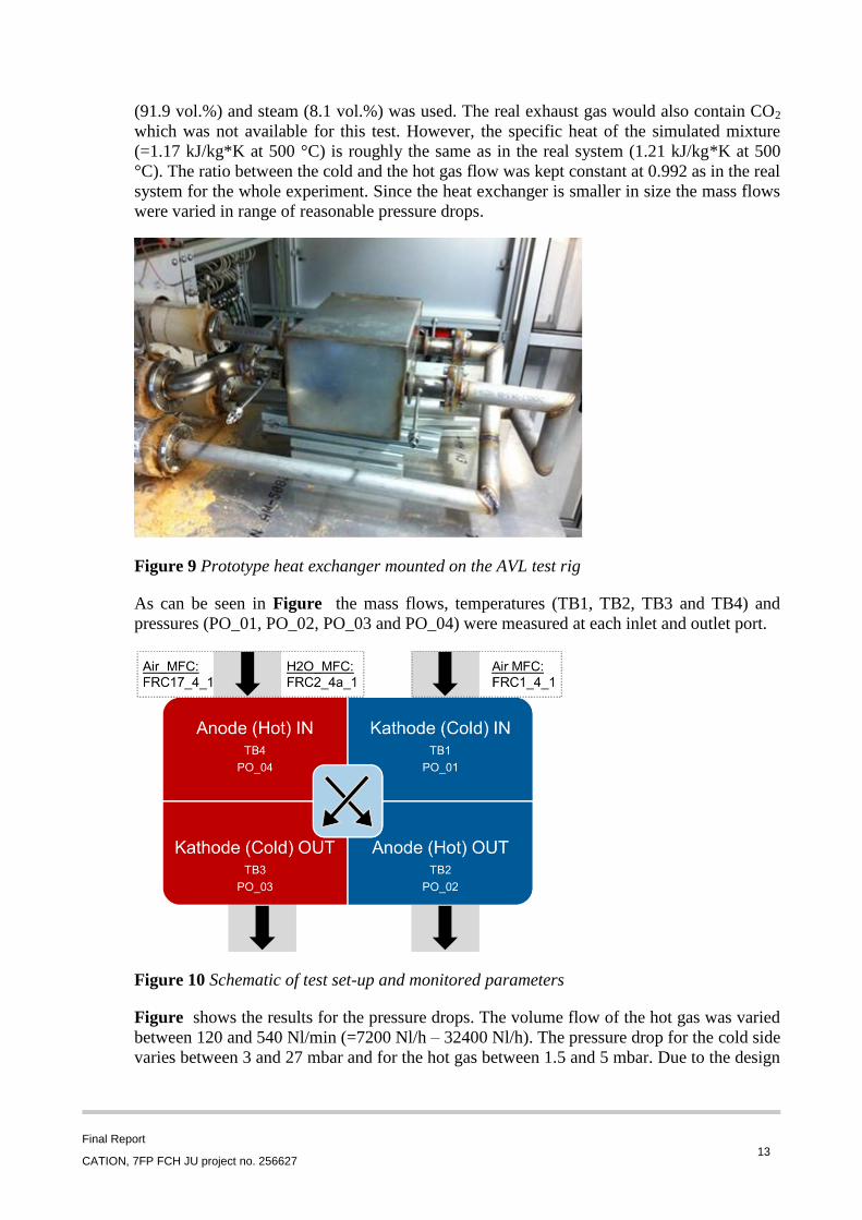
However, it was decided that AVL tests a prototype heat exchanger from Bosal in order to
validate the performance. The prototype heat exchanger (See Figure ) is smaller in size
compared to what would have been required for the 12 kWe SOFC CHP platform. Or in
other words, the pressure drops are high for the required amount of heat to be transferred.
Nevertheless, this enabled a useful assessment of the performance for integration activities
in future design generations. The heat exchanger came already fully insulated. The
insulation is attached inside the outer metal cover.
Figure 8 Fully insulated protoype heat exchanger from Bosal
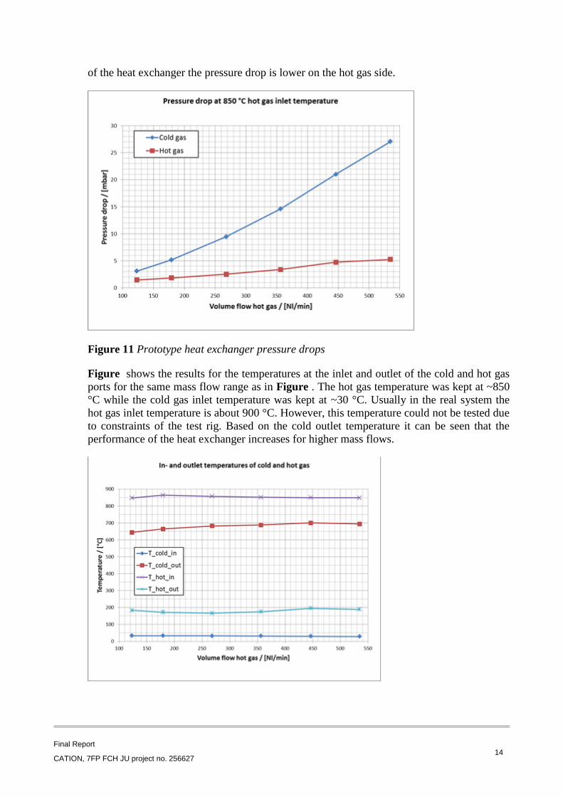
The prototype heat exchanger was tested on an AVL component test rig (Figure ). The hot
and cold gas flow was simulated close to real operating conditions. At the cold side air was
used as in the real system. To simulate the real exhaust gas on the hot side a mixture of air
Final Report
CATION, 7FP FCH JU project no. 256627 13
(91.9 vol.%) and steam (8.1 vol.%) was used. The real exhaust gas would also contain CO2
which was not available for this test. However, the specific heat of the simulated mixture
(=1.17 kJ/kg*K at 500 °C) is roughly the same as in the real system (1.21 kJ/kg*K at 500
°C). The ratio between the cold and the hot gas flow was kept constant at 0.992 as in the real
system for the whole experiment. Since the heat exchanger is smaller in size the mass flows
were varied in range of reasonable pressure drops.
Figure 9 Prototype heat exchanger mounted on the AVL test rig
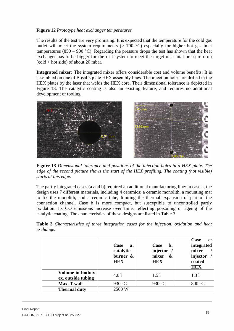
As can be seen in Figure the mass flows, temperatures (TB1, TB2, TB3 and TB4) and
pressures (PO_01, PO_02, PO_03 and PO_04) were measured at each inlet and outlet port.
Figure 10 Schematic of test set-up and monitored parameters
Figure shows the results for the pressure drops. The volume flow of the hot gas was varied
between 120 and 540 Nl/min (=7200 Nl/h – 32400 Nl/h). The pressure drop for the cold side
varies between 3 and 27 mbar and for the hot gas between 1.5 and 5 mbar. Due to the design
Final Report
CATION, 7FP FCH JU project no. 256627 14
of the heat exchanger the pressure drop is lower on the hot gas side.
Figure 11 Prototype heat exchanger pressure drops
Figure shows the results for the temperatures at the inlet and outlet of the cold and hot gas
ports for the same mass flow range as in Figure . The hot gas temperature was kept at ~850
°C while the cold gas inlet temperature was kept at ~30 °C. Usually in the real system the
hot gas inlet temperature is about 900 °C. However, this temperature could not be tested due
to constraints of the test rig. Based on the cold outlet temperature it can be seen that the
performance of the heat exchanger increases for higher mass flows.
Final Report
CATION, 7FP FCH JU project no. 256627 15
Figure 12 Prototype heat exchanger temperatures
The results of the test are very promising. It is expected that the temperature for the cold gas
outlet will meet the system requirements (> 700 °C) especially for higher hot gas inlet
temperatures (850 – 900 °C). Regarding the pressure drops the test has shown that the heat
exchanger has to be bigger for the real system to meet the target of a total pressure drop
(cold + hot side) of about 20 mbar.
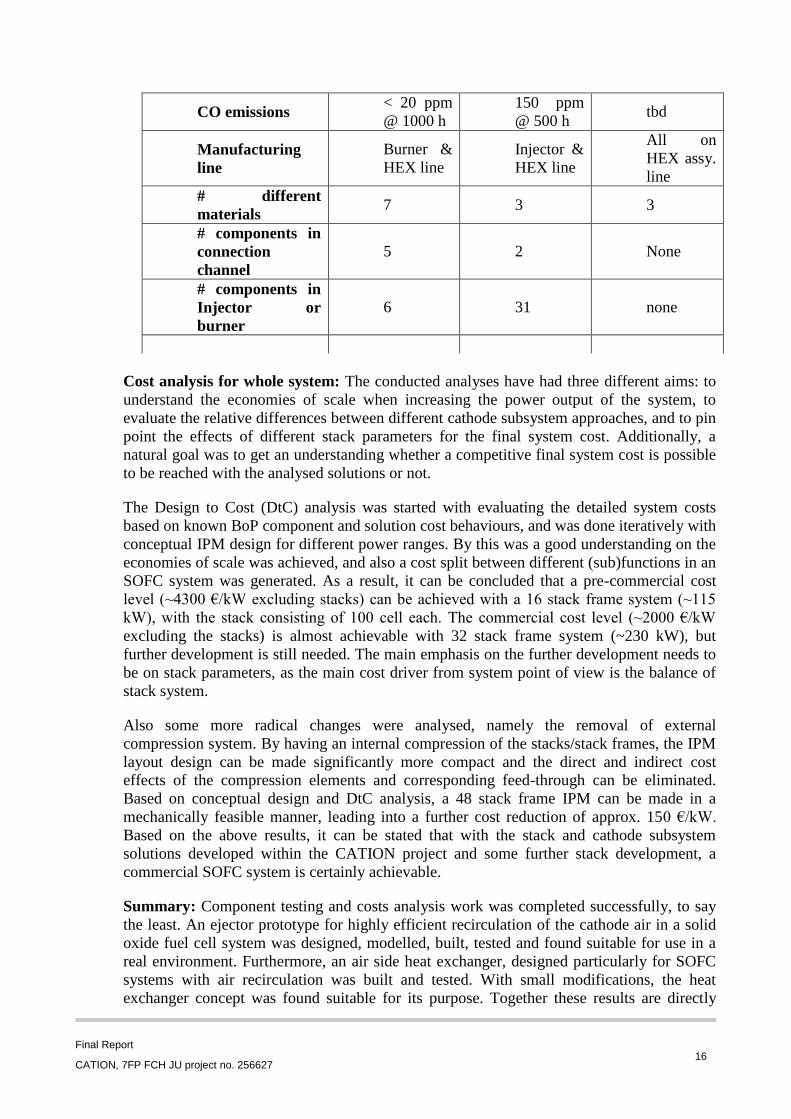
Integrated mixer: The integrated mixer offers considerable cost and volume benefits: It is
assembled on one of Bosal’s plate HEX assembly lines. The injection holes are drilled in the
HEX plates by the laser that welds the HEX core. Their dimensional tolerance is depicted in
Figure 13. The catalytic coating is also an existing feature, and requires no additional
development or tooling.
Figure 13 Dimensional tolerance and positions of the injection holes in a HEX plate. The
edge of the second picture shows the start of the HEX profiling. The coating (not visible)
starts at this edge.
The partly integrated cases (a and b) required an additional manufacturing line: in case a, the
design uses 7 different materials, including 4 ceramics: a ceramic monolith, a mounting mat
to fix the monolith, and a ceramic tube, limiting the thermal expansion of part of the
connection channel. Case b is more compact, but susceptible to uncontrolled partly
oxidation. Its CO emissions increase over time, reflecting poisoning or ageing of the
catalytic coating. The characteristics of these designs are listed in Table 3.
Table 3 Characteristics of three integration cases for the injection, oxidation and heat
exchange.
Case a:
catalytic
burner &
HEX
Case b:
injector /
mixer &
HEX
Case c:
integrated
mixer /
injector /
coated
HEX
Volume in hotbox
ex. outside tubing 4.0 l 1.5 l 1.3 l
Max. T wall 930 °C 930 °C 800 °C
Thermal duty 2500 W
Final Report
CATION, 7FP FCH JU project no. 256627 16
CO emissions < 20 ppm
@ 1000 h
150 ppm
@ 500 h tbd
Manufacturing
line
Burner &
HEX line
Injector &
HEX line
All on
HEX assy.
line
# different
materials 7 3 3
# components in
connection
channel
5 2 None
# components in
Injector or
burner
6 31 none
Cost analysis for whole system: The conducted analyses have had three different aims: to
understand the economies of scale when increasing the power output of the system, to
evaluate the relative differences between different cathode subsystem approaches, and to pin
point the effects of different stack parameters for the final system cost. Additionally, a
natural goal was to get an understanding whether a competitive final system cost is possible
to be reached with the analysed solutions or not.
The Design to Cost (DtC) analysis was started with evaluating the detailed system costs
based on known BoP component and solution cost behaviours, and was done iteratively with
conceptual IPM design for different power ranges. By this was a good understanding on the
economies of scale was achieved, and also a cost split between different (sub)functions in an
SOFC system was generated. As a result, it can be concluded that a pre-commercial cost
level (~4300 €/kW excluding stacks) can be achieved with a 16 stack frame system (~115
kW), with the stack consisting of 100 cell each. The commercial cost level (~2000 €/kW
excluding the stacks) is almost achievable with 32 stack frame system (~230 kW), but
further development is still needed. The main emphasis on the further development needs to
be on stack parameters, as the main cost driver from system point of view is the balance of
stack system.
Also some more radical changes were analysed, namely the removal of external
compression system. By having an internal compression of the stacks/stack frames, the IPM
layout design can be made significantly more compact and the direct and indirect cost
effects of the compression elements and corresponding feed-through can be eliminated.
Based on conceptual design and DtC analysis, a 48 stack frame IPM can be made in a
mechanically feasible manner, leading into a further cost reduction of approx. 150 €/kW.
Based on the above results, it can be stated that with the stack and cathode subsystem
solutions developed within the CATION project and some further stack development, a
commercial SOFC system is certainly achievable.
Summary: Component testing and costs analysis work was completed successfully, to say
the least. An ejector prototype for highly efficient recirculation of the cathode air in a solid
oxide fuel cell system was designed, modelled, built, tested and found suitable for use in a
real environment. Furthermore, an air side heat exchanger, designed particularly for SOFC
systems with air recirculation was built and tested. With small modifications, the heat
exchanger concept was found suitable for its purpose. Together these results are directly
Final Report
CATION, 7FP FCH JU project no. 256627 17
applicable to SOFC system development. Furthermore, the gathered test data and the
modelling information provide important and highly useful input to the design of SOFC
systems and further development of system components.
3.3 Balance of stack development
Stack module: Five full size OAM stack modules were tested to verify if they were feasible
within the CATION project. The test included fuel utilization, air utilization, and load
variations as well as load and thermal cycles. Both modules passed the test and it was
decided to continue with the present stack design. Additionally one of the modules was
tested for more than 1100 h, including more than 400 hours at nominal operation, 6 thermal
cycles, 5 load cycles (25-0 A on with NG as fuel and unchanged flows), three rounds of fuel
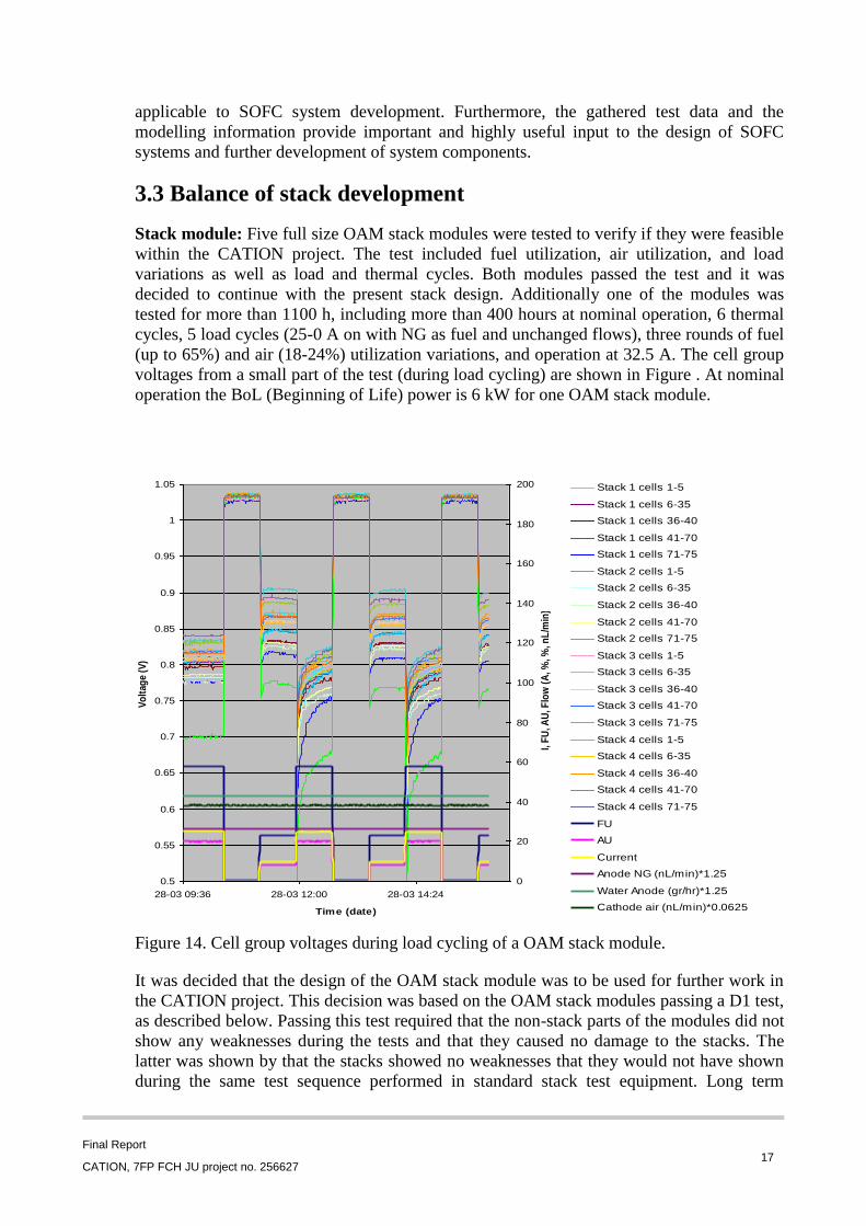
(up to 65%) and air (18-24%) utilization variations, and operation at 32.5 A. The cell group
voltages from a small part of the test (during load cycling) are shown in Figure . At nominal
operation the BoL (Beginning of Life) power is 6 kW for one OAM stack module.
Figure 14. Cell group voltages during load cycling of a OAM stack module.
It was decided that the design of the OAM stack module was to be used for further work in
the CATION project. This decision was based on the OAM stack modules passing a D1 test,
as described below. Passing this test required that the non-stack parts of the modules did not
show any weaknesses during the tests and that they caused no damage to the stacks. The
latter was shown by that the stacks showed no weaknesses that they would not have shown
during the same test sequence performed in standard stack test equipment. Long term
0.5
0.55
0.6
0.65
0.7
0.75
0.8
0.85
0.9
0.95
1
1.05
28-03 09:36 28-03 12:00 28-03 14:24
Time (date)
Vo
ltag
e (V
)
0
20
40
60
80
100
120
140
160
180
200
I, F
U, A
U, F
low
(A
, %, %
, nL
/min
)
Stack 1 cells 1-5
Stack 1 cells 6-35
Stack 1 cells 36-40
Stack 1 cells 41-70
Stack 1 cells 71-75
Stack 2 cells 1-5
Stack 2 cells 6-35
Stack 2 cells 36-40
Stack 2 cells 41-70
Stack 2 cells 71-75
Stack 3 cells 1-5
Stack 3 cells 6-35
Stack 3 cells 36-40
Stack 3 cells 41-70
Stack 3 cells 71-75
Stack 4 cells 1-5
Stack 4 cells 6-35
Stack 4 cells 36-40
Stack 4 cells 41-70
Stack 4 cells 71-75
FU
AU
Current
Anode NG (nL/min)*1.25
Water Anode (gr/hr)*1.25
Cathode air (nL/min)*0.0625
Final Report
CATION, 7FP FCH JU project no. 256627 18
performance was not included in the decision criteria.
The D1 test included:
Nominal operation (Pre-reformed NG as fuel, 60% fuel utilization, 21% air
utilization, 25 A current, 6 kW power, all temperatures was 650-750 oC).
Instant load cycles (only load varied).
Thermal cycles (to room temperature and back to operation).
Fuel utilization increase (65%).
Air utilization variations (18%, 21%, and 24%).
32.5 A load point at otherwise nominal operation.
Component test: Tests have been carried out to verify the performance of the module
components. The accuracy and sustainability has been verified for the compression system.
The feed through module was proven to be leak tight both before and after module test. The
bypass leakage was measured to be below 1% of the air supply on all tested modules; the
external leakage was in all cases below 0.1% and did not increase from before to after fuel
cell operation tests. Development and testing of the stacks was carried out in another TOFC
project.
One problem which at the beginning of the CATION project was very crucial to find a better
solution for was the electrical insulation between the stacks and the fuel manifold. The
previously used gasket was only resistive enough for having two stacks electrically in series.
A sub-project identified several possible options and tested their electrical resistance both
instantaneously and over time. The result was that a suitable material was identified as such
allows for the four stacks in one module to be operated in a serial configuration. This is of
importance for the system cost, as it decreases the required number of load supplies and a
higher output voltage is possible to obtain.
Hotbox: Main result of this work was the design and manufacturing/modification of
existing IPM to be able to accommodate 4 OAM stack frames and to use this test set up to
hot box validation tests. The hotbox validation test was successfully performed using the
hotbox design created in the CATION –project. Successful operation of the system for
2000+ hours validates the hotbox design as viable in a SOFC system environment.
Other achievements: AVL have in collaboration with Wärtsilä and TOFC completed risk
analysis, DFMEA, on the stack modules, on which they also performed damage modelling.
Additionally AVL prepared their 10 kW test station for a degradation test of one stack
module. FEM analysis has been applied to the stack module design and materials to ensure
that no unwanted deformations occur and CFD analysis has been applied to both the cathode
and anode flow to ensure proper flow distribution
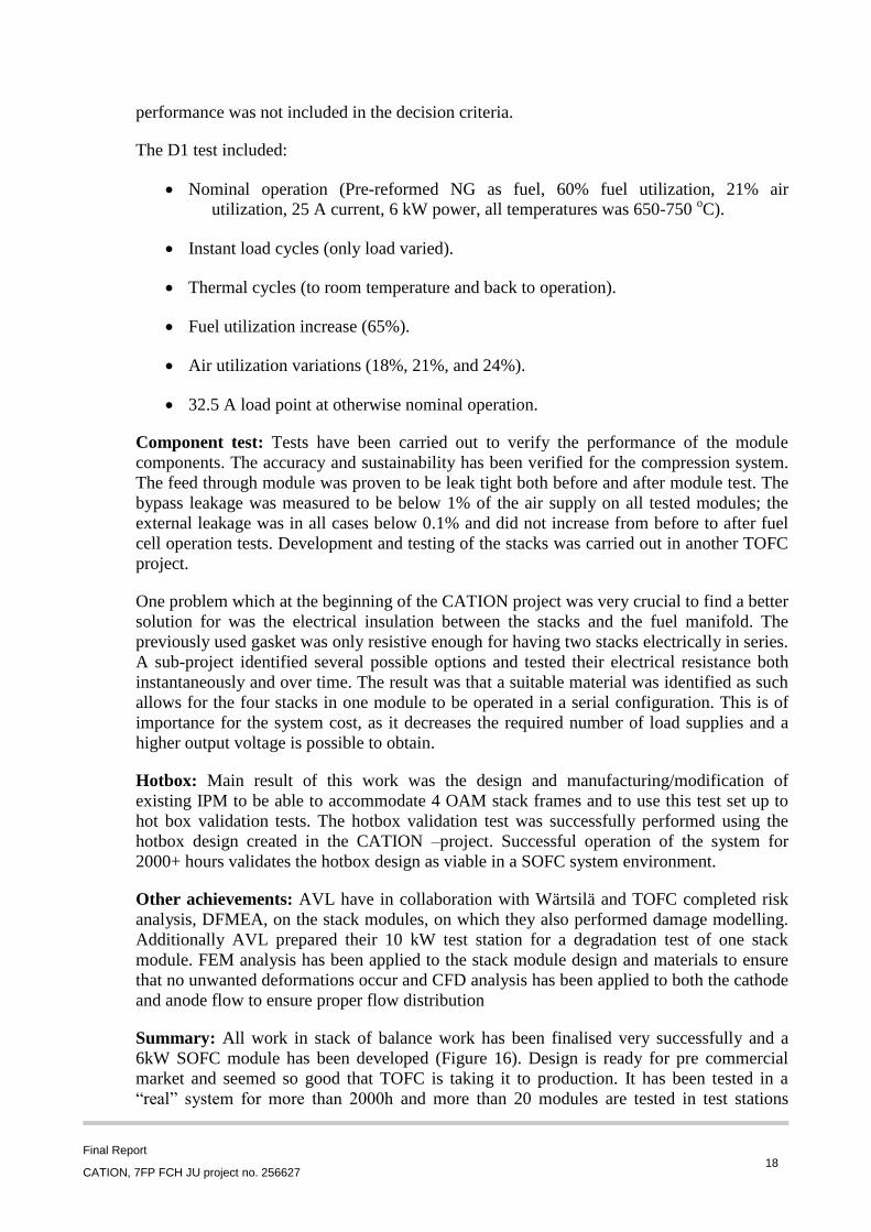
Summary: All work in stack of balance work has been finalised very successfully and a
6kW SOFC module has been developed (Figure 16). Design is ready for pre commercial
market and seemed so good that TOFC is taking it to production. It has been tested in a
“real” system for more than 2000h and more than 20 modules are tested in test stations
Final Report
CATION, 7FP FCH JU project no. 256627 19
making it a solid result.
Figure 16 The TOFC stack module.
3.4 Subsystem validation
Subsystem validation: The design study has shown that the required size of the ejector
allows for reasonable integration into the system. Furthermore, the required pressure at the
ejector inlet can be provided by the existing blowers of the system and does not require a re-
sourcing. Furthermore, the integration of the new TOFC stack module could be achieved
with little modifications. These facts widen the flexibility of AVLs SOFC CHP platform
significantly and can be seen as a major output of this project.
The system was operated at 6 – 8 kWel for a significant amount of time. The cathode
recirculation was indirectly measured by two different methods. Both methods suggest a
recirculation rate of about 40 %. The results of the project allowed for the following
insights:
Static ejector is suitable for cathode recirculation in terms of performance and the
possibility to integrate it in a reasonable way into a very compact system packaging
Pressure drop of the stack cathode side influences the recirculation rate significantly.
Pressure drop of TOFC stack module is small enough to enable a high recirculation
rate
Cathode recirculation generates less harsh temperature gradients at the cathode inlet
which was shown by very moderate temperature differences between cathode inlet
and the stack itself
Cathode recirculation rate varies only slightly in a wide operating range and
therefore allows a good characteristic for system operation
Pressure level needed for the ejector can be handled by the blowers of the AVL
SOFC CHP platform which enables an easy adaption of the BoP in case of cathode
recirculation
Air heat exchanger can be built ~30 % smaller compared to a system without
Final Report
CATION, 7FP FCH JU project no. 256627 20
cathode recirculation
Cathode recirculation allows for high electrical DC efficiencies up to 66 %.
Within this project AVL could significantly push the system development further towards a
commercial system technology. AVL has already developed successfully a stationary SOFC
CHP platform in the 10 kWel range based on natural gas steam reforming and anode gas
recirculation. In this project the next step by improving the cathode path enabled an
important knowledge gain on a theoretical and practical level. The ejector concept is seen to
play a significant role when it comes to substantial cost reduction. For AVL as an
engineering consultant this knowledge gain is of major importance and widens the
technology portfolio of AVL’s stationary SOFC CHP platform. In this way future customers
can be attracted and served much better. The hardware demonstration of the system is an
important tool to convince industrial customers when it comes to a series product
development stage.
Life Cycle Analysis: A comparative Life Cycle Assessment (LCA) and Life Cycle Cost
analysis (LCC) have been performed to evaluate the environmental and economic
performance of a Solid Oxide Fuel Cells designed with cathode sub-systems developed in
the project. An environmental performance comparison was built between a SOFC system
with ejector-based cathode recirculation and a gas microturbine. It was demonstrated that
the studied SOFC system is able to yield environmental benefits on the environmental load
from a life cycle point of view for all the impact categories considered with respect to the
conventional technology. At commercial level, it can be concluded that SOFC systems
present a lower total LCC with respect to microturbines both for industrial and household
applications, thus guaranteeing both environmental and economic sustainability.
Summary: Experimental system validation subsystem in real SOFC system was done
successfully to prove that air sub-system concept including all necessary components were
developed during the CATION project and could be implemented into future large-scale
commercial SOFC power plant.
3.5 Foreground
After the exit of Wärtsilä from the CATION project, AVL took over the cathode sub-system
validation task. The cathode sub-system was designed and tested based on the existing AVL
SOFC CHP platform. This required an adaption of the platform towards the process
requirements considering the operation of the TOFC stack module consisting of two TOFC
DG modules with each 6 kWe rated power. However, the cathode sub-system required the
integration of the cathode recirculation which is carried out with a specifically designed
ejector system. After building the SOFC platform and integrating the TOFC stack module a
sub-system validation test was performed. During the project developed air sub-system
concept including all necessary components were successfully validated.
Based on the design to cost (DtC) analyses carried out in the projects, a good understanding
on the economies of scale was achieved. It can be concluded that with additional stack
related development steps a commercially feasible system having an investment cost (excl.
stacks) of less than 2000 €/kW can be achieved. SOFC systems present a lower total
lifecycle cost than microturbines both for industrial and household applications, thus
Final Report
CATION, 7FP FCH JU project no. 256627 21
guaranteeing both environmental and economic sustainability of the SOFC technology.
The ultimate objective to have 250 kWe atmospheric SOFC system in future will be reached
within the time because Convion Oy (former Wärtsilä) will be launched 50 kWe 2014 and
their product portfolio contains systems up to 300 kWe. The knowledge and results obtained
from the CATION project have been extensively utilized in the development of Convion’s
systems, providing among others improved cost, performance and technical maturity of the
system. Also all deliverables was delivered and all milestones and objectives were reached
during the project. Conclusion is that CATION project was finalised successfully.
4. Potential impacts
4.1. General impacts
The CATION project directly contributed to the overall objectives of Call FCH-JU-2009-1,
Area SP1-JTI-FCH.3: Stationary Power generation & CHP, Topic SP1-JTIFCH. 2009.3.4:
Component improvement for stationary power applications by addressing the following fuel
cell functions and the corresponding components in particular:
Power generation unit (integrated stack/BoP)
Heat exchangers/Thermal management
Air and fluid flow equipment including subcomponents
Fluid supply and management including pumps, valves and flow meters
The outcome of the project is as planned benefiting all of the project participants, and also
the fuel cell community in general. While CATION project was a particularly fruitful effort
in technological development, further development will be essential for SOFC technology in
reaching commercial competitiveness and maturity. Successful publicly funded
demonstrations will play an important role in bridging “a valley of death” of
commercializing large fuel cell systems due to inherently higher single unit costs and
associated financial risks compared to small systems, making steps to series manufacturing
and reaching volume advantages.
4.2. The exploitation of results
4.2.1. TOFC
During the CATION project TOFC has developed a module with 4 open air manifold stacks.
The cathode flow to the stacks is simplified as one big square channel with all the stacks
placed directly in the air stream. This allows very easy and cheap cathode integration by a
simple combined flange. Result is possibility of cheaper systems with less and simpler
cathode piping and allows the modules to be operated in series (with need of air ejection).
The product has been brought to a pre commercial as first version state where pilot
production is possible and reliable in small volumes but still need verification testing and
design & optimization for cost, assembly, production, integration etc. TOFC is take this
product to pre commercial sale and will transfer it to pilot production. Depending on yield
and marked demand TOFC will produce at maximum two modules per week for pre
commercial sale and testing in-house and at integration partners. This pilot production itself
and the produced product and testing of this will be part a new development program and
Final Report
CATION, 7FP FCH JU project no. 256627 22
give valuable input on the complete added value chain. Having a small scale production is
deemed necessary to ever foresee and overcome the challenges from design and concept
input over sub suppliers handling, in house production, end of line testing, system design
and installation, operation and end of life handling, just to mention a few. TOFC intends to
start a development program that will take the current pre-commercial distributed generation
module to a product that can handle a commercial marked. This product should have the
potential to be a major player in the marked. Even thou many challenges is already known
and to some extend solution ideas are ready this will be a traveling in to the void and
impossible to predict, but TOFC estimates that it will take 5 years before the product is
ready. During this period there will properly be possibilities of upgrading the current
module. The project is planned as a four stage project as follow:
Concept generation: Based on experience from current product and production new
concepts are generated to ensure a wide solution space for the later selection.
Concept selection: Evaluation of the above mentioned concepts. Among this is the
current concept but the comparison evaluation will be stronger than 2just2 updating
the current
Product development: The selected concept is taking to working prototype level and
thoroughly tested
Product implementation: The prototype is taken to production. Experience tells that
this is not an easy task
The development in the CATION project has been closely aligned with the interest of TOFC
and it has certainly made a difference.
4.2.2. Bosal
Bosal has drafted a business plan for all heat exchangers for industrial applications, of which
SOFC plate heat exchangers are part of. A business unit (Bosal ECI) has been carved out of
the R&D department of Bosal’s Lummen (Belgium) plant. This business unit is based in
Vianen, The Netherlands, where a Bosal automotive supply plant is now being transformed
to a heat echanger plant. All hardware procured for tooling and production line will be
installed in this plant. SOFC heat exchangers developed during the CATION project are
expected to take up 40% of the order volume for this plant by the end of 2015. These
products are aimed for the European market for heating appliances, as mCHP systems enter
this market. East Asia and the US are mainly targeted for SOFC power plants, in the 25 –
1000 kWe power range. Commercial production for field testing has started in 2014. The
ramp up to serial production is projected in 2016, while 2015 already sees a substantial
increase in projected sales.
4.2.3. Convion (former Wärtsilä)
Within the project a number of conceptual mechanical layouts including SOFC stacks, feed
piping and key components were developed for the various flow configurations. Convion
has developed a stack module assembly based on TOFC stacks having improved power
density and lower manufacturing costs compared to earlier designs. This stack module can
be utilized in Convion’s stack-flexible SOFC system. Convion has designed commercial
Final Report
CATION, 7FP FCH JU project no. 256627 23
SOFC systems in the power class of 50-300kW since its founding in late 2012, inheriting
the IPR and key personnel from the Wärtsilä fuel cell development unit. Convion has
completed the design of its first 50kW product in spring 2014 and has recently started the
manufacturing of a pilot system to be commissioned in 2015. Commercialization and ramp-
up of production as well as introduction of a higher power range is foreseen for 2016-2018.
The knowledge and results obtained from the CATION project have been extensively
utilized in the development of Convion’s systems, providing among others improved cost,
performance and technical maturity of the system.
4.2.4. AVL
The SOFC technology will contribute significantly to an efficient power production of the
future society. Performancewise, SOFCs have already proven that they are capable to
exceed current power generation technologies by far especially in the smaller power range.
This advantage now needs to be transferred on a commercial level. For the future society
there will be an even stronger need for a clean, efficient and affordable power production to
meet the increasing demands in a sustainable way. The results of this project are an
important step towards the commercialisation of SOFC CHP systems. In particular the
cathode recirculation enables more robust and durable systems with a high potential for cost
reduction. Both, robustness and cost are key drivers towards the market entry and need to be
improved to provide competitive products. AVL is strongly focused to transfer these results
to a commercial level.
However, the primary exploitation scenario of AVL is to license the technology to OEMs.
AVL as an engineering consultant is not primarily interested in manufacturing and selling
products to enducers. AVL is therefore constantly in contact with potential industrial
customers to push the commercialisation of the SOFC technology. The operating results of
the SOFC CHP platform built in CATION will be used to further demonstrate the feasibility
of this technology and attract further customers to initiate series development projects. This
strategy has been proven to be successful already in the past. However, it has to be
mentioned that this technology cannot be transferred immediately to a commercial level.
Further R&D activities concerning for example operating strategies, durability, design to
manufacture or supply chain development will be still necessary
4.2.5. UNIGE
During CATION project UNIGE research team had the opportunity of sharpening the
application of the Life Cycle Assessment methodology to Solid Oxide Fuel Cell systems.
This field of application has been object of several projects in the last years within the
department but CATION project was the first where the dynamics of sub-systems were
studied in such deep detail. Besides, UNIGE research team had the chance to test the
specific methodological choices - refining ISO 14040 general rules for fuel cell systems –
derived from a specific guidance issued within FCH JU initiatives. The assessment studies
conducted within CATION project can be in fact considered as a validation test of the
methodological guidance for performing LCA on fuel cells. Moreover, UNIGE research
team developed a specific toolbox for integration of a cost indicator associated to the
assessment of the environmental load of a fuel cell system along its life cycle. A specific
toolbox has been developed by UNIGE for integrating LCA and LCC findings. It cannot be
considered as a commercial product, but it can be considered as a research tool that can be
Final Report
CATION, 7FP FCH JU project no. 256627 24
from now used by the research team in its future analysis.
4.2.6. VTT
VTT Technical Research Centre of Finland as a research institute will utilise increased
expertise and knowhow in the area of SOFC system development for contract research with
European enterprises and getting more FCH JU join project with European partners.
4.3. Dissemination activities
Even if the project was very much industrial oriented there were quite a lot scientific
activities including two scientific papers, one master thesis, eight oral presentations in
international conferences, one commercial flyer and two exhibitions in Hannover messe.