Embed Size (px)
Citation preview
INTRODUCTION
Fire detection and alarm system are design to provide warning of the outbreak of fire and allow appropriate fire fighting action to taken before the situation get out of control.
The design depends on.
A. Type of building –UBBL Requirement, Bomba Requirements.
B. Type of system to be install.
C. Type Of Fire Detection System.
DESIGN REQUIREMENTS
Codes & Standards
Automatic fire alarm system shall be
design based on B.S 5839 part 1 ~ part5:
1988, UBBL 1984 TENTH SCHEDULE.
Others standard LBS 1014 Loss
Prevention Certification Board
PLANING THE SYSTEM
Things to be considered.
What type system is proposed?
What action is the system expected to initiate in
the even of fire?
How big is the building and what type of
building?
Servicing arrangements.
Hidden cost to the user.
SELECTING THE TYPE OF
COVERAGE
Discussion with building owner, fire authority regarding to type of protection to be established for the particular building is crucial.
British Standard 5831 Part 1 1988 provide a on coding system which allow fire detection and alarm system design to be specified according to purpose and the extent of protection to be afforded.
SELECTING THE TYPE OF
COVERAGE
Classification of system
1. Manual Type (Type M)-System which provides manual alarm only.
2. Life Protection (Type L)-System which provides for the protection of life that is the safety of occupants.
SELECTING THE TYPE OF
COVERAGE
• Detection of fire.
• Initiate an alarm of fire.
• Provides sufficient time for occupants to
escape
Type L3-Covers escape routes and
adjoining room (detectors) should be
situated on to the escape routes.
SELECTING THE TYPE OF
COVERAGE
Type L2-Covers escape routes and
adjacent rooms and any other areas
where it is considered the occupants are
vulnerable.
Type L1- Total Coverage.
SELECTING THE TYPE OF
COVERAGE
Property Protection (Type P)
• Automatic detection of fire.
• Initiate an alarm of fire
• Indicate the location of fire within the premises
Type P2 covers all high risk area
Type P1 Total coverage.
HOW TO CONFIGURE ZONE
WITHIN PREMISES
What is fire zone?
The most positive and effective where of
limiting fire spread within the building is to
subdivide it into the smallest practicable
such a compartment is known as a zone.
Each zone will have separate numbers,
indications at the main fire alarm indicator.
ZONE CONFIGURATION
GUIDELINES Maximum Floor Area Of A Zone Should Not Exceed 2000M
The search distance , that is the distance that has to be traveled by a searcher within a fire zone in order to determine visually the position of fire (not reach the fire ) should not exceed 30m
A single zone may be extend to several fire compartments
If the total floor area of a building is 300m or less then the building need only be one zone regardless the number of floors.
If the total floor area of a building is greater then 300m then each floor shall be a separate zone (or set of zones, if the floor area is large enough) There are however two exception for this rules that is:
1. If Communication between two adjacent vertical compartments is at the lowest level, only then can each vertical compartment still be considered to be separate multi storied zones
2.Structures such as stairwell extending to more than one floor but remaining within the same vertical compartment still be considered separate multi stories zone.
For multi occupancy building, zone boundaries should not cross occupancy boundaries hence a zone should contain only one occupancy. This ruling may be relaxed for Type M system.
Zone Safeguards
Fault occurring at one zone should not effect the operation of
another zone.
- Line/zone isolating device for addressable system.
A single fault should not remove protection from an area greater
than that allowed for a single zone
Two fault should not remove protection from an area greater than
10,000 sq meter.
Short circuit should be reported by the control panel within 100
second of occurrence and open circuit should be reported within 60
minutes of occurrence
Type Of Alarm Detection
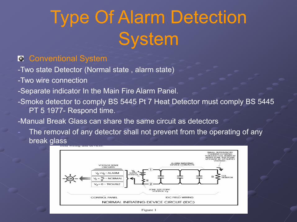
SystemConventional System
-Two state Detector (Normal state , alarm state)
-Two wire connection
-Separate indicator In the Main Fire Alarm Panel.
-Smoke detector to comply BS 5445 Pt 7 Heat Detector must comply BS 5445
PT 5 1977- Respond time.
-Manual Break Glass can share the same circuit as detectors
- The removal of any detector shall not prevent from the operating of any
break glass
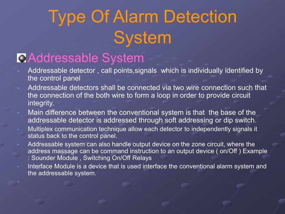
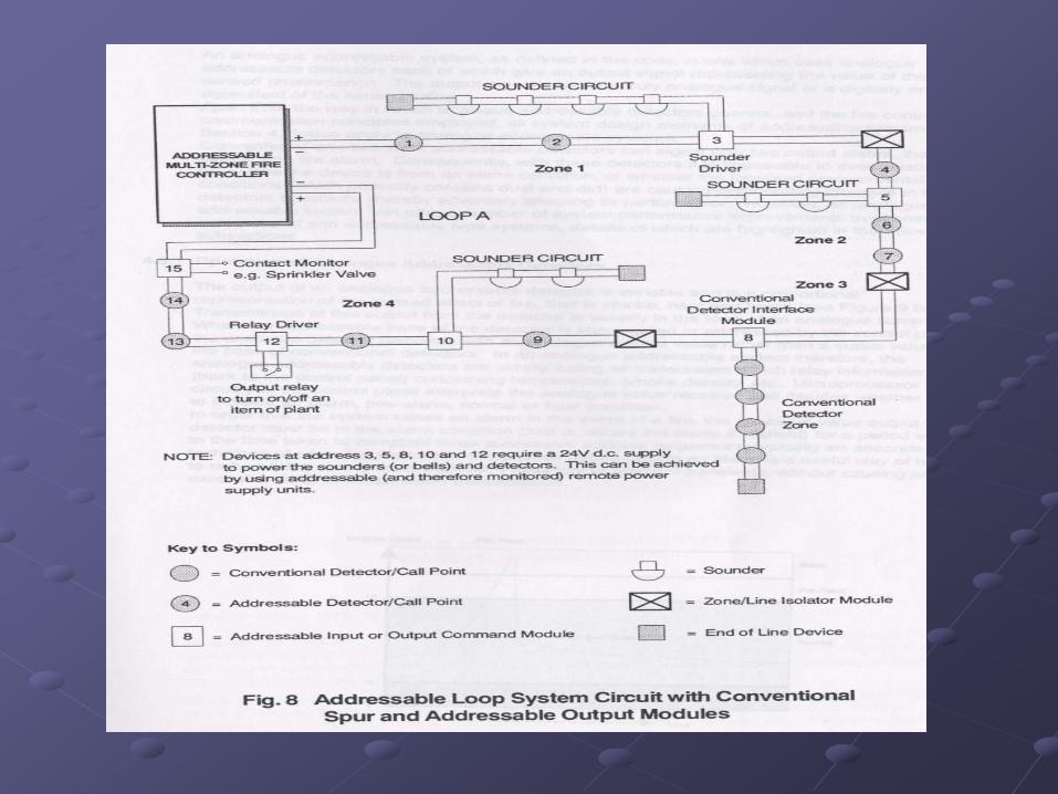
Type Of Alarm Detection
SystemAddressable System
- Addressable detector , call points,signals which is individually identified by the control panel
- Addressable detectors shall be connected via two wire connection such that the connection of the both wire to form a loop in order to provide circuit integrity.
- Main difference between the conventional system is that the base of the addressable detector is addressed through soft addressing or dip switch.
- Multiplex communication technique allow each detector to independently signals it status back to the control panel.
- Addressable system can also handle output device on the zone circuit, where the address massage can be command instruction to an output device ( on/Off ) Example : Sounder Module , Switching On/Off Relays
- Interface Module is a device that is used interface the conventional alarm system and the addressable system.
-
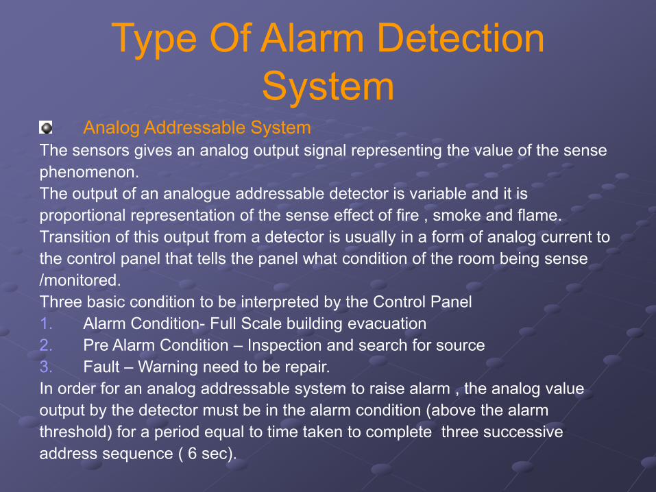
Type Of Alarm Detection
SystemAnalog Addressable System
The sensors gives an analog output signal representing the value of the sense
phenomenon.
The output of an analogue addressable detector is variable and it is
proportional representation of the sense effect of fire , smoke and flame.
Transition of this output from a detector is usually in a form of analog current to
the control panel that tells the panel what condition of the room being sense
/monitored.
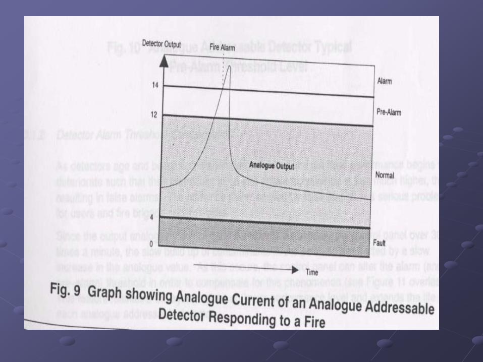
Three basic condition to be interpreted by the Control Panel
1. Alarm Condition- Full Scale building evacuation
2. Pre Alarm Condition – Inspection and search for source
3. Fault – Warning need to be repair.
In order for an analog addressable system to raise alarm , the analog value
output by the detector must be in the alarm condition (above the alarm
threshold) for a period equal to time taken to complete three successive
address sequence ( 6 sec).
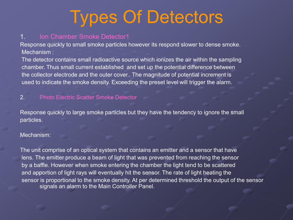
Types Of Detectors1. Ion Chamber Smoke Detector1
Response quickly to small smoke particles however its respond slower to dense smoke.
Mechanism :
The detector contains small radioactive source which ionizes the air within the sampling
chamber. Thus small current established and set up the potential difference between
the collector electrode and the outer cover.. The magnitude of potential increment is
used to indicate the smoke density. Exceeding the preset level will trigger the alarm.
2. Photo Electric Scatter Smoke Detector
Response quickly to large smoke particles but they have the tendency to ignore the small
particles.
Mechanism:
The unit comprise of an optical system that contains an emitter and a sensor that have
lens. The emitter produce a beam of light that was prevented from reaching the sensor
by a baffle. However when smoke entering the chamber the light tend to be scattered
and apportion of light rays will eventually hit the sensor. The rate of light heating the
sensor is proportional to the smoke density. At per determined threshold the output of the sensor signals an alarm to the Main Controller Panel.
Types Of Detectors
3. High Performance Smoke Detector
It responses to the some in the same way as the Photo Electric detector, but
there is a rapid rate of rise in temperature will be also taken into considerations
which in turn increase their sensitivity accordingly. Therefore this unit can also
pick up a very small smoke particles as per ionization Chamber type detector.
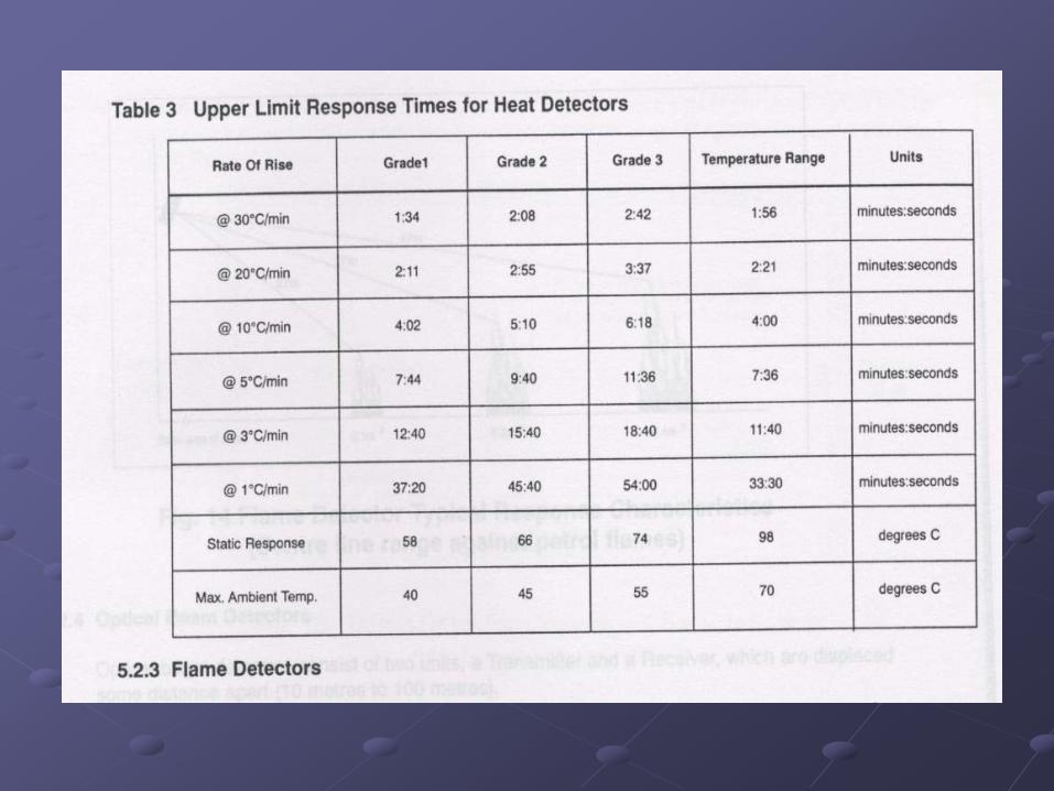
Types Of DetectorsHeat Detector.
Less sensitive alternative, to be use at the location where the smoke detector cannot be use.
To be use for monitoring product that will emit little smoke when burns.
Types of Heat Detector.
1. Rate Of Rise Detectors
React to abnormal high rise of change of temperature and provide fastest response over wide range
Of ambient temperature.
Suitable to be use where large change of ambient temperature will signals the alarm condition to
control panel.
2. Fixed Temperature Static Heat Detector.
Similar to rate of rise detector but it react to a fix predetermined temperature rather than rate of
Rise temperature. Suitable for the use in an area where sudden large change in temperature is
considered normal such as kitchen and boiler room.
3. Line type detectors
Not Commonly use , it comes in a log wire or tube and are design to sense the condition vicinity to the
line. Suitable for cable tunnel, subways duct, aircraft hangers.
Types Of Detectors
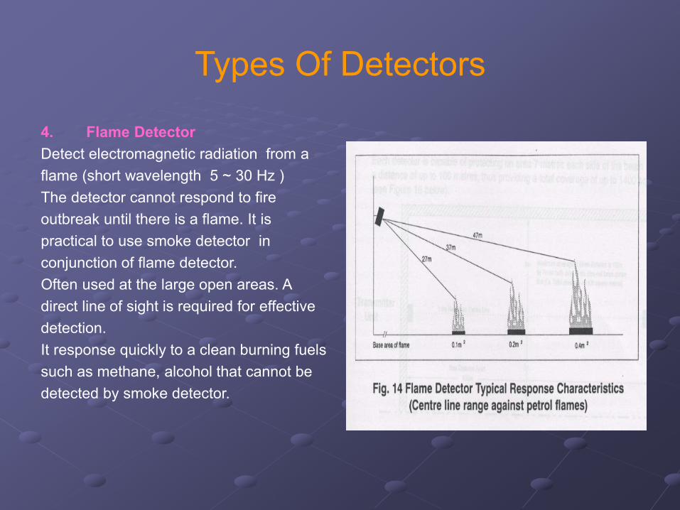
4. Flame Detector
Detect electromagnetic radiation from a
flame (short wavelength 5 ~ 30 Hz )
The detector cannot respond to fire
outbreak until there is a flame. It is
practical to use smoke detector in
conjunction of flame detector.
Often used at the large open areas. A
direct line of sight is required for effective
detection.
It response quickly to a clean burning fuels
such as methane, alcohol that cannot be
detected by smoke detector.
Types Of Detectors
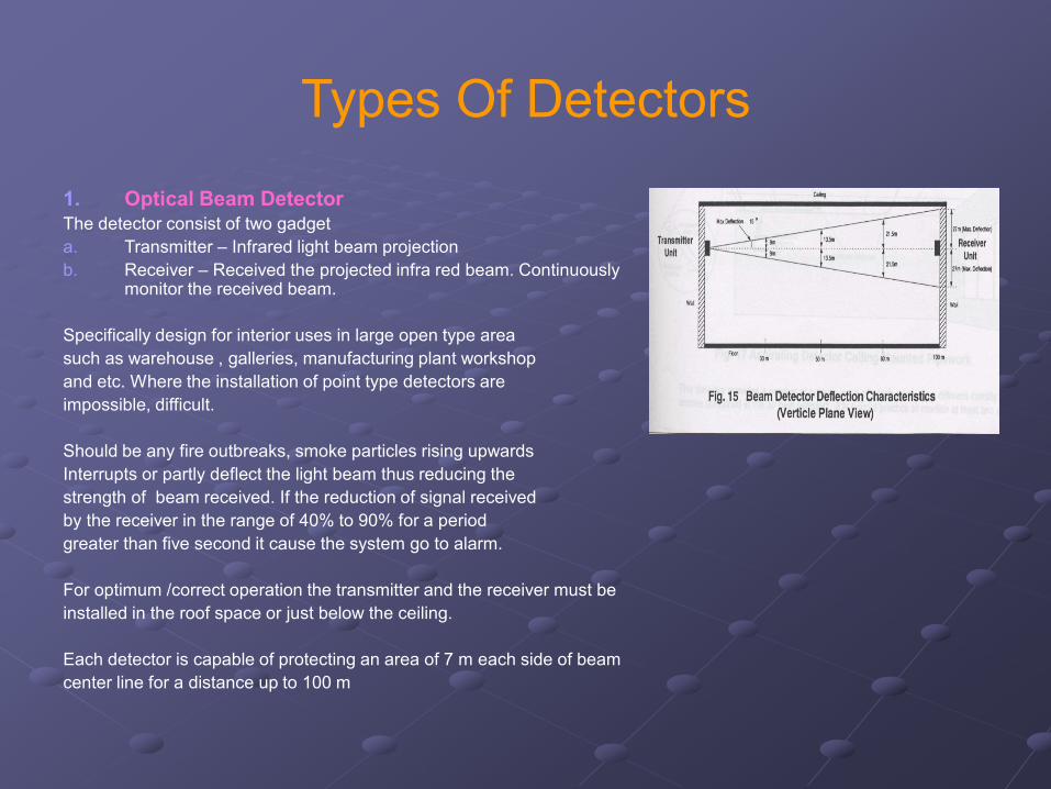
1. Optical Beam DetectorThe detector consist of two gadget
a. Transmitter – Infrared light beam projection
b. Receiver – Received the projected infra red beam. Continuously monitor the received beam.
Specifically design for interior uses in large open type area
such as warehouse , galleries, manufacturing plant workshop
and etc. Where the installation of point type detectors are
impossible, difficult.
Should be any fire outbreaks, smoke particles rising upwards
Interrupts or partly deflect the light beam thus reducing the
strength of beam received. If the reduction of signal received
by the receiver in the range of 40% to 90% for a period
greater than five second it cause the system go to alarm.
For optimum /correct operation the transmitter and the receiver must be
installed in the roof space or just below the ceiling.
Each detector is capable of protecting an area of 7 m each side of beam
center line for a distance up to 100 m
Types Of Detectors
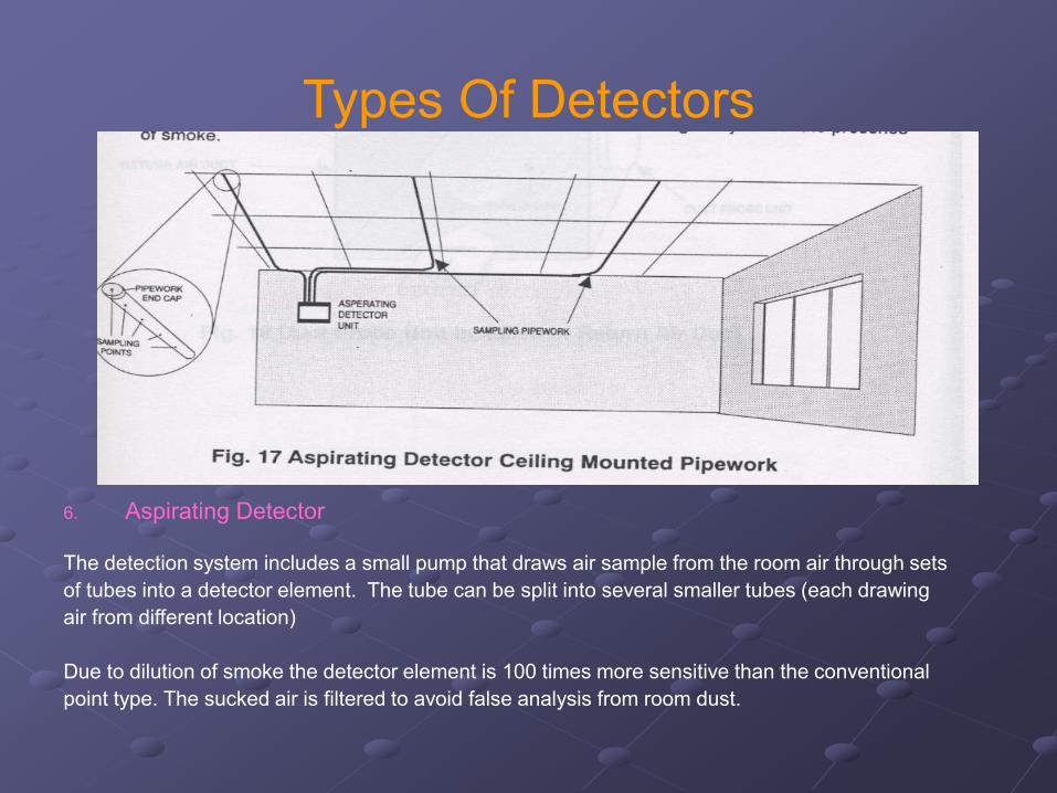
6. Aspirating Detector
The detection system includes a small pump that draws air sample from the room air through sets
of tubes into a detector element. The tube can be split into several smaller tubes (each drawing
air from different location)
Due to dilution of smoke the detector element is 100 times more sensitive than the conventional
point type. The sucked air is filtered to avoid false analysis from room dust.
Types Of Detectors
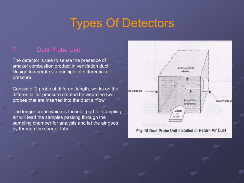
7. Duct Probe Unit.
The detector is use to sense the presence of
smoke/ combustion product in ventilation duct.
Design to operate via principle of differential air
pressure.
Consist of 2 probe of different length, works on the
differential air pressure created between the two
probes that are inserted into the duct airflow.
The longer probe which is the inlet port for sampling
air will lead the samples passing through the
sampling chamber for analysis and let the air goes
by through the shorter tube.
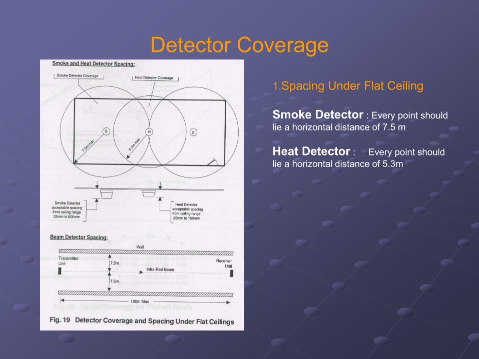
Detector Coverage
1.Spacing Under Flat Ceiling
Smoke Detector : Every point should
lie a horizontal distance of 7.5 m
Heat Detector : Every point should
lie a horizontal distance of 5.3m
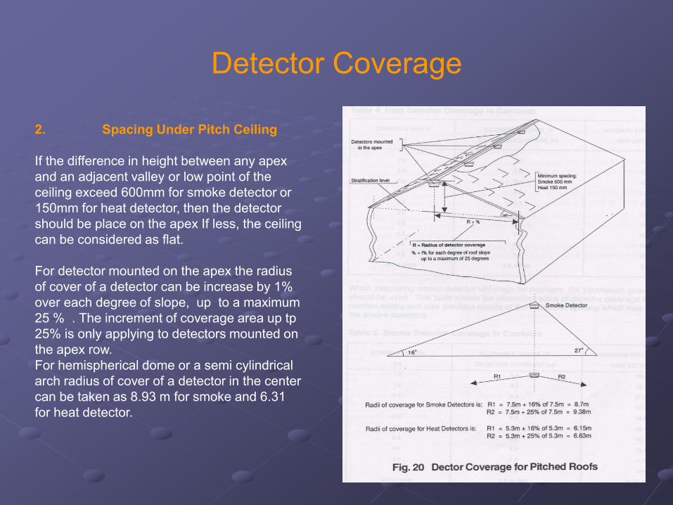
Detector Coverage
2. Spacing Under Pitch Ceiling
If the difference in height between any apex
and an adjacent valley or low point of the
ceiling exceed 600mm for smoke detector or
150mm for heat detector, then the detector
should be place on the apex If less, the ceiling
can be considered as flat.
For detector mounted on the apex the radius
of cover of a detector can be increase by 1%
over each degree of slope, up to a maximum
25 % . The increment of coverage area up tp
25% is only applying to detectors mounted on
the apex row.
For hemispherical dome or a semi cylindrical
arch radius of cover of a detector in the center
can be taken as 8.93 m for smoke and 6.31
for heat detector.
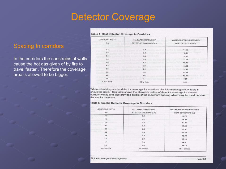
Detector Coverage
Spacing In corridors
In the corridors the constrains of walls
cause the hot gas given of by fire to
travel faster . Therefore the coverage
area is allowed to be bigger.
Detector Coverage
Obstruction
If the passage of smoke or hot gas is likely to be obstruct by ceiling obstruction such as
beam which has depth greater than 150 mm but less than 10 % of the height of the
ceiling then the normal coverage distance allowed for the smoke and heat detector
should be decrease by twice the depth of the obstruction
Smoke Detector Coverage Area : 7.5 m – ( 2 x obstruction depth)
Heat detector Coverage Area : 5.3 m – (2 x obstruction depth)
Wall and ceiling reaching within 300 mm off the ceiling or obstruction such as beam that
is deeper than 10% of the ceiling to floor height shall be treated as separate rooms.
Detector Coverage
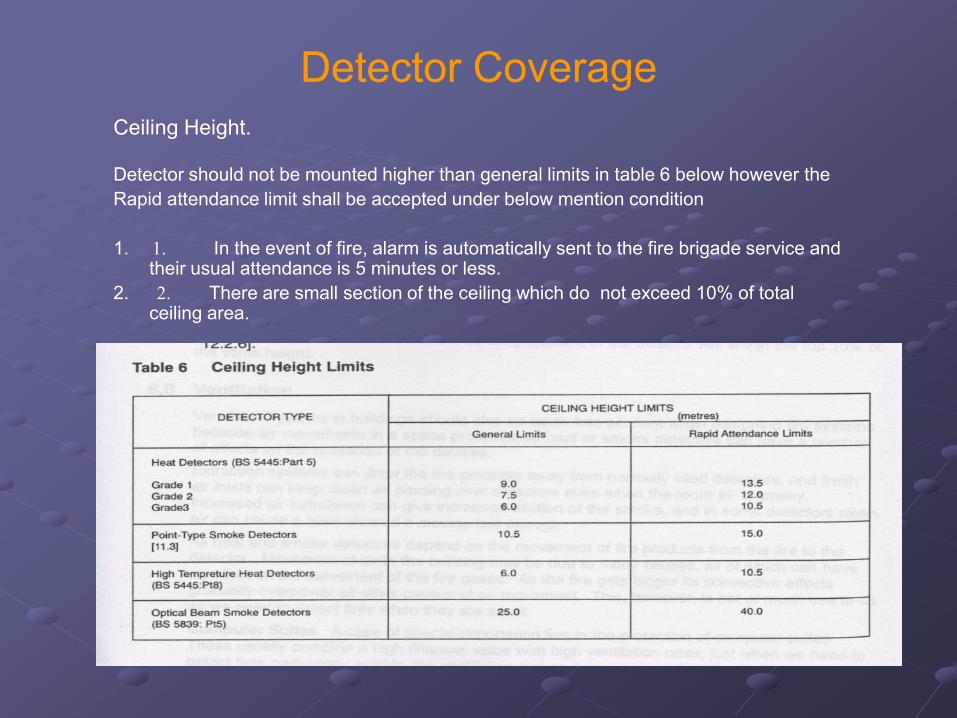
Ceiling Height.
Detector should not be mounted higher than general limits in table 6 below however the
Rapid attendance limit shall be accepted under below mention condition
1. 1. In the event of fire, alarm is automatically sent to the fire brigade service and their usual attendance is 5 minutes or less.
2. 2. There are small section of the ceiling which do not exceed 10% of total ceiling area.
Detector Coverage
Wall and Partition
Detector should not be mounted within 500 mm of any wall due to dead
spot near wall.
Void.
Ceiling and Under Voids 800 mm or more in height should also be zoned and
protected by detectors. Void less the 800 mm need not to be protected. Unless
extensive spread of fire or its product , particularly between rooms and
compartments can take place within it before detection.
Detector Coverage
Ventilation Effect
Movement of air can cause dilution of smoke /heat intensity until
detectors install cant detect the fire outbreak .
• Smoke test to be conducted to find the most effective
location of mounting detectors.
2. Use infrared beam type detectors if suitable.
3. Detectors should not be mount directly in the fresh air input
from air conditioning system. Generally spacing of detectors not
less than 1 m from the air intake should be maintained.
4. Use duct probe sensor.
Detector Coverage
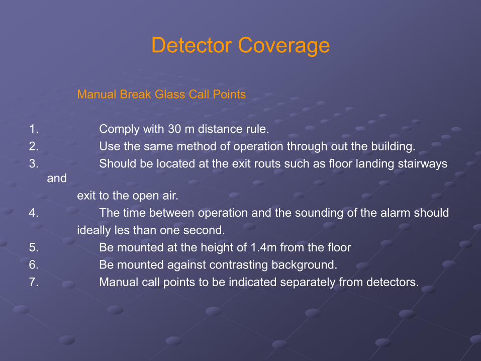
Manual Break Glass Call Points
1. Comply with 30 m distance rule.
2. Use the same method of operation through out the building.
3. Should be located at the exit routs such as floor landing stairways
and
exit to the open air.
4. The time between operation and the sounding of the alarm should
ideally les than one second.
5. Be mounted at the height of 1.4m from the floor
6. Be mounted against contrasting background.
7. Manual call points to be indicated separately from detectors.
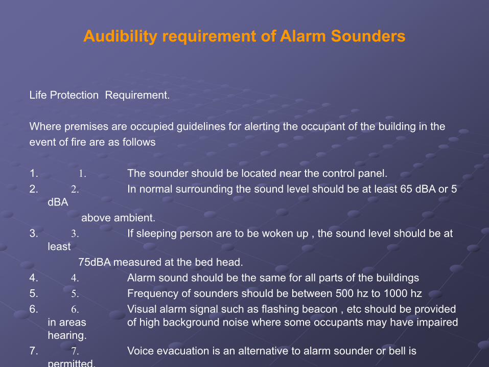
Audibility requirement of Alarm Sounders
Life Protection Requirement.
Where premises are occupied guidelines for alerting the occupant of the building in the
event of fire are as follows
1. 1. The sounder should be located near the control panel.
2. 2. In normal surrounding the sound level should be at least 65 dBA or 5
dBA
above ambient.
3. 3. If sleeping person are to be woken up , the sound level should be at
least
75dBA measured at the bed head.
4. 4. Alarm sound should be the same for all parts of the buildings
5. 5. Frequency of sounders should be between 500 hz to 1000 hz
6. 6. Visual alarm signal such as flashing beacon , etc should be provided
in areas of high background noise where some occupants may have impaired
hearing.
7. 7. Voice evacuation is an alternative to alarm sounder or bell is
permitted.
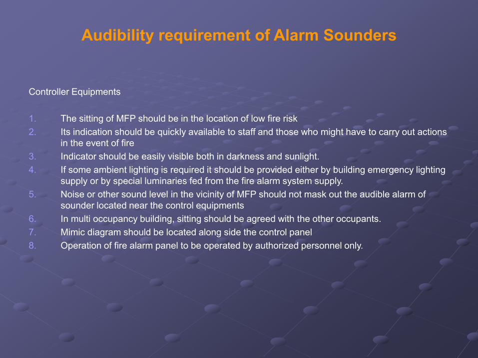
Audibility requirement of Alarm Sounders
Controller Equipments
1. The sitting of MFP should be in the location of low fire risk
2. Its indication should be quickly available to staff and those who might have to carry out actions
in the event of fire
3. Indicator should be easily visible both in darkness and sunlight.
4. If some ambient lighting is required it should be provided either by building emergency lighting
supply or by special luminaries fed from the fire alarm system supply.
5. Noise or other sound level in the vicinity of MFP should not mask out the audible alarm of
sounder located near the control equipments
6. In multi occupancy building, sitting should be agreed with the other occupants.
7. Mimic diagram should be located along side the control panel
8. Operation of fire alarm panel to be operated by authorized personnel only.

Power Supplies
Independent Power From Mains, Standby
Batteries with automatic charger
Battery life expectancy min of 4 years
Batteries capacity shall be able to support
running ampere of 24 hr supervisory load
and 30 min alarm mode.
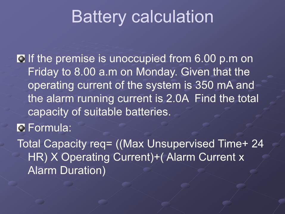
Battery calculation
If the premise is unoccupied from 6.00 p.m on
Friday to 8.00 a.m on Monday. Given that the
operating current of the system is 350 mA and
the alarm running current is 2.0A Find the total
capacity of suitable batteries.
Formula:
Total Capacity req= ((Max Unsupervised Time+ 24
HR) X Operating Current)+( Alarm Current x
Alarm Duration)