Embed Size (px)
Citation preview

Matthew E. MelisGlenn Research Center, Cleveland, Ohio
Finite Element Simulation of a Space ShuttleSolid Rocket Booster Aft Skirt SplashdownUsing an Arbitrary Lagrangian-EulerianApproach
NASA/TM—2003-212093
January 2003
https://ntrs.nasa.gov/search.jsp?R=20030016601 2019-12-27T01:36:16+00:00Z

The NASA STI Program Office . . . in Profile
Since its founding, NASA has been dedicated tothe advancement of aeronautics and spacescience. The NASA Scientific and TechnicalInformation (STI) Program Office plays a key partin helping NASA maintain this important role.
The NASA STI Program Office is operated byLangley Research Center, the Lead Center forNASA’s scientific and technical information. TheNASA STI Program Office provides access to theNASA STI Database, the largest collection ofaeronautical and space science STI in the world.The Program Office is also NASA’s institutionalmechanism for disseminating the results of itsresearch and development activities. These resultsare published by NASA in the NASA STI ReportSeries, which includes the following report types:
• TECHNICAL PUBLICATION. Reports ofcompleted research or a major significantphase of research that present the results ofNASA programs and include extensive dataor theoretical analysis. Includes compilationsof significant scientific and technical data andinformation deemed to be of continuingreference value. NASA’s counterpart of peer-reviewed formal professional papers buthas less stringent limitations on manuscriptlength and extent of graphic presentations.
• TECHNICAL MEMORANDUM. Scientificand technical findings that are preliminary orof specialized interest, e.g., quick releasereports, working papers, and bibliographiesthat contain minimal annotation. Does notcontain extensive analysis.
• CONTRACTOR REPORT. Scientific andtechnical findings by NASA-sponsoredcontractors and grantees.
• CONFERENCE PUBLICATION. Collectedpapers from scientific and technicalconferences, symposia, seminars, or othermeetings sponsored or cosponsored byNASA.
• SPECIAL PUBLICATION. Scientific,technical, or historical information fromNASA programs, projects, and missions,often concerned with subjects havingsubstantial public interest.
• TECHNICAL TRANSLATION. English-language translations of foreign scientificand technical material pertinent to NASA’smission.
Specialized services that complement the STIProgram Office’s diverse offerings includecreating custom thesauri, building customizeddatabases, organizing and publishing researchresults . . . even providing videos.
For more information about the NASA STIProgram Office, see the following:
• Access the NASA STI Program Home Pageat http://www.sti.nasa.gov
• E-mail your question via the Internet [email protected]
• Fax your question to the NASA AccessHelp Desk at 301–621–0134
• Telephone the NASA Access Help Desk at301–621–0390
• Write to: NASA Access Help Desk NASA Center for AeroSpace Information 7121 Standard Drive Hanover, MD 21076

Matthew E. MelisGlenn Research Center, Cleveland, Ohio
Finite Element Simulation of a Space ShuttleSolid Rocket Booster Aft Skirt SplashdownUsing an Arbitrary Lagrangian-EulerianApproach
NASA/TM—2003-212093
January 2003
National Aeronautics andSpace Administration
Glenn Research Center

Acknowledgments
The author would like to thank Mike Pereira and Kelley Carney, NASA Glenn Research Center, Dallas McFadden,Richard Knockelman, and Pete McFadden, United States Alliance, and Khanh Bui, Livermore Software TechnologyCorporation, for their contributions to this work, which greatly enhanced my efforts to characterize this problem.
Available from
NASA Center for Aerospace Information7121 Standard DriveHanover, MD 21076
National Technical Information Service5285 Port Royal RoadSpringfield, VA 22100
Trade names or manufacturers’ names are used in this report foridentification only. This usage does not constitute an officialendorsement, either expressed or implied, by the National
Aeronautics and Space Administration.
Available electronically at http://gltrs.grc.nasa.gov

NASA/TM—2003-212093 1
Figure 2. Spashdown Orientation of SRB.Figure 1. Primary Components ofSpace Shuttle Launch Configuration.
Aft Skirt
SpaceShuttleOrbitalVehicle
ExternalTankSolid
RocketBoosters
Aft Skirt
Ocean Surface
Finite Element Simulation of a Space Shuttle Solid Rocket Booster Aft Skirt SplashdownUsing an Arbitrary Lagrangian-Eulerian Approach
Matthew E. MelisNational Aeronautics and Space Administration
Glenn Research CenterCleveland, Ohio 44135
ABSTRACT
Explicit finite element techniques employing an Arbitrary Lagrangian-Eulerian (ALE) methodology, within the transient dy-namic code LS-DYNA, are used to predict splashdown loads on a proposed replacement/upgrade of the hydrazine tanks on thethrust vector control system housed within the aft skirt of a Space Shuttle Solid Rocket Booster. Two preliminary studies areperformed prior to the full aft skirt analysis: An analysis of the proposed tank impacting water without supporting aft skirtstructure, and an analysis of space capsule water drop tests conducted at NASA’s Langley Research Center. Results from thepreliminary studies provide confidence that useful predictions can be made by applying the ALE methodology to a detailedanalysis of a 26-degree section of the skirt with proposed tank attached. Results for all three studies are presented and comparedto limited experimental data. The challenges of using the LS-DYNA ALE capability for this type of analysis are discussed.
INTRODUCTION
Reusing the Solid Rocket Boosters (SRB’s) on NASA’s Space Shuttle saves millions of dollars each launch. At the end of theirduty cycle, the boosters separate from the shuttle’s external tank, descend to earth via parachutes, and splashdown in the oceanfor recovery. Typical splashdown velocities of 80 feet per second create significant impact loads to the SRB structure, particu-larly to the aft skirt and its components. Figure 1 shows the SRBs integrated with the external tank and space shuttle orbitervehicle in launch configuration. Figure 2 identifies the aft skirt on the SRB and depicts the orientation of the booster as itsplashes down into the ocean.

NASA/TM—2003-212093 2
Figure 3. Aft Skirt in NASA Assembly Facility Awaiting Integration to SRB.
Figure 4. Thrust Vector Control System Inside Space Shuttle SRB.
Figure 3 shows a photograph of an actual aft skirt awaiting integration to an SRB (personnel in this figure provide a reference forscale). Each SRB aft skirt houses a complex thrust vector control system (TVC), which mechanically directs the nozzle at theend of the booster to steer the shuttle during its initial ascent. The TVC consists of two hydraulic gimbal servo-actuators; eachindependently powered by its own auxiliary power unit (APU) and hydraulic system. Figure 4 is a photograph of the TVCsystem inside the aft skirt with the actuators, APUs and hydrazine tanks identified. Hydrazine, currently used as the propellantfor the TVC, is an extremely hazardous material. Safety concerns, regarding this hazard, have provided motivation to propose anew propellant system using helium in place of hydrazine.
NASA/TM—2003-212093 3
Experience with over 100 launches has enabled NASA to understand and minimize splashdown damage to current aft skirt andTVC components. The proposed helium tanks, however, are approximately six times the volume of the hydrazine tanks andwould significantly change the exposure characteristics of water impact loads to the system should they be implemented. As aconsequence, a new detailed analysis of the water impact event with the new helium tanks would be required during the designstage.
Only recently has the ALE capability in LS-DYNA1, an explicit finite element code (ref. 1), become feasible for analyzing waterimpact problems. The primary objective of this work is to establish the practicality of using such methods to model the SRBsplashdown event in a timely fashion. To demonstrate this, LS-DYNA is used to analyze several different types of water impactproblems. The analysis results, presented here, are in general agreement with the limited qualitative and quantitative experimen-tal data available for comparison. This provides encouragement that the LS-DYNA ALE capability will be useful for character-izing complex water impact problems such as this one.
Modeling Approach and Analysis Results
The Arbitrary-Lagrangian-Eulerian method utilizes two mesh types in an analysis: The Lagrangian mesh, associated with thetypical finite element analysis, distorts as it responds to the loading and boundary conditions in the analysis. The Eulerian mesh,conversely, remains fixed throughout the analysis and tracks material as it moves throughout the mesh. Combining these twomeshes together in a single analysis provides the ability to predict the interaction between fluid and structural elements. The ALEapproach was suited perfectly for this analysis with the SRB structure being modeled with the Lagrangian mesh, and the waterbeing modeled with the Eulerian mesh.
This effort was broken into three analysis tasks. The first two were performed to establish a workflow methodology for conduct-ing the ALE analyses with LS-DYNA, as well as to develop a level of confidence that the LS-DYNA results were reasonable. Allof the analysis results presented here were run on a single processor Silicon Graphics Origin 2000 R10000 processor. Theresults from the first two analysis tasks yielded reasonable predictions, as will be discussed, and provided justification to committhe recourses to perform a full-scale aft skirt analysis.
One of the most significant issues in this effort was the determination of material properties and the respective constitutivemodels to be used to characterize water for the analyses. LS-DYNA enables the user to choose from a variety of material modelsfor property definitions, however, in the absence of an advanced material model for water, the most rudimentary characterizationof water was made for these analyses using the LS-DYNA MAT_ELASTIC_FLUID definition. Three parameters were explic-itly defined on this card: Water density, bulk modulus, and a tensor viscosity coefficient. Density and elastic modulus values,taken from the literature, were 9.59e-5 lbm/in3, 3.30e5 lb/in2, respectively. A tensor viscosity value of .05 was assigned based onrecommendations from the Livermore Software Technology Corporation, and a default value for cavitation pressure of 1.0E20lb/in2 was used.
In each case, symmetric boundary conditions were utilized to reduce the problem size. These constraints were applied to theALE mesh in the same fashion as one would for a typical ALE structural analysis. In other words, nodes that lie on a plane ofsymmetry were constrained to move only within that plane. Eight-node bricks were used for all of the Eulerian fluid mesheswhich consisted of water and void. A void region must be defined to represent the air above the fluid free surface in order toaccommodate the splash effect upon impact. For ease of visualization, elements representing voids in the models are not shownin the figures to follow. The Eulerian mesh sizes were somewhat driven by the Lagrangian meshes in these problems. Once thestructural mesh was developed, the fluid mesh was created with the same general element sizes in order to avoid contact prob-lems that can occur with elements that have noticeable disparity in their sizes.
Initial velocities of the impacting structure for each analysis presented in this paper were set in the direction vertically towardsthe horizontal free surface of the fluid mesh. No lateral initial velocities were assigned for any analysis.

NASA/TM—2003-212093 4
Figure 5. Mesh for Helium Tank Water ImpactAnalysis.
Helium Tank Water Impact AnalysisThe first analysis modeled a half section of the proposed helium tankimpacting a volume of water as an independent structure. The primarypurpose of this analysis was to establish that the ALE methodology wasworking properly and to develop an idea as to what fidelity of mesh wouldbe necessary to get reasonable results. The mesh, shown in Figure 5,consisted of 77184 elements and 82228 nodes. Symmetry was used tomodel half of the problem. The tank, made of four-node shell elements,was defined as elastic steel 0.5” thick. Elastic modulus, density, andPoisson’s ratio were 28.0e6 lb/ in2, 7.24e-4 lbm/in3, and 0.3 respectively.An initial velocity of 960 inches/sec was assigned to the tank.
ResultsRunning the analysis to .1653 seconds took just over 38 cpu hours. Thepredicted cavity formed in the water by the impacting tank was comparedto high-speed photographic images of a ball bearing being dropped into avessel filled with water. No scientific effort was made to establish scalingor similarity parameters between the predicted and measured events but itwas noteworthy to see the striking resemblance of the two cavity forma-tions. It was considered to be a positive outcome that the most basicnumerical representation of water used with a DYNA ALE analysis ap-peared to be capturing the general behavior of a water/structure impact.Figure 6 shows a side-by-side comparison of the DYNA prediction with ahigh-speed image.
Figure 6. Comparison of DYNA Analysis of Helium Tank Water Impact with High Speed FilmImage of Ball Bearing Impact in Water Bucket.
Reentry Capsule Water ImpactThis second analysis was chosen for both the simplicity of the problem and the existence of experimental observations. It wasbased on an experimental program conducted at NASA’s Langley Research Center in 1959,2 to define the water landing charac-teristics of a space capsule similar to that used for the Mercury Program. The primary focus of the research was to establish peakdecelerations for various splashdown orientations of the capsule for both full and 1/12-scale test articles.
NASA/TM—2003-212093 5
Figure 7. Mesh for Reentry CapsuleWater Impact Analysis.
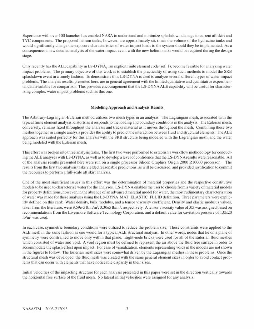
These experiments were conducted using several different initial conditions; however,only one case was selected for DYNA analysis: A full-scale capsule impacting a body ofwater at 360 inches per second. The full-scale capsule was 10.5 feet in height, 7.0 feetin diameter at the base, and weighed 2150 lb. Figure 7 depicts the capsule and fluidmesh created for this analysis. As with the previous problem, symmetry was used toreduce the problem size by half. This model consisted of 84836 elements and 90066nodes. Primary interest was in predicting the capsule deceleration; hence, the capsulewas modeled from four-node shells as a magnesium rigid body with an accelerometerelement added to it. Elastic modulus and density for the capsule were 6.5e6 lb/ in2,1.674e-4 lbm/in3 respectively.
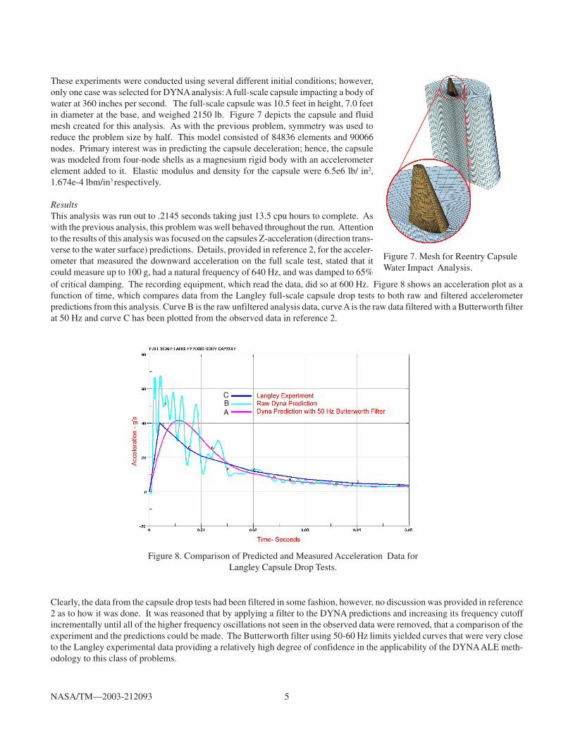
ResultsThis analysis was run out to .2145 seconds taking just 13.5 cpu hours to complete. Aswith the previous analysis, this problem was well behaved throughout the run. Attentionto the results of this analysis was focused on the capsules Z-acceleration (direction trans-verse to the water surface) predictions. Details, provided in reference 2, for the acceler-ometer that measured the downward acceleration on the full scale test, stated that itcould measure up to 100 g, had a natural frequency of 640 Hz, and was damped to 65%of critical damping. The recording equipment, which read the data, did so at 600 Hz. Figure 8 shows an acceleration plot as afunction of time, which compares data from the Langley full-scale capsule drop tests to both raw and filtered accelerometerpredictions from this analysis. Curve B is the raw unfiltered analysis data, curve A is the raw data filtered with a Butterworth filterat 50 Hz and curve C has been plotted from the observed data in reference 2.
Figure 8. Comparison of Predicted and Measured Acceleration Data forLangley Capsule Drop Tests.
Clearly, the data from the capsule drop tests had been filtered in some fashion, however, no discussion was provided in reference2 as to how it was done. It was reasoned that by applying a filter to the DYNA predictions and increasing its frequency cutoffincrementally until all of the higher frequency oscillations not seen in the observed data were removed, that a comparison of theexperiment and the predictions could be made. The Butterworth filter using 50-60 Hz limits yielded curves that were very closeto the Langley experimental data providing a relatively high degree of confidence in the applicability of the DYNA ALE meth-odology to this class of problems.
BC
A

NASA/TM—2003-212093 6
Full Scale Aft Skirt AnalysisResults of the helium tank and reentry capsule analyses provided confidence that it would be worthwhile to pursue a full scale aftskirt analysis. A mesh was constructed of a 26-degree section of an SRB aft skirt with the proposed helium tank integrated intothe structure. The mesh for the aft skirt analysis, seen in Figures 9a and 9b, contained 164537 nodes and 161133 elements. Themajority of the structural model was made up of shell elements, which lay on the geometric centerlines of the plate structure theywere representing. In some areas, plates were welded or bolted together on the skirt to add more strength to the overall structure.These instances were modeled by connecting the joined panels with very stiff beam elements whose lengths were determined bythe distance between the centerlines of those panels. Over 8000 beams were used in this model. Contact between fluid andstructure was limited to the aft skirt outer skin, the three main circumferential stiffening rings, and the helium tank. The initialvelocity of the skirt was 960 inches per second. The aft skirt was modeled entirely as an elastic material using aluminum for thematerial properties. Density, elastic modulus, and Poisson’s ratio, were 2.656e-4 lbm/in3, 10.5e6 lb/in2, and .33 respectively.
Figure 9. Mesh for Full Scale SRB Aft Skirt Water Impact Analysis.
(a) (b)
Results
Running this analysis to .09 seconds took 510 cpu hours to complete. The analysis was well behaved up to .03 seconds at whichpoint a notable increase in hourglass energy was observed indicating that remeshing portions of the mesh might be necessary.Figure 10 shows five instances from the analysis. Note that the model predicts the secondary water impacts on the middle andupper channel sections of the skirt. Post impact inspection of the aft skirt has indicated the existence of these secondary waterimpacts. Figure 11 is a graph comparing measured and predicted accelerometer data. The measured data was taken from anonboard data acquisition system (DAS) on the left hand booster from the STS-106 mission.3 This data was provided electroni-cally from SRB engineers at Kennedy Space Center. No filtering was applied to the DYNA predictions and it is unknown what,if any, filtering was applied to the measured data. With the exception of the initial spike in the DYNA data, it can be argued thatthere is general agreement between analysis and prediction. The sampling rate of the DAS data was substantially less than thatof the analysis and in order to make a stronger case for agreement between results, a higher DAS sampling rate would be desired.
Expertise with data filtering techniques of accelerometer data is a necessity in order to make quality assessments as to the validityof analysis predictions for problems of this nature, particularly when comparing measured and computed data. Future work onthis problem will employ a filtering technique in order to make better engineering judgments from the data.

NASA/TM—2003-212093 7
SUMMARY
Using LS-DYNA with its ALE capability to characterize a Space Shuttle Solid Rocket Booster splashdown event with reasonableresults has been demonstrated suggesting that this analysis technique could yield valuable insight to water impact problems.Future work is anticipated on analyzing the latter part of the SRB splashdown event in which the booster falls on its side and theforward skirt at the top of the booster is potentially subjected to severe water impact loads.
Several issues were brought to light during this project; 1) the water model used in this analysis was a very rudimentary one as noverified material models were available for our use in this problem. It would be of significant value should a more robustcharacterization of water be developed for this class of problems. 2) The computational demands of a problem of this nature areimmense as demonstrated by the full aft skirt analysis. In order to keep the analysis turnaround times to a reasonable level, themodels in this effort were held to under 200,000 elements, however it ultimately would be desired that we increase the resolution
Time = 0.02 seconds Time = 0.035 seconds Time = 0.045 seconds
Time = 0.055 seconds Time = 0.07 seconds
Figure 10. Five Animation Images at Various Time Steps from Full Aft Skirt Analysis.
Figure 11. Comparison of Predicted and Measured Acceleration Datafor Full Aft Skirt Splashdown.

NASA/TM—2003-212093 8
of our ALE mesh by a factor of 8 to 10 in order to obtain a better solution. Further investigation is in order to develop a parallelsolution procedure enabling a model of higher resolution. 3) Early considerations in setting up the meshes for these analysesincluded the use of non-reflecting boundary conditions on the ALE mesh. Some problems were created in using these and it wasdecided to apply basic planar constraints to the planes of symmetry to simplify the problem. It is possible that a better-condi-tioned analysis might be obtained using the non-reflecting constraints and this issue should be considered in future analyses ofthis type. 4) Data filtering (numerically removing non-pertinent frequency data from the experimental and computational results)is imperative for correct interpretation of such highly transient results. Without a strong fundamental understanding of filteringtechniques, the quality of engineering decisions made from impact analyses is reduced.
REFERENCES
1. LS-DYNA Keyword Users Manual, Livermore Software Technology Corporation, Livermore, CA, March 2001,Version 960.
2. McGehee, J.R. and Hathaway, M.E. (1959). “ Water-Landing Characteristics of a Reentry Capsule” NASAMemo 5-32-59L NASA Langley Research Center, Langley Field, VA.
3. REFERENCE TO REPRESENT DATA E-MAILED FROM ENGINEERS AT KSC.


This publication is available from the NASA Center for AeroSpace Information, 301–621–0390.
REPORT DOCUMENTATION PAGE
2. REPORT DATE
19. SECURITY CLASSIFICATION OF ABSTRACT
18. SECURITY CLASSIFICATION OF THIS PAGE
Public reporting burden for this collection of information is estimated to average 1 hour per response, including the time for reviewing instructions, searching existing data sources,gathering and maintaining the data needed, and completing and reviewing the collection of information. Send comments regarding this burden estimate or any other aspect of thiscollection of information, including suggestions for reducing this burden, to Washington Headquarters Services, Directorate for Information Operations and Reports, 1215 JeffersonDavis Highway, Suite 1204, Arlington, VA 22202-4302, and to the Office of Management and Budget, Paperwork Reduction Project (0704-0188), Washington, DC 20503.
NSN 7540-01-280-5500 Standard Form 298 (Rev. 2-89)Prescribed by ANSI Std. Z39-18298-102
Form Approved
OMB No. 0704-0188
12b. DISTRIBUTION CODE
8. PERFORMING ORGANIZATION REPORT NUMBER
5. FUNDING NUMBERS
3. REPORT TYPE AND DATES COVERED
4. TITLE AND SUBTITLE
6. AUTHOR(S)
7. PERFORMING ORGANIZATION NAME(S) AND ADDRESS(ES)
11. SUPPLEMENTARY NOTES
12a. DISTRIBUTION/AVAILABILITY STATEMENT
13. ABSTRACT (Maximum 200 words)
14. SUBJECT TERMS
17. SECURITY CLASSIFICATION OF REPORT
16. PRICE CODE
15. NUMBER OF PAGES
20. LIMITATION OF ABSTRACT
Unclassified Unclassified
Technical Memorandum
Unclassified
National Aeronautics and Space AdministrationJohn H. Glenn Research Center at Lewis FieldCleveland, Ohio 44135–3191
1. AGENCY USE ONLY (Leave blank)
10. SPONSORING/MONITORING AGENCY REPORT NUMBER
9. SPONSORING/MONITORING AGENCY NAME(S) AND ADDRESS(ES)
National Aeronautics and Space AdministrationWashington, DC 20546–0001
Available electronically at http://gltrs.grc.nasa.gov
January 2003
NASA TM—2003-212093
E–13745
WBS–22–721–26–13
14
Finite Element Simulation of a Space Shuttle Solid Rocket Booster Aft SkirtSplashdown Using an Arbitrary Lagrangian-Eulerian Approach
Matthew E. Melis
Explicit finite element; Fluid structure; Arbitrary Lagrangian-Eulerian; ALE; Splashdownwater impact; Solid rocket booster; SRB
Unclassified -UnlimitedSubject Categories: 15, 39, and 34 Distribution: Nonstandard
Responsible person, Matthew E. Melis, organization code 5930, 216–433–3322.
Explicit finite element techniques employing an Arbitrary Lagrangian-Eulerian (ALE) methodology, within the transientdynamic code LS-DYNA, are used to predict splashdown loads on a proposed replacement/upgrade of the hydrazinetanks on the thrust vector control system housed within the aft skirt of a Space Shuttle Solid Rocket Booster. Twopreliminary studies are performed prior to the full aft skirt analysis: An analysis of the proposed tank impacting waterwithout supporting aft skirt structure, and an analysis of space capsule water drop tests conducted at NASA's LangleyResearch Center. Results from the preliminary studies provide confidence that useful predictions can be made byapplying the ALE methodology to a detailed analysis of a 26-degree section of the skirt with proposed tank attached.Results for all three studies are presented and compared to limited experimental data. The challenges of using the LS-DYNA ALE capability for this type of analysis are discussed.


![Rudimentary Beth Models and Conditionally …kosta/Dosen radovi/[P][27] Rudimentary Beth...Rudimentary Beth Models and Conditionally Rudimentary Kripke Models for the Heyting Propositional](https://img.pdfslide.us/doc/110x75/5b23d1ea7f8b9a3e2c8b7f44/rudimentary-beth-models-and-conditionally-kostadosen-radovip27-rudimentary.jpg)