Embed Size (px)
Citation preview
1 2010 SIMULIA Customer Conference
Finite Element Modeling of Thermoplastics at Different Temperatures
Jörgen S. Bergström, Ph.D.
Veryst Engineering, LLC, 47A Kearney Rd, Needham, MA 02494
Abstract: Thermoplastic materials are inherently nonlinear in their deformation and temperature behavior. These nonlinearities can present significant challenges when performing finite element analyses during product design or failure analysis. In this study we have shown how an advanced user-material model (UMAT) can be calibrated and used to simulate the behavior of polycarbonate (PC) at temperatures from -30°C to +90°C. The calibration was performed using experimental data from both uniaxial tension at different temperatures, and uniaxial creep at different stress levels. The techniques and software tools used for the material model development and calibration procedure will be presented in detail illustrating also how the analysis strategy can be applied to other materials.
Keywords: Constitutive Model, Thermoplastics, Creep, Temperature-Dependence, Damage, User material, UMAT, VUMAT.
1. Introduction
Thermoplastic materials are increasingly used in many important engineering applications. The mechanical response of thermoplastic materials is characterized by a number of nonlinearities: initial strain-rate dependent stiffness, distributed yielding that evolves into large-scale yielding, large-strain stiffening due to entropic resistance, and final failure. The response is further complicated by significant strain-rate and temperature dependence. These experimental observations can be captured and analyzed in Abaqus Standard and Explicit through external user-material subroutines.
In this work we have used the Parallel Network Model (PNM) from Veryst Engineering to capture the rate- and temperature dependence of polycarbonate (PC). The following sections present the selected material model, the techniques and tools used to calibrate the material model, and an exemplar 3D finite element case is presented to demonstrate the use of the calibrated material model.
2 2010 SIMULIA Customer Conference
2. Experimental Data
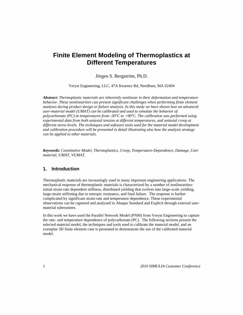
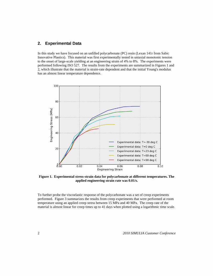
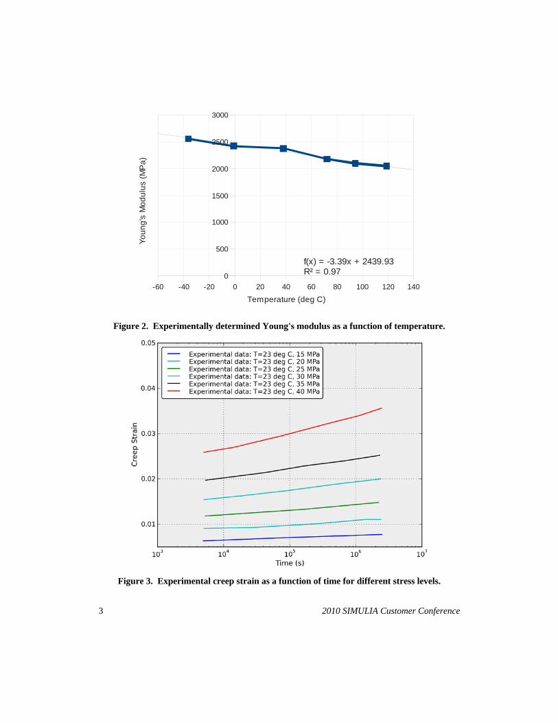
In this study we have focused on an unfilled polycarbonate (PC) resin (Lexan 141r from Sabic Innovative Plastics). This material was first experimentally tested in uniaxial monotonic tension to the onset of large-scale yielding at an engineering strain of 4% to 8%. The experiments were performed following ISO 527. The results from the experiments are summarized in Figures 1 and 2, which illustrate that the material is strain-rate dependent and that the initial Young's modulus has an almost linear temperature dependence.
Figure 1. Experimental stress-strain data for polycarbonate at different temperatures. The applied engineering strain rate was 0.01/s.
To further probe the viscoelastic response of the polycarbonate was a set of creep experiments performed. Figure 3 summarizes the results from creep experiments that were performed at room temperature using an applied creep stress between 15 MPa and 40 MPa. The creep rate of the material is almost linear for creep times up to 41 days when plotted using a logarithmic time scale.
3 2010 SIMULIA Customer Conference
-60 -40 -20 0 20 40 60 80 100 120 1400
500
1000
1500
2000
2500
3000
f(x) = -3.39x + 2439.93R² = 0.97
Temperature (deg C)
Youn
g's
Mod
ulus
(MPa
)
Figure 2. Experimentally determined Young's modulus as a function of temperature.
Figure 3. Experimental creep strain as a function of time for different stress levels.
4 2010 SIMULIA Customer Conference
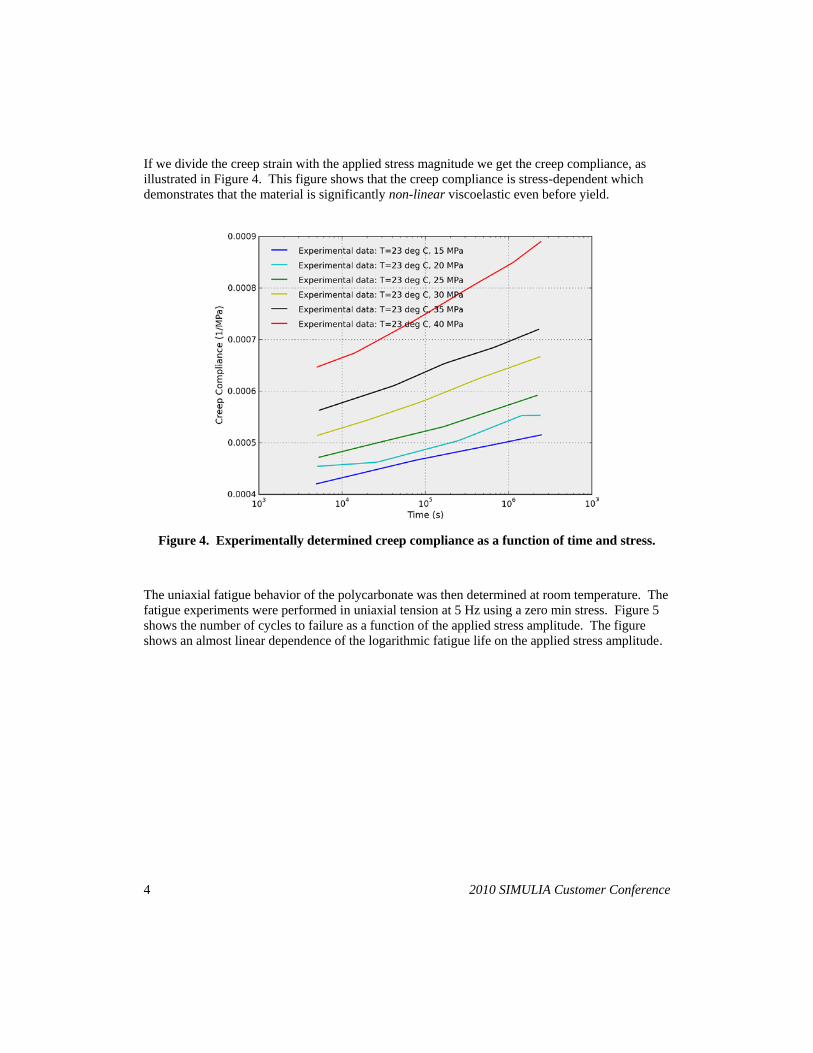
If we divide the creep strain with the applied stress magnitude we get the creep compliance, as illustrated in Figure 4. This figure shows that the creep compliance is stress-dependent which demonstrates that the material is significantly non-linear viscoelastic even before yield.
Figure 4. Experimentally determined creep compliance as a function of time and stress.
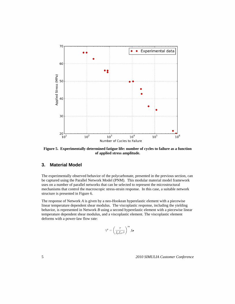
The uniaxial fatigue behavior of the polycarbonate was then determined at room temperature. The fatigue experiments were performed in uniaxial tension at 5 Hz using a zero min stress. Figure 5 shows the number of cycles to failure as a function of the applied stress amplitude. The figure shows an almost linear dependence of the logarithmic fatigue life on the applied stress amplitude.
5 2010 SIMULIA Customer Conference
Figure 5. Experimentally determined fatigue life: number of cycles to failure as a function of applied stress amplitude.
3. Material Model
The experimentally observed behavior of the polycarbonate, presented in the previous section, can be captured using the Parallel Network Model (PNM). This modular material model framework uses on a number of parallel networks that can be selected to represent the microstructural mechanisms that control the macroscopic stress-strain response. In this case, a suitable network structure is presented in Figure 6.
The response of Network A is given by a neo-Hookean hyperelastic element with a piecewise linear temperature dependent shear modulus. The viscoplastic response, including the yielding behavior, is represented in Network B using a second hyperelastic element with a piecewise linear temperature dependent shear modulus, and a viscoplastic element. The viscoplastic element deforms with a power-law flow rate:

6 2010 SIMULIA Customer Conference
where γp is the magnitude of the viscoplastic flow rate, τ is the driving shear stress, m is a material parameter, fp=1, fθ is a piecewise linear temperature-dependent factor, and fε is a factor controlling the exponential yield evolution:
where ff and ε^ are material parameters, and εpmax
The rate kinematics of the material model implementation is similar in structure to other viscoplastic material models (Bergstrom 2001, Bergstrom 2004).
is the maximum plastic strain that the material point has experienced.
Figure 6. Micromechanical representation of the selected material model.
To predict failure, a damage accumulation model was added to the material model. The selected damage model is based on Mises stress driving the damage accumulation:
In this equation σe is the Mises stress, σref is a reference stress, and t0 is a time constant. At t=0 there is no damage and D(0)=0. Material failure is taken to occur once D > 1.

7 2010 SIMULIA Customer Conference
4. Results
The material model was calibrated to the experimental data using the MCalibration software from Veryst Engineering. This software takes the experimental data files and a specification of the desired PNM structure, and then automatically finds the set of material parameters that gives the most accurate fit of the experimental data. The calibrated material parameters are listed in Table 1.
Table 1. Summary of material parameters used in the FE analysis. The values in gray are not important for the model response.
Network A Neo-Hookean hyperelastic: [µ,κ] [174 MPa, 2000 MPa]
Network A temperature dependence: 5 pairs of [T, f] values
[(243 K, 0.64), (273 K, 0.53), (296 K, 0.76), (333 K, 0.67), (363 K, 0.60)]
Network B: Neo-Hookean hyperelastic: [µ,κ] [601 MPa, 2000 MPa]
Network B hyperelastic temperature dependence: 5 pairs of [T, f] values
[(243 K, 1.11), (273 K, 1.24), (296 K, 1.28), (333 K, 1.12), (363 K, 1.30)]
Network B flow: [ , m] [14.2 MPa, 33]
Network B flow evolution: [ff, ] [3.2, 0.0037]
Network B flow temperature dependence: 5 pairs of [T,f] values
[(243 K, 0.006), (273 K, 0.023), (296 K, 18.1), (333 K, 4243), (363 K, 12784)]
Damage accumulation model: [t0, σref [5e-6 s, 50 MPa, 1] , m]
A first example of the predictions from the calibrated material is shown in Figure 7. This figure shows that the material model accurately captures the influence of temperature on the yielding behavior.

8 2010 SIMULIA Customer Conference
Figure 7. Comparison between uniaxial monotonic experimental data and predictions from the parallel network model (PNM).
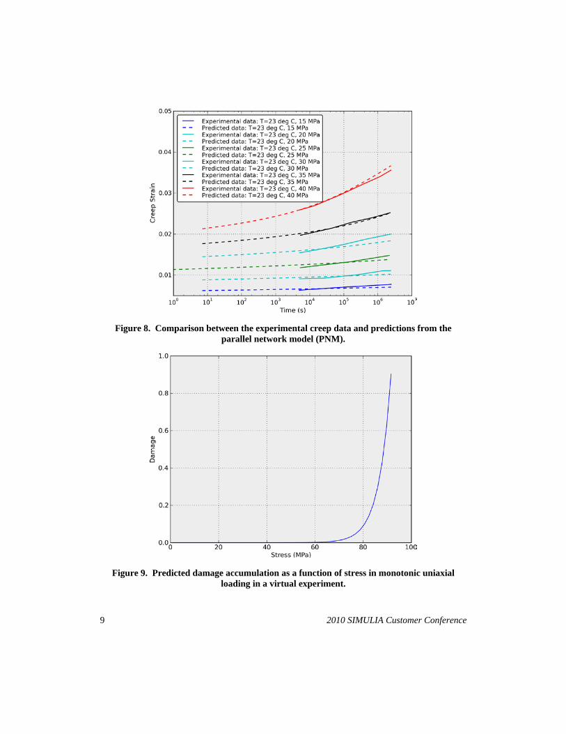
Figure 8 shows a comparison between the experimental creep data and the model predictions. Also in this case the experimental data is accurately predicted. It is interesting to note that the material model captures the nonlinear viscoelastic behavior at the different stress levels.
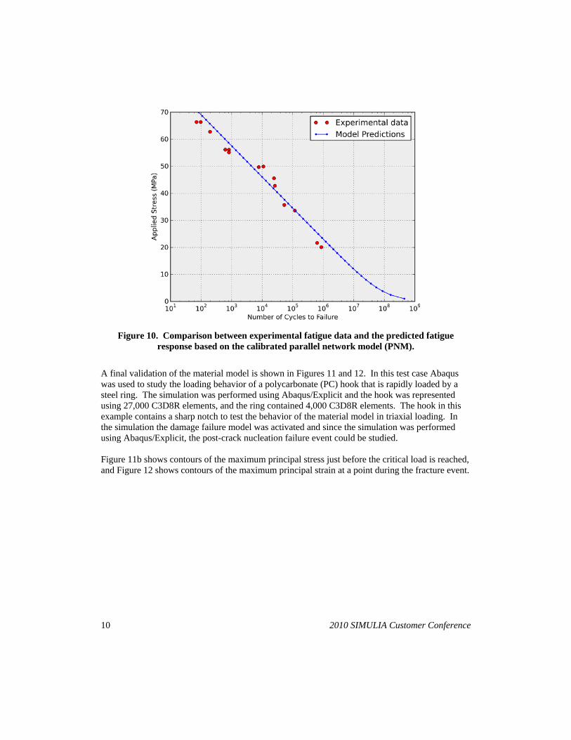
The calibrated damage model can be used to predict material failure during both monotonic and cyclic loading. Figure 9 shows the growth in damage as a function of applied stress magnitude in monotonic loading. In the damage model the failure is taken to occur once the damage level reaches a value of 1. A perhaps more interesting case is shown in Figure 10 illustrating that the material model can predict the experimentally observed fatigue behavior.
9 2010 SIMULIA Customer Conference
Figure 8. Comparison between the experimental creep data and predictions from the parallel network model (PNM).
Figure 9. Predicted damage accumulation as a function of stress in monotonic uniaxial loading in a virtual experiment.
10 2010 SIMULIA Customer Conference
Figure 10. Comparison between experimental fatigue data and the predicted fatigue response based on the calibrated parallel network model (PNM).
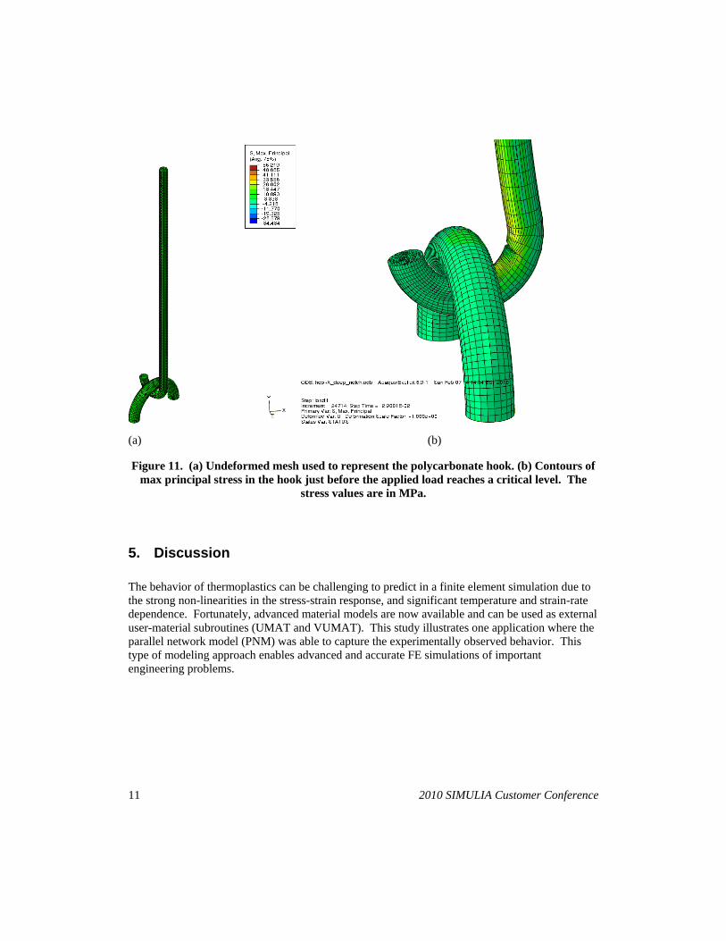
A final validation of the material model is shown in Figures 11 and 12. In this test case Abaqus was used to study the loading behavior of a polycarbonate (PC) hook that is rapidly loaded by a steel ring. The simulation was performed using Abaqus/Explicit and the hook was represented using 27,000 C3D8R elements, and the ring contained 4,000 C3D8R elements. The hook in this example contains a sharp notch to test the behavior of the material model in triaxial loading. In the simulation the damage failure model was activated and since the simulation was performed using Abaqus/Explicit, the post-crack nucleation failure event could be studied. Figure 11b shows contours of the maximum principal stress just before the critical load is reached, and Figure 12 shows contours of the maximum principal strain at a point during the fracture event.
11 2010 SIMULIA Customer Conference
(a) (b)
Figure 11. (a) Undeformed mesh used to represent the polycarbonate hook. (b) Contours of max principal stress in the hook just before the applied load reaches a critical level. The
stress values are in MPa.
5. Discussion
The behavior of thermoplastics can be challenging to predict in a finite element simulation due to the strong non-linearities in the stress-strain response, and significant temperature and strain-rate dependence. Fortunately, advanced material models are now available and can be used as external user-material subroutines (UMAT and VUMAT). This study illustrates one application where the parallel network model (PNM) was able to capture the experimentally observed behavior. This type of modeling approach enables advanced and accurate FE simulations of important engineering problems.

12 2010 SIMULIA Customer Conference
Figure 12. Contours of max principal strain during the failure of the polycarbonate hook.
6. References
[1] The Parallel Network Model (PNM) and the MCalibration software are commercially available from Veryst Engineering (http://www.veryst.com/PolyUModLibrary.html).
[2] J.B. Bergstrom, M.C. Boyce, “Constitutive Modeling of the time-dependent and cyclic loading of elastomers and application to soft biological tissues,” Mechanics of Materials, Vol. 33, pp. 523-530, 2001.
[3] J.S. Bergstrom, C.M. Rimnac, S.M. Kurtz, “An Augmented Hybrid Constitutive Model for Simulation of Unloading and Cyclic Loading Behavior of Conventional and Highly Crosslinked UHMWPE,” Biomaterials, Vol. 25, pp. 2171-2178, 2004.