Embed Size (px)
Citation preview

________________________________________
*Author for correspondence; E-mail: [email protected]
Int. J. Chem. Sci.: 14(4), 2016, 2787-2798 ISSN 0972-768X
www.sadgurupublications.com
FINITE ELEMENT METHOD ANALYSIS OF RECTANGULAR PLATE WITH CIRCULAR HOLE USING ANSYS
PRAVIN PAWAR*, RAJ BALLAV and AMARESH KUMAR
Department of Manufacturing Engineering, National Institute of Technology, JAMSHEDPUR (Jharkhand) INDIA
ABSTRACT
The geometrical irregularities provided with elements, which are used in machining. These irregularities disturb the stress distribution. In this study, the stress distribution of rectangular plate having a circular hole is analyzed. The two different materials are used for this analysis and results compared with one another to get an idea about stress distribution and deformation for the designing of the machine. From the present investigation, it can be concluded that the maximum stress occurs at corners of holes in both materials. Also, for both materials, it is observed that, as T/D ratio increases, it also increases stress concentration factor. The stress concentration factor values obtained from finite element analysis shows the maximum error of 0.33% for magnesium alloy and 0.30% for polyethylene, which is very minor. Thus, from the present study, it can be said that finite element analysis is a very effective tool to determine stresses induced in various materials.
Key words: Finite element method, ANSYS, Magnesium alloy, Polyethylene, Rectangular plate with hole.
INTRODUCTION
The elements, which are used for machining purposes offered with geometrical irregularities, which disturb the stress distribution and therefore, the state of stress in stress concentrated regions cannot be described in machine elements. Thus, the finite element method (FEM) is an important tool used to analyze the stress1. The finite element method (FEM) is a numerical method of analysis for stresses and deformations in structures of any given geometry. The structure is discretized into the so-called ‘finite elements’ connected through nodes. The type, arrangement and a total number of elements affect the accuracy of the results2. It is frequently used to solve the difficult engineering problems, mostly in the fields of mechanical, civil, and aeronautical engineering3. Also, it is a solution of several other types of engineering problems like heat conduction, fluid dynamics, electric and

P. Pawar et al.: Finite Element Method Analysis of…. 2788
magnetic fields, structure analysis, solid mechanics, dynamics, thermal analysis, electrical analysis, biomaterials.4,5
Magnesium alloys are mixtures of magnesium with other metals (called an alloy), often silicon, copper, aluminum, zinc, manganese, rare earth, and zirconium. While, a polymer of ethylene is a partially crystalline thermoplastics, which is resistant to chemicals and moisture, have good insulating properties, and are used especially in packaging and insulation. The magnesium alloy and polyethylene both are lightweight and have excellent properties due to which they have a wide range of applications. The magnesium alloy finds so many uses in the field of automobiles and aircraft. Whereas, polyethylene applied in equipment, home appliances, cutlery, fuel tanks, containers, agricultural tanks, highway barriers and water and waste water tanks. In general, the rectangular plate having a central hole is a common structure, but stress concentration around the hole makes the material liable to failure across the hole region. There are many solutions to reduce the stress concentration includes providing relief notches, holes etc.6,7
Many research activities are carried out in this field by different researchers. Dhanjal and Arora1 analyzed a rectangular plate with a circular hole at the center is by using finite element analysis. They observed that the SCF increases with increase in T/D ratio whereas, von Mises stress decreases with increase in T/D ratio. Shivlinges et al.2 studied SCF’s depend on the dimension ratio defined as the hole diameter of the beam to the width of the beam. Mekalke et al. (2012)3 investigated a plate with a circular hole applied to a uniform stress and examined the deviation in the results obtained through different meshes. Also, Brahmbhatt et al.4 analyzed rectangular plate with a central elliptical hole using ANSYS. They concluded that lower values of aspect ratio, stress intensity factor gives less error.
Jain5 calculated stresses and deflection in rectangular isotropic and orthotropic plates having a central circular hole under transverse static loading. Shaik and Mirzana6 calculated stress analysis around the circular hole made up of different materials using ANSYS. They found that stress concentration is always taking place on hole boundary in a finite width plate with a central hole under in static loading. Endigeri and Mannur7 concluded that introduction of auxiliary holes on either side by with composite plate decreased stress concentration factor. Mallikarjun et al.8 observed that maximum stress ratio increases with the increase of the angle of obliquity.
Thus, nowadays, there is a requirement of information about the stress concentration in designing the structure component. Although, the majorities of service cracks occurred in the area of stress concentration at the edge of a hole. In this investigation, the stress distribution of circular holes plate with different materials is carried out and results compared

Int. J. Chem. Sci.: 14(4), 2016 2789
with one another to get an idea about stress distribution and deformation for the designing of the machine.
Problem definition
For present work, a rectangular plate of material magnesium alloy and polyethylene has to be taken for calculating stresses induced and deformations produced due to the applied load. Also, the effect of T/D ratio i.e. ratio of the thickness of the plate has been analyzed by using four T/D ratios which are 0.4, 0.6, 0.8 and 1.0. The stress concentration factor has to be calculated for both methods i.e. analytical method and finite element method using ANSYS and the results were compared with one another. The material properties are shown in Table 1. Fig. 1 shows the boundary condition of given rectangular plate with a circular hole.
Table 1: Materials properties
Material Density Young's modulus
MPa
Yield strength
MPa
Poisson's ratio
Bulk modulus
MPa
Shear modulus
MPa
Magnesium alloy 1.8e-6 kg mm^-3 45000 193 0.35 50000 16667
Polyethylene 9.5e-7 kg mm^-3 1100 33 0.42 2291.7 387.32
Fig. 1: Boundary conditions of rectangular plate with circular hole
Analytical method
The present investigation deals with the study of the rectangular plate having a circular hole subjected to a uniform stress. The plate length of 300 mm, thickness is varied from T = 4, 6, 8, 10 mm, width W = 60 mm, with a hole of diameter d = 10 mm. and an

P. Pawar et al.: Finite Element Method Analysis of…. 2790
applied uniform stress of σ0 = 1000 N to the both sides. The stress concentration factor is evaluated using following theoretical formula3 –
Stress concentration factor (Kt) = 3.0 – 3.13(d/W) + 3.66(d/W)2 – 1.53(d/W)3 …(1)
Stress concentration factor (Kt) = 3 – 3.13(10/60) + 3.66(10/60)2 – 1.53(10/60)3
Kt = 1.6067
Finite element method
The finite element method analysis is executed in popular FEA package ANSYS 13. The model of the geometry is produced and analyzed in ANSYS. The force is applied on both sides of the plate. The model is meshed with solid 84 elements and having 728 total nodes. This element has the capabilities like plasticity, creep, stress stiffening, large deflections etc.1 The Fig. 2 shows that CAD model of rectangular plate with hole and Fig. 3 shows that meshed body of rectangular plate with hole.
Fig. 2: CAD model of rectangular plate with hole
Fig. 3: Meshed body of rectangular plate with hole

Int. J. Chem. Sci.: 14(4), 2016 2791
The stress concentration factor for a rectangular plate of finite width and centered circular hole is given by the following equation1,3.
Stress concentration factor (Kt) = stress Normal σ
stress Maximum σ
Whereas σmax is the maximum stress, which is likely to occur near the irregularity whereas σnom is the nominal stress in the member.
However, σnormal is calculated by following equation1, 3.
σ Normal = AF
Areaforce Applied
=
Area of plate (A) = (W × T) – (π/4 × d2)
= (60 × 4) – (π/4 × 102)
= 161.5 mm2
σ Normal = 2mm 161.5N 1000
σ Normal 4 mm = 6.1919 MPa
σ Normal 6 mm = 3.552 MPa
σ Normal 8 mm = 2.490 MPa
σ Normal 10 mm = 1.9175 MPa
Stress concentration factor (Kt) = valuestress Normal σ
valueAnsys stress Maximum σ …(2)
Kt for magnesium alloy = 1919.6035.11
Kt for magnesium alloy 4 mm = 1.7821
Kt for magnesium alloy 6 mm = 2.0644
Kt for magnesium alloy 8 mm = 2.2017
Kt for magnesium alloy 10 mm = 2.280

P. Pawar et al.: Finite Element Method Analysis of…. 2792
Similarly,
Kt for polyethylene 4 mm = 1.7792
Kt for polyethylene 6 mm = 2.0598
Kt for polyethylene 8 mm = 2.1956
Kt for polyethylene 10 mm = 2.2730
Fig. 4: Equivalent (Von-mises) stress and deformations of magnesium alloy 4 mm
thickness rectangular plate
Fig. 5: Equivalent (Von-mises) stress and deformations of magnesium alloy 6 mm
thickness rectangular plate

Int. J. Chem. Sci.: 14(4), 2016 2793
Fig. 6: Equivalent (Von-mises) stress and deformations of magnesium alloy 8 mm
thickness rectangular plate
Fig. 7: Equivalent (Von-mises) stress and deformations of magnesium alloy 10 mm
thickness rectangular plate
Fig. 8: Equivalent (Von-mises) stress and deformations of polyethylene 4 mm thickness rectangular plate

P. Pawar et al.: Finite Element Method Analysis of…. 2794
Fig. 9: Equivalent (Von-mises) stress and deformations of polyethylene 6 mm thickness
rectangular plate
Fig. 10: Equivalent (Von-mises) stress and deformations of polyethylene 8 mm
thickness rectangular plate
Fig. 11: Equivalent (Von-mises) stress and deformations of polyethylene 10 mm thickness rectangular plate

Int. J. Chem. Sci.: 14(4), 2016 2795
Percentage error in theoretical and practical values = valuesalTheroretic
valuesFEM valueoretical The −
RESULTS AND DISCUSSION
The values of T/D ratio, maximum Von mises stress, maximum deformation and stress concentration factor are depicted in Table 2 for both the materials. The values of stress concentration factor is based on eq. (1) and eq. (2) are compared and error % is calculated, which is also depicted in Table 2. From the table, it is observed that in both materials, when the T/D ratio and stress concentration factor shows lower values at that time the von Mises stress and deformation values showed higher values. As compared to theoretical values of stress concentration factor, the factor values obtained by FEM shows good accordance in both materials. The magnesium alloy shows 0.33% and polyethylene shows 0.30% error between FEM and theoretical values for T/D ratio of 0.4.
Table 2: Parameters obtained from finite element analysis and theoretical values
T/D Ratio
Material Maximum
(Von) mises Stress (MPa)
Max Deformation
(mm)
Stress concentration factor Error
% FEM values
Theoretical values
0.4 Magnesium alloy
11.035 0.01401 1.7821 2.5729 0.33
0.6 7.333 0.00940 2.0644 2.5729 0.19
0.8 5.4823 0.00705 2.2017 2.5729 0.14
1.0 4.3727 0.00564 2.280 2.5729 0.11
0.4 Polyethylene 11.017 0.57766 1.7792 2.5729 0.30
0.6 7.3167 0.38511 2.0598 2.5729 0.19
0.8 5.4672 0.28883 2.1956 2.5729 0.14
1.0 4.3586 0.23107 2.2730 2.5729 0.11
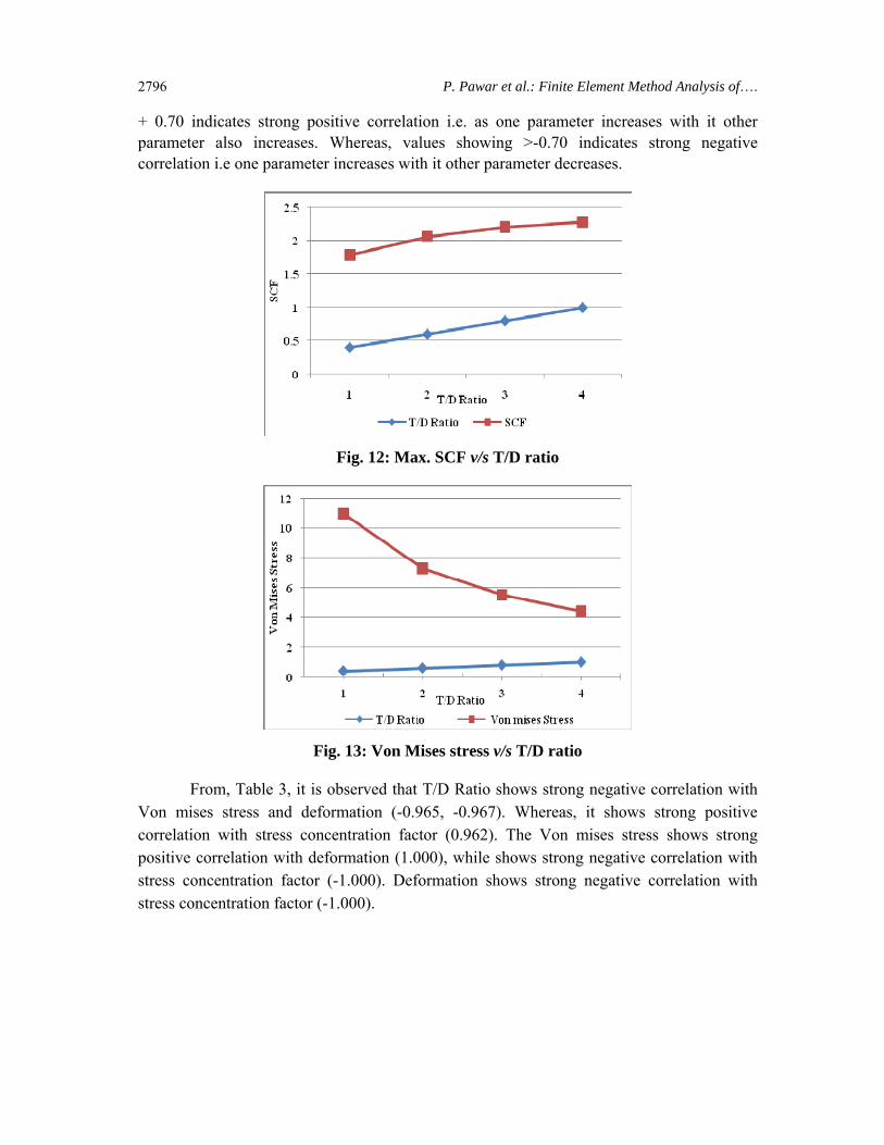
The graphical presentation of variations in T/D ratio, Von mises stress and stress concentration factor of both the materials is represented in Figs. 12 and 13.
Also, for the detailed study of the relations between T/D ratio, Max Von mises stress, deformation and stress concentration factor, the statistical analysis i.e. Correlation coefficient, is carried out, which is shown in Table 3. According to it, the values showing >
P. Pawar et al.: Finite Element Method Analysis of…. 2796
+ 0.70 indicates strong positive correlation i.e. as one parameter increases with it other parameter also increases. Whereas, values showing >-0.70 indicates strong negative correlation i.e one parameter increases with it other parameter decreases.
Fig. 12: Max. SCF v/s T/D ratio
Fig. 13: Von Mises stress v/s T/D ratio
From, Table 3, it is observed that T/D Ratio shows strong negative correlation with Von mises stress and deformation (-0.965, -0.967). Whereas, it shows strong positive correlation with stress concentration factor (0.962). The Von mises stress shows strong positive correlation with deformation (1.000), while shows strong negative correlation with stress concentration factor (-1.000). Deformation shows strong negative correlation with stress concentration factor (-1.000).

Int. J. Chem. Sci.: 14(4), 2016 2797
Table 3: Correlation coefficient between different parameters obtained from finite element analysis
T/D
Ratio
Max von mises stress
(MPa)
Max Deformation
(mm)
Stress concentration
factor
T/D Ratio 1
Max Von mises stress (MPa) -0.965 1
Max deformation (mm) -0.967 1.000 1
Stress concentration factor 0.962 -1.000 -1.000 1
CONCLUSION
From the present investigation, it can be concluded that the maximum stress occurs at corners of holes in both materials. Also, for both materials, it is observed that The deformation decreases with increase in T/D ratio, while an increase in T/D ratio resulted into a decrease in von Mises stress and as T/D ratio increases with increase in stress concentration factor. The stress concentration factor values obtained from finite element analysis shows a maximum error of 0.33% for magnesium alloy and 0.30% for polyethylene, which is very minor. Thus, from the present study, it can be said that finite element analysis is a very effective tool to determine stresses induced in various materials.
REFERENCE
1. S. Dhanjal and R. Arora, Stress Analysis of a Rectangular Plate with Circular Hole Using Three Dimensional Finite Element Model, Int. J. Engg., Business and Enterprise Applications (IJEBEA), 1(12), 77-80 (2015).
2. Shivlingesh, S. B. Kivade, B. Mallikarjun. FEA Analysis of Stresses for Cantilever Beam with Hole Subjected to Different Mode of Loading Systems, Int. J. Adv. Engg. Technol., Manage. Appl. Sci., 3(1), 116-126 (2016).
3. G. C. Mekalke, M. V. Kavade and S. S. Deshpande, Analysis of a Plate with a Circular Hole by FEM, IOSR J. Mech. Civil Engg. (IOSR-JMCE), 1(5), 25-30 (2012).
4. D. Brahmbhatt, K. Brahmbhatt and D. Patel, Stress Concentration Factor Converts Into Stress Intensity Factor using ANSYS, European J. Adv. Engg. Technol., 2(1), 46-49 (2015).

P. Pawar et al.: Finite Element Method Analysis of…. 2798
5. N. K. Jain, Analysis of Stress Concentration and Deflection in Isotropic and Orthotropic Rectangular Plates with Central Circular Hole under Transverse Static Loading, Int. J. Mech., Aerospace, Industrial, Mechatronic and Manufacturing Engineering, 3(12), 1513-1519 (2009).
6. A. S. Shaik and I. M. Mirzana, Stress Concentration of Rectangular Plate with a Hole Made With Composite Material Using Finite Element Analysis, IOSR J. Mech. Civil Engg. (IOSR-JMCE), 13(4), 01-05 (2016).
7. B. R. Endigeri and V. Mannur, Fem for Stress Reduction by Optimal Auxiliary Holes in a Uniaxially Loaded Composite Plate, Proceedings of International Conference on Research in Electrical, Electronics & Mechanical Engineering, Dehradun, 1-5 26th April (2014).
8. B. Mallikarjun, P. Dinesh and K. I. Parashivamurthy, Finite Element Analysis of Elastic Stresses Around Holes in Plate Subjected to Uniform Tensile Loading, Bonfring Int. J. Indust. Engg. Manage. Sci., 2(4), 136-142 (2012).
Revised : 31.10.2016 Accepted : 03.11.2016