Embed Size (px)
Citation preview
IJME • January-June 2013 • Volume 6 • Issue 1
Finite Element Development for Analysis of Smart Structures 41
*corresponding author: [email protected]
Finite Element Development for Analysis of Smart Structures
Chandrashekhar Bendigeri1*, K. Badari Narayana2 & K. Ramachandra31Asst. Professor, Dept of Mechanical Engg, UVCE, Bangalore University, Bangalore
2Goodrich Aerospace Service Pvt Ltd, white field road, Bangalore3Director (Ex), G T RE, Bangalore
ABSTRACT: In the present study, a numerical solution based on the finite element method has been developed to analyzethe deformation, electric potentials of a piezoelectric smart structure subjected to external mechanical or electrical loadings.The formulation of the finite element for static analysis has been presented based on isoparametric formulation. Theelement considered in the present study is eight noded hexahedral elements. A computer code based on the aboveformulation has been developed using MATLAB software to solve the three dimensional structures integrated withpiezoelements. The experiments have been conducted on the piezoelectric smart structures consisting carbon epoxy beamand the results obtained were used for validating the present finite element code developed and found to have goodagreement
Keywords: Smart structures, Piezoelectric, Finite Element and MATLAB
1. INTRODUCTION
Piezoelectric materials are widely used in smart structureapplication due to their high bandwidth, high outputforce, and compact size. The effective use of such materialon different application can be done if their behavior iswell understood [1-3]. The Finite element method canbe used so that number of iteration can be done tounderstand and optimize the process. The effectivenumerical and experimental methods are needed toevaluate behavior and applications of piezoelectricstructures subjected to electromechanical loading [4-7].In the present work formulation of a finite element hasbeen done. The implementation of the formulation hasbeen done using MATLAB software. The developed codeis validated using number of problems involvingdifferent materials such as isotropic, orthotropic andpiezoelectric materials and a combination of thesematerials. One such example is piezo electric actuationof carbon epoxy beam has been discussed in detail inthis paper. The present solution are compared with resultobtained by experimental approaches
2. CONSTITUTIVE EQUATIONS
The basic constitutive equations for the linear theory ofpiezoelectric are as follows [8]
{�} = [C] {�} – [d] {E}
{D} = {d}T {�} + [b] {E} (1)
where {�}= {�11, �22, �33, �23, �13 & �12}T is the stress vector,
{�} = {�11, �22, �33, �23, �13 & �12}T Strain tensor, {E} = {E1, E2
& E3} the electric field, {D} = {D1, D2, & D3}, the electricdisplacement or Electric flux density vector, [C] theelasticity constants matrix, [b] the dielectric constantsmatrix, [d] the piezoelectric coupling coefficients matrixor Piezoelectric constants.
3. FINITE ELEMENT MODELING OFPIEZOELECTRIC MATERIAL USING 3D
HEXAHEDRAL ELEMENT
In the finite element formulation [9-10], thedisplacements u, v, w and the potentials areapproximated as functions of the nodal displacementsun and nodal potential �n where n is node number of theelement and the nodal shape functions Ni such that
{u} = [Nu] {un}{�} = [N�] {�n} (2)
The electric field vector of an element is representedas follows
{E} = < Ex, Ey, Ez >T (3)
where
Ei = –�i (4)
Consequently
{�} = [Bu] {un}
{E} = –[B�] {�n} (5)
The matrix [Bu] and [B�] contains the derivatives ofthe shape functions for the displacements and potentialswhich is written as follows
IJME • January-June 2013 • Volume 6 • Issue 1
42 Chandrashekhar Bendigeri, K. Badari Narayana & K. Ramachandra
][
0
0
0
00
00
00
][ u
xy
xz
yz
z
y
x
u NB
��������
�
�
��������
�
�
��
��
���
��
�(6)
][][ u
z
y
x
NB���
�
�
���
�
�
�
�
�
�� (7)
The external virtual work done by the externalmechanical and electrical forces is
{ }
{ }
emech n
eelect n
W u F
W Q
� �� � �
� �� �� � (8)
Where {F}, {Q} are external mechanical force andelectrical charge vectors. Consequently, mechanical andelectrical equilibrium equations can be written as follows
[ ] ([ ][ ]{ } [ ][ ]{ }) { }Tn u u n n nu B c B u d B dV u F�� � � � � �� � ��
(9)
and
[ ] ([ ] [ ] { } [ ][ ]{ }) { }T Tn u n n nB d B u b B dV Q� �� �� � � � �� �� ��
(10)or
( [ ] [ ] [ ] ){ } ( [ ] [ ] [ ] ){ } { }
( [ ] [ ] [ ] ){ } ( [ ] [ ][ ] ){ } { }
T Tu u n u n
T T Tu n n
B c B dV u B d B dV F
B d B dV u B b B dV Q
�
� � �
� � �
� � � �
� �� �
(11)
The stiffness matrices are defined as follows
[ ] [ ] [ ] ]
[ ] [ ] [ ] ]
[ ] [ ] [ ] ]
[ ] [ ]
Tuu u uv
T
v
T Tu uv
Tu u
K B c B dV
K B b B dV
K B d B dV
K K
�� � �
� �
� �
�
� �
�
�
��� (12)
[ ]{ } [ ]{ } { }
[ ]{ } [ ]{ } { }uu n u n
u n n
K u K F
K u K Q�
� ��
� � �
� � �
[ ] [ ] { } { }
[ ] [ ] { } { }uu u n
u n
K K u F
K K Q�
� ��
� � � � � ��� � � �� � �� � � �� �
(13)
[K] {u} = {F} (14)
The above equations are included in formulation ofelement to add the capability for analyses of piezoelectricsmart structures and the same is coded using MATLABsoftware.
4. EXPERIMENTS CONDUCTED USINGPIEZOELECTRIC MATERIAL
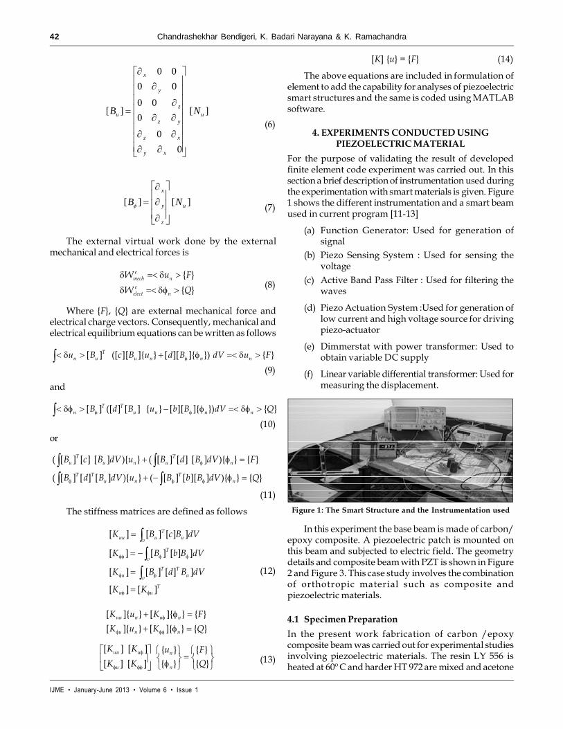
For the purpose of validating the result of developedfinite element code experiment was carried out. In thissection a brief description of instrumentation used duringthe experimentation with smart materials is given. Figure1 shows the different instrumentation and a smart beamused in current program [11-13]
(a) Function Generator: Used for generation ofsignal
(b) Piezo Sensing System : Used for sensing thevoltage
(c) Active Band Pass Filter : Used for filtering thewaves
(d) Piezo Actuation System :Used for generation oflow current and high voltage source for drivingpiezo-actuator
(e) Dimmerstat with power transformer: Used toobtain variable DC supply
(f) Linear variable differential transformer: Used formeasuring the displacement.
Figure 1: The Smart Structure and the Instrumentation used
In this experiment the base beam is made of carbon/epoxy composite. A piezoelectric patch is mounted onthis beam and subjected to electric field. The geometrydetails and composite beam with PZT is shown in Figure2 and Figure 3. This case study involves the combinationof orthotropic material such as composite andpiezoelectric materials.
4.1 Specimen Preparation
In the present work fabrication of carbon /epoxycomposite beam was carried out for experimental studiesinvolving piezoelectric materials. The resin LY 556 isheated at 60º C and harder HT 972 are mixed and acetone

IJME • January-June 2013 • Volume 6 • Issue 1
Finite Element Development for Analysis of Smart Structures 43
is added to the mixture of resin and hardeners to achieverequired consistency. The carbon fibers in fabric formwill be used as reinforcement with 60% volume fraction.The impregnations of the fabric are carried out on aheated plate at 60º C and the entrapped air was removedwith help of rollers. The curing is done for 3 hrs under120º C and pressure of 7 bars and a post curing for 1 hrat 180º C. Then it is cut to required shape using diamond-cutting equipment. The composite is a cross plylamination and the fibers orientation angles in thealternative layers are 0°/90°/0°/90°.
The piezoelectric actuator is bonded on to compositebeam after cleaning the surface and marking the position.The leads of the pig tail provided with the piezoelectricmaterials are connected to the instruments by usinganother terminal and the specimen is clamped to conductthe experiment.
• The variable DC supply (Dimmerstat withpower transformer, variable DC supply 0-200Vand 1A) is applied to PZT on the beam
• The supplied voltage to the PZT on beam causesit to deflect.
• The deflection thus obtained at tip the beam ismeasured using linear variable differentialtransformer
5. FINITE ELEMENT ANALYSIS
The finite element model of the smart beam with sameconfiguration as that of the beam used in experiment isconsidered for the purpose of comparison. The finiteelement model of the composite beam is shown in theFigure 5. The convergence studies are carried out byincreasing the number of elements in the finite elementmesh. The results of finite element model consisting of260 elements and 501 nodes and the experimental resultsare given in the Table 1. The results of present code arein good agreement with experimental results.
Figure 2: Geometric Details
Figure 3: Composite Beam with PZT Actuator
4.2 Experimental Procedure
The block diagram of the experiment is similar to oneshown in the Figure 4.
The procedure for conducting the experiment is asfollows:
• The composite beam with piezoelectric materialis clamped tightly at one side as cantilever.
Figure 4: The Block Diagram of the Experiment forSmart Beam
DisplacementIndicator
VariableD C Supply
Piezo
LVDT
Figure 5: Finite Element Model
Table 1Comparison of Deflection of Smart Carbon Composite Beam
Sl. No. Voltage applied Deflection (µ m)(Volts) Experiment Present code
1 50 16 15.7
2 100 31 30.6
3 150 46 45.3
4 200 61 60.4
6. CONCLUSIONS
The finite element code for analysis of smart structuresis developed using MATLAB programming language.Also experiment was carried out on the smart carbonepoxy beam with piezoelectric material attached andrelated instruments are discussed. Simple experimentsare devised to obtain static behaviour of the smartstructure. These experimental results were also usefulto validate the present code. The developed code isvalidated by comparing the results of experiments
IJME • January-June 2013 • Volume 6 • Issue 1
44 Chandrashekhar Bendigeri, K. Badari Narayana & K. Ramachandra
carried out by using piezoelectric material in combinationwith orthotropic materials such as composite. The finiteelement code developed for structure analysis andelectromechanical analysis of the smart compositestructure is found to have good agreement with theexperimental results.
REFERENCES[1] P. F. Gobin and J. Jayet, “Recent Aspects of French Research
on Intelligent Materia ls and Systems”, InternationalConference on Smart Materials, Structures and Systems, 7-10 July, 1999.
[2] Sung kyu and Charles Keillers, “Finite Element Analysis ofComposite Structures Containing Distributed PiezoceramicSensors and Actuators” AIAA J, 30 (3), (1992).
[3] Bahu Sun and Dahuang, “Vibration Suppression ofLaminated Beams with a Piezoelectric Damping Layer”,Composite Structures, 53, (2001), 437-447.
[4] Chen Chang-Quing and Wang Xiao –Ming, “Finite ElementApproach of Vibration Control using Self-SensingPiezoelectric Actuators”, Computers and Structures, 60 (3),(1998).
[5] Benjeddou, and A. Trindade, “New Shear Actuated SmartStructure Beam Finite Element”, AIAA J, 37(3), (1999).
[6] B. L. Wang and N. Noda, “Design of Smart FunctionallyGraded Thermo-Piezoelectric Composite Structure”, J. ofSmart Materials and Structures, 10, (2001).
[7] S. Y. Wang, S. T. Quek and K. K. Ang, “Vibration Control ofSmart Piezoelectric Composite Plates”, J. of Smart Materialsand Structures, 10, (2001), 637-644.
[8] IEEE std, 1988, “IEEE Standard on Piezoelectricity–ANSI/IEEE Std 176”, (1987).
[9] J. G. Smits, S. I. Dalke, and T. K. Cooney, “The ConstituentEquations of Piezoelectric Bimorphs,” Sensors and ActuatorsA, 28, (1991), 41–61.
[10] E. F. Crawley and K. B. Lazarus, 1991 “Induced StrainActuation of Isotropic and Anisotropic plate”, AIAA Journal,29, 944 –951.
[11] Yao Fu, Erol C. Harvey, K. Muralidhar Ghantasala and Geoff,“Design, Fabrication and Testing of Piezoelectric PolymerPVDF Microactuators” J. of Smart Material and Structure, 15,(2006), 141–146.
[12] Piezo Film Sensors Technical Manual MeasurementSpecialties, Valley Forge August, 1998.
[13] Kekana and P. Tabakov, “Static Control of Composite Platesusing Piezoelectric Sensor and Actuator Techniques” J. ofSmart Material and Structure, 14, (2005), 349-353.