Embed Size (px)
Citation preview
FINITE ELEMENT ANALYSIS AND MODAL
ANALYSIS OF CAMSHAFT USING ANSYS
SOFTWARE
DISSERTATION- II
Submitted in Partial Fulfilment of the
Requirement for Award of the Degree
Of
MASTER OF TECHNOLOGY
In
MECHANICAL ENGINEERING
By
Dinesh Kumar
(11004966)
Under the Guidance of
Mr. Nitin Chauhan
DEPARTMENT OF MECHANICAL ENGINEERING
LOVELY PROFESSIONAL UNIVERSITY
PHAGWARA, PUNJAB (INDIA) -144411
2014 - 2015
i

LOVELY PROFESSIONAL UNIVERSITY
CERTIFICATE
I hereby certify that the work which is being presented in the Dissertation-II entitled
“Finite Element Analysis and Modal Analysis of Camshaft Using ANSYS Software”
partial fulfilment of the requirement for the award of degree of Master of Technology
and submitted in Department of Mechanical Engineering, Lovely Professional
University, Punjab is an authentic record of my own work carried out during period of
Dissertation under the supervision of Mr. Nitin Chauhan, Assistant Professor,
Department of Mechanical Engineering, Lovely Professional University, Punjab.
The matter presented in this Dissertation-II has not been submitted by me
anywhere for the award of any other degree or to any other institute.
Date: Dinesh Kumar
This is to certify that the above statement made by the candidate is correct to best
of my knowledge.
Date: Mr. Nitin Chauhan Supervisor M-Tech Dissertation-II examination of Finite Element Analysis and Modal Analysis of Camshaft Using ANSYS Software, has been held on
Signature of Examiner
ii

3
ACKNOWLEDGEMENTS
I owe my deepest gratitude and respect to my mentor Mr. Nitin Chauhan for his continuous
support and encouragement of this work. He is not only a knowledgeable and intelligent guide
and teacher, but also a responsible and considerate human being. I have wondered more than
once at his insight and Professionalism. I especially thank him for his understanding, patience,
and guidance during the project. I will always be grateful for what I learned from him during my
project.
It has been a great honour and privilege for me to know and work with my advisor. He is an
extremely knowledgeable teacher who appreciates Science for the sake of science, and makes
every effort to help his students see the beauty in learning and education. His modest and
friendly behaviour raises every admiration and respect. He has generously shared with me his
expertise and knowledge, and I are indebted to him for giving me the opportunity to talk to him
regularly and for reviewing my work under his intense time constraints. This work would by no
means be possible without his interesting ideas, insights, and suggestions.
I would like to extend my most sincere thanks to my friends at lovely professional university for
their group effort and friendship.
I would like to thank my wonderful friends in LPU and elsewhere for their encouragements, and
for making my project a memorable experience on the social front.
I am boundlessly grateful to my entire family for their love and never-ending support. I
especially thank my parents.
- Dinesh Kumar
____________________

4
TABLE OF CONTENTS
1 INTRODUCTION ...........................................................................................................................10
1.1 Classification: ..............................................................................................................................10
1.1.1 Hydraulic flat-tappet .................................................................................................. 10
1.1.2 Hydraulic Roller .......................................................................................................... 11
1.1.3 Solid Flat-tappet and Roller ....................................................................................... 11
1.2 Valve Train Sub-Assembly: .........................................................................................................12
2 REVIEW OF LITERATURE .............................................................................................................14
2.1 Outcomes: ..................................................................................................................................19
2.1.1 Summary: ................................................................................................................... 19
3 OBJECTIVE OF STUDY (PROBLEM FORMULATION) ................................................................21
3.1 SCOPE OF STUDY ........................................................................................................................21
3.2 EXPECTED OUTCOMES................................................................................................................21
4 RESEARCH METHODOLOGY .......................................................................................................22
4.1 Analysis Procedure .....................................................................................................................23
4.1.1 Planning the Analysis ................................................................................................. 23
4.1.2 Pre-Processor ............................................................................................................. 24
4.1.3 Creating the model .................................................................................................... 24
4.1.4 Applying a Mesh ......................................................................................................... 24
4.1.5 Apply Loads ................................................................................................................ 26
4.1.6 Applying Boundary Conditions .................................................................................. 26
4.1.7 Solution ...................................................................................................................... 27
4.1.8 Post-Processor ........................................................................................................... 27
5
4.2 Material used for the analysis: ...................................................................................................27
4.2.1 Cast iron: .................................................................................................................... 27
4.2.2 Structural steel: .......................................................................................................... 28
4.2.3 EN 8D steel ................................................................................................................. 29
4.2.4 EN 28 steel: ................................................................................................................ 30
4.2.5 EN 24 steel: ................................................................................................................ 30
4.3 Work Plan with Time ..................................................................................................................31
5 RESULTS AND DISCUSSION ........................................................................................................32
5.1 Total deformation in camshaft of different materials: ..............................................................32
Units used: 32
5.1.1 Loading conditions: .................................................................................................... 33
5.1.2 MODEL ....................................................................................................................... 36
5.1.3 For EN8D: ................................................................................................................... 36
5.1.4 For Cast iron: .............................................................................................................. 37
5.1.5 For EN 24 .................................................................................................................... 38
5.1.6 For structural steel: .................................................................................................... 39
5.2 Static structural analysis: ............................................................................................................39
5.3 Results: .......................................................................................................................................40
5.4 Analysis of camshaft in rotating conditions: ..............................................................................42
5.4.1 Boundary conditions: ................................................................................................. 42
5.5 MODAL ANALYSIS OF CAMSHAFT: ..............................................................................................45
5.5.1 EN24: .......................................................................................................................... 46
5.5.2 END8: ......................................................................................................................... 46
5.5.3 Structural steel: .......................................................................................................... 47
5.5.4 Cast iron: .................................................................................................................... 47

6
5.6 Analysis procedure: ....................................................................................................................49
5.7 Validation: ..................................................................................................................................51
5.7.1 Problem description: .................................................................................................. 51
5.7.2 Analysis of the natural frequency of a shaft (no load condition): ............................. 51
5.8 Analytical solution: .....................................................................................................................53
5.8.1 Boundary conditions: ................................................................................................. 53
5.8.2 Results: ....................................................................................................................... 54
5.8.3 Conclusion: ................................................................................................................. 55
6 CONCLUSION ................................................................................................................................56
6.1 Results: .......................................................................................................................................57
6.2 Future scope: ..............................................................................................................................58
6.3 Recommendations ......................................................................................................................58
7 REFERENCES: ................................................................................................................................59

7
List of tables:
Table 1: Chemical composition of EN8D. .................................................................................................29
Table 2: Mechanical properties of EN8D ...................................................................................................29
Table 3: Chemical composition of EN28 ...................................................................................................30
Table 4: Chemical composition of EN24 ..................................................................................................30
Table 5: work plane with estimated time....................................................................................................31
Table 6: Engine specification for loading ...................................................................................................33
Table 7: Camshaft specifications. ...............................................................................................................33
Table 8: Valve and accessories specifications. ...........................................................................................34
Table 9: Details of the geometry used for FE analysis ...............................................................................36
Table 10: Showing the bounding box and the geometric properties for the model EN8D. ........................37
Table 11: Showing the bounding box and the geometric properties for the model cast iron .....................37
Table 12: Showing the bounding box and the geometric properties for the model EN24 .........................38
Table 13: Showing the bounding box and the geometric properties for the model structural steel. ..........39
Table 14 : Results - Total deformation, equivalent (von mises) stress and strain. .....................................40
Table 15: Showing the results for EN8D material. ....................................................................................42
Table 16: Showing the results for EN24 material. .....................................................................................42
Table 17: Showing the results for S.S material. .........................................................................................43
Table 18: Showing the results for Cast iron. ..............................................................................................43
Table 20 : Showing the natural frequencies and deformation with different modes of EN24 camshaft ....46
Table 21: Showing the natural frequencies and deformation with different modes of EN8D camshaft ....46
Table 22: Showing the natural frequencies and deformation with different modes of SS camshaft ..........47
Table 23: Showing the natural frequencies and deformation with different modes of cast iron camshaft .47
Table 24: Specifications of shaft ................................................................................................................51
Table 25: Boundary conditions applied ......................................................................................................52
Table 26: Boundary conditions of the shaft................................................................................................54
Table 27: Results showing the total deformation on various frequencies ..................................................54
Table 28: Comparison of theoretical and analytical values. .......................................................................55
8
List of figures:
Figure 1: The actual CAD model of camshaft ............................................................................................11
Figure 2: Showing the valvetrain assembly of engine head. ......................................................................12
Figure 3: Research methodology and steps included in research ...............................................................22
Figure 4: Analysis procedure and the steps involved in the process. .........................................................23
Figure 5: showing the CAD model of camshaft .........................................................................................32
Figure 6 : Showing the meshed wireframe and deformed wireframe of camshaft. ....................................36
Figure 7: showing the boundary conditions for the analysis ......................................................................39
Figure 8: Showing the total deformation of camshaft ................................................................................40
Figure 9: Equivalent stress (Von- mises) of camshaft ................................................................................41
Figure 10: Equivalent strain (Von mises) of the camshaft .........................................................................41
Figure 11 : Graph showing comparison between mass of different camshafts of different materials ........41
Figure 12: boundary conditions for the camshaft in rotating conditions. ...................................................42
Figure 13: Showing the equivalent (Von mises) stress in camshaft while rotating. ...................................44
Figure 14: Showing the total deformation in the camshaft while rotation in loading condition. ...............44
Figure 15: Showing the equivalent (Von mises) strain in camshaft while rotation. ...................................44
Figure 16: showing 6 mode shapes of camshaft with deformations ...........................................................48
Figure 17: Graph showing the comparison between the natural frequencies of different material camshaft
....................................................................................................................................................................49
Figure 18: Final deformed shape of camshaft. ...........................................................................................50
Figure 19: Showing the cad model of shaft ................................................................................................51
Figure 20: Mode shapes of shaft. ...............................................................................................................55
9
List of equations:
1.Force exerted by valve ............................................................................................................................. 34
2.Spring force ............................................................................................................................................. 34
3. Volume calculation:................................................................................................................................ 34
4. Gas force ................................................................................................................................................. 35
5. Deflection in shaft .................................................................................................................................. 35
6.Bending stress .......................................................................................................................................... 35
7. Moment of inertia of cylinder ................................................................................................................. 52
8.Natural Frequency (both ends fixed) ....................................................................................................... 52
9.Natural frequency (both ends are supported) .......................................................................................... 52
10. Natural frequency (both ends are freed) ............................................................................................... 53
Nomenclature:

10
CHAPTER -1
1 INTRODUCTION
In internal combustion engine camshaft is use to transfer motion between inlet and exhaust
valve. Since the opening and closing of valves is so important in IC engine therefore it is very
important to optimize the component which is providing that motion if the motion is not precise
then the performance of engine will be degrade. Therefore it is very important to analyse the
component that includes the mathematical behaviour and model of the physical model. In this
case, introduction of two mass, single degree of freedom and multiple degree of freedom
dynamic models of cam follower systems are studied. For a Four stroke engine camshaft is the
most important component in the performance of engine. Camshaft is such an important part of
engine that the researchers have spent years to design a precise and accurate camshaft that may
transfer the exact motion to the valves. In the presented work the cause of fracture and the exact
loading conditions of camshaft are discussed. By using scanning electron microscopy and finite
element analysis methods are used for fracture analysis of camshaft. The camshaft rotates half
times the crankshaft or once per four-cycle stroke. The camshaft may operate the: Valve train,
Mechanical fuel pump, Oil pump, Distributor, Major function is to operate the valve train. The
lobes on the cam open the valves against the pressure of the valve springs. Bearing journal can
be internally or externally lubricated (oiled).
1.1 Classification:
Camshafts are of one of four types:
Hydraulic flat-tappet
Hydraulic roller
Solid flat-tappet
Solid roller
1.1.1 Hydraulic flat-tappet
The lifter is “spring” and oil loaded to allow for compensation. It is of Traditional O.E. style
(1950’s – mid 90’s).Used with flat or convex-faced lifters, generally cast iron or hardened steel
is used to made these camshafts. Requires a “break-in” period to establish a wear pattern. Cast-
iron cams are finished with a phosphate coating. These are mainly Steel cams (SAE 4160 or
4180) are hardened by Induction hardening – heated cherry-red in an electric field then oil

11
cooled. Liquid nitriding – hardens to .001 to .0015 Gas nitriding– hardens to .004 to .006
thickness.
Figure 1: The actual CAD model of camshaft
1.1.2 Hydraulic Roller
The camshaft is generally made of non-hardened steel. The lobes must be “finished” by the
manufacturer prior to assembly there is no “break-in period”.
1.1.3 Solid Flat-tappet and Roller
In solid flat tappet and roller camshaft No internal hydraulic absorption present in the material
of the cam allowing more consisting valve lift, especially at high RPM. It creates noise in low
temperatures, therefore more frequent and accurate valve-lash adjustments is required. Oil is
diverted by the help of the pushrods along a pushrod seat. Lifter preload is not required only
valve lash is calculated .Lash values may be given hot or cold.Typical values range calculated is
from .002 - .005’’.
In the automobile industry to provide the lower emission, lower fuel consumption high
performance and long life service for a component is very hard. That’s why product
development of existing parts and product systems is important. However, while making
calculation models of engine parts, one can’t predict the exact conditions in which the product
would be working.
A kinematic pair of cam - follower works under complicated conditions of environmental and
mechanical load, and wears during operation. The contact surfaces of the cam and the follower
are usually surface hardened. The hardening may be due to phase transformation or precipitation
12
processes occurring in the material during heat treatment or thermo chemical treatment. The
automotive sector has reached a very high production capacity in the last decades. Depending on
this increasing capacity, its stable growth is anticipated in the world economy. In high cycle
fatigue, as the cyclic stress is comparatively low, a large fraction of the fatigue life is used in
micro crack initiation. Wear is another major failure of engine camshaft material. Putting all
these failure criteria aside there is another problem that has been detected in the camshafts and
that is the ‘vibration’ in the exact loading conditions. There are vibrations in the camshaft while
operation on the engine head due to which the performance of the engine may be disturbed.
Here in the present work we have tested various materials and models of camshafts and find the
results for the free vibrations forced vibrations and the total deformation in the same. Here,
petrol engine camshaft is made up from the EN 8D (Mild steel), EN24, EN28, structural steel
and chilled cast iron has been tested, so we apply von-mises criteria. For the purpose of static
structural analysis we are using ANSYS 14.5 workbench. By using this software we show the
maximum stress, maximum strain and total deformation at different natural frequencies and
different RPM.
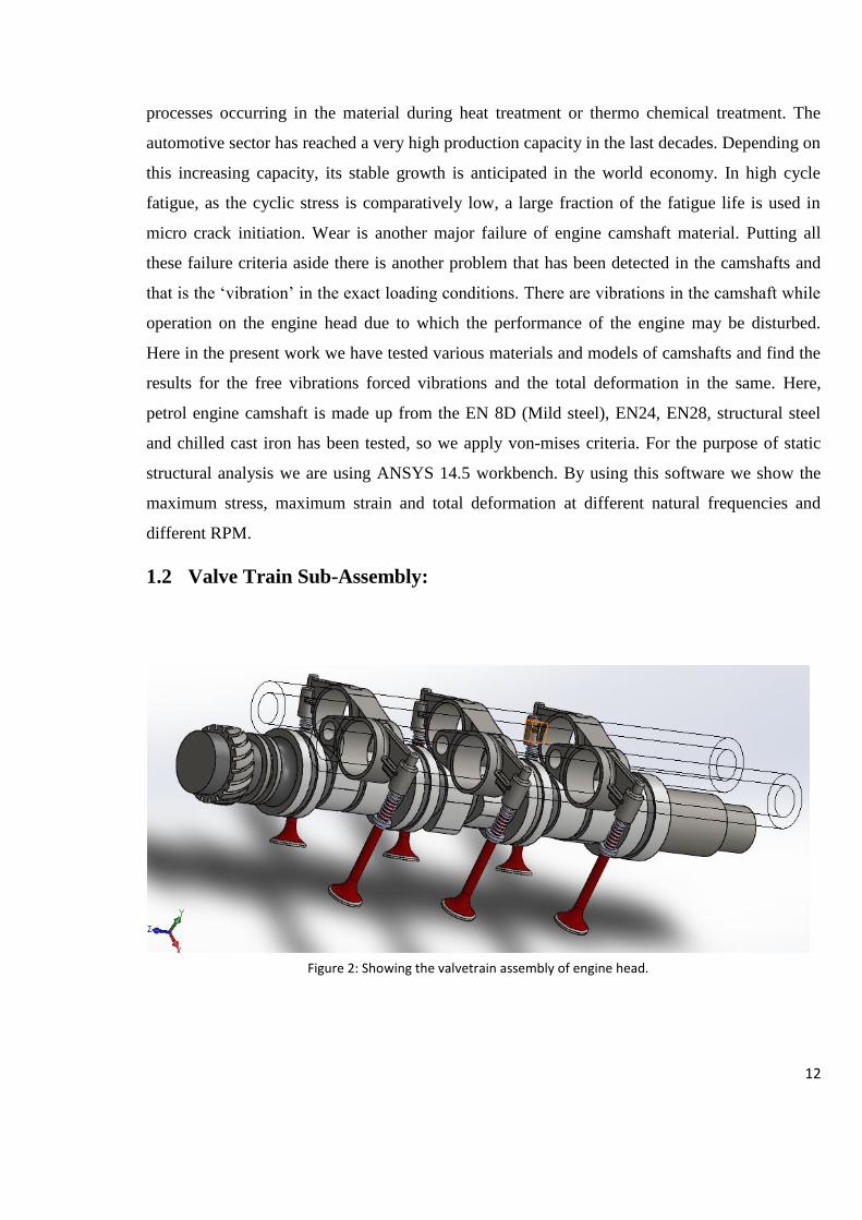
1.2 Valve Train Sub-Assembly:
Figure 2: Showing the valvetrain assembly of engine head.

13
The valve train in an engine is used to regulate the valve opening and closing at the inlet and
exhaust stork of the crank shaft (piston TDC and BDC). Mainly the timing of the engine is
regulated by the valve train assembly so that the firing order would be in such a way that there
will be only one piston firing at a time. The lobes were rotated in such a way so that the 2nd,
3rd, and 4th lobes were 90°, 270° and 180° from the 1st lob respectively. This angular
difference from each cam assembly to the next causes each piston to fire at a time when no other
piston is firing. SOHC is called Single Overhead Cam Assembly i.e. the cam is on the head of
the engine. And is single operated. To allow the appropriate motion, the cam-follower
mechanisms was defined for each cam and rocker combinations.
Key Words: Camshaft, Failure analysis, Stress analysis, Dynamic models, SOHC, Valve train
Kinematic pair, lobes.
14
CHAPTER -2
2 REVIEW OF LITERATURE
In this portion the different views of different authors has been discussed on the mechanism,
design and optimization of a camshaft. Camshaft is a main part of the engine. It acts like a brain
of the engine as it regulates the opening and closing of the intake and the exhaust valve. It is
situated on the top head of the engine where it is covered by a cover called tappet cover. It is
generally being correlated by the timing of the engine as it also regulates the timing of the
valves i.e.- it determines for how long the exhaust valve should closed and for how long the
intake valve should be opened for a intake stroke and same for the power and the exhaust stroke.
Therefore the camshaft must be optimized and designed in such a manner so that there would be
no harm to the engine performance and to the vehicle as well. Now a days it is a common
problem for a vehicle i.e. the failure of the cam shaft, or the camshaft heating and fracture of
camshaft. So to prevent these problem I am going to discuss some of the main research and
experiment done on the camshaft design till date.
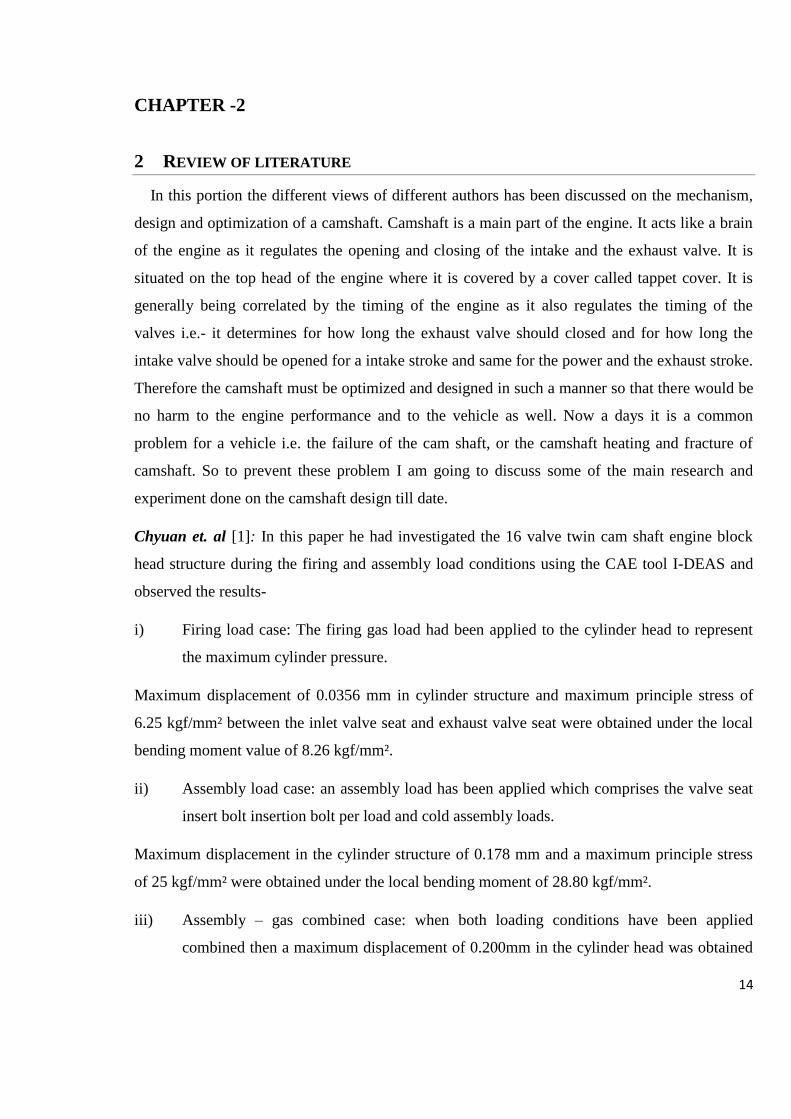
Chyuan et. al [1]: In this paper he had investigated the 16 valve twin cam shaft engine block
head structure during the firing and assembly load conditions using the CAE tool I-DEAS and
observed the results-
i) Firing load case: The firing gas load had been applied to the cylinder head to represent
the maximum cylinder pressure.
Maximum displacement of 0.0356 mm in cylinder structure and maximum principle stress of
6.25 kgf/mm² between the inlet valve seat and exhaust valve seat were obtained under the local
bending moment value of 8.26 kgf/mm².
ii) Assembly load case: an assembly load has been applied which comprises the valve seat
insert bolt insertion bolt per load and cold assembly loads.
Maximum displacement in the cylinder structure of 0.178 mm and a maximum principle stress
of 25 kgf/mm² were obtained under the local bending moment of 28.80 kgf/mm².
iii) Assembly – gas combined case: when both loading conditions have been applied
combined then a maximum displacement of 0.200mm in the cylinder head was obtained

15
and a maximum principle of 25 kgf/ mm² were obtained under the local bending moment
of 30.40 Kgf/mm².
Jean W. Zu etal [2]: In this paper he had optimized and designed a new cam drive engine
model, first he had design the typical cam profile design by analysing the unique cam
mechanism he had also discussed the contact stress, radius of curvature, and pressure angle as
the constraints by considering the output torque as main objective of the design. Then he had
compared the results and optimized it using the GA [3] (genetic algorithm) method for both
conventional engine and the new cam drive engine. General polynomial spline [4] were used to
represent the profiles of both intake cam and exhaust cam (stroke) which increased the mean
torque by 18%. A modified spline equation called ‘B-splines’ [5] were used to increase the
performance for investigation and it is improved by 24%.Moreover, the output torque generated
by the best profiles increased by 28% compared to that generated by the initial profiles. At the
same time, the smoothness of the best profiles was also comparable to that for the initial
profiles.
Johnson et al [3]: In this article Johnson had presented the proper approach to designing an
earn-follower system, and in the process also present some less than proper designs as examples
of the problems which are faced by most of the inexperienced earn designers. He also had
discussed the cam terminologies, cam motions and constraints. Some laws were also employed
such as ‘The cam function must be continuous through the first and second derivatives of
displacement across the entire interval (360 degrees)’. ‘The jerk function must be finite across
the entire interval (360 degrees)’. In any but the simplest of cams, the cam motion program
cannot be defined by a single mathematical expression, but rather must be defined by several
separate functions, each of which defines the follower behaviour over one segment, or piece, of
the cam. Expressions are sometimes called piecewise functions.
Dhavale et al [4]: In his work he had discussed the stress analysis and the fracture analysis of
the cam shaft also depicted the importance of the cam shaft in an engine. Derived some relations
and results by taking the specific material for the camshaft manufacturing also analysed the
results using the finite element methods and software. He also prepared a dynamic model for
FEA analysis. He had used the iron alloy with specific weight ratios of different elements as
Carbon, Silicon, Manganese, Molybdenum, Nickel, Aluminium Copper, Titanium, Magnesium,
Sulphur, Phosphorus, 3.42%, 2.33%, 0.296%, 0.010%, 0.038%, 0.010%, 0.518%, 0.028%,
16
0.026%, 0.009%, 0% respectively and remaining Ferrous was taken alone. The stress analysis of
the camshaft was carried out for the determination of the stress concentration level at the
fracture region by the finite element method. The failure is occurred as a sudden fracture at very
close to journal location, where there was a stress concentration. The main reason of the fracture
was determined as a casting defect. The failure was found to be related to production of the
camshaft material.
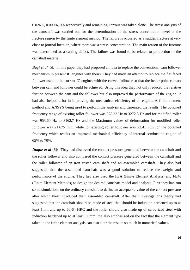
Bagi et al [5]: In this paper they had proposed an idea to replace the conventional cam follower
mechanism in present IC engines with theirs. They had made an attempt to replace the flat faced
follower used in the current IC engines with the curved follower so that the better point contact
between cam and follower could be achieved. Using this idea they not only reduced the relative
friction between the cam and the follower but also improved the performance of the engine. It
had also helped a lot in improving the mechanical efficiency of an engine. A finite element
method and ANSYS being used to perform the analysis and generated the results. The obtained
frequency range of existing roller follower was 828.32 Hz to 3272.8 Hz and for modified roller
was 953.60 Hz to 3162.7 Hz and the Maximum values of deformation for modified roller
follower was 21.675 mm, while for existing roller follower was 23.41 mm for the obtained
frequency which results an improved mechanical efficiency of internal combustion engine of
65% to 70%.
Duque et al [6]: They had discussed the contact pressure generated between the camshaft and
the roller follower and also compared the contact pressure generated between the camshaft and
the roller follower of an iron casted cam shaft and an assembled camshaft. They also had
suggested that the assembled camshaft was a good solution to reduce the weight and
performance of the engine. They had also used the FEA (Finite Element Analysis) and FEM
(Finite Element Methods) to design the desired camshaft model and analysis. First they had run
some simulations on the ordinary camshaft to define an acceptable value of the contact pressure
after which they introduced their assembled camshaft. After their investigations theory had
suggested that the camshaft should be made of steel that should be induction hardened up to at
least 1mm and up to 60-64 HRC and the roller should also made up of carburized steel with
induction hardened up to at least .08mm. the also emphasized on the fact that the element type
taken in the finite element analysis can also alter the results so much in numerical values.
17
Kumar et al [7]: In this paper they had also remodelled designed and analysed the cam shaft in
FEM. They had discussed the techniques and methods to make the camshaft robust and versatile
to all the possible loading conditions. They had also analysed the dynamic behaviour of the cam
shaft during load conditions to calculate the exact load value for the camshaft operation. For the
operation and force values they had employed the finite element method. From these operations
they found maximum design strength is 240.6 N/mm2 from the material property given as
Young's modulus 210000-210000 MPa, Tensile strength 600 - 800 MPa, Elongation 16 - 16 %,
Yield strength 340 – 400 MPa the ultimate tensile strength of the material is 720 N/mm2, then
the factor of safety becomes within that safety limits.
Escobar et al [8]: In their work they had employed a non-destructive testing [12] method for
three 2.3L cam shafts in an engine simulator for an equivalent of 100,000 miles. They had
employed various methods to draw the results such as optical microscopy, acoustic microscopy
and profilometry [13]. But there were no evidence of any tribological effect due to the sliding
friction of the follower. Generally they had investigated the surface roughness cracks, crack
depth of at a general camshaft lobes. They had found the cracks of 300µm in length due to
grinding of the lobes during fractography [14] testing. X-ray residual stress test [15] shown the
evidence of residual stress relaxation. Moreover there were two type of cracks mainly found on
the surface of the camshaft lobes straight and pitted. Straight cracks were nucleated due to the
grinding operations and pitted cracks were due to impact and cyclic load generated by the
follower during the testing. So they had suggested to re-hardening of the lobes and the follower
to maintain the exact working conditions.
Singhose et al [9]: They had investigate the cause of unwanted vibration and force during the
cam operation. Because unwanted vibration in cam-follower systems causes increased operating
forces and costs. They also investigated the importance of the shape function of a cam profile.
They had investigated the function using real-time command modification method. They also
had manufactured the experimental apparatus for results and demonstration. A simple input
shaping procedure was developed to modify cam profiles so that they do not excite a known
vibration frequency. The final shaped cam profile results in no residual vibration of the follower.
This was only applicable for the single speed cam but they also developed the extension for the
variable speed operations.

18
Zhang et al [10]: In this paper they had optimized the camshaft grinding process parameters
using GA (Genetic algorithm) and ANN (artificial neutral network) methods. GA is used to
improve the accuracy and speed based on the ANN model. After the experiment they collected
the samples that were designed by uniform design, six samples were collected from previous
machining process to test the network. The errors to test the network by six testing data had a
uniform distribution pattern about zero with a mean value and standard deviation of −0.05% and
7.46%, respectively. The result shows that 85.42% of the predicted values have the percentage
error ranging between ±10percent. Hence they had concluded that the GA and ANN method can
be used for the optimization of the grinding parameters of a camshaft.
Wanjari et al [11]: In this paper they had discussed the various results on camshaft at different
speed and loading conditions. They had also discussed the failure reasons and the factors
affecting the performance of a camshaft, they have tried to change the material of the camshaft
so that the thermal flux and the shear stresses may be balance in some satisfactory regions. They
has found that the values of shear stress in grey cast iron is minimum. And the value of total
deformation is low for forged steel. The maximum values of loads 3500N and 5000N they have
obtained maximum value of shear stress and total deformation. These value of loads are
obtained at initial / starting stage of the vehicle when it was running at 1650 to 1950 RPM. So
they had recommended that, the vehicle should cross this range of engine speed as early as
possible and the grey cast iron is the best material for manufacturing of camshaft.
Li Ping et al [12]: They had performed an experiment with the camshaft made of chilled cast
iron in this paper. They had installed the homemade casted chilled cast iron camshaft in a home-
made Fukang car. The fracture had occurred only after running over a distance of 6,200 km.
They had also discussed the cause of failure at microstructure level. The main reason for the
fracture failure of the camshaft is that a too strong chilled trend existed in the transition region.
The microstructure of fracture zone is Ledeburite, and its hardness is also beyond the range of
the standard.
S.G.Thorat et al [13] : they had done the camshaft analysis in the ANSYS software they have
also calculated the loading conditions of the camshaft on the bases of the engine specifications
they also have used the formulae for the total deformation in the camshaft for the FE analysis
they have used ANSYS software for a load of 1134 N they were getting a deflection of
.00059mm in the camshaft when they have used some specific material. They have compared
19
the results those were calculated manually with the analytical those were calculated using
software.
Kolchin-Demidov [14] : the book design of automotive engine is the key to calculate the exact
loading conditions for the camshaft in this book they have provided the equations and the
loading conditions for each components in the engine they have also considered the engine
specifications in the loading and provide the exact equation for the solution.
Mohd H. Othman [15] : in his research he had analyse the frequency and the vibration of the
cam and follower mechanism he had provide the method and the exact boundary conditions that
may also applied to the system that is using the cam and follower mechanism. He had analyse
the vibrations of the DYNACAM 1998 and also analyse the effect of the impact force on the
vibrations of cam and follower.
Kothari et al [16] : they have calculated the deformation in the cam using the different material
they had calculated the total deformation in the cam during the loading conditions using the
ANSYS 12.1 software. They have calculated the total hydraulic pressure and the load on the
cam due to the cylinder and calculated the deformation in cam they have calculated the total
deformation in the exhaust cam inlet cam and the fuel cam simultaneously.
2.1 OUTCOMES
2.1.1 Summary:
From this literature review we now know that there are various fields on which we can explore
the research i.e. – camshaft, they have done an anonymous work related to the fields. The work
of each and every author is very informative and helpful but there are some fields where no one
has worked yet. Some of the researchers had work in the fracture analysis of the camshaft they
have calculated the maximum load that a camshaft can bare they have used different materials
too such as chilled cast iron and stainless steels but they haven’t got the desired results there was
always a some deficiency elated to the life of the camshaft. Then researchers have done some
tribological analysis on the camshaft they have changed the behaviour and the nature of contact
between the camshaft and follower they have replaced the flat follower to the round one, which
improved the span and the lift of follower now camshaft was optimised and the wear and friction
20
between cam and follower was reduced. Afterwards researchers have also developed an engine
without camshaft which was a concept only but they have replaced the camshaft mechanism
with some curved circular rotatory engine that was having the same timing diagram as the
camshaft engine. In present scenario the vehicles are not using these camshafts they are using
the electronic injection system which allows the user to set the timing electronically for the
vehicle. But in the high performance vehicles they are still using the camshaft as the main part
of engine because camshaft provides the reliability and durability with the mechanical point of
view. In the present work the main focus of study is the camshaft and its vibrations with total
deformation and calculation of the exact loading conditions of a camshaft.
2.1.1.1 Gaps in research:
The researchers have done a lot of work related to the camshaft they have calculated the
maximum loads and the strength of camshaft, materials those can be used for the manufacturing
of the camshaft. They have also calculated the lifespan of the component according to the
researchers that we have gone through and almost we have gone through the all, they have done
the work related to the material and the wear, smoothness, replacement and total change in
mechanism related to camshaft. According to all the research and literature that is reviewed
there is nothing done for the vibration control of the camshaft so there is a gap between these
researches that is provided by the ‘Mahesh R. Mali1, Prabhakar D. Maskar, Shravan H.
Gawande, Jay S. Bagi’ they have calculated the natural frequencies of the roller follower
provided with the operating speed and pressure in Design Optimization of Cam & Follower
Mechanism of an Internal Combustion Engine for Improving the Engine Efficiency, Journal of
Modern Mechanical Engineering, vol. 2 / March 2012 [5]. They have purposed that if we are
using the roller follower instead of the flat follower the natural frequency of the cam and
follower can be reduced. So in the following work we have focused the research related to the
vibration analysis of the camshafts of different materials those are available in the market and
can be use as the raw material for the component.
We here are going to calculate and optimize the vibration causes and frequencies of camshaft
with the total deformation and the results are then compared with each other using different
materials.
21
CHAPTER-3
3 OBJECTIVE OF STUDY (PROBLEM FORMULATION)
To calculate the actual loading conditions for the camshaft, during operation.
Vibration and FEA analysis of camshaft using ANSYS software.
We will be preparing a full SI engine valve train mechanism in the modelling softwares and
analysing the vibration causes after calculating the causes and frequencies of the vibration
we will be optimizing the vibrations by changing the material and try to find the most
suitable material for camshaft manufacturing.
Increase the performance of an engine
With the vibration control and optimization in the camshaft we can improve the engine
performance, as vibration causes very large energy loss during the engine operation
3.1 SCOPE OF STUDY
With the help of this work that we are going to do here one can improve the performance,
efficiency and life of any SI engine which uses the camshafts. This work may be helpful to
calculate the exact loading and working conditions of camshaft in an engine. The main scope of
this study is to calculate the total vibration in the camshaft and the various deformation mode
shapes, those are calculated at different frequencies.
This research is also helpful in the field of vibration and friction analysis of cam and follower
mechanism.
3.2 EXPECTED OUTCOMES
The material tested for the fabrication and design testing of the cam shaft i.e EN8 D/ EN24 steel
is the suitable material for the camshaft manufacturing it has very effective torsional strength
and having the properties that are suitable for the operation.
The natural frequencies are optimised and the engine performance is increased.
22
CHAPTER-4
4 RESEARCH METHODOLOGY
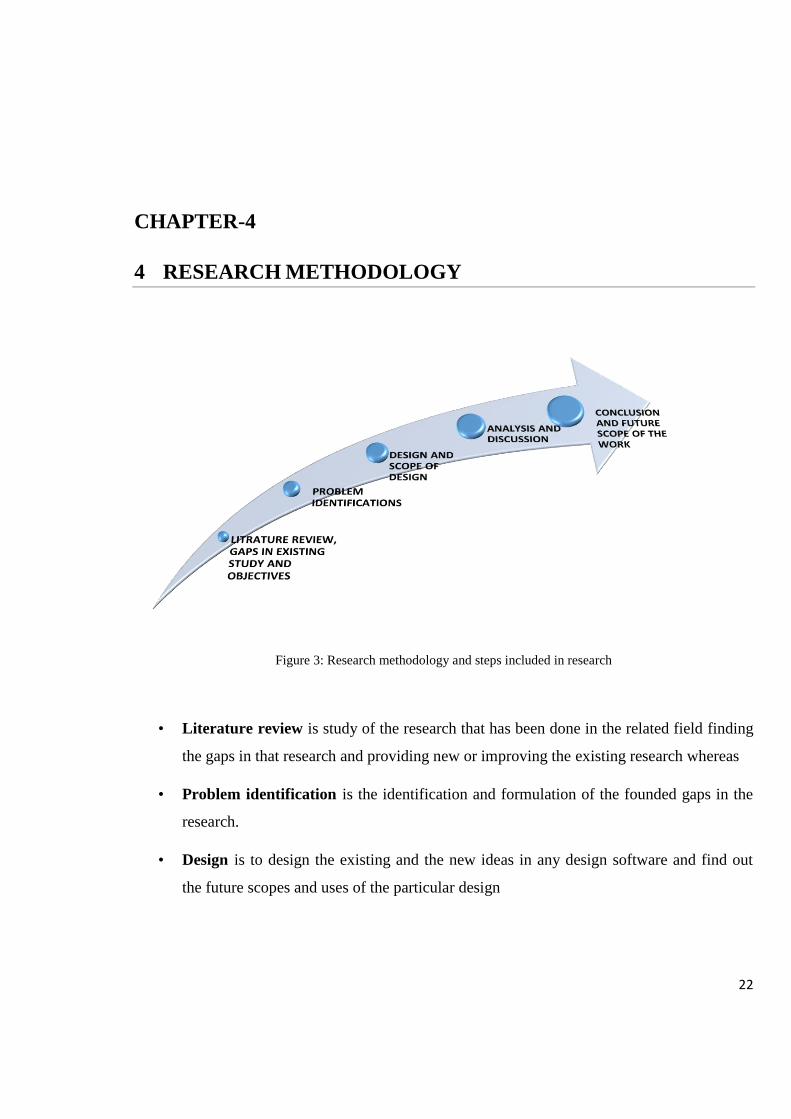
Figure 3: Research methodology and steps included in research
• Literature review is study of the research that has been done in the related field finding
the gaps in that research and providing new or improving the existing research whereas
• Problem identification is the identification and formulation of the founded gaps in the
research.
• Design is to design the existing and the new ideas in any design software and find out
the future scopes and uses of the particular design
23
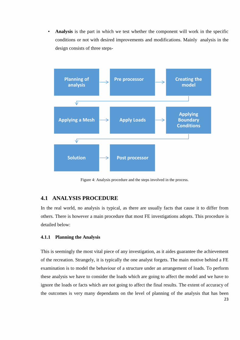
• Analysis is the part in which we test whether the component will work in the specific
conditions or not with desired improvements and modifications. Mainly analysis in the
design consists of three steps-
Figure 4: Analysis procedure and the steps involved in the process.
4.1 ANALYSIS PROCEDURE
In the real world, no analysis is typical, as there are usually facts that cause it to differ from
others. There is however a main procedure that most FE investigations adopts. This procedure is
detailed below:
4.1.1 Planning the Analysis
This is seemingly the most vital piece of any investigation, as it aides guarantee the achievement
of the recreation. Strangely, it is typically the one analyst forgets. The main motive behind a FE
examination is to model the behaviour of a structure under an arrangement of loads. To perform
these analysis we have to consider the loads which are going to affect the model and we have to
ignore the loads or facts which are not going to affect the final results. The extent of accuracy of
the outcomes is very many dependants on the level of planning of the analysis that has been
Planning of analysis
Pre processor Creating the model
Applying a Mesh Apply LoadsApplying Boundary Conditions
Solution Post processor
24
carried out. Answers of too many questions is needed to be found. Planning of the analysis deals
with the extant of the results accuracy because better would be the planning more accurate will
be the results.
4.1.2 Pre-Processor
Pre-processor in the general FE model analysis includes the name of the file, problem. Providing
a name to a file is considered as the optional but it is very useful when you are dealing with the
various analysis on the same project, it also provides the difference between the various
iterations of the processes those are applied on the same base model. There are various type of
analysis those can be used, e.g. structural, fluid, thermal or electromagnetic, etc. (sometimes this
can only be done by selecting a particular element type).
4.1.3 Creating the model
The model is first drawn in the 2d sketch space in the appropriate units (M, mm, in, cm, ft. etc.)
The model then is converted into the 3D space using the design softwares like Pro-E,
Solidworks etc. then it can be imported to the another CAD drafting package by the neutral file
formats like IGES, STEP, ACIS, Parasolid txt. DXF etc. if a model is created in the software
with unit in mm for example then after importing the model the units of the model in the
software should remain the same if it is not so the results may go out of scale and will not match
the final expectations. This is the common mistake that is done by most of the analysers and
don’t even points out. Defining the element type, this may be 1D, 2D or 3Dand specific to the
analysis type being carried out (you need thermal elements to do thermal analyses).
4.1.4 Applying a Mesh
There are three main type of meshing –
Structured meshing
It is a mesh type which is characterized by its regular shape arrays of the elements which are
connected to each other. They can be 2 dimensional or 3 dimensional elements. This restricts
the element choices to quadrilaterals in 2 Dimensional or hexahedra in 3 Dimensional elements.

25
The regularity of the connectivity allows us to conserve space since neighbourhood relationships
are defined by the storage arrangement.
Unstructured meshing
It is a mesh type which is characterized by its irregular shape arrays of the elements which are
connected to each other. This allows for any possible element that a solver might be able to use.
Compared to structured meshes, the storage requirements for an unstructured mesh can be
substantially larger since the neighbourhood connectivity must be explicitly stored.
Hybrid meshing
In hybrid meshing the mesher includes the mixture of the element type it contains the structured
and unstructured portion of meshing. This type of meshing requires the knowledge of both type
of meshing in previous. Therefore it is also called the mixed type of meshing because it contains
the element of the structured meshing type and the unstructured meshing in an array
(presumably stored in an unstructured fashion).
Meshing is the process to use to divide a large model into the small discreet elements which
have a defined shape and size that can be controlled by the user. There are several geometry
having irregular shapes and sizes to calculate total deformation in such elements or to find the
stress generated after load or to calculate various other results, it is very tedious task. To make
all these part easy to calculate meshing is used it divides such geometry into small elements for
which we have definite formulae and functions to calculate these results. Then all these results
are being integrated to get the total solution for the geometry. One can control the size of the
elements to get the fine meshing. The finer the mesh, the better are the results, but it also takes
longer time to calculate the results. Therefore, we made a compromization between the accuracy
and the solution speed usually. The mesh may be created manually, or generated automatically
like the one that is shown below. When we create the meshing manually we have seen that the
element size on the ends of the geometry are smaller in comparison to the other elements this is
called the refinement of mesh size. Manual meshing is a long & tedious process for models with
large degree of geometric complication, but with the tool like automatic mesh generator
relevance and sizing of elements it becomes easier. Automatic meshing has limitations as
regards mesh quality & solution accuracy because Automatic brick element (hex) mashers are
limited in function, but these are steadily improving. Any mesh is usually applied to the model
26
by simply selecting the mesh command on the pre-processor list of the GUI expansion, friction,
thermal conductivity, damping effect, specific heat etc.) Will have to be defined. In addition
element properties may need to be set. If 2D elements are being used, the thickness property is
required. Special elements require properties specific to the element types like mass, contact,
spring, gap, coupling, damper etc. to be defined for their use.
4.1.5 Apply Loads
Some sort of load is generally connected to the examination model. The stacking may be as a
point load, a weight or a dislodging in an anxiety (relocation) investigation, a temperature or a
heat flux in a thermal examination & a liquid weight or speed in a fluid examination. The loads
may be connected to a point, an edge, a surface or an even a complete body. The loads ought to
be in the same units as the model geometry & material properties indicated. In the instances of
modular (vibration) & clasping examinations, a load does not need to be determined for the
investigation to run.
4.1.6 Applying Boundary Conditions
On the off chance that you apply a load to the model, then so as to stop it quickening endlessly
through the PC's virtual ether (scientifically known as a zero turn), no less than one requirement
or limit condition must be connected. Auxiliary limit conditions are more often than not as zero
relocations, thermal BCs (boundary conditions) are generally indicated temperatures, fluid BCs
are typically determined weights. A limit condition may be determined to act in all headings (x,
y, z), or in specific bearings just. They can be put on hubs, key focuses, and zones or on lines.
BC's on lines can be as symmetric or hostile to symmetric sort limit conditions, one permitting
in plane pivots and out of plane interpretations, the other permitting in plane interpretations and
out of plane turns for a given line. The uses of right limit conditions are discriminating to the
precise arrangement of the outline issue. No less than one limit condition must be connected to
each model, even modular & clasping examinations with no loads connected. See the 'Propelled
Boundary Conditions' segment for clarifications on more propelled limit condition sorts.
27
4.1.7 Solution
Thankfully, this part is completely programmed. The FE solver can be consistently isolated into
three primary parts, the pre-processor, the mathematical engine, & the post-processor. The pre-
processor peruses in the model made by the pre-processor and defines the scientific
representation of the model. All parameters characterized in the pre-processing stage are utilized
to do this, so in the event that you forgot something, odds are the pre-processor will gripe &
cross out the call to the mathematical engine. On the off chance that the model is amend the
solver continues to shape the component solidness network for the issue & calls the
mathematical engine which computes the outcome (dislodging, temperatures, weights, and so
on.) The outcomes are come back to the solver & the post-solver is utilized to ascertain strains,
hassles, heat fluxes, speeds, and so forth for every hub inside the part or continuum. Every one
of these outcomes are sent to an outcome record, which may be perused by the post-processor.
4.1.8 Post-Processor
Thankfully, this part is completely programmed. The FE solver can be consistently isolated into
three primary parts, the presolver, the scientific motor, & the post-solver. The presolver peruses
in the model made by the pre-processor and defines the scientific representation of the model.
All parameters characterized in the pre-processing stage are utilized to do this, so in the event
that you forgot something, odds are the presolver will gripe & cross out the call to the scientific
motor. On the off chance that the model is amend the solver continues to shape the component
solidness network for the issue & calls the scientific motor which computes the outcome
(dislodging, temperatures, weights, and so on.) The outcomes are come back to the solver & the
post-solver is utilized to ascertain strains, hassles, heat fluxes, speeds, and so forth for every hub
inside the part or continuum. Every one of these outcomes are sent to an outcome record, which
may be perused by the post-processor.
4.2 Material used for the analysis:
4.2.1 Cast iron:
This is a good option for a high volume production. Chilled cast iron camshaft have greater
value of wear resistance because the lobes of the cam have been chilled, generally makes them

28
harder. Before chilled iron casting some materials also added to the cast iron to make the
material more suitable for the application.
4.2.2 Structural steel:
Whenever a high performance camshaft is required it is being made by billet steel. This is very
low volume production process and very time consuming. The method is very expensive but the
finishing that is obtained is far better than other process. Therefore we are going to use three
different material
29
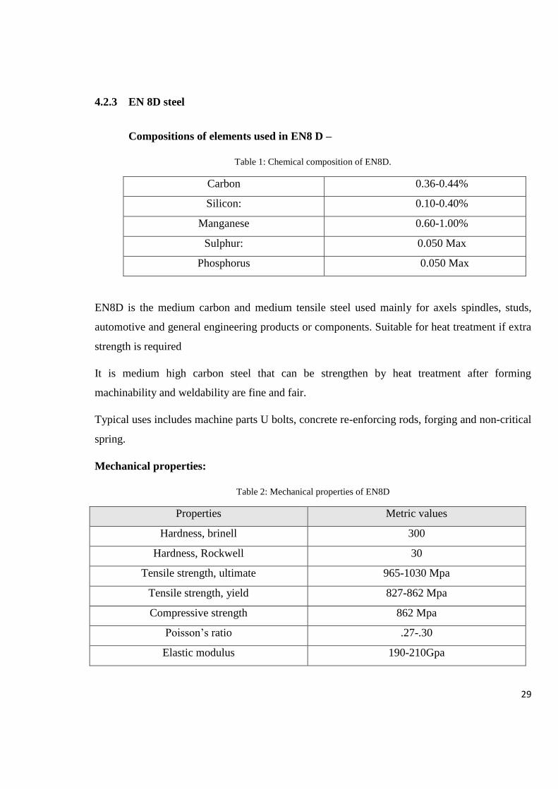
4.2.3 EN 8D steel
Compositions of elements used in EN8 D –
Table 1: Chemical composition of EN8D.
Carbon 0.36-0.44%
Silicon: 0.10-0.40%
Manganese 0.60-1.00%
Sulphur: 0.050 Max
Phosphorus 0.050 Max
EN8D is the medium carbon and medium tensile steel used mainly for axels spindles, studs,
automotive and general engineering products or components. Suitable for heat treatment if extra
strength is required
It is medium high carbon steel that can be strengthen by heat treatment after forming
machinability and weldability are fine and fair.
Typical uses includes machine parts U bolts, concrete re-enforcing rods, forging and non-critical
spring.
Mechanical properties:
Table 2: Mechanical properties of EN8D
Properties Metric values
Hardness, brinell 300
Hardness, Rockwell 30
Tensile strength, ultimate 965-1030 Mpa
Tensile strength, yield 827-862 Mpa
Compressive strength 862 Mpa
Poisson’s ratio .27-.30
Elastic modulus 190-210Gpa

30
4.2.4 EN 28 steel:
Composition of elements used in EN 28-
Table 3: Chemical composition of EN28
Carbon 0.25%
Silicon: 0.15%
Manganese 0.52%,
Sulphur: 0.024%,
Phosphorus 0.010%
Chromium 1.14%
Molybdenum 0.65%
Vanadium 0.16%
Nickel 3.33%
4.2.5 EN 24 steel:
Composition of elements used in EN 24 –
Table 4: Chemical composition of EN24
Carbon .36/.44%
Silicon: .10/.35%
Manganese .45/.70%,
Sulphur: .040%,
Phosphorus .035%
Nickel 1.30/1.70%
Chromium 1.00/1.40 %
Molybdenum .20/.30%
EN24 is a very popular of through hardening alloy steel, it is most suitable for the
manufacturing of the parts such as heavy duty axles and shafts, gears, bolts and studs. EN24 can
be further be surface hardened typically to 58 to 60 HRC by induction or nitride processes,
producing components which enhanced wear resistance. EN24 is capable of retaining good
impact value at low temperatures.

31
For the model design purpose here we have used the Solidworks software which is a very
reputed 3D CAD design software the analysis and simulation can also be done on the same
software but for specific results and accuracy we have used ANSYS software
4.3 WORK PLAN WITH TIME
Month
Activity
Sep. Oct Nov Dec Jan Feb Mar.
Objective
Literature
Review
Design
Experimental
design/analysis
Results and
discussion
Report writing
Table 5: work plane with estimated time

32
CHAPTER -5
5 RESULTS AND DISCUSSION
5.1 TOTAL DEFORMATION IN CAMSHAFT OF DIFFERENT MATERIALS
Camshaft is the rotating component that bears the critical loads. The calculation of the exact
load is very important for the part than the other rotating parts of the engine. This paper provides
the guidelines to deal with such situations hence the objective is to design the camshaft
analytically and analyse the frequency and vibrations in modal analysis and the total
deformation statically.
Figure 5: showing the CAD model of camshaft
Units used:
Unit System: Metric (mm, kg, N, s, mV, mA) Degrees rad/s Celsius
Angle: Degrees

33
5.1.1 Loading conditions:
5.1.1.1 Calculation of loads on camshaft:
Engine specifications:
Table 6: Engine specification for loading
Power 27.6KW at 5000 RPM
Torque 59Nm at 2500 RPM
Cylinder volume 796CC
Stroke 72mm
Bore 66.5mm
C.R (compression ratio) 9:2
Inlet valve opens 10° BTDC
Firing order 1-3-2
An engine of 800 cc was tested and the values those are given in the above table was obtained it
generated 27.6 KW of power when it was at full throttle i.e at 5000rpm. The total torque on the
shaft was 59Nm when crank was rotating at a speed of 2500 rpm, bore diameter measured was
66.5mm and the firing order given was 1-3-2 or 1-2-3.
Camshaft specifications:
Table 7: Camshaft specifications.
Cam width 18mm
Camshaft diameter 28.6mm
Journal diameter 50mm
Cam height 41.3mm
Total lift of cam 7.65mm
The camshaft that was being tested was having a base diameter of 28.66mm and having 6 cams
on it with 18mm width each. The journal bearing those were on the camshaft were of 50mm
34
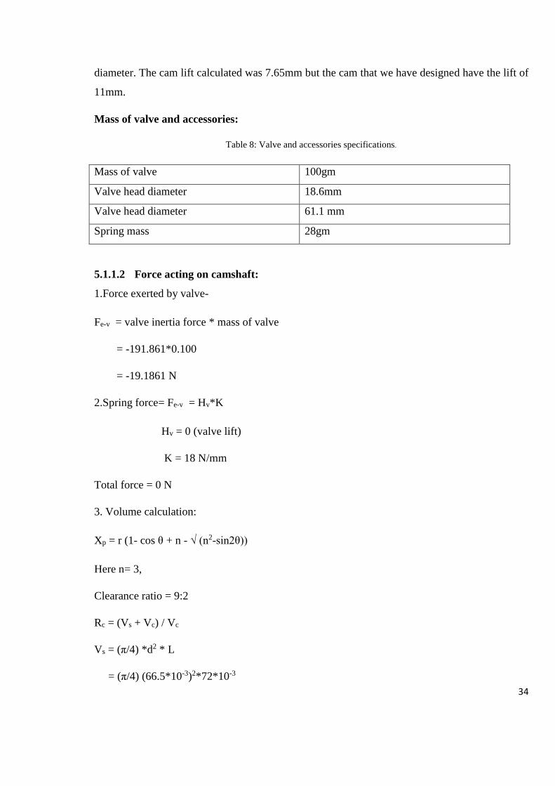
diameter. The cam lift calculated was 7.65mm but the cam that we have designed have the lift of
11mm.
Mass of valve and accessories:
Table 8: Valve and accessories specifications.
Mass of valve 100gm
Valve head diameter 18.6mm
Valve head diameter 61.1 mm
Spring mass 28gm
5.1.1.2 Force acting on camshaft:
1.Force exerted by valve-
Fe-v = valve inertia force * mass of valve
= -191.861*0.100
= -19.1861 N
2.Spring force= Fe-v = Hv*K
Hv = 0 (valve lift)
K = 18 N/mm
Total force = 0 N
3. Volume calculation:
Xp = r (1- cos θ + n - √ (n2-sin2θ))
Here n= 3,
Clearance ratio = 9:2
Rc = (Vs + Vc) / Vc
Vs = (π/4) *d2 * L
= (π/4) (66.5*10-3)2*72*10-3

35
Vs = 2.49945*10-4m3
Vc = Vs + Vc / Rc
Vc= 6.857*10-5 m3
Total volume:
Vt = Vs + Vc
= 3.18515*10-4m3
4. Gas force:
Fg =Valve head area* gas pressure
= (π/4) * dp * P΄
= 271.5*10-6m2*.6065 Mpa
= 164.52 N
Force on camshaft:
= 164.52*(rocker arm ratio)
= 164.52*(39.3/36.3)
=178.11 N
5. Deflection in shaft-
y = 0.8 * Fmax * a2* b2 / [E * L*(dc4 –δc4)]………………………………………... [1]
y=.0024mm
6.Bending stress:
σb = [Mbmax / Wb]= [Fmax* b* a * 32] / [π * dc3 * (1-(δc4 / dc4)) * L]……. [1]
σb= 1.399Mpa

36
5.1.2 MODEL
5.1.2.1 Geometry: Table 9: Details of the geometry used for FE analysis
Object Name Camshaft
State Fully Defined
Bounding Box
Length X 357. mm
Length Y 44.5 mm
Length Z 44.5 mm
Properties
Volume 3.3025e+005 mm³
Mass 2.5925e-003 kg
Statistics
Nodes 28701
Elements 17207
Figure 6 : Showing the meshed wireframe and deformed wireframe of camshaft.
5.1.3 For EN8D:
EN8 D is the medium carbon and medium tensile steel used mainly for axels spindles, studs,
automotive and general engineering products or components. Suitable for heat treatment if extra
strength is required
It is medium high carbon steel that can be strengthen by heat treatment after forming
machinability and weld ability are fine and fair.
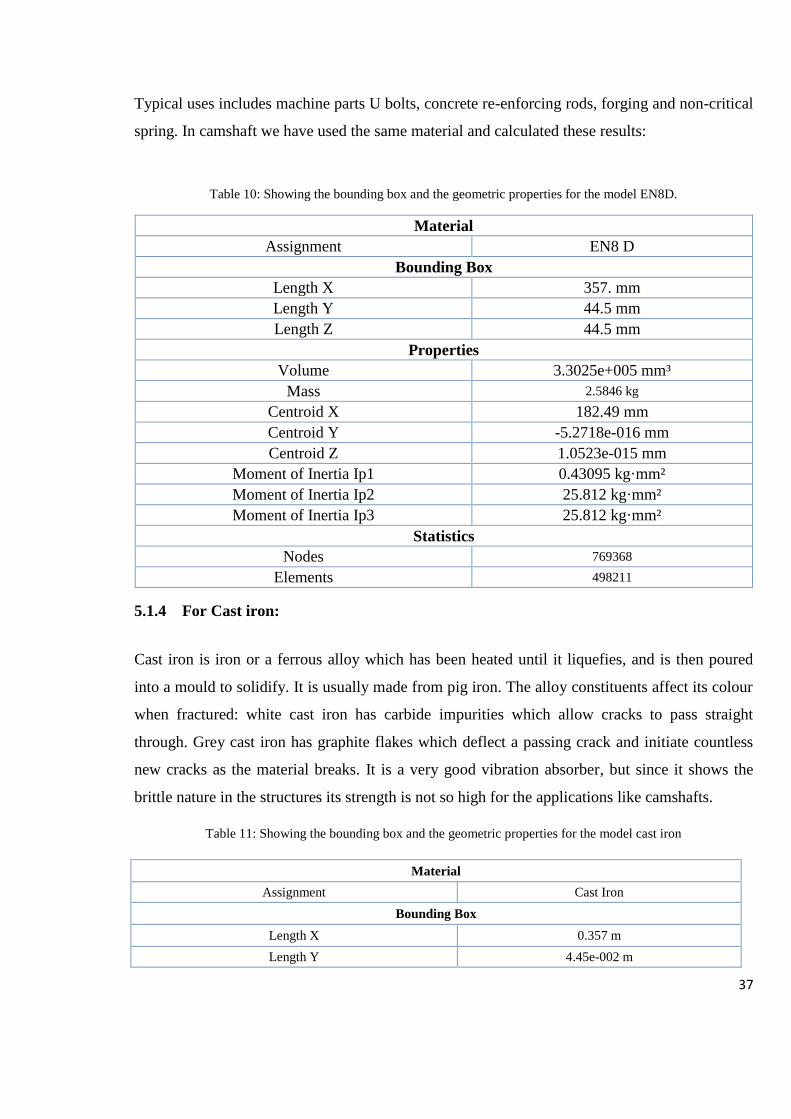
37
Typical uses includes machine parts U bolts, concrete re-enforcing rods, forging and non-critical
spring. In camshaft we have used the same material and calculated these results:
Table 10: Showing the bounding box and the geometric properties for the model EN8D.
Material
Assignment EN8 D
Bounding Box
Length X 357. mm
Length Y 44.5 mm
Length Z 44.5 mm
Properties
Volume 3.3025e+005 mm³
Mass 2.5846 kg
Centroid X 182.49 mm
Centroid Y -5.2718e-016 mm
Centroid Z 1.0523e-015 mm
Moment of Inertia Ip1 0.43095 kg·mm²
Moment of Inertia Ip2 25.812 kg·mm²
Moment of Inertia Ip3 25.812 kg·mm²
Statistics
Nodes 769368
Elements 498211
5.1.4 For Cast iron:
Cast iron is iron or a ferrous alloy which has been heated until it liquefies, and is then poured
into a mould to solidify. It is usually made from pig iron. The alloy constituents affect its colour
when fractured: white cast iron has carbide impurities which allow cracks to pass straight
through. Grey cast iron has graphite flakes which deflect a passing crack and initiate countless
new cracks as the material breaks. It is a very good vibration absorber, but since it shows the
brittle nature in the structures its strength is not so high for the applications like camshafts.
Table 11: Showing the bounding box and the geometric properties for the model cast iron
Material
Assignment Cast Iron
Bounding Box
Length X 0.357 m
Length Y 4.45e-002 m
38
Length Z 4.45e-002 m
Properties
Volume 3.2925e-004 m³
Mass 2.3706 kg
Centroid X 0.18204 m
Centroid Y -1.551e-007 m
Centroid Z -3.5636e-008 m
Moment of Inertia Ip1 3.9288e-004 kg·m²
Moment of Inertia Ip2 2.3502e-002 kg·m²
Moment of Inertia Ip3 2.3502e-002 kg·m²
Statistics
Nodes 769368
Elements 498211
.
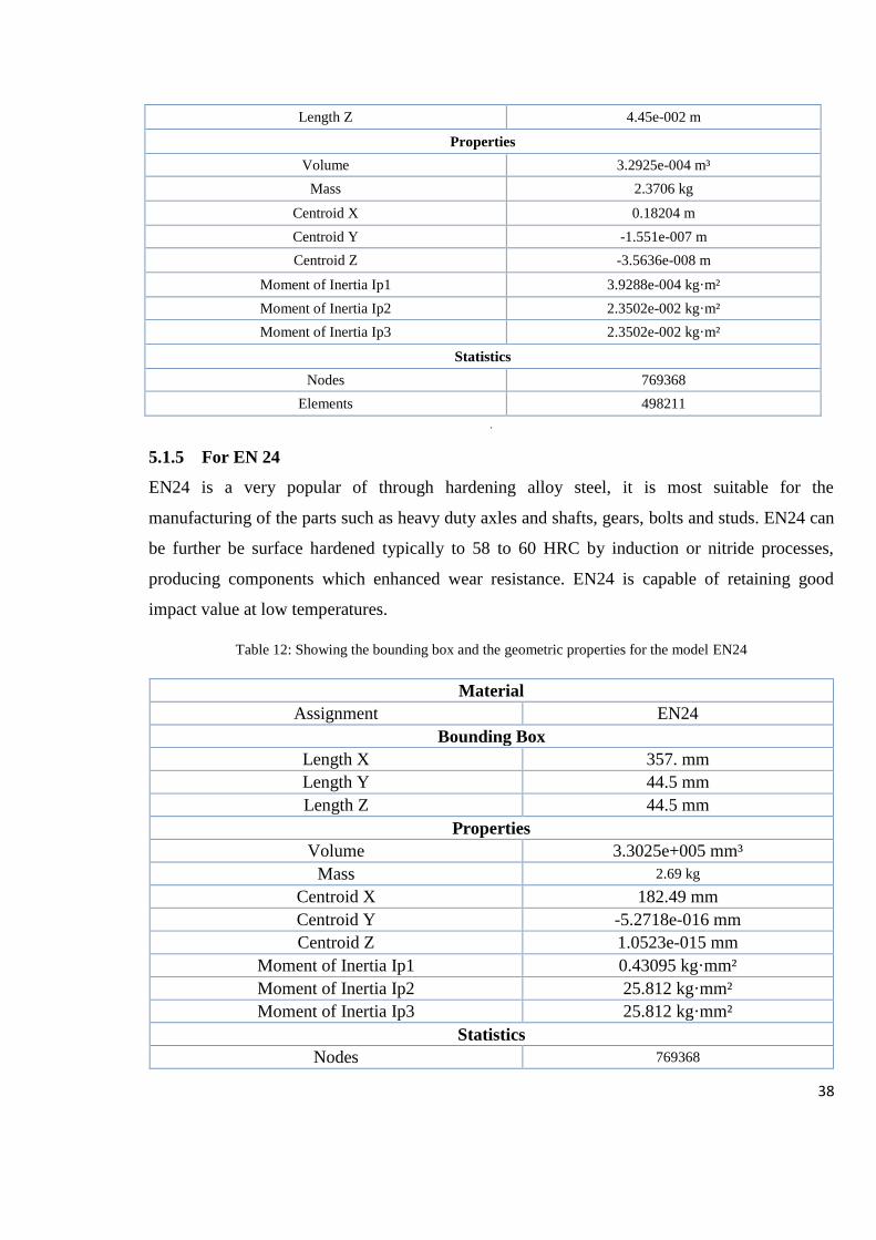
5.1.5 For EN 24
EN24 is a very popular of through hardening alloy steel, it is most suitable for the
manufacturing of the parts such as heavy duty axles and shafts, gears, bolts and studs. EN24 can
be further be surface hardened typically to 58 to 60 HRC by induction or nitride processes,
producing components which enhanced wear resistance. EN24 is capable of retaining good
impact value at low temperatures.
Table 12: Showing the bounding box and the geometric properties for the model EN24
Material
Assignment EN24
Bounding Box
Length X 357. mm
Length Y 44.5 mm
Length Z 44.5 mm
Properties
Volume 3.3025e+005 mm³
Mass 2.69 kg
Centroid X 182.49 mm
Centroid Y -5.2718e-016 mm
Centroid Z 1.0523e-015 mm
Moment of Inertia Ip1 0.43095 kg·mm²
Moment of Inertia Ip2 25.812 kg·mm²
Moment of Inertia Ip3 25.812 kg·mm²
Statistics
Nodes 769368
39
Elements 498211 .
5.1.6 For structural steel:
Table 13: Showing the bounding box and the geometric properties for the model structural steel.
Material
Assignment Structural steel
Bounding Box
Length X 357. mm
Length Y 44.5 mm
Length Z 44.5 mm
Properties
Volume 3.3025e+005 mm³
Mass 2.5846 kg
Centroid X 182.49 mm
Centroid Y -5.2718e-016 mm
Centroid Z 1.0523e-015 mm
Moment of Inertia Ip1 0.43095 kg·mm²
Moment of Inertia Ip2 25.812 kg·mm²
Moment of Inertia Ip3 25.812 kg·mm²
Statistics
Nodes 769368
Elements 498211
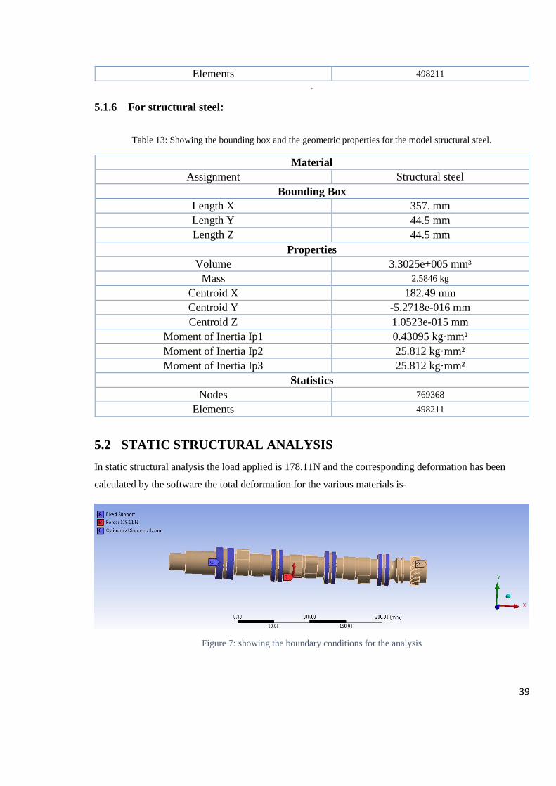
5.2 STATIC STRUCTURAL ANALYSIS
In static structural analysis the load applied is 178.11N and the corresponding deformation has been
calculated by the software the total deformation for the various materials is-
Figure 7: showing the boundary conditions for the analysis

40
5.3 RESULTS
Table 14 : Results - Total deformation, equivalent (von mises) stress and strain.
Materials Equivalent stress
(von mises) Mpa
Equivalent strain (von
mises)
Total deformation
EN8D 2.32×10⁻⁶ - .980 1.86×10⁻¹¹ – 5.02×10⁻⁶ 1.6×10⁻⁵mm -1.49×10⁻⁴mm
EN24 1.86×10⁻⁶- 0.98 1.19×10⁻¹¹ –4.04×10⁻⁶ 1.32×10⁻⁵mm -1.19×10⁻⁴mm
SS (structural steel) 2.32×10⁻⁶-0.98 1.95×10⁻¹¹-5.27×10⁻⁶ 1.74×10⁻⁵mm-1.66×10⁻⁴mm
Cast iron 1.98×10⁻⁶- .97 3.04×10⁻¹¹-9.64×10⁻⁶ 3.15×10⁻⁵mm-2.80×10⁻⁴mm
The equivalent stress and strain in various material has been calculated with total deformation
for each material and the comparison has been done for the best material. We are focussing here
the performance of the engine so for three materials the value of maximum stress has come out
to be same i.e. .98Mpa and the fourth one is also a little offset by .01Mpa i.e. cast iron now to
evaluate a material on the bases of stress is very difficult so we talk about another parameter i.e.
strain .The strain value in EN8D and EN24 are the lowest one and at the same time deformation
in both the material are very less. But since the weight of EN24 is very high than the weight of
EN8D it can’t compensate the factor of performance of engine over weight. So a little
compromization with deformation can be done to gain the total performance of the engine.
Figure 8: Showing the total deformation of camshaft

41
Figure 9: Equivalent stress (Von- mises) of camshaft
Figure 10: Equivalent strain (Von mises) of the camshaft
Figure 11 : Graph showing comparison between mass of different camshafts of different materials
2.5846
2.69
2.5846
2.3706
2.2
2.3
2.4
2.5
2.6
2.7
2.8
EN8D EN24 S.S Cast Iron
Mass (kg)
Mass (kg)
Linear (Mass (kg))

42
5.4 ANALYSIS OF CAMSHAFT IN ROTATING CONDITIONS
5.4.1 Boundary conditions:
Figure 12: boundary conditions for the camshaft in rotating conditions.
For EN8D:
Table 15: Showing the results for EN8D material.
Total deformation Equivalent stress Equivalent strain
Minimum 8.20×10⁻⁵ mm 0.28537 MPa 1.4198e-006 mm/mm
Maximum 7.3881×10⁻⁴ mm 7.5739 MPa 3.6071e-005 mm/mm
For EN8D the total deformation (maximum and minimum) has been calculated using the
ANSYS workbench software. Maximum value of deformation is .0007388mm with 7.573Mpa
stress value.
For EN24:
Table 16: Showing the results for EN24 material.
Total deformation Equivalent stress Equivalent strain
Minimum 6.99×10⁻⁵ mm 0.32777 MPa 1.3095e-006 mm/mm
Maximum 6.2958×10⁻⁴ mm 8.1487 MPa 3.1345e-005 mm/mm
43
For EN24 the value of total deformation is less than the value that has obtained from EN8D but
the value of stress in the camshaft is greater than EN8D. Therefore we have calculated the factor
of safety for both the material which came out to be higher in case of EN8D because of low
value of stress in rotation. It means this material can give a long life in operating conditions, in
comparison to EN24.
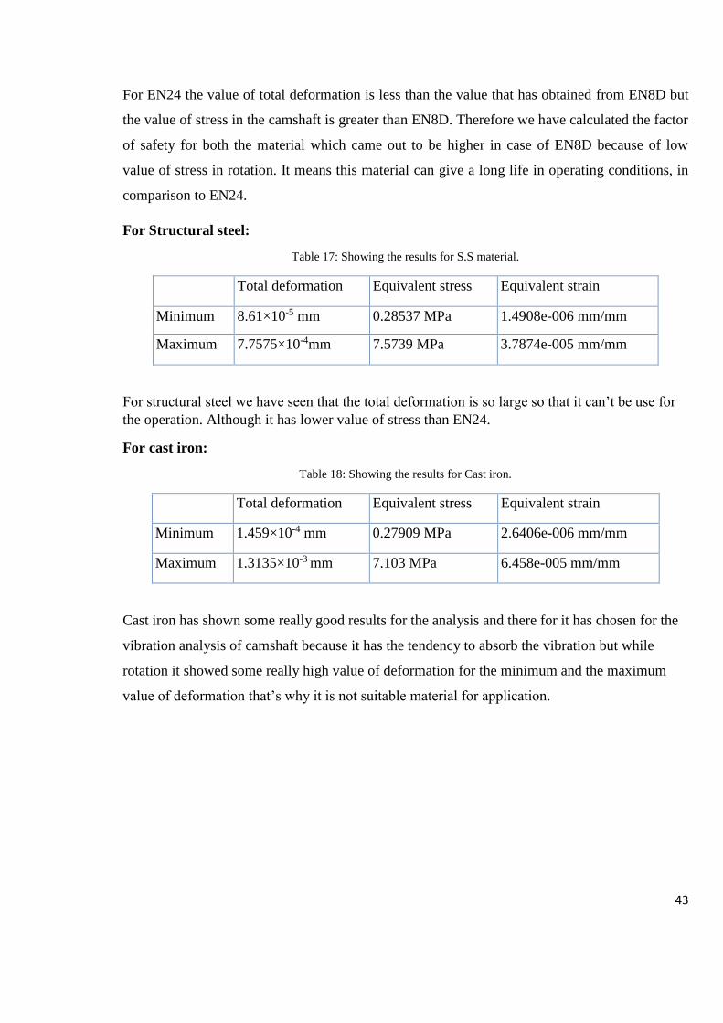
For Structural steel:
Table 17: Showing the results for S.S material.
Total deformation Equivalent stress Equivalent strain
Minimum 8.61×10⁻⁵ mm 0.28537 MPa 1.4908e-006 mm/mm
Maximum 7.7575×10⁻⁴mm 7.5739 MPa 3.7874e-005 mm/mm
For structural steel we have seen that the total deformation is so large so that it can’t be use for
the operation. Although it has lower value of stress than EN24.
For cast iron:
Table 18: Showing the results for Cast iron.
Total deformation Equivalent stress Equivalent strain
Minimum 1.459×10⁻⁴ mm 0.27909 MPa 2.6406e-006 mm/mm
Maximum 1.3135×10⁻³ mm 7.103 MPa 6.458e-005 mm/mm
Cast iron has shown some really good results for the analysis and there for it has chosen for the
vibration analysis of camshaft because it has the tendency to absorb the vibration but while
rotation it showed some really high value of deformation for the minimum and the maximum
value of deformation that’s why it is not suitable material for application.
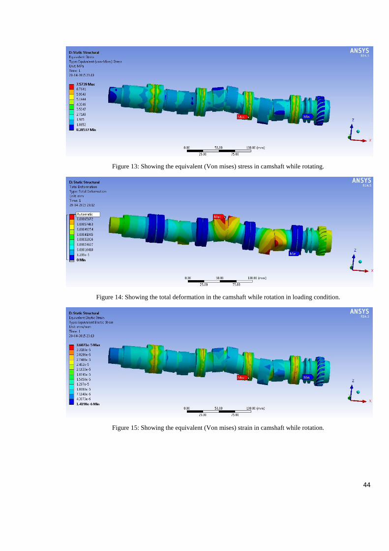
44
Figure 13: Showing the equivalent (Von mises) stress in camshaft while rotating.
Figure 14: Showing the total deformation in the camshaft while rotation in loading condition.
Figure 15: Showing the equivalent (Von mises) strain in camshaft while rotation.
45
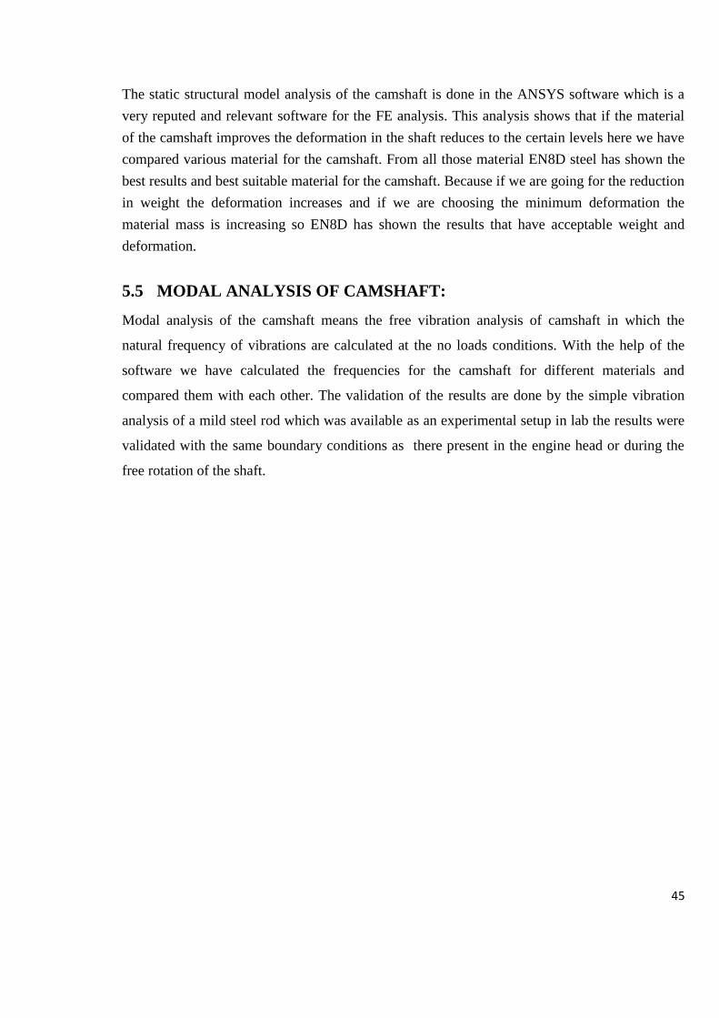
The static structural model analysis of the camshaft is done in the ANSYS software which is a
very reputed and relevant software for the FE analysis. This analysis shows that if the material
of the camshaft improves the deformation in the shaft reduces to the certain levels here we have
compared various material for the camshaft. From all those material EN8D steel has shown the
best results and best suitable material for the camshaft. Because if we are going for the reduction
in weight the deformation increases and if we are choosing the minimum deformation the
material mass is increasing so EN8D has shown the results that have acceptable weight and
deformation.
5.5 MODAL ANALYSIS OF CAMSHAFT:
Modal analysis of the camshaft means the free vibration analysis of camshaft in which the
natural frequency of vibrations are calculated at the no loads conditions. With the help of the
software we have calculated the frequencies for the camshaft for different materials and
compared them with each other. The validation of the results are done by the simple vibration
analysis of a mild steel rod which was available as an experimental setup in lab the results were
validated with the same boundary conditions as there present in the engine head or during the
free rotation of the shaft.

46
5.5.1 EN24:
Following are the natural frequencies at different modes for the material EN24.
Table 19 : Showing the natural frequencies and deformation with different modes of EN24 camshaft
Mode Frequency [Hz] Deformation
1. 17505 64.724 mm
2. 17605 59.219 mm
3. 18131 63.392 mm
4. 18200 59.479 mm
5. 20268 97.121 mm
6. 20493 79.219 mm
5.5.2 END8:
For EN8D following are the natural frequencies obtained with respected deformations.
Table 20: Showing the natural frequencies and deformation with different modes of EN8D camshaft
Mode Frequency [Hz] Deformation
1. 16036 67.055 mm
2. 16137 61.155 mm
3. 16645 65.871 mm
4. 16715 61.475 mm
5. 18593 100.89 mm
6. 18814 81. mm

47
5.5.3 Structural steel:
Following are the natural frequencies obtained for the structural steel camshaft.
Table 21: Showing the natural frequencies and deformation with different modes of SS camshaft
5.5.4 Cast iron:
Following is the table that is obtained for the natural frequencies and the deformation at
different mode shape for cast iron camshaft.
Table 22: Showing the natural frequencies and deformation with different modes of cast iron camshaft
Mode Frequency [Hz] Deformation
1. 12125 69.292 mm
2. 12196 63.329 mm
3. 12567 67.929 mm
4. 12616 63.62 mm
5. 14044 104.07 mm
6. 14204 86.32 mm
Mode Frequency [Hz] Deformation
1. 15650 67.055 mm
2. 15749 61.155 mm
3. 16244 65.871 mm
4. 16312 61.475 mm
5. 18145 100.89 mm
6. 18360 81. mm
48
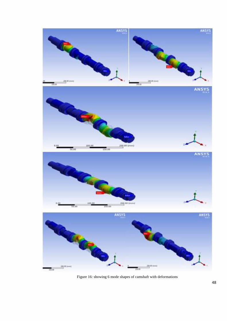
Figure 16: showing 6 mode shapes of camshaft with deformations

49
Figure 17: Graph showing the comparison between the natural frequencies of different material camshaft
5.6 ANALYSIS PROCEDURE:
First step is to prepare the 3D cad model in any of the 3D cad software here we have used the
solidworks for this purpose. Solid modelling is done with exact dimension of a 3 cylinder SI
engine camshaft. Then the solid model is being imported to the ANSYS software using the
given neutral file formats. Then it is opened in the workbench to analyse the analysis procedure
takes 4 steps. But first we have analysed the masses and the deformation in the camshafts with
different materials.
After analysing the various material we can see the material which is having the lowest mass
having the highest value of deformation and the material that have the lowest deformation have
the highest mass. So if the material is to be choose from the given data it is EN8D which is
having the lower weight value and the lower deformation in the operating conditions. For the
vibration analysis the MODAL ANALYSIS in ANSYS Workbench. This process includes the
following four steps.
Pre procedure: this step specifies the 2D CAD geometry of the model in the ANSYS
workbench environment and all the dimensioning of the model is converted according to the
module. Most preferably we should take the same dimensions in the analysis as they were taken
in the cad modelling geometry. Else the values of the results will be much distorted and off the
limits sometimes.
5000
8000
11000
14000
17000
20000
23000
0 1 2 3 4 5 6 7
Natural frequencies
en24 en8d cast iron ss

50
Meshing: Meshing is the process of dividing the model in the small and discreet elements called
the meshing elements, there are various type of meshing elements present in the software like
brick elements, pyramidal, spherical, cubical triangular etc. meshing is done because it is so easy
to calculate the problem for a small element than a bulk material therefore it is said that finer the
mesh better will be the results. For the current project we have employed the mashing according
to the curves and proximity.
Applying loads: this step is so important for the analysis because it defines the boundary for the
results of the problem. And the scope of results are defined in this step. All the loads on the
models and the boundary conditions should be applied at the exact locations for the exact
solutions to the problem.
Post process: This step specifies the results to the problem, first the postprocessor reads the
problem and the boundary conditions then it generates the mathematical model of the problem
then the equation to the solutions are formed and the results are calculated. Then the results are
applied to the geometry to show the final shape of the geometry if it is feasible then it would
generate the final results but if it is not possible then it returns back to the pre-processor to
generate the mathematical model again and run the solution again until the desired solution is
obtained.
Figure 18: Final deformed shape of camshaft.
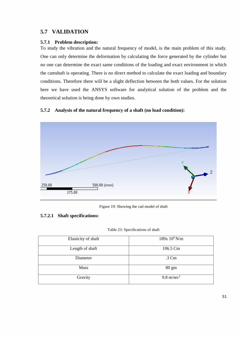
51
5.7 VALIDATION
5.7.1 Problem description:
To study the vibration and the natural frequency of model, is the main problem of this study.
One can only determine the deformation by calculating the force generated by the cylinder but
no one can determine the exact same conditions of the loading and exact environment in which
the camshaft is operating. There is no direct method to calculate the exact loading and boundary
conditions. Therefore there will be a slight deflection between the both values. For the solution
here we have used the ANSYS software for analytical solution of the problem and the
theoretical solution is being done by own studies.
5.7.2 Analysis of the natural frequency of a shaft (no load condition):
Figure 19: Showing the cad model of shaft
5.7.2.1 Shaft specifications:
Table 23: Specifications of shaft
Elasticity of shaft 189x 109 N/m
Length of shaft 106.5 Cm
Diameter .3 Cm
Mass 80 gm
Gravity 9.8 m/sec2
52
The shaft which has been used for the experimental analysis was of mild steel and having a
diameter of 3mmwith a total length of 1.05m. The weight of shaft has given in table 24.
5.7.2.2 Boundary conditions for shaft:
Table 24: Boundary conditions applied
Speed when both ends are
fixed
Speed when simply supported Speed when one end is freed
760 rpm 415rpm 610rpm
Boundary conditions for the shaft can be specify in three modes first when it’s both ends are fixed second
when it’s simply supported and third when both the ends are freed. The rotational speed was given to
shaft in each case and the frequency was calculated for respective cases.
I = π/64 × d4
7. Moment of inertia of cylinder
= π/64 (3×10⁻³)4
= 3.96×10⁻¹²m4
W= weight per unit length
= 0.080×9.8/1.065
=7.36 N/m
8.Natural Frequency (both ends fixed):
Fn= [π/2(n+1/2) √ (gEI)] / WL4
For n=1
Fn=10.152 Hz
For n=2
Fn=28.2 Hz
For n=3
Fn= 55.27 Hz
9.Natural frequency (both ends are supported):
Fn= [π/2(n2) √ (gEI)] / WL4
For n=1
Fn= 4.512 Hz

53
For n=2
Fn= 18.078 Hz
For n=3
Fn= 40.601 Hz
10. Natural frequency (both ends are freed):
Fn= [π/2(n -1/2) √ (gEI)] / WL4
For n=1
Fn= 1.128 Hz
For n=2
Fn= 10.152 Hz
For n=3
Fn= 98.2 Hz
5.8 ANALYTICAL SOLUTION:
Analytical solution with boundary conditions same as the camshaft.
5.8.1 Boundary conditions:
Object Name Shaft
State Meshed
Definition
Stiffness Behaviour Flexible
Coordinate System Default Coordinate System
Reference Temperature By Environment
Material
Assignment MS
Nonlinear Effects Yes
Thermal Strain Effects Yes
Bounding Box
Length X 5. mm
Length Y 5. mm
Length Z 1085. mm
Properties
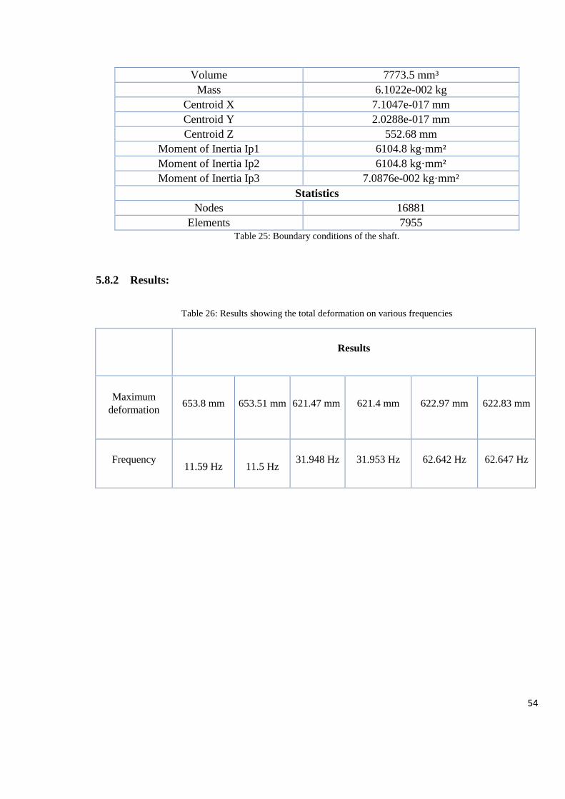
54
Volume 7773.5 mm³
Mass 6.1022e-002 kg
Centroid X 7.1047e-017 mm
Centroid Y 2.0288e-017 mm
Centroid Z 552.68 mm
Moment of Inertia Ip1 6104.8 kg·mm²
Moment of Inertia Ip2 6104.8 kg·mm²
Moment of Inertia Ip3 7.0876e-002 kg·mm²
Statistics
Nodes 16881
Elements 7955 Table 25: Boundary conditions of the shaft.
5.8.2 Results:
Table 26: Results showing the total deformation on various frequencies
Results
Maximum
deformation
653.8 mm
653.51 mm 621.47 mm 621.4 mm 622.97 mm 622.83 mm
Frequency
11.59 Hz
11.5 Hz 31.948 Hz 31.953 Hz 62.642 Hz 62.647 Hz

55
Figure 20: Mode shapes of shaft.
5.8.3 Conclusion:
Results shows that the natural frequency for the mild steel shaft that is calculated theoretically are
matched with a slight margin of offset from natural frequencies those are being calculated by the
software ANSYS. Therefore the same boundary conditions would also be applicable for the camshaft we
are analysing here. Hence the calculations are validated both analytically and theoretically.
Values of frequencies from experiments (Hz) Values of frequencies from the software
(ANSYS) in (Hz)
10.152 11.594
11.596
28.2 31.948
31.953
55.27 62.642
62.647
Table 27: Comparison of theoretical and analytical values.
56
CHAPTER- 6
6 CONCLUSION
The FE analysis of camshaft has been done and we have found the material that is appropriate
for the fabrication of the camshaft it may be cost effective and easily available in the market
here we have seen the various parameters on which the manufacturing and the application of the
components relies but sometimes when we talk about the performance we need the least
disturbed element or the component in the system then according to the performance point of
view the camshaft of cast iron is a suitable option for us but it also have some major
disadvantages it is having the high weight and larger deformation with time but very low value
of vibrations as we all know cast iron is the best vibration absorber element but it doesn’t have
that suitable strength which is needed for application. Now if we see the weight with
performance the structural steel and EN24 steel are the good option for the manufacturers but if
we see it from the mechanical point of view they doesn’t seem to have the good option while
working conditions they shows very large deformation values at the resonance conditions. Now
there is only one material that we are left with here i.e. EN8D. This material shows the good
results rather the least deformation at the resonance frequencies and have light weight than
structural steel and EN24. Have good torsional strength but higher than the cast iron if we have
to choose a material among all these four elements one have to compromise between the
performance and the weight of the component so we can conclude that the EN8D is the material
which may be used to manufacturing of camshaft.
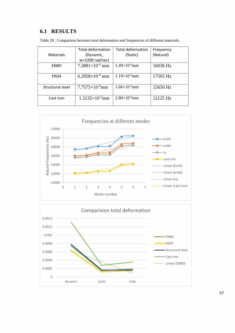
57
6.1 RESULTS
Table 28 : Comparison between total deformation and frequencies of different materials.
Materials
Total deformation (Dynamic,
w=2200 rad/sec)
Total deformation (Static)
Frequency (Natural)
EN8D 7.3881×10⁻⁴ mm 1.49×10⁻⁴mm
16036 Hz
EN24 6.2958×10⁻⁴ mm
1.19×10⁻⁴mm
17505 Hz
Structural steel 7.7575×10⁻⁴mm
1.66×10⁻⁴mm
15650 Hz
Cast iron 1.3135×10⁻³mm 2.80×10⁻⁴mm
12125 Hz
10000
12000
14000
16000
18000
20000
22000
0 1 2 3 4 5 6 7
Nat
ura
l fre
qu
enci
es (
Hz)
Mode number
Frequencies at different modes
En24
en8d
ss
cast iron
Linear (En24)
Linear (en8d)
Linear (ss)
Linear (cast iron)
0
0.0002
0.0004
0.0006
0.0008
0.001
0.0012
0.0014
dynamic static hole
Comparision total deformation
EN8D
EN24
Structural steel
Cast iron
Linear (EN8D)

58
From the Modal analysis and the static structural analysis we have seen that the EN8D material
have shown the best results it has shown the least deformation in the corresponding frequencies
and having the weight higher than the cast iron but lower than the structural steel and EN24. It
has shown the least stress value of 2.32×10⁻⁶Mpa and a least deformation of 1.6×10⁻⁵mm to
1.49×10⁻⁴mm. so EN8D is the suitable material for the camshaft manufacturing.
6.2 FUTURE SCOPE
With the help of this work the manufacturing processes for the camshaft can be decided. With
this work one can do more analysis related to the camshaft. For another application the material
selection for camshaft become easier for the manufacturer
6.3 RECOMMENDATIONS
If you want to get a higher performance with the light weight we can recommend the part with
material EN8D to anyone but if one wants the lower vibration with compromization with weight
one can choose the structural steel or cast iron camshaft.
59
CHAPTER -7
7 REFERENCES:
[1] S.-W. Chyuan, "Finite element simulation of a twin-cam 16-valve cylinder," Finite Elements in
Analysis and Design, pp. 199-212, 2000.
[2] H. X. a. J. W. Zu, “Cam profile optimization for a new cam drive,” Journal of Mechanical Science
and Technology, pp. 2592-2602, 2009.
[3] S. jhonson, design of machinery.
[4] V. A.S.Dhavale, “Study of Modeling and Fracture Analysis of Camshaft,” International Journal of
Engineering Research and Applications, pp. 835-842, November- December 2012.
[5] P. D. M. S. H. G. J. S. B. Mahesh R. Mali, “Design Optimization of Cam & Follower Mechanism of
an Internal Combustion Engine for Improving the Engine Efficiency,” Modern Mechanical
Engineering, pp. 114-119, August 2012.
[6] D.-I. M. M. d. S. S. C. Philippe de Abreu Duque, “Contact pressure between cams and roller
followers through Finite Elements Method (FEM) in assembled camshafts,” in Virtual Powertrain
Conferences, Neumayer Tekfor Tech Center Brazil.
[7] K. K. D. Dave Marmik M., “Static Structure Analysis of Diesel Engine Camshaft,”
INTERNATIONAL JOURNAL OF SCIENTIFIC RESEARCH, pp. 208-209, May 2013.
[8] J. A. escobar, “stress and fatigue analysis of camshaft lobes,” virginia polytechnique institute of
state university, virginia, November,1996.
[9] W. S. Ulf Andresen, “A SIMPLE CAM DESIGN PROCEDURE FOR AUTOMATIC SCREW,”
Symposium on Flexible Automation, pp. 10-14, July,2002.
[10] R. B. L. K. Z. S. J. W. B. L. P. Folega, “Impact of the cam and follower cooperation and of
lubrication on the cam wear,” Archives of material science and engineering, pp. 158-163, december
2012.
[11] T. C. P. R. V. Wanjari, “Design and Analysis of Camshaft by Changing Parameters which Causes
Failure,” International Journal of Science and Modern Engineering, pp. 32-35, May 2013.
[12] L. F. C. A. a. W. B. Li Ping, “Fracture analysis of chilled cast iron,” CHINA FOUNDRY, pp. 104-
108, february ,2009.
[13] K. M. Vivekanandan.P, “Modelling, Design and Finite Element Analysis of Cam Shaft,”
International Journal of Current Engineering and Technology, pp. Vol.3, No.1, 1March 2013.
[14] P. sahoo, engineering tribology, delhi: PHI learning pvt. ltd., 2000.
[15] N. D. A. S. P. F. S.G.THORAT, “DESIGN & ANALYSIS OF CAMSHAFT,” in IRF International
60
Conference, Pune, 15th June-2014, Pune, India.
[16] T. C. P. R. V. Wanjari, “Design and Analysis of Camshaft by Changing Parameters which Causes
Failure,” International Journal of Science and Modern Engineering, pp. Volume-1, Issue-6, May
2013.
[17] M. H. B. OTHMAN, ANALYSIS OF VIBRATION IN CAM FOLLOWER SYSTEM, PAHANG:
UNIVERSITI MALAYSIA PAHANG, NOVEMBER 2009.
[18] C. moon, Cam design- a manual for engineers designers and draftmen, easton, penna: CAMCO,
1961.
[19] i. t. N. a. methods, Mechanical Behaviour and Testing Of Materials.
[20] Düsseldorf, “Efficient machining of camshaft and crankshaft,” in Efficient machining , Sandvikens
Tryckeri, sweden, sandvic coroment, 2003, pp. 229-243.
[21] K. Deb, Optimization for engineering design, an efficient constraint handling method for genetic
algorithms,.
[22] J. S. Brader, “Development of a Piezoelectric Controlled Hydraulic Actuator for a Camless Engine,”
Boston University, boston, 1995.
[23] C. D. Boor, A Practical Guide to Splines., New york: Springer verlag, 1978.
[24] V. D. A. Kolchin, Design of automotive engines, Moscow: MIR publishers Moscow, 1984.
[25] “Life Assessment of the Camshaft in a Heavy Duty Diesel Engine using Flexible Multibody
Dynamics,” INTERNATIONAL COUNCIL ON COMBUSTION ENGINES, p. Paper No. 292, 2010.