Embed Size (px)
DESCRIPTION
Fineblanking is a process that provides parts with smooth edges and high accuracy. Because of the stability and precision of the process many secondary operations can be eliminated. These include:· Grinding · Milling · Broaching · Reaming · Gear Hobbing · Forming · Shaving · Leveling
Citation preview
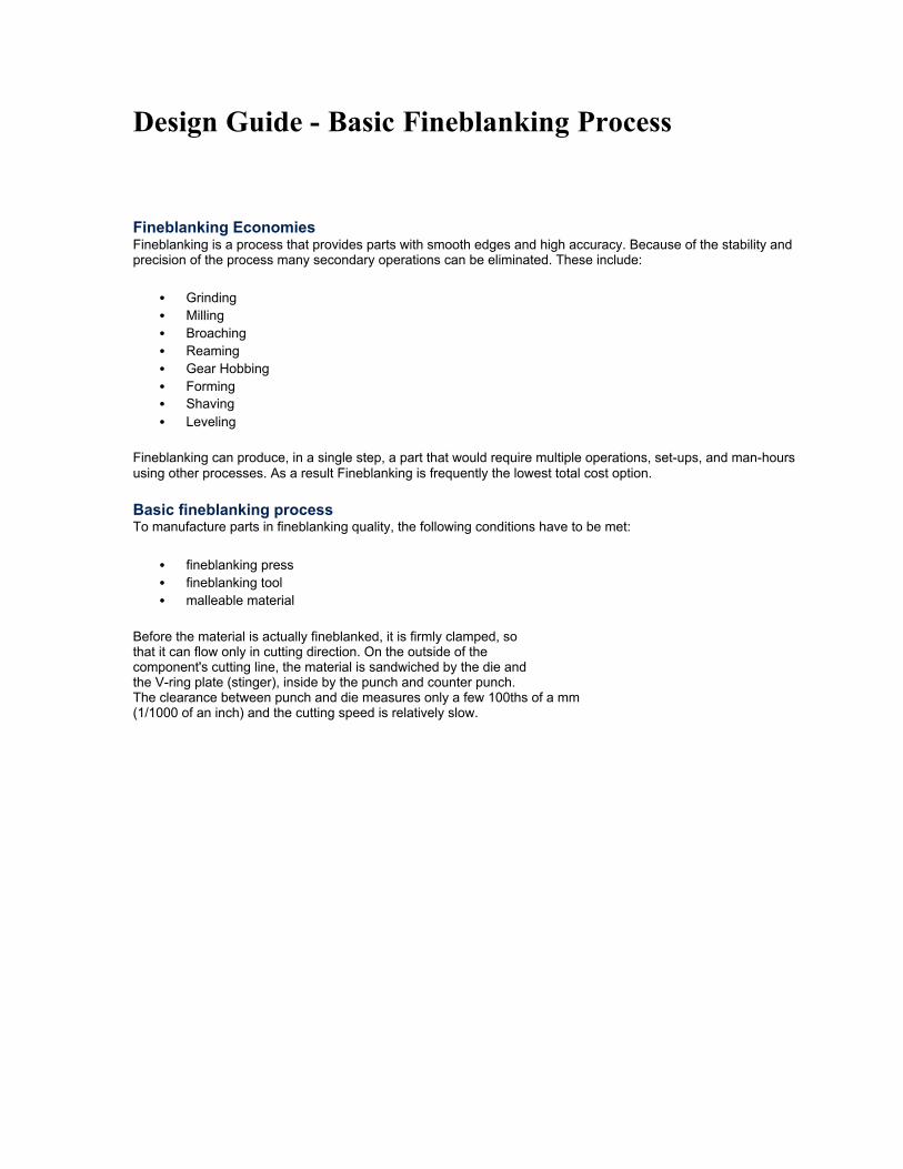
Design Guide - Basic Fineblanking Process Fineblanking Economies Fineblanking is a process that provides parts with smooth edges and high accuracy. Because of the stability and precision of the process many secondary operations can be eliminated. These include:
• Grinding • Milling • Broaching • Reaming • Gear Hobbing • Forming • Shaving • Leveling
Fineblanking can produce, in a single step, a part that would require multiple operations, set-ups, and man-hours using other processes. As a result Fineblanking is frequently the lowest total cost option.
Basic fineblanking process To manufacture parts in fineblanking quality, the following conditions have to be met:
• fineblanking press • fineblanking tool • malleable material
Before the material is actually fineblanked, it is firmly clamped, so that it can flow only in cutting direction. On the outside of the component's cutting line, the material is sandwiched by the die and the V-ring plate (stinger), inside by the punch and counter punch. The clearance between punch and die measures only a few 100ths of a mm (1/1000 of an inch) and the cutting speed is relatively slow.
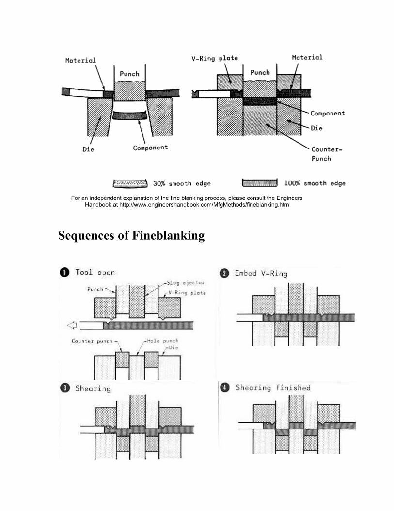
For an independent explanation of the fine blanking process, please consult the Engineers Handbook at http://www.engineershandbook.com/MfgMethods/fineblanking.htm
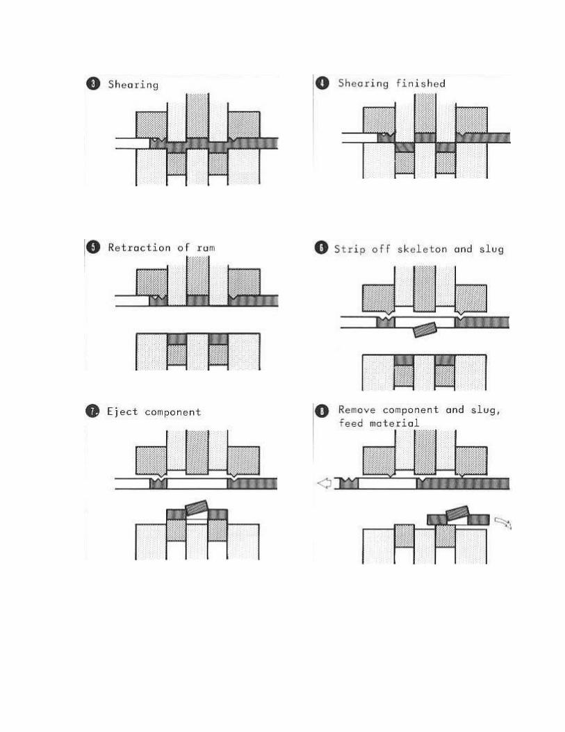
Sequences of Fineblanking
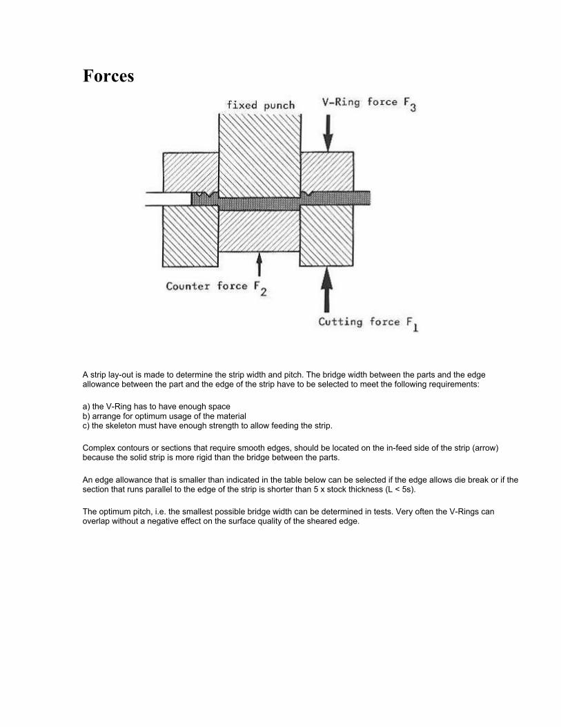
Forces
A strip lay-out is made to determine the strip width and pitch. The bridge width between the parts and the edge allowance between the part and the edge of the strip have to be selected to meet the following requirements:
a) the V-Ring has to have enough space b) arrange for optimum usage of the material c) the skeleton must have enough strength to allow feeding the strip.
Complex contours or sections that require smooth edges, should be located on the in-feed side of the strip (arrow) because the solid strip is more rigid than the bridge between the parts.
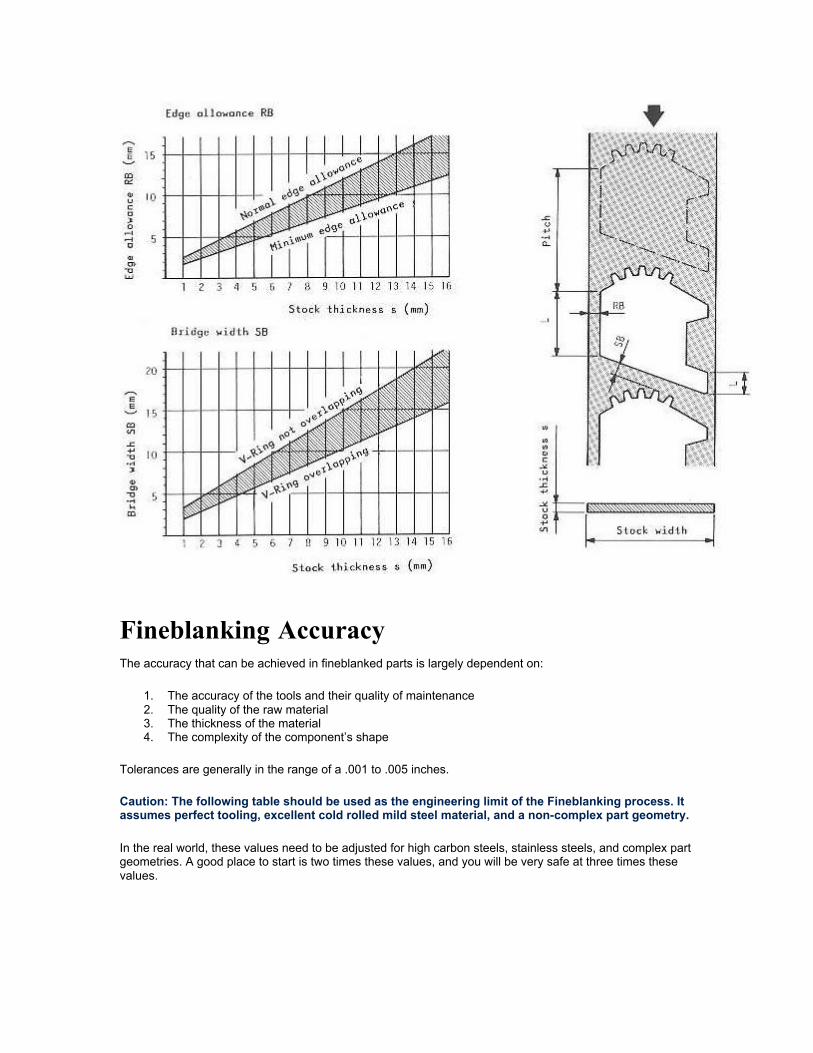
An edge allowance that is smaller than indicated in the table below can be selected if the edge allows die break or if the section that runs parallel to the edge of the strip is shorter than 5 x stock thickness (L < 5s).
The optimum pitch, i.e. the smallest possible bridge width can be determined in tests. Very often the V-Rings can overlap without a negative effect on the surface quality of the sheared edge.
Fineblanking Accuracy The accuracy that can be achieved in fineblanked parts is largely dependent on:
1. The accuracy of the tools and their quality of maintenance 2. The quality of the raw material 3. The thickness of the material 4. The complexity of the component’s shape
Tolerances are generally in the range of a .001 to .005 inches.
Caution: The following table should be used as the engineering limit of the Fineblanking process. It assumes perfect tooling, excellent cold rolled mild steel material, and a non-complex part geometry.
In the real world, these values need to be adjusted for high carbon steels, stainless steels, and complex part geometries. A good place to start is two times these values, and you will be very safe at three times these values.
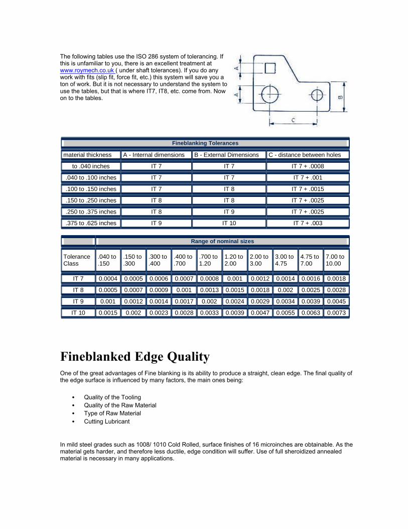
The following tables use the ISO 286 system of tolerancing. If this is unfamiliar to you, there is an excellent treatment at www.roymech.co.uk ( under shaft tolerances). If you do any work with fits (slip fit, force fit, etc.) this system will save you a ton of work. But it is not necessary to understand the system to use the tables, but that is where IT7, IT8, etc. come from. Now on to the tables.
Fineblanked Edge Quality One of the great advantages of Fine blanking is its ability to produce a straight, clean edge. The final quality of the edge surface is influenced by many factors, the main ones being:
• Quality of the Tooling • Quality of the Raw Material • Type of Raw Material • Cutting Lubricant
In mild steel grades such as 1008/ 1010 Cold Rolled, surface finishes of 16 microinches are obtainable. As the material gets harder, and therefore less ductile, edge condition will suffer. Use of full sheroidized annealed material is necessary in many applications.
Fineblanking Tolerances
material thickness A - Internal dimensions B - External Dimensions C - distance between holes
to .040 inches IT 7 IT 7 IT 7 + .0008
.040 to .100 inches IT 7 IT 7 IT 7 + .001
.100 to .150 inches IT 7 IT 8 IT 7 + .0015
.150 to .250 inches IT 8 IT 8 IT 7 + .0025
.250 to .375 inches IT 8 IT 9 IT 7 + .0025
.375 to .625 inches IT 9 IT 10 IT 7 + .003
Range of nominal sizes
Tolerance Class
.040 to
.150 .150 to .300
.300 to
.400 .400 to .700
.700 to 1.20
1.20 to 2.00
2.00 to 3.00
3.00 to 4.75
4.75 to 7.00
7.00 to 10.00
IT 7 0.0004 0.0005 0.0006 0.0007 0.0008 0.001 0.0012 0.0014 0.0016 0.0018
IT 8 0.0005 0.0007 0.0009 0.001 0.0013 0.0015 0.0018 0.002 0.0025 0.0028
IT 9 0.001 0.0012 0.0014 0.0017 0.002 0.0024 0.0029 0.0034 0.0039 0.0045
IT 10 0.0015 0.002 0.0023 0.0028 0.0033 0.0039 0.0047 0.0055 0.0063 0.0073
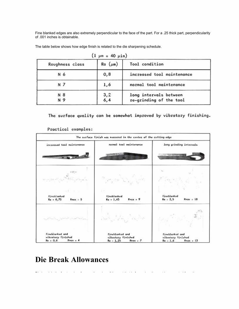
Fine blanked edges are also extremely perpendicular to the face of the part. For a .25 thick part, perpendicularity of .001 inches is obtainable.
The table below shows how edge finish is related to the die sharpening schedule.
Die Break Allowances Die break is the fractured surface on the edge of the part that is formed as the part is separated from the strip. A key advantage to fineblanking is that this die break can be eliminated or greatly reduced.
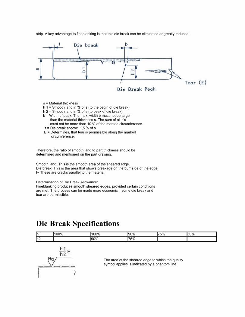
strip. A key advantage to fineblanking is that this die break can be eliminated or greatly reduced.
s = Material thickness h 1 = Smooth land in % of s (to the begin of die break) h 2 = Smooth land in % of s (to peak of die break) b = Width of peak. The max. width b must not be larger than the material thickness s. The sum of all b's must not be more than 10 % of the marked circumference. t = Die break approx. 1,5 % of s. E = Determines, that tear is permissible along the marked circumference.
Therefore, the ratio of smooth land to part thickness should be determined and mentioned on the part drawing.
Smooth land: This is the smooth area of the sheared edge. Die break: This is the area that shows breakage on the burr side of the edge. I~ These are cracks parallel to the material.
Determination of Die Break Allowance: Fineblanking produces smooth sheared edges, provided certain conditions are met. The process can be made more economic if some die break and tear are permissible.
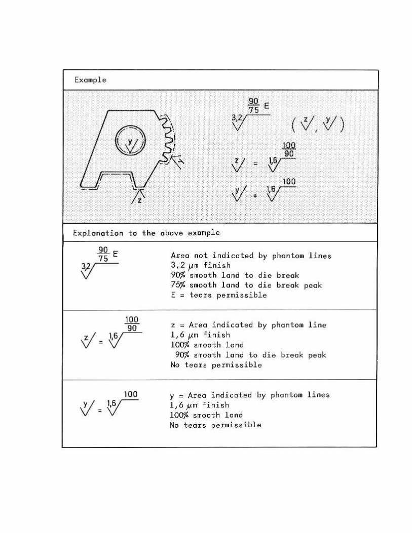
Die Break Specifications hl 100% 100% 90% 75% 50% h2 90% 75%
The area of the sheared edge to which the quality symbol applies is indicated by a phantom line.
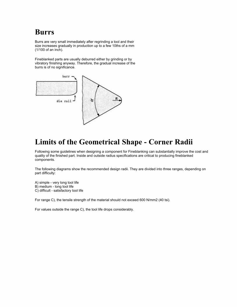
Burrs Burrs are very small immediately after regrinding a tool and their size increases gradually in production up to a few 10ths of a mm (1/100 of an inch).
Fineblanked parts are usually deburred either by grinding or by vibratory finishing anyway. Therefore, the gradual increase of the burrs is of no significance.
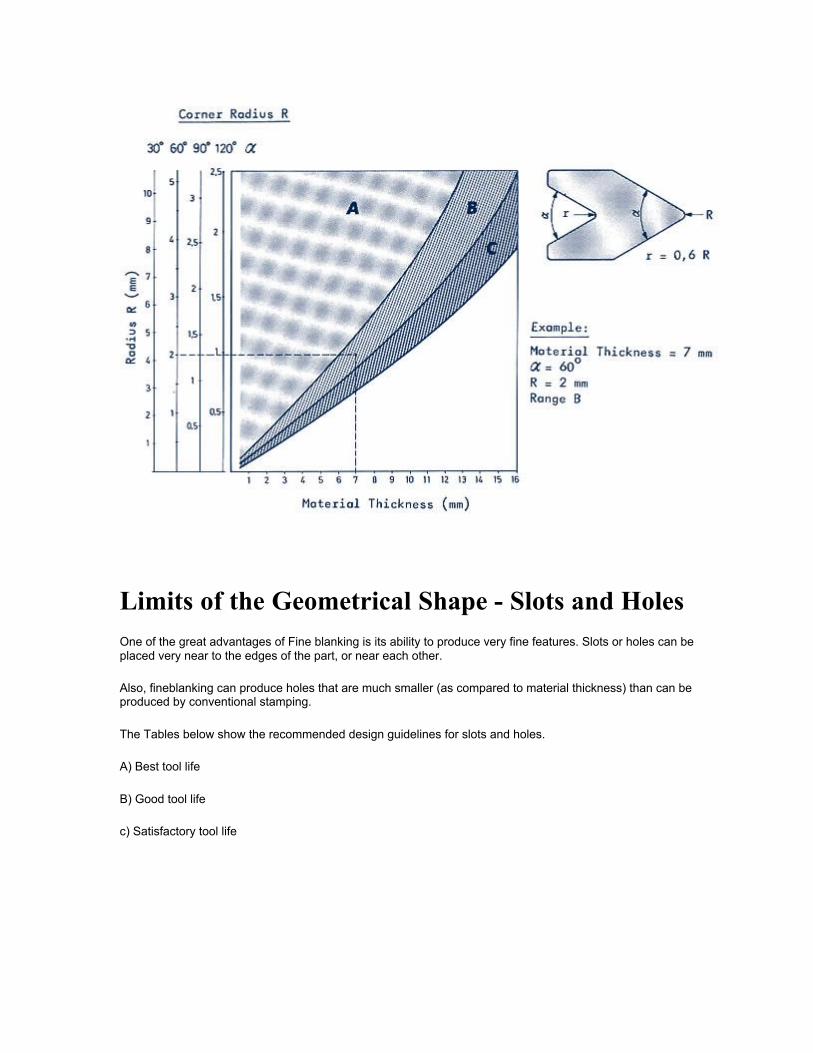
Limits of the Geometrical Shape - Corner Radii Following some guidelines when designing a component for Fineblanking can substantially improve the cost and quality of the finished part. Inside and outside radius specifications are critical to producing fineblanked components.
The following diagrams show the recommended design radii. They are divided into three ranges, depending on part difficulty:
A) simple - very long tool life B) medium - long tool life C) difficult - satisfactory tool life
For range C), the tensile strength of the material should not exceed 600 N/mm2 (40 tsi).
For values outside the range C), the tool life drops considerably.
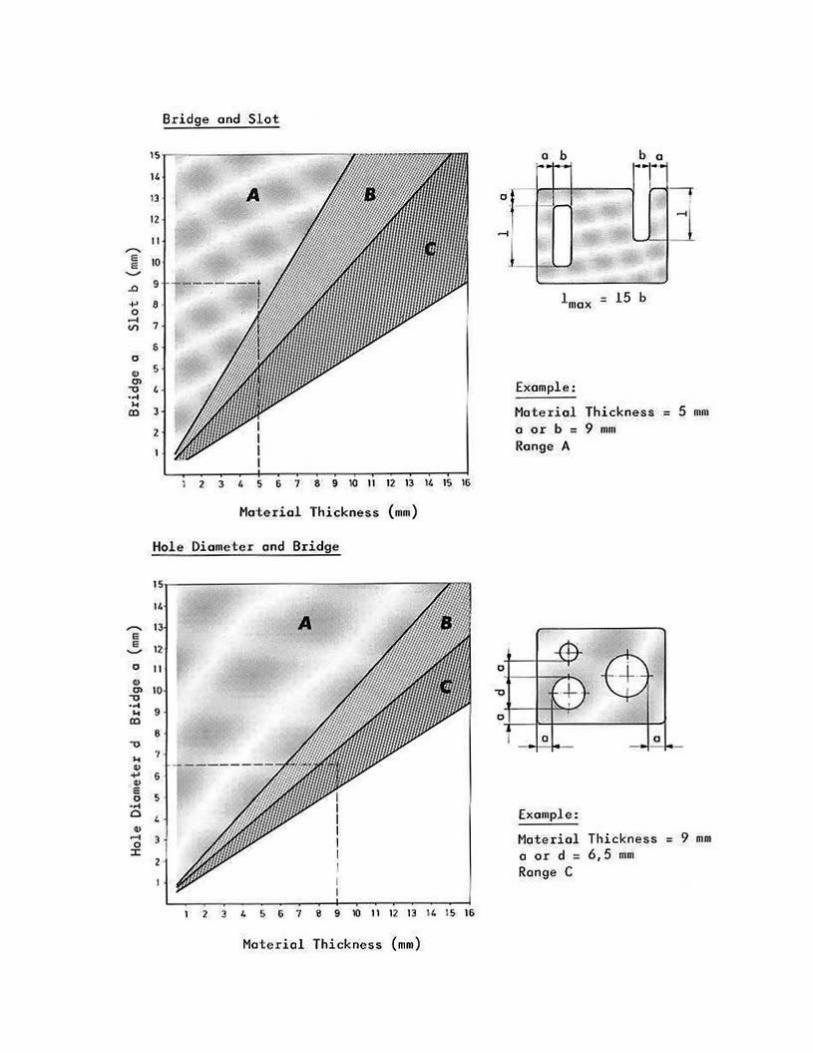
Limits of the Geometrical Shape - Slots and Holes One of the great advantages of Fine blanking is its ability to produce very fine features. Slots or holes can be placed very near to the edges of the part, or near each other.
Also, fineblanking can produce holes that are much smaller (as compared to material thickness) than can be produced by conventional stamping.
The Tables below show the recommended design guidelines for slots and holes.
A) Best tool life
B) Good tool life
c) Satisfactory tool life
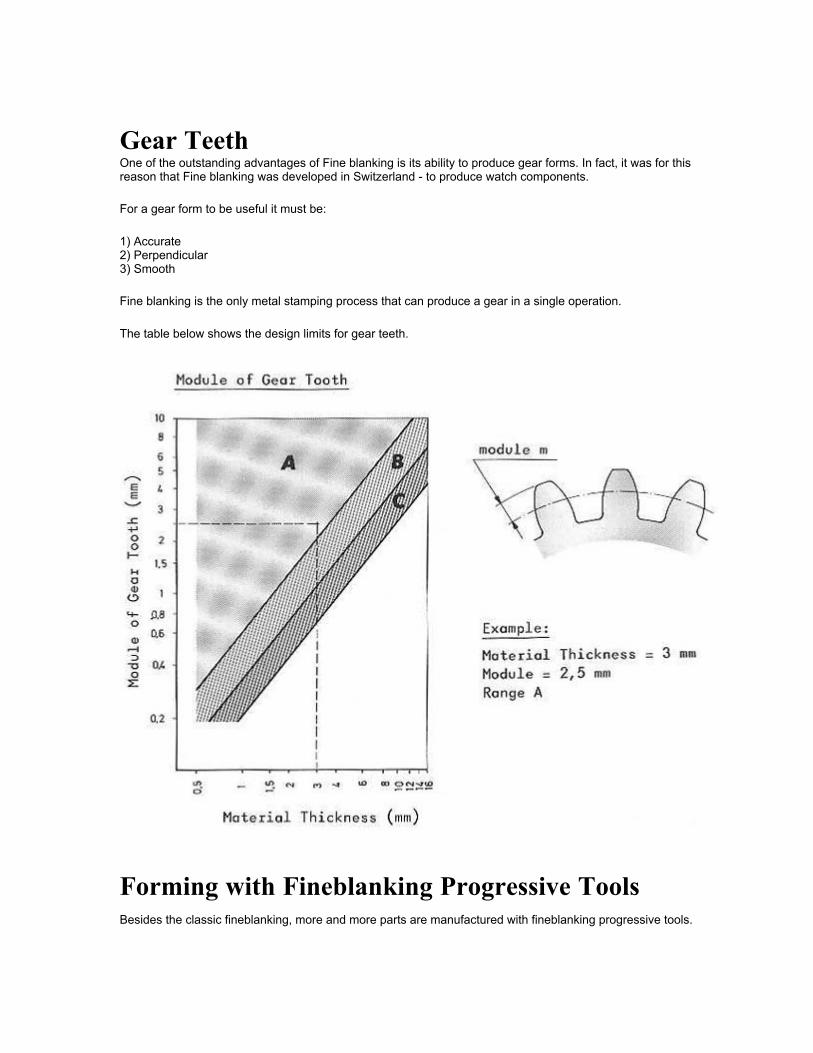
Gear Teeth One of the outstanding advantages of Fine blanking is its ability to produce gear forms. In fact, it was for this reason that Fine blanking was developed in Switzerland - to produce watch components.
For a gear form to be useful it must be:
1) Accurate 2) Perpendicular 3) Smooth
Fine blanking is the only metal stamping process that can produce a gear in a single operation.
The table below shows the design limits for gear teeth.
Forming with Fineblanking Progressive Tools Besides the classic fineblanking, more and more parts are manufactured with fineblanking progressive tools.
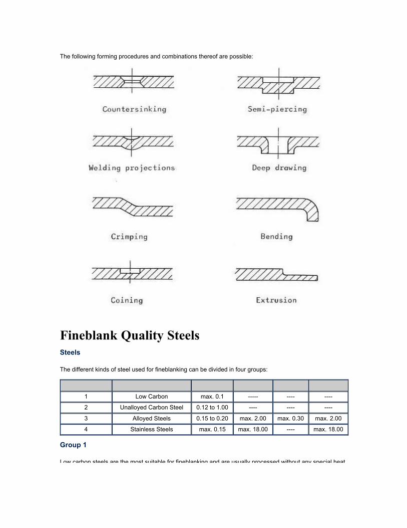
The following forming procedures and combinations thereof are possible:
Fineblank Quality Steels Steels
The different kinds of steel used for fineblanking can be divided in four groups:
Group of Steel Material C % Cr % Mo% Ni%
1 Low Carbon max. 0.1 ----- ---- ----
2 Unalloyed Carbon Steel 0.12 to 1.00 ---- ---- ----
3 Alloyed Steels 0.15 to 0.20 max. 2.00 max. 0.30 max. 2.00
4 Stainless Steels max. 0.15 max. 18.00 ---- max. 18.00
Group 1
Low carbon steels are the most suitable for fineblanking and are usually processed without any special heat treatment.
treatment.
Group 2
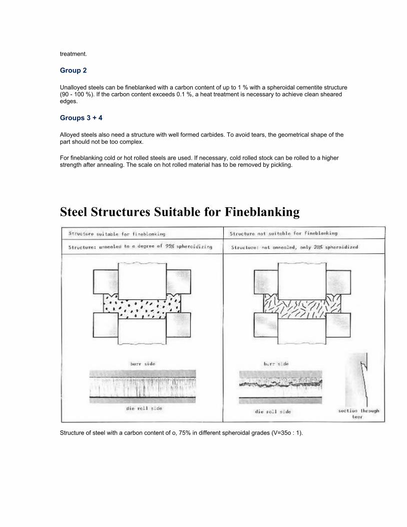
Unalloyed steels can be fineblanked with a carbon content of up to 1 % with a spheroidal cementite structure (90 - 100 %). If the carbon content exceeds 0.1 %, a heat treatment is necessary to achieve clean sheared edges.
Groups 3 + 4
Alloyed steels also need a structure with well formed carbides. To avoid tears, the geometrical shape of the part should not be too complex.
For fineblanking cold or hot rolled steels are used. If necessary, cold rolled stock can be rolled to a higher strength after annealing. The scale on hot rolled material has to be removed by pickling.
Steel Structures Suitable for Fineblanking
Structure of steel with a carbon content of o, 75% in different spheroidal grades (V=35o : 1).
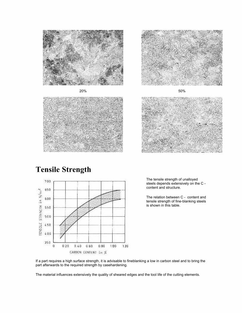
20% 50%
Tensile Strength
The tensile strength of unalloyed steels depends extensively on the C - content and structure.
The relation between C - content and tensile strength of fine-blanking steels is shown in this table.
If a part requires a high surface strength, it is advisable to fineblanking a low in carbon steel and to bring the part afterwards to the required strength by casehardening.
The material influences extensively the quality of sheared edges and the tool life of the cutting elements.
Fineblanking becomes more difficult:
• with increasing tensile strength (shearing strength) • with increasing C content • with increasing alloying content • with decreasing spheroidal cementite structure • with decreasing cleanliness of stock surface (e.g. scale)
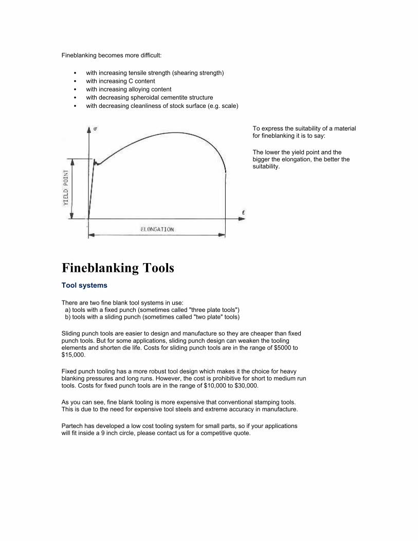
To express the suitability of a material for fineblanking it is to say:
The lower the yield point and the bigger the elongation, the better the suitability.
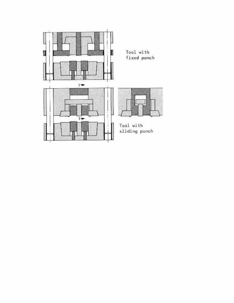
Fineblanking Tools Tool systems
There are two fine blank tool systems in use: a) tools with a fixed punch (sometimes called "three plate tools") b) tools with a sliding punch (sometimes called "two plate" tools)
Sliding punch tools are easier to design and manufacture so they are cheaper than fixed punch tools. But for some applications, sliding punch design can weaken the tooling elements and shorten die life. Costs for sliding punch tools are in the range of $5000 to $15,000.
Fixed punch tooling has a more robust tool design which makes it the choice for heavy blanking pressures and long runs. However, the cost is prohibitive for short to medium run tools. Costs for fixed punch tools are in the range of $10,000 to $30,000.
As you can see, fine blank tooling is more expensive that conventional stamping tools. This is due to the need for expensive tool steels and extreme accuracy in manufacture.
Partech has developed a low cost tooling system for small parts, so if your applications will fit inside a 9 inch circle, please contact us for a competitive quote.
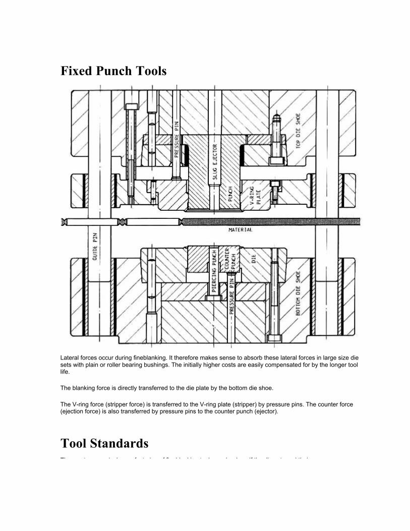
Fixed Punch Tools
Lateral forces occur during fineblanking. It therefore makes sense to absorb these lateral forces in large size die sets with plain or roller bearing bushings. The initially higher costs are easily compensated for by the longer tool life.
The blanking force is directly transferred to the die plate by the bottom die shoe.
The V-ring force (stripper force) is transferred to the V-ring plate (stripper) by pressure pins. The counter force (ejection force) is also transferred by pressure pins to the counter punch (ejector).
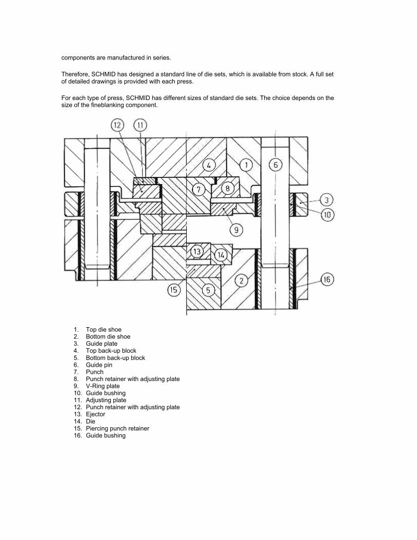
Tool Standards The most economical manufacturing of fineblanking tools can be done if the die sets and their components are manufactured in series.
components are manufactured in series.
Therefore, SCHMID has designed a standard line of die sets, which is available from stock. A full set of detailed drawings is provided with each press.
For each type of press, SCHMID has different sizes of standard die sets. The choice depends on the size of the fineblanking component.
1. Top die shoe 2. Bottom die shoe 3. Guide plate 4. Top back-up block 5. Bottom back-up block 6. Guide pin 7. Punch 8. Punch retainer with adjusting plate 9. V-Ring plate 10. Guide bushing 11. Adjusting plate 12. Punch retainer with adjusting plate 13. Ejector 14. Die 15. Piercing punch retainer 16. Guide bushing
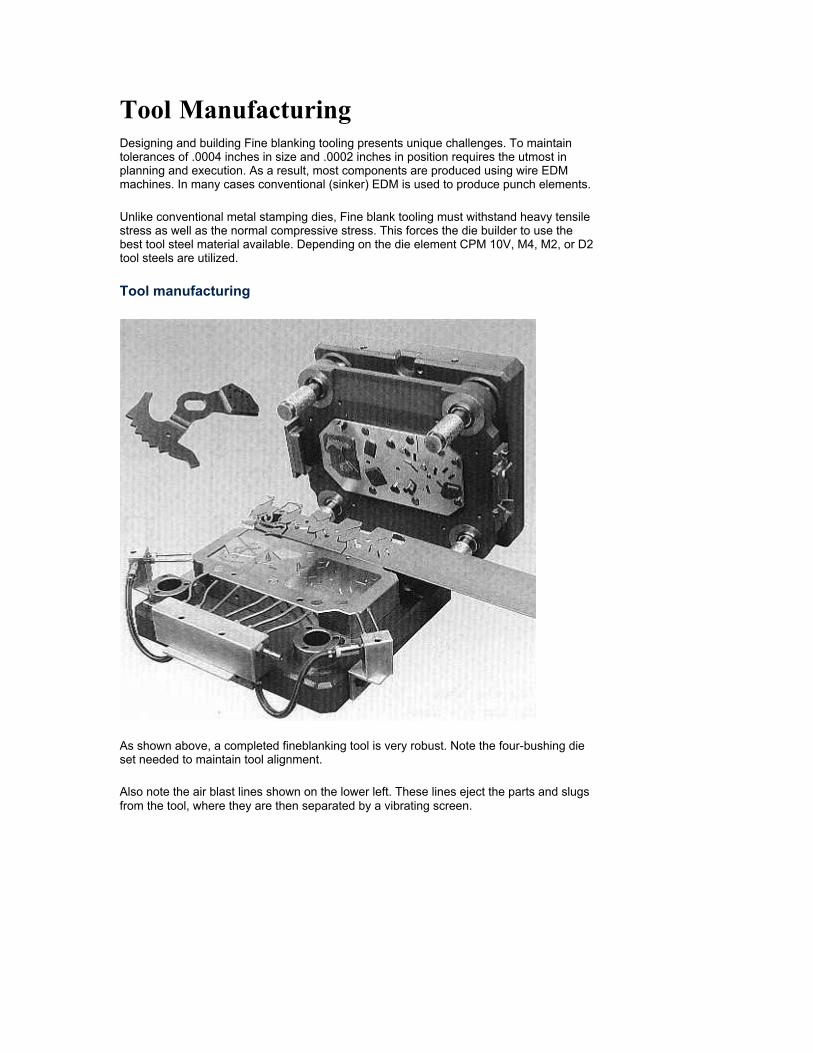
Tool Manufacturing Designing and building Fine blanking tooling presents unique challenges. To maintain tolerances of .0004 inches in size and .0002 inches in position requires the utmost in planning and execution. As a result, most components are produced using wire EDM machines. In many cases conventional (sinker) EDM is used to produce punch elements.
Unlike conventional metal stamping dies, Fine blank tooling must withstand heavy tensile stress as well as the normal compressive stress. This forces the die builder to use the best tool steel material available. Depending on the die element CPM 10V, M4, M2, or D2 tool steels are utilized.
Tool manufacturing
As shown above, a completed fineblanking tool is very robust. Note the four-bushing die set needed to maintain tool alignment.
Also note the air blast lines shown on the lower left. These lines eject the parts and slugs from the tool, where they are then separated by a vibrating screen.

Methods of Tool Construction
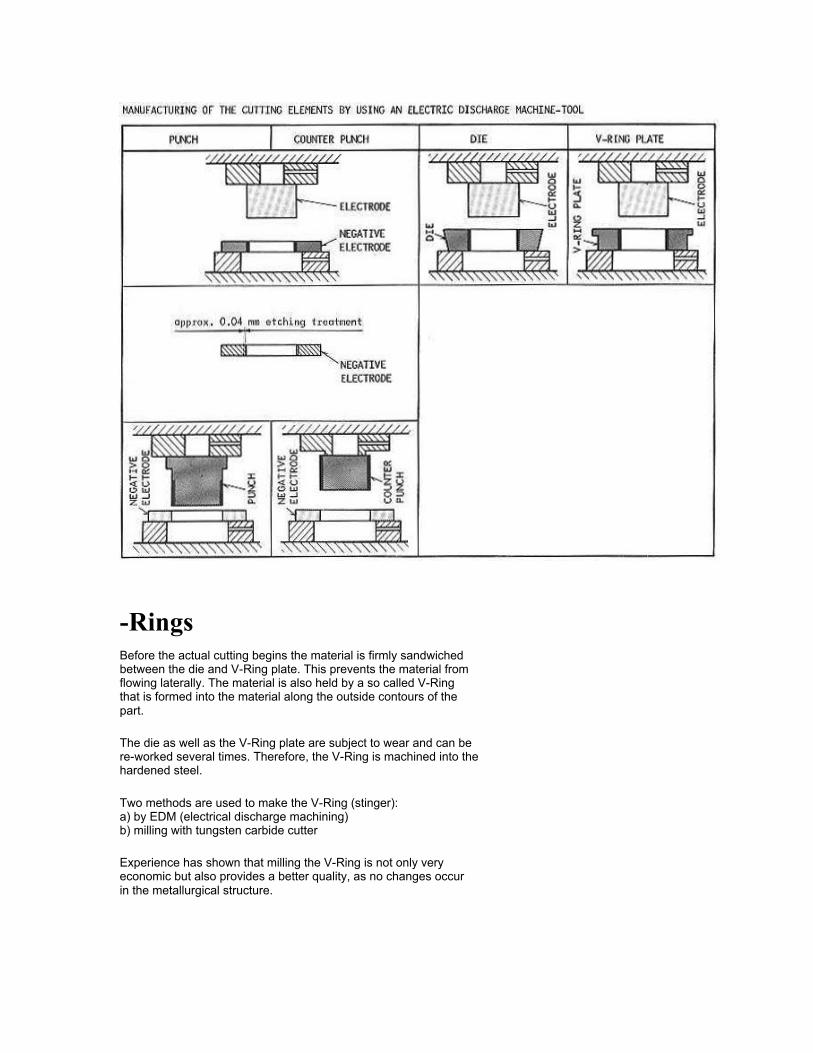
-Rings Before the actual cutting begins the material is firmly sandwiched between the die and V-Ring plate. This prevents the material from flowing laterally. The material is also held by a so called V-Ring that is formed into the material along the outside contours of the part.
The die as well as the V-Ring plate are subject to wear and can be re-worked several times. Therefore, the V-Ring is machined into the hardened steel.
Two methods are used to make the V-Ring (stinger): a) by EDM (electrical discharge machining) b) milling with tungsten carbide cutter
Experience has shown that milling the V-Ring is not only very economic but also provides a better quality, as no changes occur in the metallurgical structure.
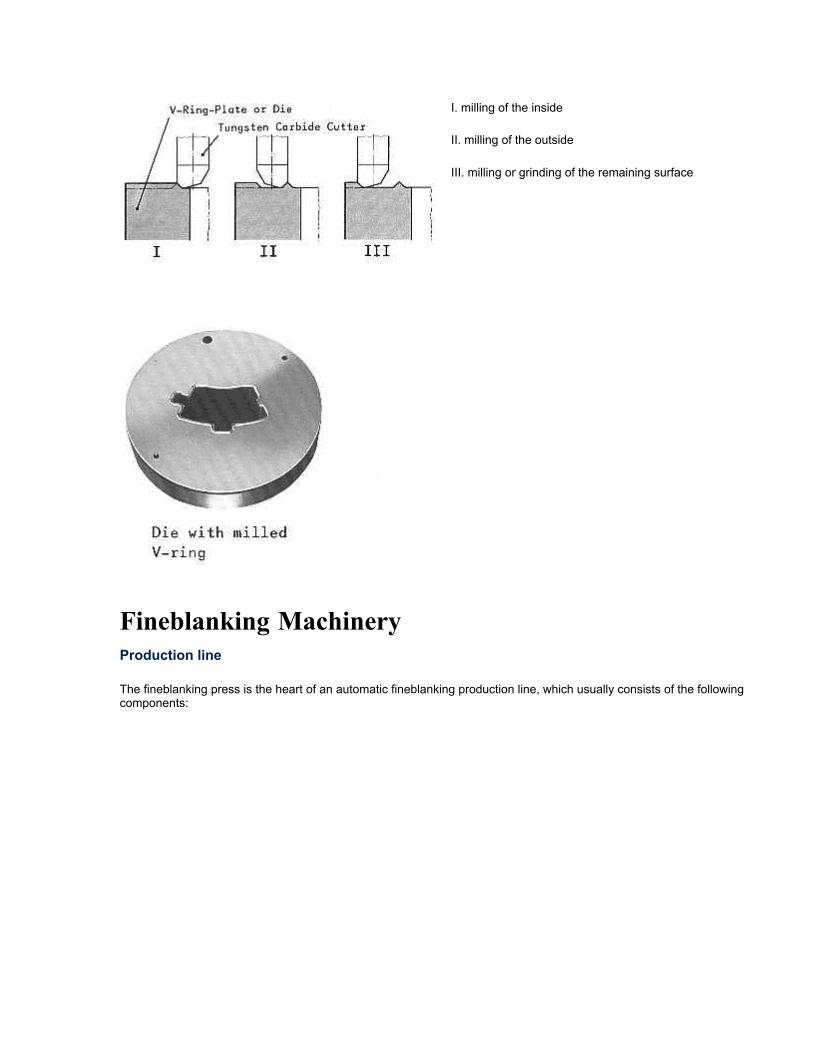
I. milling of the inside
II. milling of the outside
III. milling or grinding of the remaining surface
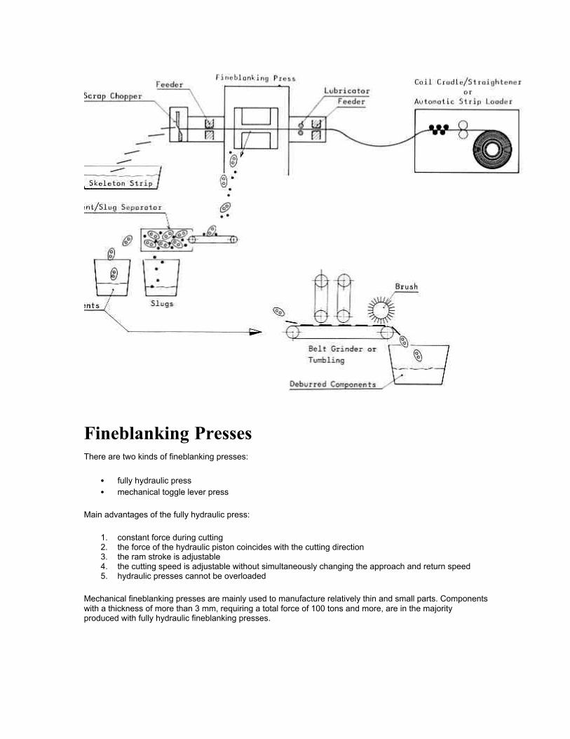
Fineblanking Machinery Production line
The fineblanking press is the heart of an automatic fineblanking production line, which usually consists of the following components:
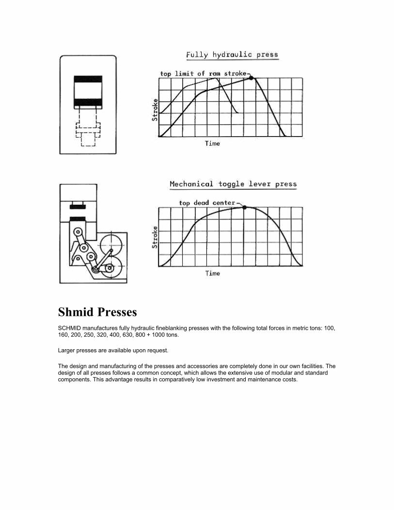
Fineblanking Presses There are two kinds of fineblanking presses:
• fully hydraulic press • mechanical toggle lever press
Main advantages of the fully hydraulic press:
1. constant force during cutting 2. the force of the hydraulic piston coincides with the cutting direction 3. the ram stroke is adjustable 4. the cutting speed is adjustable without simultaneously changing the approach and return speed 5. hydraulic presses cannot be overloaded
Mechanical fineblanking presses are mainly used to manufacture relatively thin and small parts. Components with a thickness of more than 3 mm, requiring a total force of 100 tons and more, are in the majority produced with fully hydraulic fineblanking presses.
Shmid Presses SCHMID manufactures fully hydraulic fineblanking presses with the following total forces in metric tons: 100, 160, 200, 250, 320, 400, 630, 800 + 1000 tons.
Larger presses are available upon request.
The design and manufacturing of the presses and accessories are completely done in our own facilities. The design of all presses follows a common concept, which allows the extensive use of modular and standard components. This advantage results in comparatively low investment and maintenance costs.
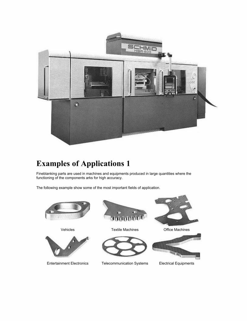
Examples of Applications 1 Fineblanking parts are used in machines and equipments produced in large quantities where the functioning of the components arks for high accuracy.
The following example show some of the most important fields of application.
Vehicles Textile Machines Office Machines
Entertainment Electronics Telecommunication Systems Electrical Equipments
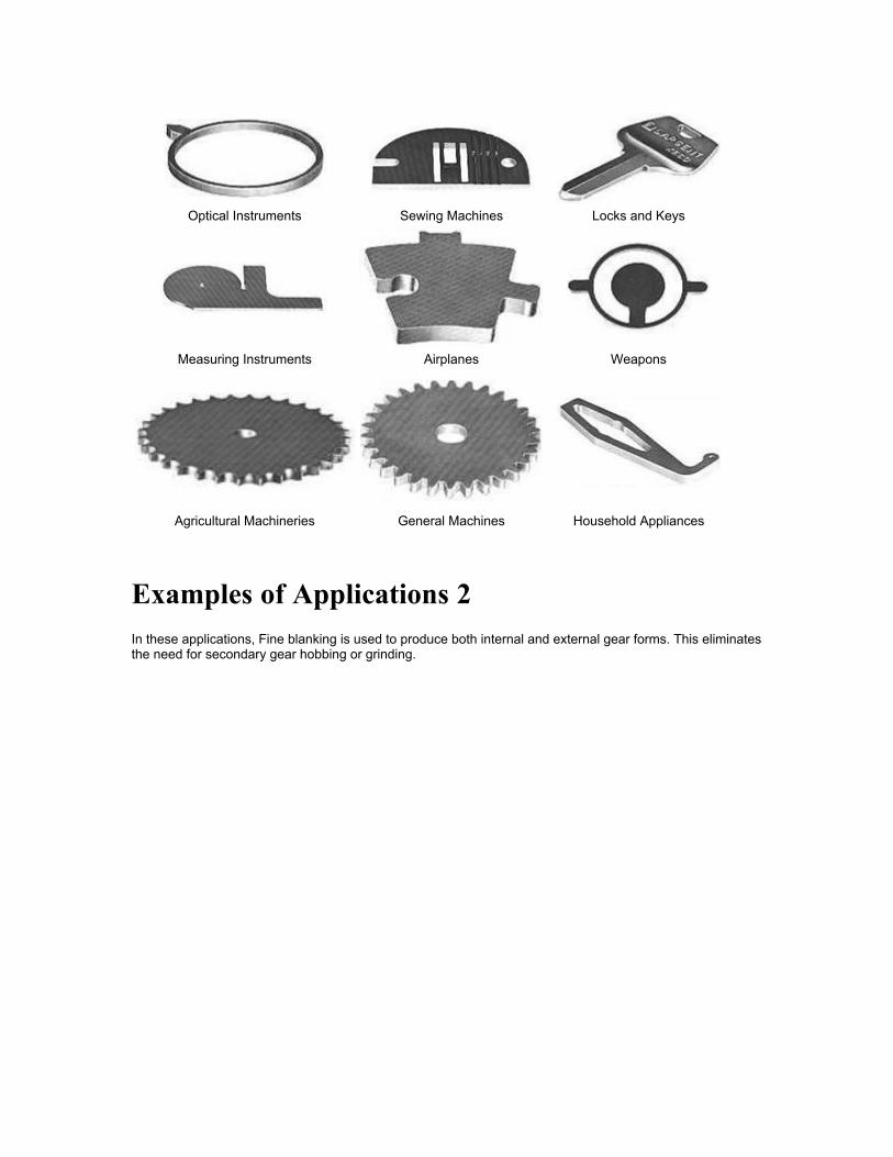
Optical Instruments Sewing Machines Locks and Keys
Measuring Instruments Airplanes Weapons
Agricultural Machineries General Machines Household Appliances
Examples of Applications 2 In these applications, Fine blanking is used to produce both internal and external gear forms. This eliminates the need for secondary gear hobbing or grinding.
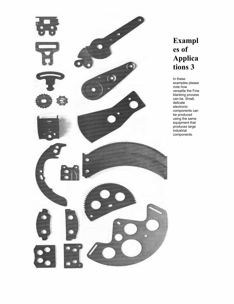
Examples of Applications 3 In these examples please note how versatile the Fine blanking process can be. Small, delicate electronic components can be produced using the same equipment that produces large industrial components.
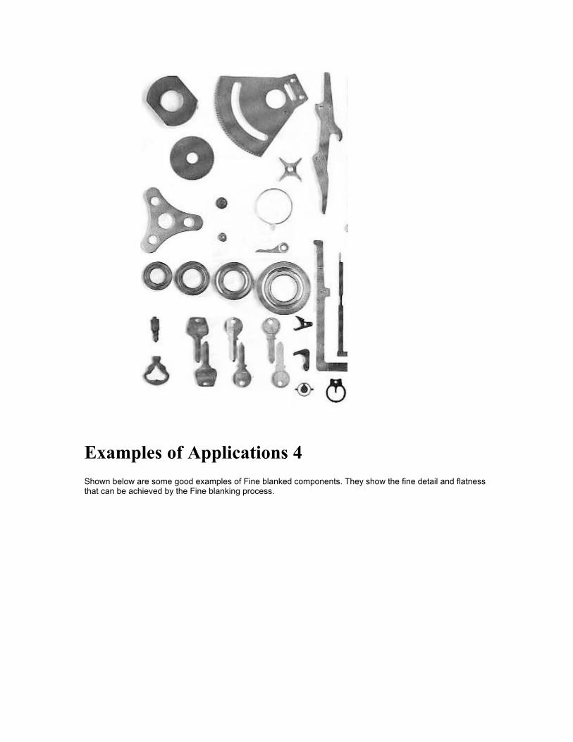
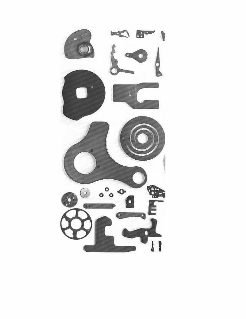
Examples of Applications 4 Shown below are some good examples of Fine blanked components. They show the fine detail and flatness that can be achieved by the Fine blanking process.
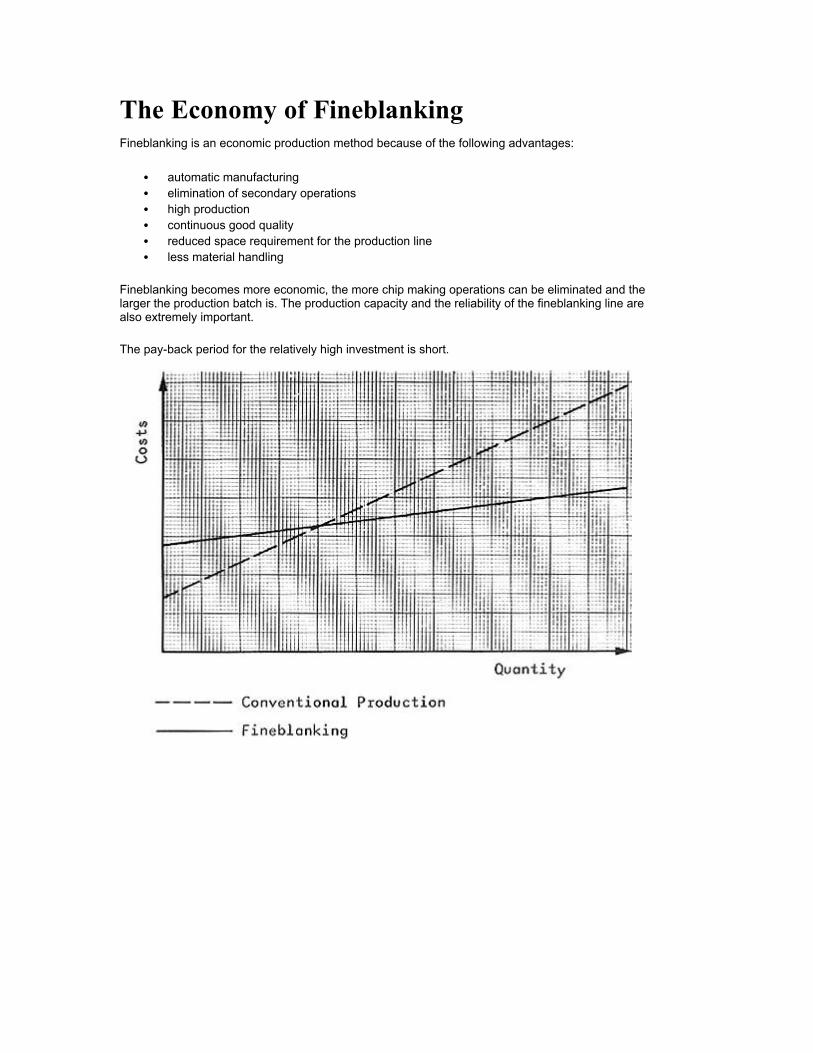
The Economy of Fineblanking Fineblanking is an economic production method because of the following advantages:
• automatic manufacturing • elimination of secondary operations • high production • continuous good quality • reduced space requirement for the production line • less material handling
Fineblanking becomes more economic, the more chip making operations can be eliminated and the larger the production batch is. The production capacity and the reliability of the fineblanking line are also extremely important.
The pay-back period for the relatively high investment is short.
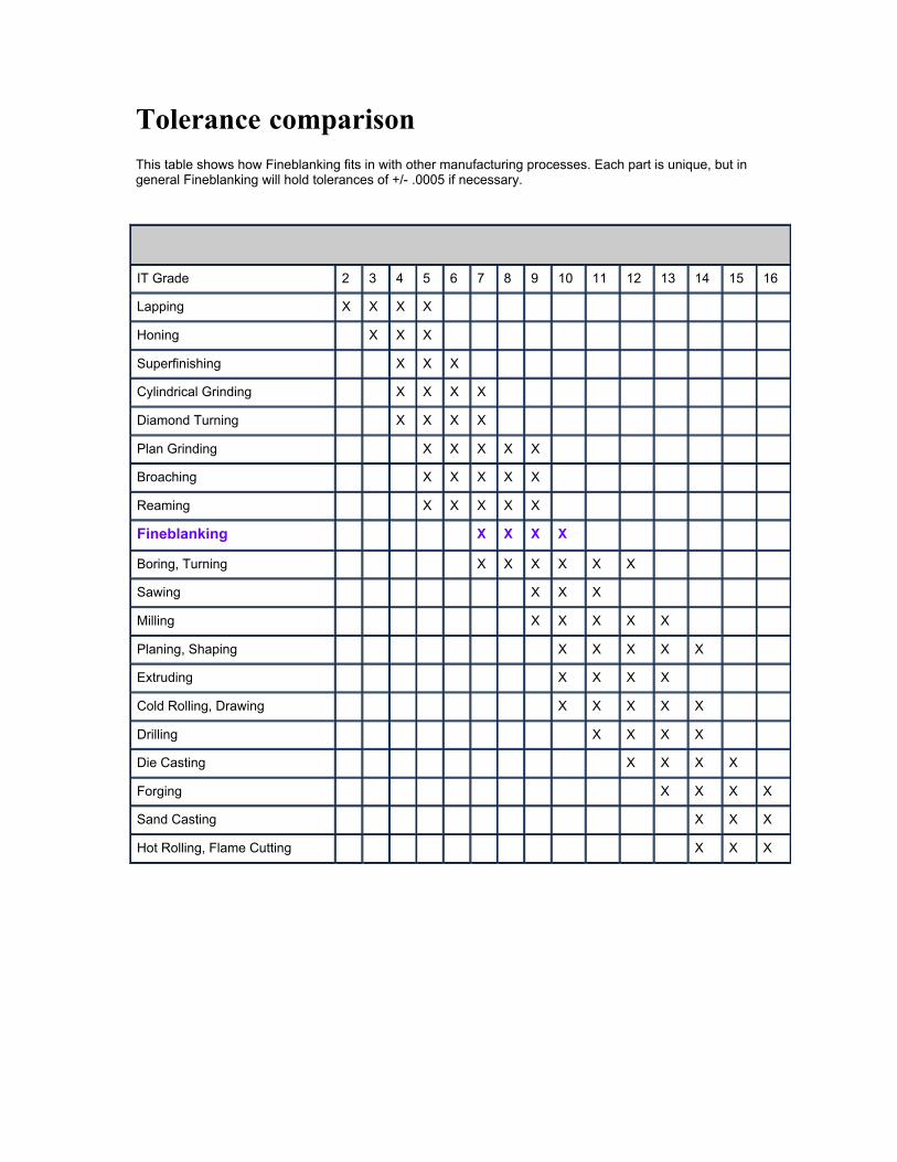
Tolerance comparison
This table shows how Fineblanking fits in with other manufacturing processes. Each part is unique, but in general Fineblanking will hold tolerances of +/- .0005 if necessary.
Machining Processes Associated with ISO IT Tolerance Grade
<-------------------------
most accurate------------------- least accurate
-------------------------- >
IT Grade
2
3
4
5
6
7
8
9
10
11
12
13
14
15
16
Lapping
X
X
X
X
Honing
X
X
X
Superfinishing
X
X
X
Cylindrical Grinding
X
X
X
X
Diamond Turning
X
X
X
X
Plan Grinding
X
X
X
X
X
Broaching
X
X
X
X
X
Reaming
X
X
X
X
X
Fineblanking
X
X
X
X
Boring, Turning
X
X
X
X
X
X
Sawing
X
X
X
Milling
X
X
X
X
X
Planing, Shaping
X
X
X
X
X
Extruding
X
X
X
X
Cold Rolling, Drawing
X
X
X
X
X
Drilling
X
X
X
X
Die Casting
X
X
X
X
Forging
X
X
X
X
Sand Casting
X
X
X
Hot Rolling, Flame Cutting
X
X
X