Embed Size (px)
Citation preview

Journal of Materials Processing Technology, 33 ( 1992 ) 331-345 331 Elsevier
Design study of the geometry of a punching/ blanking tool
U.P. Singh
Department of Mechanical and Industrial Engineering, University of Ulster, Jordanstown, UK
A.H. Streppel and H.J.J. Kals Department of Mechanical Engineering, Twente University, Enschede, Netherlands
Industrial Summary
The cost of tooling in sheet metal industries contributes a considerable part to the overall cost of manufacturing a component. It is therefore imperative to keep down this cost by ensuring that the tool works for a long period in production without interruption. One way of achieving this objective is to reduce the stress on the tool during punching/blanking.
This paper deals with the study of this problem by using the finite-element technique. 3-D finite-element models of various type of punching/blanking tools have been developed, these models enabling the analysis of the effects of variations in tool geometry on the punching/blanking force and on the deformation of the punch, a parameter highly relevant to the assessment of tool per- formance in terms of the accuracy of the manufactured components. The model caters also for variation in the characteristics of the tool material, in the sense that a highly wear-resistant tool is normally composed of carbide tips around its cutting profile. Computed results by FE models are checked against design standards by American Society of Manufacturing Engineers (SME). Some suggestions are offered as to how the efficiency of a punching/blanking tool can be improved.
I. Introduction
Experience shows that cost of tooling in sheet metal industries contributes a substantial part to the overall cost of manufacturing a component, so that it is essential to keep down this cost by ensuring that the tool works for a long period without interruption. To achieve this objective a production engineer has the following options: (i) to minimize the deflection of a forming machine tool to be employed in the punching/blanking operation; or (ii) to minimize the deflection of the die-set to be employed on the forming machine; or (iii) to reduce the stress on the punching/blanking tool; or (iv) to effect a combina- tion of the foregoing three options. The options in items (i) and (ii) have been
Correspondence to: U.P. Singh, Department of Mechanical and Industrial Engineering, Univer- sity of Ulster, Jordanstown, UK.
0924-0136/92/$05.00 © 1992 Elsevier Science Publishers B.V. All rights reserved.
332
dealt with at length in Refs. [1-6], whilst the option in item (iii) has, so far, been dealt with by experimental means only [7,8 ]. A survey of the literature suggests that no theoretical or precise empirical relationship is available that can aid tool users in the rational selection of tool parameters resulting in min- imum distortion of the tool in operation, thereby improving the tool life and enhancing the quality of the product.
To reduce the stress on the tool and thus enable thicker or more resistant stock to be punched on the same press or to permit the use of lower-rated presses, the employment of a punch or die with ground relief on its face is a common practice. It is reported [ 7,8 ] that punching/blanking forces vary with various amounts of shear relief on the tool face. However, there is little infor- mation available to tool users as to how the amount of shear relief has to be chosen in practice in relation to the punching force required for a given product.
This paper deals with the design analysis of various types of punches with special attention to their cutting profiles, using the finite-element technique. Results obtained by the finite-element analysis of the punches enable the drawing of specific conclusions with regard to the selection of punches in prac- tice for minimum distortion of the punch and reduced stress on the punch.
2 . M o d e l l i n g o f t h e p u n c h
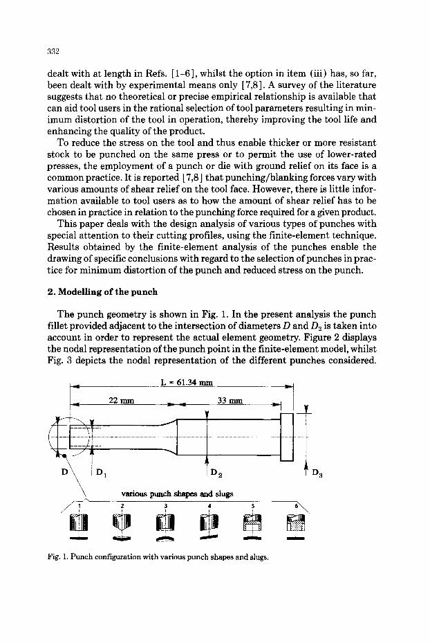
The punch geometry is shown in Fig. 1. In the present analysis the punch fillet provided adjacent to the intersection of diameters D and D2 is taken into account in order to represent the actual element geometry. Figure 2 displays the nodal representation of the punch point in the finite-element model, whilst Fig. 3 depicts the nodal representation of the different punches considered.
L = 61.34 mrn
~ 2 2 n ~ n , 33 m m ~
Y
L
D2
various punch shapes and slugs
! ! ! ! !
Fig. 1. Punch configuration with various punch shapes and slugs.
D 3

333
The nodal coordinates of the punch points shown in Fig. 2 are presented in Table 1. For every element defined by the coordinates in Table 1 at the O- surface there will be a symmetrically placed element in the second, the third and the fourth quadrant, in such way that
#
X o ~ - - X o -~-- - - X o ---- X o
y'o = y o = - - y o = - - y o (1) #
Z o ---- Z o ---~ Z o ---- Z o
It is convenient to define a parallel surface called the A-surface that is placed at a distance S from the O-surface along the Z-axis (Figs. 4 (a) and 4 (b) ). The points on this surface are obtained by giving an axial motion to those on the O-surface. The point (Xa, Y,, Z~) on the A-surface corresponding to the point on the O-surface will be such that
Y, = Yo 0 (2) Za Zo 1 S~
Equation 2 is used to generate the nodal-point data for the finite-elements models of the punches.
/1' 1 °
D 1
D
Fig. 2. Nodal r epresen ta t ion of the geometry of the p u n c h point .
334
punch 2 punch 3
punch 1 6
punch 4 punch 5
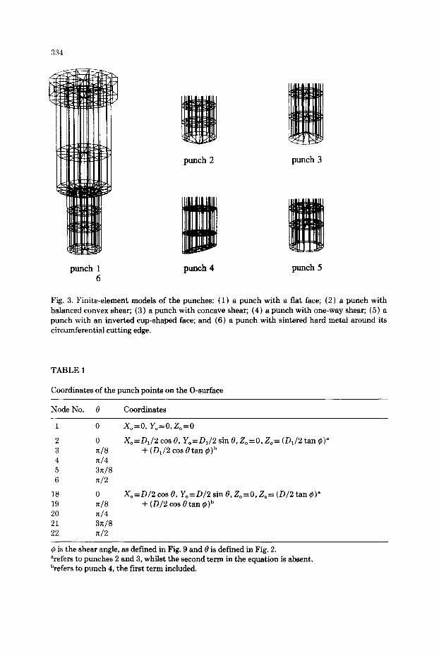
Fig. 3. Finite-element models of the punches: (1) a punch with a flat face; (2) a punch with balanced convex shear; (3) a punch with concave shear; (4) a punch with one-way shear; (5) a punch with an inverted cup-shaped face; and (6) a punch with sintered hard metal around its circumferential cutting edge.
TABLE1
CooMinatesof thepunchpoin tsontheO-surhce
Node No. 0 Coordinates
1 0
2 0 3 ~/8 4 X/4 5 3n/8 6 ~/2
18 0 19 ~/8 20 n/4 21 3n/8 22 n/2
Xo=O, Yo=O, Zo=O
Xo=D1/2 cos 0, Yo=D1/2 sin 0, Zo=0, Zo= (D1/2 tan ¢)a + (D1/2 cos 0tan ¢)b
Xo=D/2 cos O, Yo=D/2 sin O, Zo=O, Zo= (D/2 tan ~)~ + (D/2 cos 0 tan ~)b
¢ is the shear angle, as defined in Fig. 9 and 0 is defined in Fig. 2. arefers to punches 2 and 3, whilst the second term in the equation is absent. brefers to punch 4, the first term included.

A
O
i
O
335
a b Fig. 4. Brick configuration and an 8-node element for punch 1,6 (a) and punch 2 (b).
Figure 4 shows the elements of the first quadrant and the corresponding brick forms in the second quadrant. Similar types of elements with their sym- metrical counterparts are stacked up to the height of the punch in building the finite-element model for the punch.
The procedure employed to obtain the deformation of the punch is illus- trated in Fig. 5, where the material properties, the boundary conditions and the loading conditions need to be supplied as an input to the model. A view of distorted punches 1 and 4 is presented in Fig. 6.
2.1. Boundary condition The top plate of the die-set containing the punch along with the upper head
of the press tends to deflect as the thrust is applied to the punch [6]. Conse- quently, the top plate of the die-set carrying the punch follows the lateral movements of the top head of the press. To account for these movements, the nodal points on the top surface of the punch should be given a prescribed dis- placement equivalent to the amount of deflection of the die-set at the punch- head section. As the prime objective of this paper is to analyse the rigidity characteristics of a punch with various design features, it is perfectly justified to set the top surface of the punch fixed. Thus the boundary condition corre- sponds to simply setting those nodal points on the top surface to zero (see Table 2 ).
2.2. Punch load For the analysis of punch deformation, a static load corresponding to the
punching load is defined. Young's modulus and Poisson's ratio for the punch material are to be provided. When assuming that the mechanics of punching is based on pure shearing, the instantaneous punching force Fp (see Fig. 7) is as given in Ref. [6]:

336
finite element
approxim- mation T
load & boundary] conditions
calculation of displacement
& stresses
element ~:~ data
type
\
solution of load-deflection from equation
Fig. 5. Finite-element procedure.
@@ A ~ calculation of element
stiffness matrices N /
combination ¢:~ of element
properties
/
/
punch 1
Fig. 6. View of distorted punches.
punch 4

TABLE 2
Set prescribed displacements of the nodes at the top surface of the punch
337
Node No. Prescribed displacement (mm)
U V W
232 0.0 0.0 0.0 281 0.0 0.0 0.0 285 0.0 0.0 0.0 289 0.0 0.0 0.0 293 0.0 0.0 0.0
Z D/2
Fig. 7. Load on the cutting edge of the punch.
F , = ~ux/f3 D h C [k In (ho/h) ]n
and hence the m a x i m u m force by
F p ~ = ~ u x / ~ D ho C [n/e] n k n
w h e n neglect ing the inf luence of fr ic t ion.
(3)
(4)
338
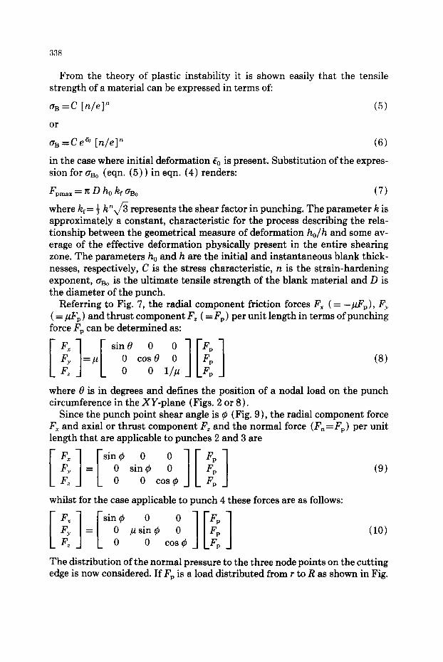
From the theory of plastic instability it is shown easily that the tensile strength of a material can be expressed in terms of:
as =C [n/e]" (5)
or
aB=ee e° [n/e]" (6)
in the case where initial deformation Q is present. Substitution of the expres- sion for aso (eqn. (5)) in eqn. (4) renders:
Fpmax = ~ D ho k~ •Bo (7)
where kf= ~ k"v/3 represents the shear factor in punching. The parameter k is approximately a constant, characteristic for the process describing the rela- tionship between the geometrical measure of deformation ho/h and some av- erage of the effective deformation physically present in the entire shearing zone. The parameters ho and h are the initial and instantaneous blank thick- nesses, respectively, C is the stress characteristic, n is the strain-hardening exponent, aBo is the ultimate tensile strength of the blank material and D is the diameter of the punch.
Referring to Fig. 7, the radial component friction forces Fx (= - / ~ p ) , Fy ( = p~,) and thrust component Fz ( = Fp ) per unit length in terms of punching force F, can be determined as:
Esin° ° °lEVI F~ =/~ 0 cosO 0 Fp Fz 0 0 1/~ Fp
(8)
where 0 is in degrees and defines the position of a nodal load on the punch circumference in the XY-plane (Figs. 2 or 8).
Since the punch point shear angle is ~ (Fig. 9), the radial component force Fx and axial or thrust component Fz and the normal force (Fn=Fp) per unit length that are applicable to punches 2 and 3 are
[Fx lFy [SioO n O ] [ 1 siO¢ 0 F, = Fp (9)
Fz 0 cos~ F,
whilst for the case applicable to punch 4 these forces are as follows:
I o o 1 F~ = p sin ~ 0 Fp Fz 0 cos 0 F,
(10)
The distribution of the normal pressure to the three node points on the cutting edge is now considered. If F, is a load distributed from r to R as shown in Fig.

v
X
339
Fig. 8. Radial deformation.
~ z
x /Fndr Fzdr
Fig. 9. Load on the cutting edge of a punch of shear angle ~.
Fig. 10. Distribution of load.
10, the three nodal loads in the direction of Fp for an 8-node element are given by:
F~ =F~R - 0 -½ _ I Fp3 t_~ 0 ¼ lEi:l (11)
where ~= r/R. Loads Fx, Fy and Fz have to be distributed to the nodes on the cutting edge according to eqn. (11).

340
TABLE 3
Nodal loads on the cut t ing edge surface
Punch profile Shear angle Node No. Force (N) No. ¢ (degrees)
F~ F~ F~
1 ,5 ,6 0 1 248 - 2 4 8 2482 10 1003 - 1003 10027 26 3266 - 3 2 6 6 32656
2,3 22.5 1 948 - 9 4 8 2293 10 3837 - 3 8 3 7 9264 26 12497 - 1 2 4 9 7 30170
4 22.5 1 12497 - 1250 30170 10 3837 - 3 8 4 9264 26 948 - 9 5 2293
For numerical computations, the following punch and blank geometry is used: punch diameter D = 12 mm; blank thickness ho = 6 ram; ultimate tensile strength of the blank material aBo = 520 N/ram2; k = 2.92 (after eqn. (7) ); strain-hard- ening exponent n = 0.264; b = R - r = (2-3.5) J as in Ref. [ 8 ]; the clearance be- tween die and punch J = 0.1 ho; and the coefficient of friction/1 = 0.10.
For the steel, Young's modulus is 210 GPa and Poisson's ratio is 0.3; whilst for the hard metal these quantities are 500 GPa and 0.22, respectively.
Substitution of the pressure distribution given by eqn. ( 11 ) into eqns. (8)- (10) results in the nodal forces at 1, 10, and 26 (Fig. 2) for ~=0.666, as shown in Table 3. The model of each of the punches 1, 2, 3, 5 and 6 consists of 184 linear hexadredronal elements whilst the model of punch 4 is composed of 183 linear hexahedral elements.
3. Punch deformation
The nodal-point deformations of the punch are represented by u, v and w which are the x, y and z component displacements, respectively. The displace- ment of the outermost node, for example node number 25, of the punch is of interest as this is related directly to the performance of the tool, the radial displacement AR representing the variation in punch size and position whilst cutting. Referring to Fig. 8, AR is given precisely by
AR= [ (R cos 0+u)2+ (R sin 0 - v ) 2] 1/2-R (12)
4. Results
Before carrying out an investigation into the design parameters of a punch,

341
an assessment of the reliability of the finite-element model is needed. For the FE model to be valid, the model results have to be compared to either experi- mental results or to experimental data established by others. In this case the FE force model which has a direct relationship with the tool deformation, is compared to and checked against the experimental force data produced by the American Society of Manufacturing Engineers (SME) [ 7 ] and by Ramanov- sky [S].
4. I. Evaluation with respect to punch load In Fig. 11, results are shown for the punch load as a function of the shear
angle, ¢~, from which it is seen that punch load Fz reduces gradually as the shear angle (or the shear height) increases, whilst punch loads Fx and Fy rises sharply with increasing shear angle. Comparison of results between the FE force model and SME displays a fair correlation and thus establishes the validity of the finite-element model. The results also highlight that the effect of punch loads Fx or Fy or a combination of both could be severe on the performance of a tool if a punch with one-way shear, for example punch 4, is used (Fig. 12).
4.2. Tool design considerations From the point of view of machine-tool users, tooling aspects of production
such as tool failure and deterioration in the dimensional accuracy of a manu- factured component, are particularly important. The performance of a tool will be considerably enhanced if a punch of particular design (Fig. 1 ) is employed. Consequently, the design parameters of a punch such as the shear relief angle
1oo
70 " ~ t ~ 60. + . 1 / .
50.
3o- ~ . ~ + + F~,Fy
20 . ~ - A A Fz
10 ~ - (~ e,xpedmmtt74]
0 o 7'.5 1'5 22.5 30 37.5 4~5
, ~ > shear angle 4~ [degree]
Fig. 11. Punch load versus shear angle ~o.

342
350 0 30O
250 ~ 2~
150 .~ 100 ~ 50 ~ o • ~ -50 ~ -100
-150 -200
l ! -250 -300 -350 -400
~ i!i ~ i ~
i
3
0 \ i.5 i5 27~.5 - - 3~0 3+.5 4'5
r -
8
l ~ _ _ ~ shear angle • [degree]
Fig. 12. Radial deflection versus shear angle ~.
on the face of the punch, the shape of the cutting profile and tool material characteristics, are of interest.
Figure 13 shows the radial stiffness of various types of tools. The shear angle, 0, for punches 2, 3 and 4 is 22.5 ° whilst for punches 1, 5 and 6, 0 = 0 °. Com- parison of the results shows the measure of improvement in tool performance if punch 2, with balanced convex shear, is employed. The results suggest that the use of punch 2 is most desirable if high dimensional accuracy of a compo- nent is required, and a thicker or more resistant blank material is to be punched on the same press.
Figure 14 depicts the axial stiffness of various types of punches for the shear angles as given above, comparison of the results demonstrating the superiority of punch 6 over all other types of punches. The results suggest that the use of punch 6, with sintered hard metal around its circumferential cutting edge, may be quite desirable if the punch encounters no eccentric load (see Fig. 13 ).
The relationship for the radial deflection, AR, of punches 2, 3 and 4 as a function of shear angle, ~, is illustrated in Fig. 12. Analysis of the results re- veals that a shear angle of between 17°-22 ° results in a minimum radial de- formation for the punches 2 and 3, which implies that punches 2 and 3 with shear angle ~-~ 20 ° can be employed in practice safely in order to satisfy the tolerance criterion [7-9 ] for manufactured components made of a range of materials such as aluminium alloys, brass, cold-rolled steel and stainless steel. The radial deflection of punch 4 deteriorates with increasing shear angle. The

i 50-
0
30
d • ~ 20
l°
,i
1 2 3
H u n Fig. 13. Radial stiffness versus punch type.
Punches 2, 3 and 4 with shear angle #p - 22.5 °
o ~
5' 6
, i ] ~ punch ~
360
---.. 320
28O
200
l"!t oL
he)
eq
il i/il 1
i
Punches 2, 3 and 4 with shear angle 4) ffi 22.5 °
:: '!i ¸̧ :ii~: 1 ~i ~!~ '~! '~: I
!I ii!il !iiii q 2 !
u i
Fig. 14. Axial stiffness versus
('4
' ! ! i I
3 !
4 !
N p u n c h type.
i%'i,i] :!ii!
i t !ili~ ~
5 6
i i punch vype
343
344
l 4OO
300
200 ~
0 -
-100
-200
-300 -
-4O0
0
1 I
i
2
• ¢ = 22.5 ° i
5
i
A i
i - - I I I
0.1 0.2 0.3 0.4
E ~=> ratio 7_gL
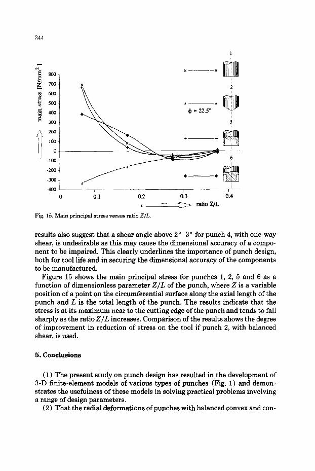
Fig. 15. Main pr incipal s t ress versus ratio Z/L.
results also suggest that a shear angle above 2 °-3 ° for punch 4, with one-way shear, is undesirable as this may cause the dimensional accuracy of a compo- nent to be impaired. This clearly underlines the importance of punch design, both for tool life and in securing the dimensional accuracy of the components to be manufactured.
Figure 15 shows the main principal stress for punches 1, 2, 5 and 6 as a function of dimensionless parameter Z/L of the punch, where Z is a variable position of a point on the circumferential surface along the axial length of the punch and L is the total length of the punch. The results indicate that the stress is at its maximum near to the cutting edge of the punch and tends to fall sharply as the ratio Z/L increases. Comparison of the results shows the degree of improvement in reduction of stress on the tool if punch 2, with balanced shear, is used.
5. Conclus ions
(1) The present study on punch design has resulted in the development of 3-D finite-element models of various types of punches (Fig. 1) and demon- strates the usefulness of these models in solving practical problems involving a range of design parameters.
(2) That the radial deformations of punches with balanced convex and con-

345
cave shear have a minimum value within the shear angle range of 17°-22 ° suggests that a shear angle of 20 ° can be proposed safely for practical purposes.
(3) That amongst the rigidity characteristics evaluated for all types of punches, the punch with balanced convex shear, 2, shows the best performance (Figs. 13 and 15), suggests that this type of punch can reasonably be recom- mended in practice in order to reduce the stress on the tool and thus to enable thicker or more resistant stock to be punched on the same press or to permit the use of a lower-rated press.
(4) Since the inclusion of eccentricity due to assymmetric load on the press is an important factor in the punching/blanking process [6], the choice of punch 2, with balanced convex shear, against punch 6, with sintered hard metal around its circumferential cutting edge, is obvious (Fig. 11 ), despite the axial stiffness of punch 6 having a substantially greater competitive edge than punch 2.
Acknowledgements
The authors wish to express their sincere thanks to Mr. J.H. Postma for his assistance in providing the graphic facility, Ir. F.J.A.M. van Houten, Dr. A.H. van 't Erve and Ing. G.W. Bloemendaal for the computing facility and Miss. Bruinink for typing the manuscript.
References
I U.P. Singh, P,C. Veenstra and J.A. Ramaekers, Numerical analysis of the distortional behav- iour of a hydraulic press, Ann. CIRP, 16 (1) (1977) 119.
2 U.P. Singh, Design analysis of a single column pressframe, ASME Trans., J. Vibr. Acoust. Stress Reliab., 106 (October 1984) 508-516.
3 U.P. Singh, R. Wilson and S. Hinduja, Computer aided study of a single column hydraulic press, Proc. 25th Int. Machine Tool Design and Research Conf., Birmingham, April, 1985, Macmillan, London, pp. 389-395.
4 J.A. Hijink and A.C.H. vander Wolf, On the design of die-sets, Ann. CIRP, 24 (1975) 127. 5 U.P. Singh and P.P. Miller, Computer aided design of a die-set, Proc. 2nd Conf. of the Irish
Manufacturing Committee, Jordanstown, September, 1985, pp. 637-651. 6 U.P. Singh, H.J.J. Kals and A.H. Streppel, Computer aided design study of a die-set for punch-
ing/blanking, Proc. 28th Int. Machine Tool Design and Research Conf., Manchester, April, 1990, Macmillan, London, pp. 379-386.
7 Tools and Manufacturing Engineers Handbook, 3rd edn., McGraw-Hill, New York, 1976, pp. 4.5-4.12.
8 N.P. Ramanovsky, Hand Book on Die Design, 5th edn., Mashinostroenia, Leningrad, 1971, pp. 26-30.
9 Donald F. Early, Press alignment, Tool Manuf. Eng., 42 (6) (1962).