Embed Size (px)
Citation preview
2011
American University of Beirut Faculty of Engineering and Architecture
[FINAL YEAR PROJECT-MECH 502 : THE LEBANESE LINEAR PLASMA DEVICE]
Ralph Ghazal 200800747 Nareg Oughourlian 200800736
Michel Haddad 200800801 Mickael Haddad 200800532
1 | P a g e
Acknowledgments:
There are several people to whom we must express our heartfelt gratitude for their assistance in so
many ways as we endeavored to realize this project.
We are so grateful for our conscientious and meticulous advisors, Dr. Marwan Darwish and Dr. Ghassan
Antar, who guided us through every step of the way and who gave invaluable advice that enabled us to
enhance this report at every stage.
We thank our professors who shaped our lives and minds and made us the engineers we are today.
We thank staff personnel at the AUB physical plant, who provided us with much needed advice and
contact information without which we could not have realized our design.
And most of all, we thank our parents who valued our education above all else. We could not have done
it without their unquestionable support.
2 | P a g e
Table of Contents Acknowledgments: ....................................................................................................................................... 1
List of figures: ................................................................................................................................................ 3
Introduction: ................................................................................................................................................. 5
Abstract: ........................................................................................................................................................ 6
Project outline:.............................................................................................................................................. 7
Part 1: Bill of materials: ............................................................................................................................. 7
Part 2: Identification of the missing material: .......................................................................................... 9
Part 3: Support structure .......................................................................................................................... 9
Stress analysis on critical points. ................................................................................................................ 11
Introducing the stress analysis:............................................................................................................... 12
Free body diagram of the system as a whole. ........................................................................................ 13
2-dimensional analysis of the system stresses. .................................................................................. 13
Stress analysis at point A: ................................................................................................................... 15
Stress analysis at point B: Normal stress on the leg ........................................................................... 21
Stress analysis at point C: Middle Plate Calculation ........................................................................... 22
Final Design ............................................................................................................................................. 24
Manufacturing ........................................................................................................................................ 26
Pumping system .......................................................................................................................................... 27
The pumping system: .............................................................................................................................. 27
The vacuum process: .......................................................................................................................... 27
Choice of Pumps: ................................................................................................................................ 28
Complete pumping System Design: ........................................................................................................ 29
First draft:............................................................................................................................................ 29
Updated draft: .................................................................................................................................... 30
Part 5: the Coil Box .................................................................................................................................. 33
Appendix A .................................................................................................................................................. 36
Part 1) “Ethical and professional responsibilities” .................................................................................. 36
Part 2) “Understanding in a social context”............................................................................................ 37
Part 3) “Project as a Business Model” .................................................................................................... 38
Appendix B .................................................................................................................................................. 39
3 | P a g e
List of figures: Figure 1 Nuclear Fusion explained ................................................................................................................ 5
Figure 2: assembly 1...................................................................................................................................... 8
Figure 3: assembly 2...................................................................................................................................... 8
Figure 4: assembly 3...................................................................................................................................... 8
Figure 5: rendering of support structure .................................................................................................... 10
Figure 6: Clamp that allows movement found on common desk ............................................................... 10
Figure 7: The design as drawn on PROE software ...................................................................................... 11
Figure 8: Side view of the support system .................................................................................................. 13
Figure 9: Upper view of the support ........................................................................................................... 13
Figure 10: I beam cross section ................................................................................................................... 14
Figure 11: FBD at point A ............................................................................................................................ 15
Figure 12: Side view of a single I beam ....................................................................................................... 16
Figure 13: Reaction forces of support ......................................................................................................... 16
Figure 14: Free body diagram ..................................................................................................................... 19
Figure 15: Shear diagram ............................................................................................................................ 19
Figure 16: Moment diagram ....................................................................................................................... 20
Figure 17: I beam cross section ................................................................................................................... 20
Figure 18: cross section 1 of the leg ........................................................................................................... 21
Figure 19: solid area of leg .......................................................................................................................... 21
Figure 20: Middle plate free body diagram ................................................................................................ 22
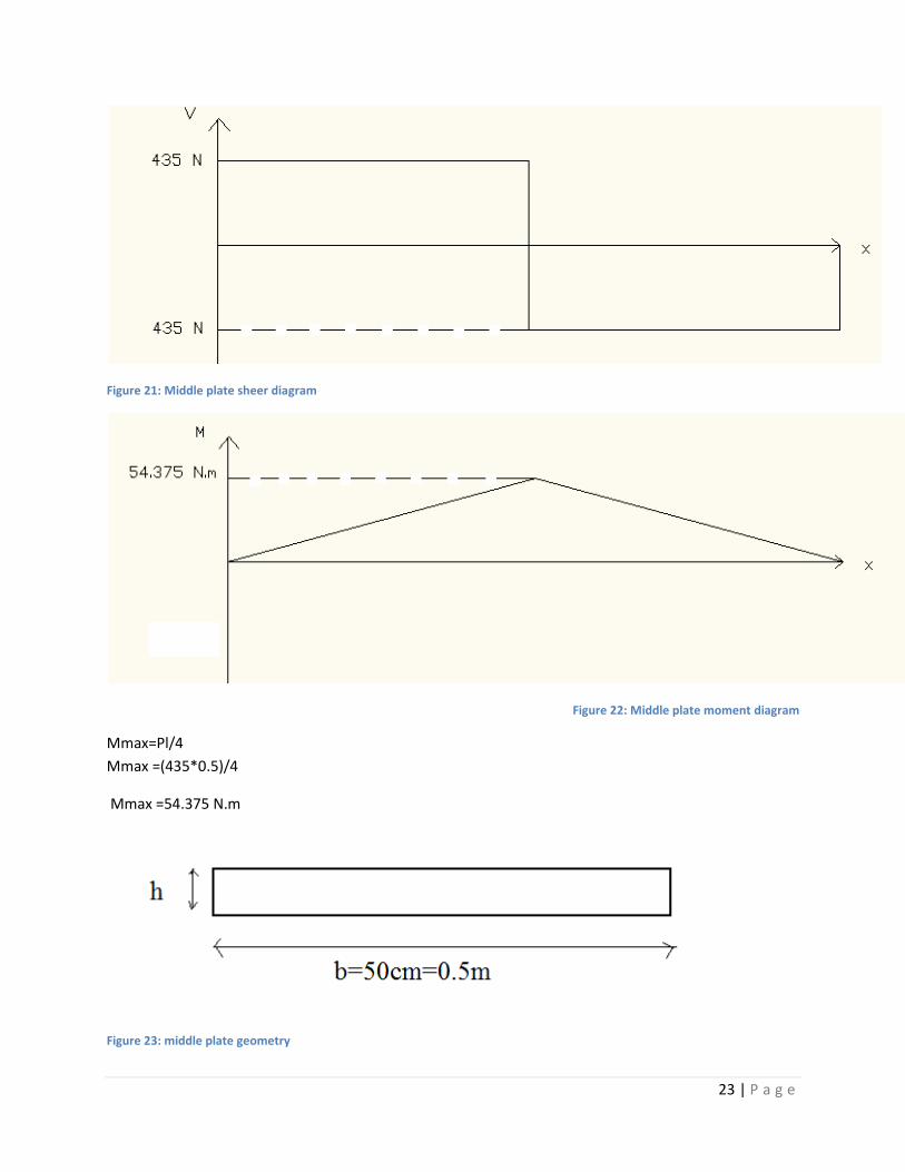
Figure 21: Middle plate sheer diagram ....................................................................................................... 23
Figure 22: Middle plate moment diagram .................................................................................................. 23
Figure 23: middle plate geometry ............................................................................................................... 23
Figure 24: Longitudinal base long ............................................................................................................... 24
Figure 25: Cross bar .................................................................................................................................... 24
Figure 26: I beam ........................................................................................................................................ 25
Figure 27: Square holder ............................................................................................................................. 25
Figure 28: Support leg ................................................................................................................................. 25
Figure 29: Transverse base long ................................................................................................................. 25
Figure 30: S holder ...................................................................................................................................... 26
Figure 31: Full assembly of the support system ......................................................................................... 26
Figure 32: Effect of intermolecular distance on Pressure........................................................................... 27
Figure 33: Flow Regime Boundaries............................................................................................................ 28
Figure 34: Turbo Pump ............................................................................................................................... 28
Figure 35: Vacuum Pumping System Preliminary Design ........................................................................... 29
Figure 36: Second draft of pumping system ............................................................................................... 30
Figure 37: third draft of pumping system ................................................................................................... 31
Figure 38: CF flange ..................................................................................................................................... 32
Figure 39: KF flange ..................................................................................................................................... 32
Figure 40: Coil Box ...................................................................................................................................... 33

4 | P a g e
Figure 41: Center plates designed to hold the coils in place ...................................................................... 34
Figure 42: Coil configuration, each three coil boxes will be supplied with one generator ........................ 34
5 | P a g e
Introduction: Nuclear fusion is nothing short than the holy grail of science. It promises to solve all our
environmental and energy related problems and provide us with an abundant fuel supply for
earth and beyond.
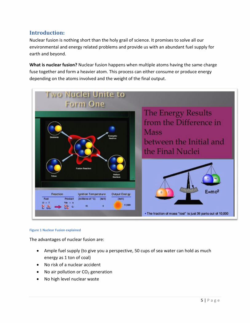
What is nuclear fusion? Nuclear fusion happens when multiple atoms having the same charge
fuse together and form a heavier atom. This process can either consume or produce energy
depending on the atoms involved and the weight of the final output.
Figure 1 Nuclear Fusion explained
The advantages of nuclear fusion are:
Ample fuel supply (to give you a perspective, 50 cups of sea water can hold as much
energy as 1 ton of coal)
No risk of a nuclear accident
No air pollution or CO2 generation
No high level nuclear waste
6 | P a g e
But the problem with nuclear fusion is in getting two atoms similarly charged close to each
other, because they will tend to repel each other due to their same charge. But once they
are close enough the nuclear force will take over and complete the fusion process.
The major obstacle in fusion technology is plasma turbulence that greatly reduces the
efficiency of the system and makes it energy consuming rather than producing.
AUB is undertaking the project of building the first Lebanese Linear Plasma Device (LLPD)
that will be used to study turbulence in the plasma and ways to optimize the process.
Abstract: The department of physics in collaboration with the faculty of engineering and architecture
is building the LLPD which is basically a cylinder like vacuum chamber where the plasma will
be created and the flow studied in order to simulate problems faced in the actual fusion
power plant.
This project is very important because it will allow AUB and Lebanon to partake in the global
effort for fusion development. And since the device will be unique in the region (including
Israel) and it will have unique characteristics worldwide, then it will further solidify AUB’s
role at the forefront of intellectual innovation and technological development.
The mechanical engineering team will handle:
The support structure
The pumping system (gas in, gas out)
The system assembly
The milestones of the project are:
Understand the problem: vacuum, support
Make CAD (or equivalent) drawing of the whole setup
Identify missing components
Design the pumping system
Design the support structure
Design the coil box
Assemble the system
7 | P a g e
Project outline: The project is mainly divided into three main parts each in its turn divided into sub-divisions.
Part 1: Bill of materials:
This part is where the team had to visit the plasma lab at the physics building at AUB campus to
identify the available parts for the system. Dr. Antar showed briefly how the system must be
assembled and the available parts and left the team to identify the possible arrangement and
realize the missing material to be ordered.
Table 1 in appendix B describes the parts of the pumping system. Table 2 in the appendix B
describes the needed gaskets for the system, stating them clearly. Those gaskets have their CAD
drawings online; we will obtain them after ordering the parts.
CAD drawings: are the professional drawings of the system that are required to proceed
This includes:
1- Drawing the system to be build using PRO-E software:
a- To accomplish this part, measures of all the parts have to be taken accurately
b- Some of the CAD drawings of the flanges were found on the web
c- The remaining had to be drawn to scale and sub-assembled
Note: some parts were standard made for linear plasma devices while other parts
were custom made.
2- Those drawings have to be realized on PRO-E software using the right materials and
drawing techniques.
3- An assembly of all the parts has been made for further analysis.
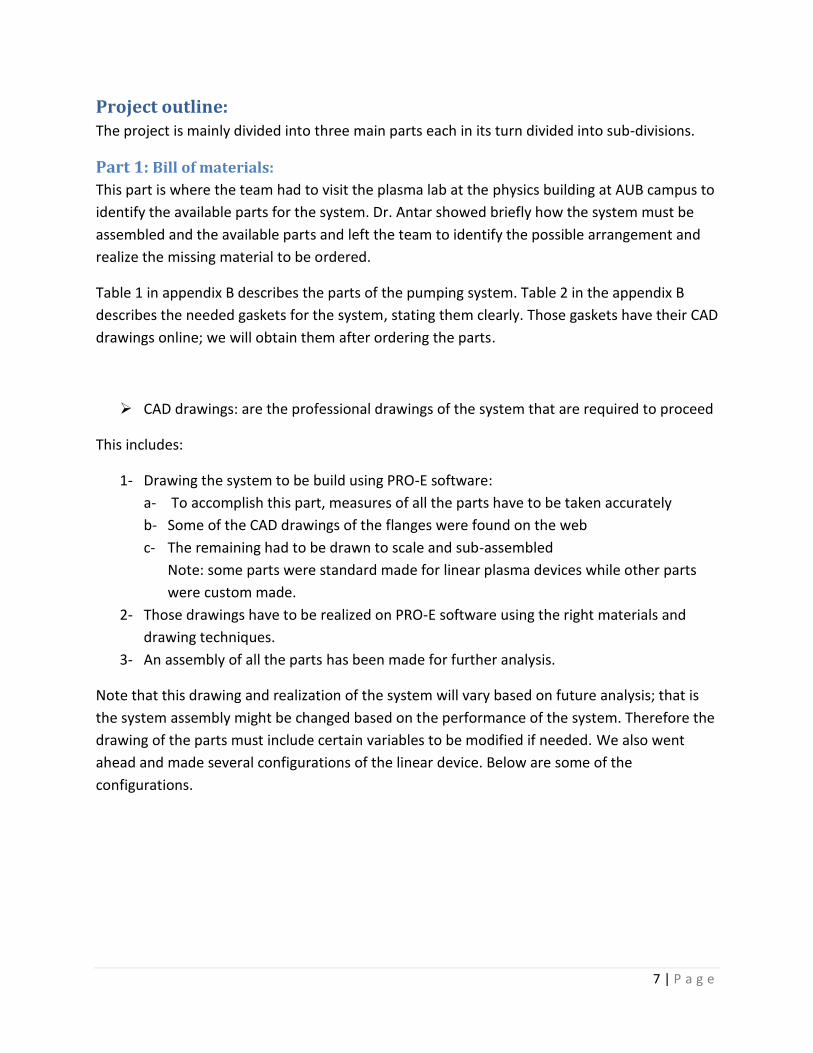
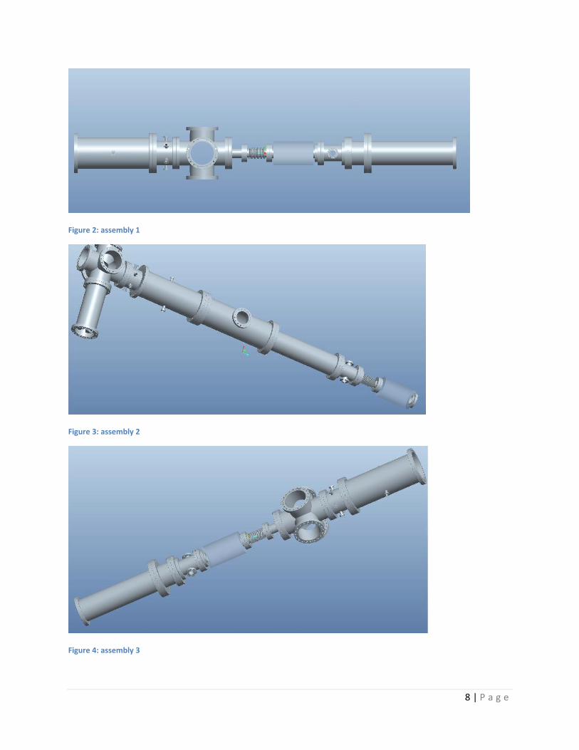
Note that this drawing and realization of the system will vary based on future analysis; that is
the system assembly might be changed based on the performance of the system. Therefore the
drawing of the parts must include certain variables to be modified if needed. We also went
ahead and made several configurations of the linear device. Below are some of the
configurations.
8 | P a g e
Figure 2: assembly 1
Figure 3: assembly 2
Figure 4: assembly 3
9 | P a g e
Part 2: Identification of the missing material:
To assemble the linear plasma device the system must include all the needed parts and their
complements; that is the flanges are to be assembled linearly separated by gaskets (O-rings) to
insure proper functioning of the system and foremost safety.
Research was made to ensure the missing parts are ordered properly. O-rings presentation
found in appendix B served as a good reference to choose the Gaskets. A table of required
gaskets is also found in appendix B.
Bolts: there are approximately 400 bolts used in the system. A table is included in appendix B to
elaborate on the specifications.
Part 3: Support structure
This structure is the base of our project. The linear plasma device will be held on a base support
structure that will be mobile for modifying the arrangement of the parts. Several support
structures were discussed in the meeting with the members as well as with the lab technicians
to check the availability of manufacturing them at the shops.
Step 1: weighing all the parts available at the lab to have an overall weigh that will help in
analyzing the support structure.
Step 2: force, shear, stress and bending diagrams analysis have to be made to ensure a safety
factor when working on the structure. This analysis is still being processed.
Step 3: a rough drawing has to be made for the structure. Basically two rails will lie on a
rectangular support. Mobile arms are clamped to the rails. Clamps are welded on the arms to
hold the flanges in place.
The support structure looks as follows
10 | P a g e
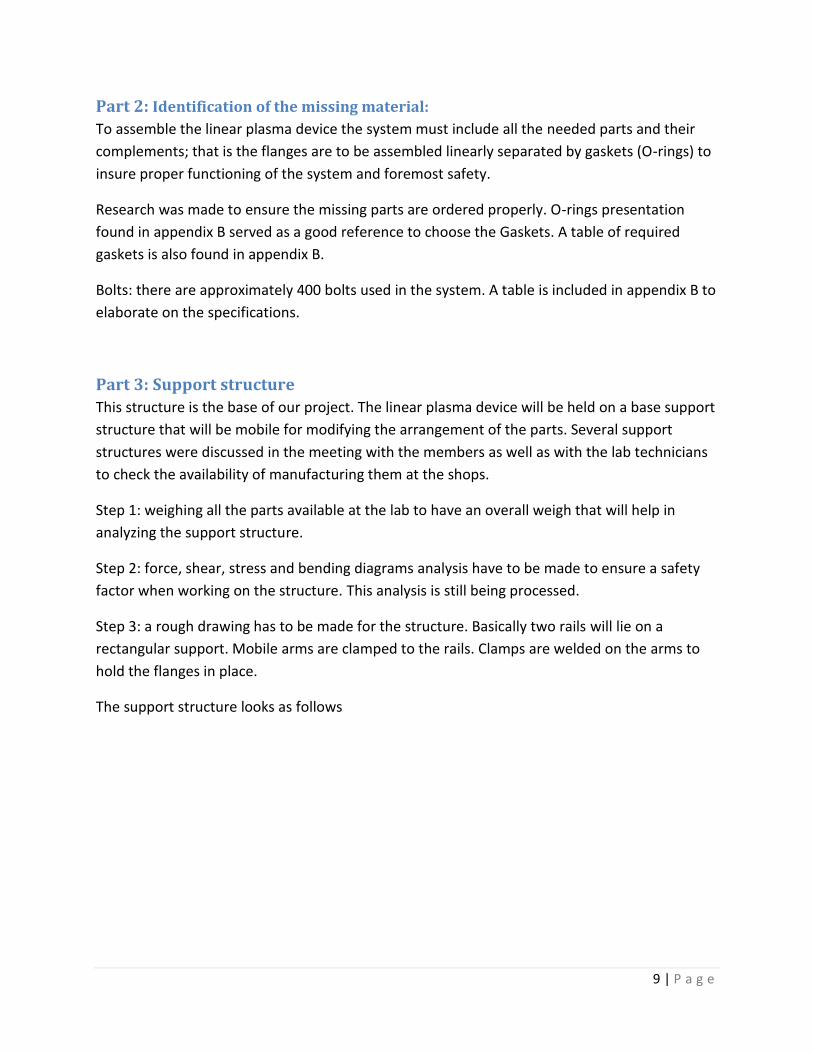
Figure 5: rendering of support structure
The blue part is the support structure that we intend to construct. This image is taken from the
internet and serves just as an example. As for the design of the real support structure and its
drawings they are still not ready.
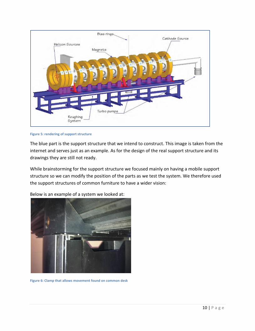
While brainstorming for the support structure we focused mainly on having a mobile support
structure so we can modify the position of the parts as we test the system. We therefore used
the support structures of common furniture to have a wider vision:
Below is an example of a system we looked at:
Figure 6: Clamp that allows movement found on common desk
11 | P a g e
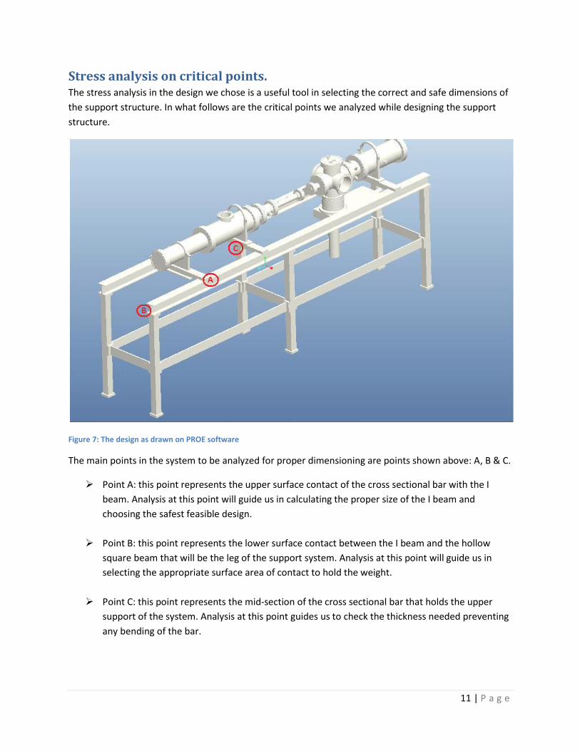
Stress analysis on critical points. The stress analysis in the design we chose is a useful tool in selecting the correct and safe dimensions of
the support structure. In what follows are the critical points we analyzed while designing the support
structure.
Figure 7: The design as drawn on PROE software
The main points in the system to be analyzed for proper dimensioning are points shown above: A, B & C.
Point A: this point represents the upper surface contact of the cross sectional bar with the I
beam. Analysis at this point will guide us in calculating the proper size of the I beam and
choosing the safest feasible design.
Point B: this point represents the lower surface contact between the I beam and the hollow
square beam that will be the leg of the support system. Analysis at this point will guide us in
selecting the appropriate surface area of contact to hold the weight.
Point C: this point represents the mid-section of the cross sectional bar that holds the upper
support of the system. Analysis at this point guides us to check the thickness needed preventing
any bending of the bar.
12 | P a g e
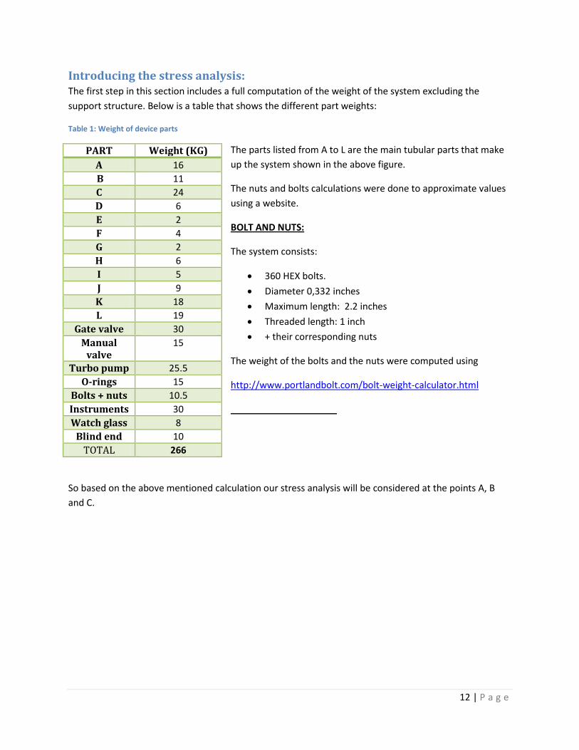
Introducing the stress analysis: The first step in this section includes a full computation of the weight of the system excluding the
support structure. Below is a table that shows the different part weights:
Table 1: Weight of device parts
The parts listed from A to L are the main tubular parts that make
up the system shown in the above figure.
The nuts and bolts calculations were done to approximate values
using a website.
BOLT AND NUTS:
The system consists:
360 HEX bolts.
Diameter 0,332 inches
Maximum length: 2.2 inches
Threaded length: 1 inch
+ their corresponding nuts
The weight of the bolts and the nuts were computed using
http://www.portlandbolt.com/bolt-weight-calculator.html
So based on the above mentioned calculation our stress analysis will be considered at the points A, B
and C.
PART Weight (KG)
A 16
B 11
C 24
D 6
E 2
F 4
G 2
H 6
I 5
J 9
K 18
L 19
Gate valve 30
Manual valve
15
Turbo pump 25.5
O-rings 15
Bolts + nuts 10.5
Instruments 30
Watch glass 8
Blind end 10
TOTAL 266
13 | P a g e
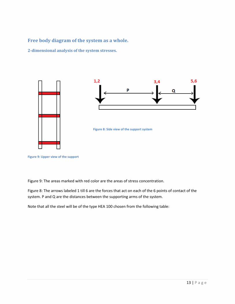
Free body diagram of the system as a whole.
2-dimensional analysis of the system stresses.
Figure 9: Upper view of the support
Figure 9: The areas marked with red color are the areas of stress concentration.
Figure 8: The arrows labeled 1 till 6 are the forces that act on each of the 6 points of contact of the
system. P and Q are the distances between the supporting arms of the system.
Note that all the steel will be of the type HEA 100 chosen from the following table:
Figure 8: Side view of the support system
14 | P a g e
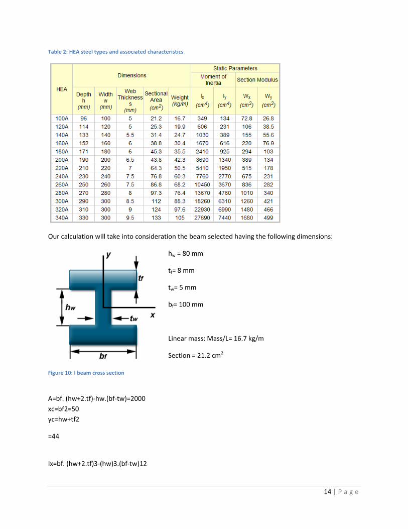
Table 2: HEA steel types and associated characteristics
Our calculation will take into consideration the beam selected having the following dimensions:
hw = 80 mm
tf= 8 mm
tw= 5 mm
bf= 100 mm
Linear mass: Mass/L= 16.7 kg/m
Section = 21.2 cm2
A=bf. (hw+2.tf)-hw.(bf-tw)=2000
xc=bf2=50
yc=hw+tf2
=44
Ix=bf. (hw+2.tf)3-(hw)3.(bf-tw)12
Figure 10: I beam cross section
15 | P a g e
=3,319,466 mm4
Iy=2.tf.(bf)3+hw.(tw)312
=1,334,166 mm4
Ixy=0
=0
Ip=bf.(hw+2.tf)3-(hw)3.(bf-tw)12+2.tf.(bf)3+hw.(tw)312
=4,653,633 mm4
We will take a modulus of elasticity E= 200 GPA.
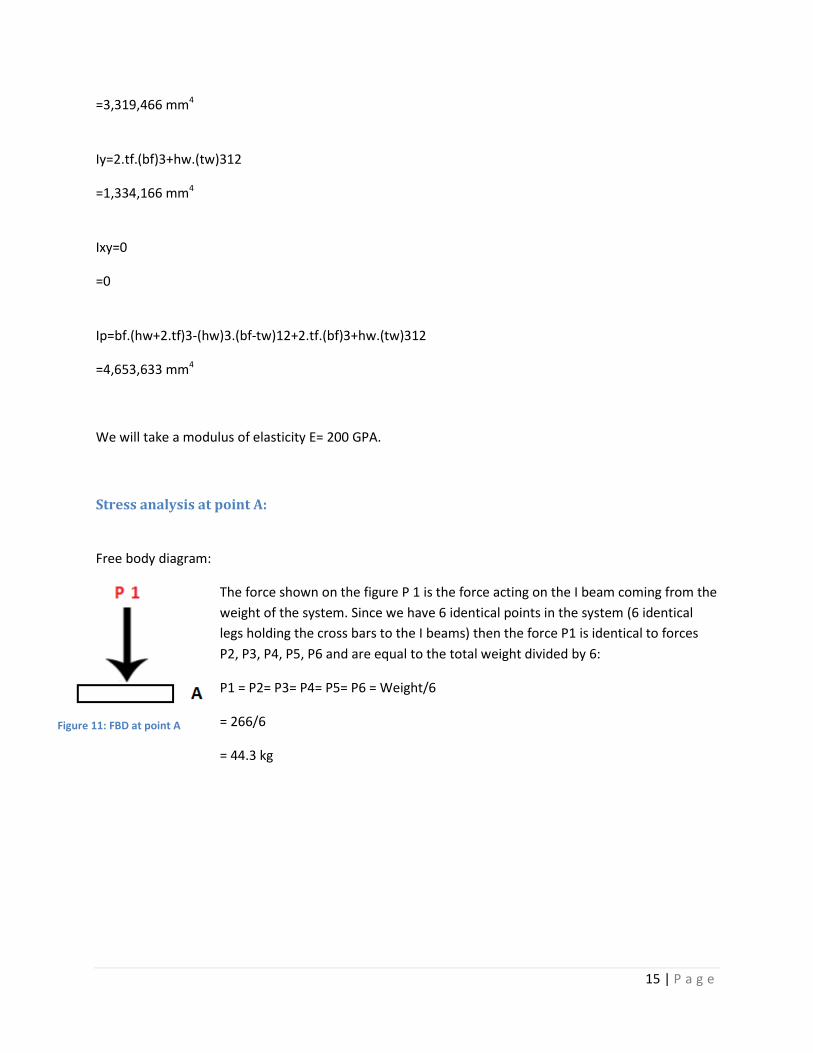
Stress analysis at point A:
Free body diagram:
The force shown on the figure P 1 is the force acting on the I beam coming from the
weight of the system. Since we have 6 identical points in the system (6 identical
legs holding the cross bars to the I beams) then the force P1 is identical to forces
P2, P3, P4, P5, P6 and are equal to the total weight divided by 6:
P1 = P2= P3= P4= P5= P6 = Weight/6
= 266/6
= 44.3 kg
Figure 11: FBD at point A
16 | P a g e
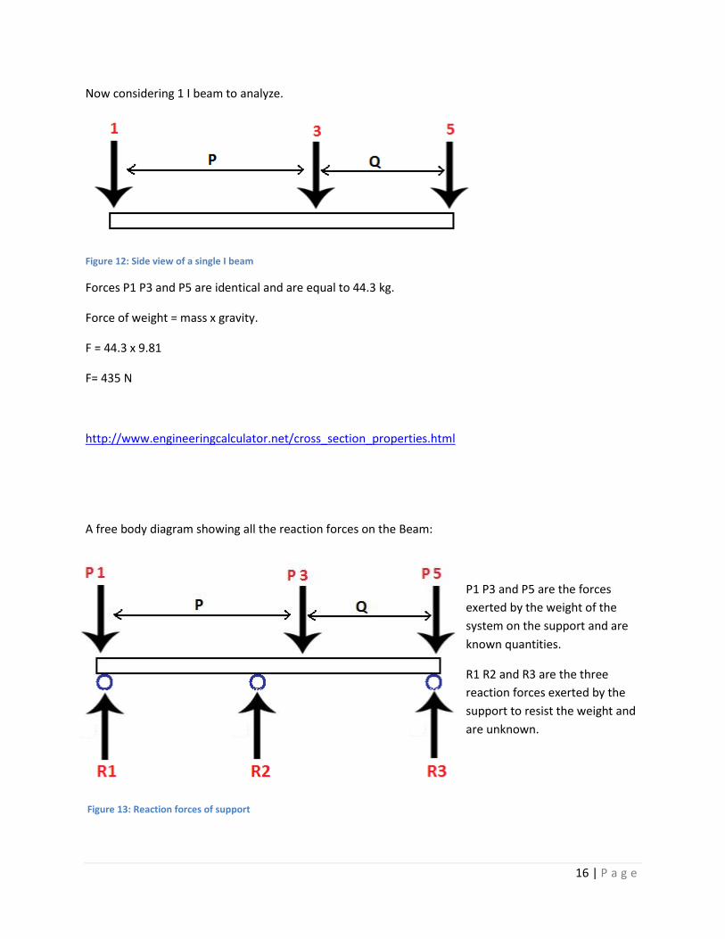
Now considering 1 I beam to analyze.
Figure 12: Side view of a single I beam
Forces P1 P3 and P5 are identical and are equal to 44.3 kg.
Force of weight = mass x gravity.
F = 44.3 x 9.81
F= 435 N
http://www.engineeringcalculator.net/cross_section_properties.html
A free body diagram showing all the reaction forces on the Beam:
P1 P3 and P5 are the forces
exerted by the weight of the
system on the support and are
known quantities.
R1 R2 and R3 are the three
reaction forces exerted by the
support to resist the weight and
are unknown.
Figure 13: Reaction forces of support
17 | P a g e
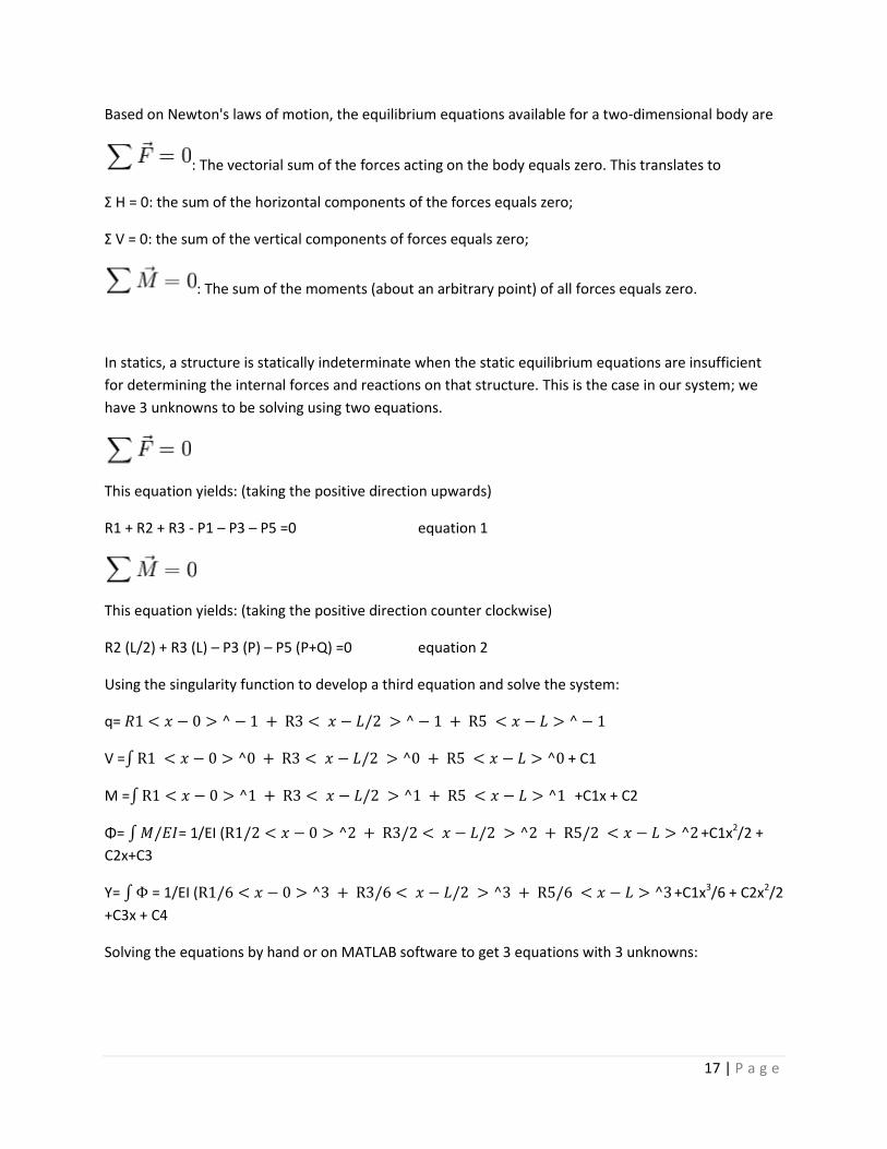
Based on Newton's laws of motion, the equilibrium equations available for a two-dimensional body are
: The vectorial sum of the forces acting on the body equals zero. This translates to
Σ H = 0: the sum of the horizontal components of the forces equals zero;
Σ V = 0: the sum of the vertical components of forces equals zero;
: The sum of the moments (about an arbitrary point) of all forces equals zero.
In statics, a structure is statically indeterminate when the static equilibrium equations are insufficient
for determining the internal forces and reactions on that structure. This is the case in our system; we
have 3 unknowns to be solving using two equations.
This equation yields: (taking the positive direction upwards)
R1 + R2 + R3 - P1 – P3 – P5 =0 equation 1
This equation yields: (taking the positive direction counter clockwise)
R2 (L/2) + R3 (L) – P3 (P) – P5 (P+Q) =0 equation 2
Using the singularity function to develop a third equation and solve the system:
q=
V = + C1
M = +C1x + C2
Φ= = 1/EI ( +C1x2/2 +
C2x+C3
Y= = 1/EI ( +C1x3/6 + C2x2/2
+C3x + C4
Solving the equations by hand or on MATLAB software to get 3 equations with 3 unknowns:
18 | P a g e
The next step after finding the reaction forces is to draw the shear and bending moment diagram of the
system
Next is to find the point of maximum moment
Compute at that point the yield stress
Find the safety factor
Check if the safety factor is suitable
If it is keep the 10cm wide I beam; if not recalculate using a wider beam.
In the following calculations R2 is eliminated to make the problem a 2 unknowns and 2 equations.
∑F along y=0
-P1-P3-P5+R1+R3= 0
R1+R3 = 435x3
R1+R3= 1305N
∑M on R1 =0 (taking clockwise as the positive direction)
P3(p)+P5(p) +P5 (L) –R3(L) =0
R3(L)= P3(p)+P5(L)
R3= {P3(p)+p5(L)}/L
R3= 435x4 + 435x2.8 / 4
R3= 740N
R1=565N
2) Shear and moment diagram:
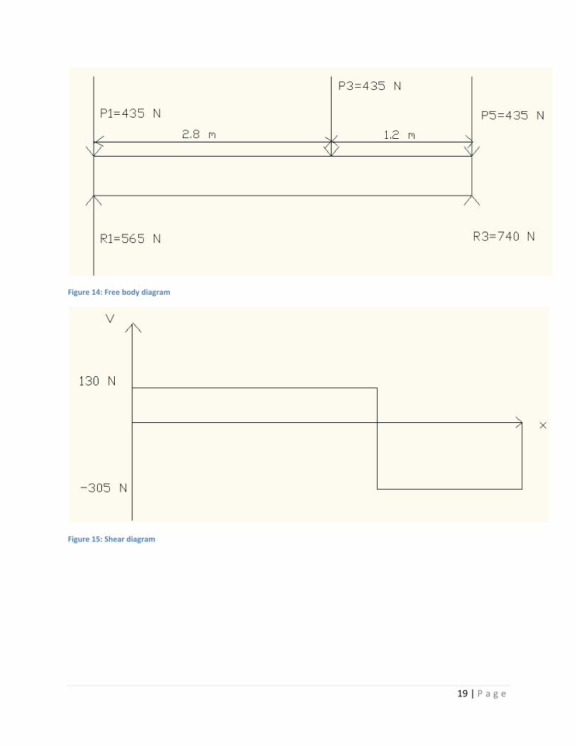
19 | P a g e
Figure 14: Free body diagram
Figure 15: Shear diagram
20 | P a g e
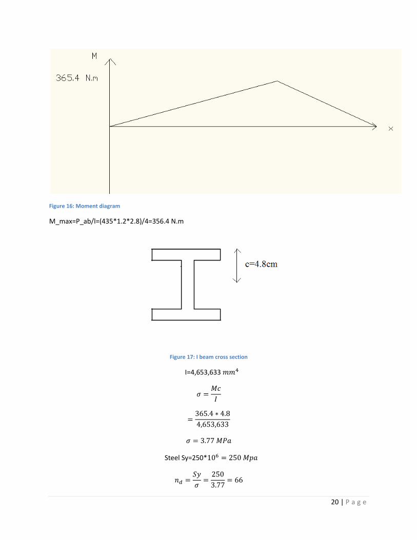
Figure 16: Moment diagram
M_max=P_ab/l=(435*1.2*2.8)/4=356.4 N.m
Figure 17: I beam cross section
I=4,653,633
Steel Sy=250*
21 | P a g e
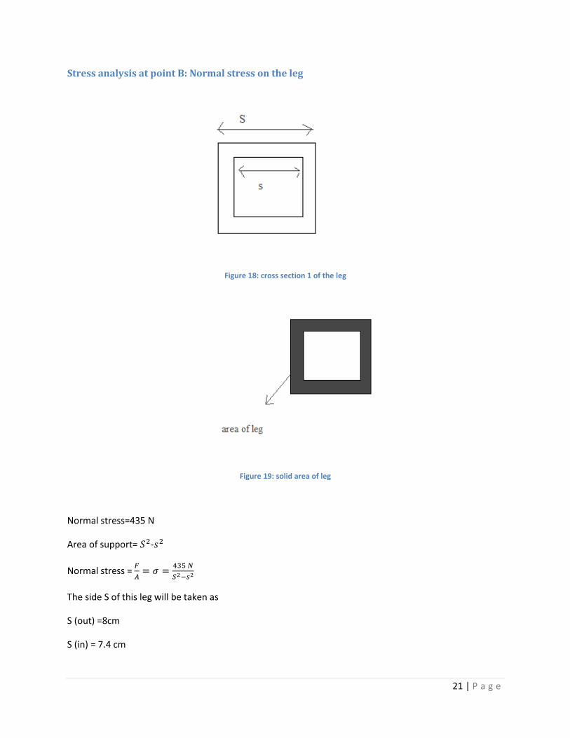
Stress analysis at point B: Normal stress on the leg
Figure 18: cross section 1 of the leg
Figure 19: solid area of leg
Normal stress=435 N
Area of support= -
Normal stress =
The side S of this leg will be taken as
S (out) =8cm
S (in) = 7.4 cm
22 | P a g e
Thus a thickness of 3 mm per side
Based on the calculation:
Normal stress
Steel Sy=250*
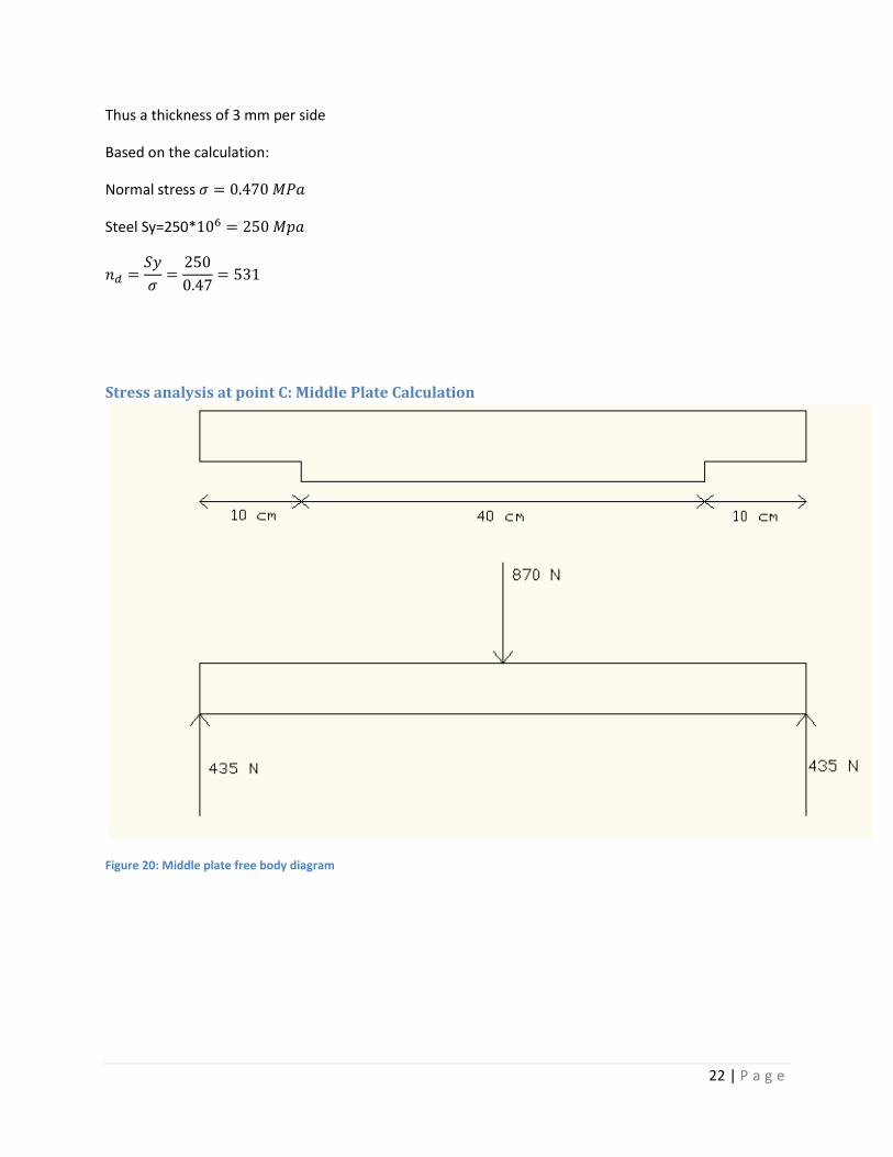
Stress analysis at point C: Middle Plate Calculation
Figure 20: Middle plate free body diagram
23 | P a g e
Figure 21: Middle plate sheer diagram
Figure 22: Middle plate moment diagram
Mmax=Pl/4
Mmax =(435*0.5)/4
Mmax =54.375 N.m
Figure 23: middle plate geometry
24 | P a g e
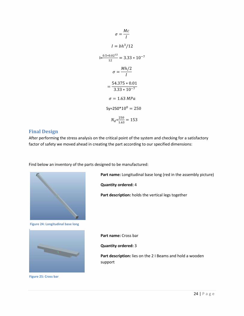
I=
Sy=250*
=
Final Design After performing the stress analysis on the critical point of the system and checking for a satisfactory
factor of safety we moved ahead in creating the part according to our specified dimensions:
Find below an inventory of the parts designed to be manufactured:
Part name: Longitudinal base long (red in the assembly picture)
Quantity ordered: 4
Part description: holds the vertical legs together
Part name: Cross bar
Quantity ordered: 3
Part description: lies on the 2 I Beams and hold a wooden
support
Figure 24: Longitudinal base long
Figure 25: Cross bar
25 | P a g e
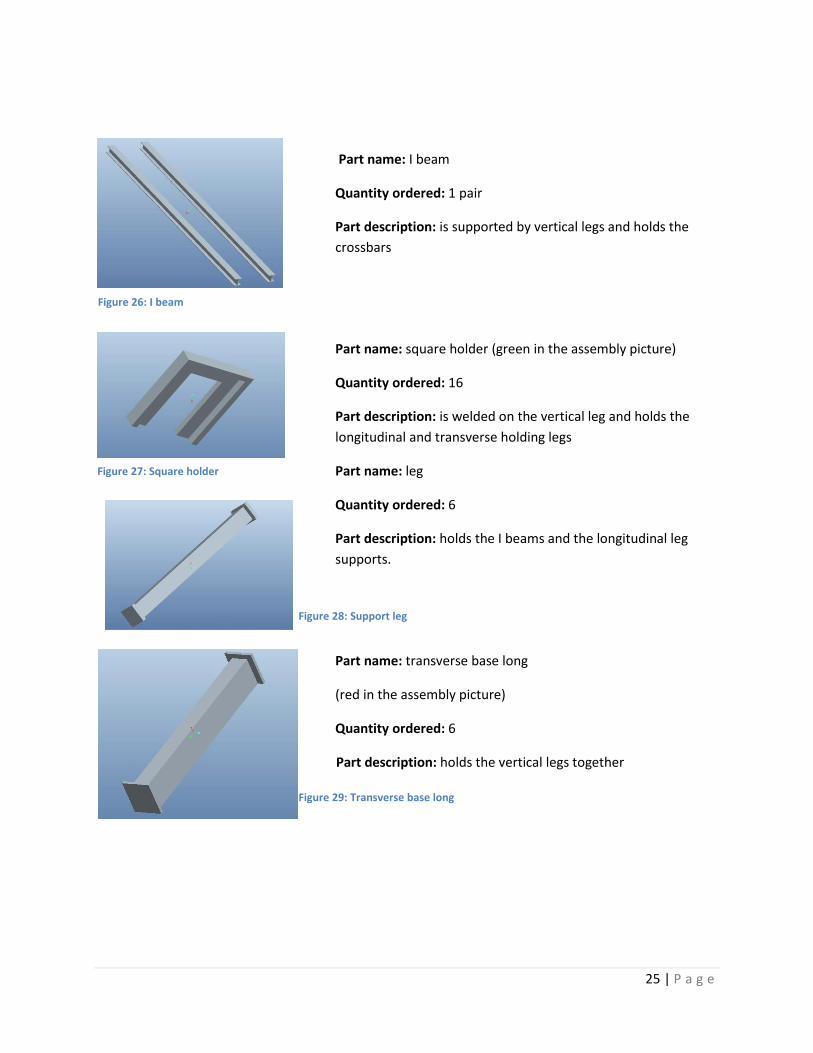
Part name: I beam
Quantity ordered: 1 pair
Part description: is supported by vertical legs and holds the
crossbars
Part name: square holder (green in the assembly picture)
Quantity ordered: 16
Part description: is welded on the vertical leg and holds the
longitudinal and transverse holding legs
Part name: leg
Quantity ordered: 6
Part description: holds the I beams and the longitudinal leg
supports.
Part name: transverse base long
(red in the assembly picture)
Quantity ordered: 6
Part description: holds the vertical legs together
Figure 26: I beam
Figure 28: Support leg
Figure 29: Transverse base long
Figure 27: Square holder
26 | P a g e
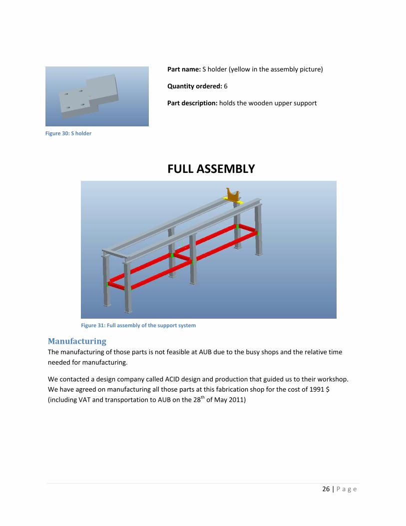
Part name: S holder (yellow in the assembly picture)
Quantity ordered: 6
Part description: holds the wooden upper support
FULL ASSEMBLY
Manufacturing The manufacturing of those parts is not feasible at AUB due to the busy shops and the relative time
needed for manufacturing.
We contacted a design company called ACID design and production that guided us to their workshop.
We have agreed on manufacturing all those parts at this fabrication shop for the cost of 1991 $
(including VAT and transportation to AUB on the 28th of May 2011)
Figure 30: S holder
Figure 31: Full assembly of the support system
27 | P a g e
Pumping system
The pumping system: The pumping system is needed to accomplish two goals:
1. Create a near perfect vacuum (high vacuum) with a pressure of 10-9 Torr.
2. Inject hydrogen gas at a steady flow rate into the vacuum chamber to be ionized and turned
into plasma.
The vacuum process:
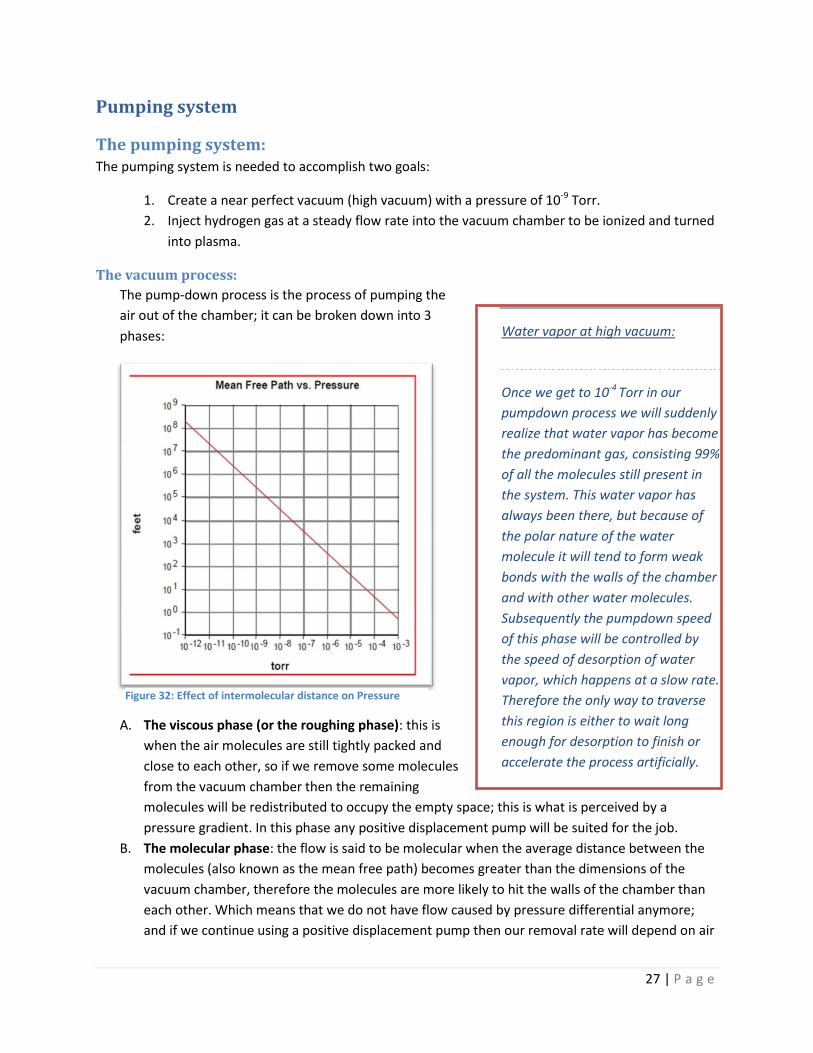
The pump-down process is the process of pumping the
air out of the chamber; it can be broken down into 3
phases:
A. The viscous phase (or the roughing phase): this is
when the air molecules are still tightly packed and
close to each other, so if we remove some molecules
from the vacuum chamber then the remaining
molecules will be redistributed to occupy the empty space; this is what is perceived by a
pressure gradient. In this phase any positive displacement pump will be suited for the job.
B. The molecular phase: the flow is said to be molecular when the average distance between the
molecules (also known as the mean free path) becomes greater than the dimensions of the
vacuum chamber, therefore the molecules are more likely to hit the walls of the chamber than
each other. Which means that we do not have flow caused by pressure differential anymore;
and if we continue using a positive displacement pump then our removal rate will depend on air
Water vapor at high vacuum:
Once we get to 10-4 Torr in our
pumpdown process we will suddenly
realize that water vapor has become
the predominant gas, consisting 99%
of all the molecules still present in
the system. This water vapor has
always been there, but because of
the polar nature of the water
molecule it will tend to form weak
bonds with the walls of the chamber
and with other water molecules.
Subsequently the pumpdown speed
of this phase will be controlled by
the speed of desorption of water
vapor, which happens at a slow rate.
Therefore the only way to traverse
this region is either to wait long
enough for desorption to finish or
accelerate the process artificially.
Figure 32: Effect of intermolecular distance on Pressure
28 | P a g e
molecules wandering by chance into the pump and out of the system. This is why we need a
new type of pumps, high vacuum pumps which we will address later in more detail.
C. The transition phase: in this phase the flow can neither be characterized as viscous nor
molecular, it is a very complex phase that normally requires special consideration, but by the
way our system is designed we managed avoid the complexities of this phase by using both the
molecular pump and the roughing pump at the same time thus avoiding the need for complex
piping.
Choice of Pumps:
The hardest choice is choosing the right molecular pump for the process, once this is done then
we choose a suitable roughing pump that can support the molecular pump.
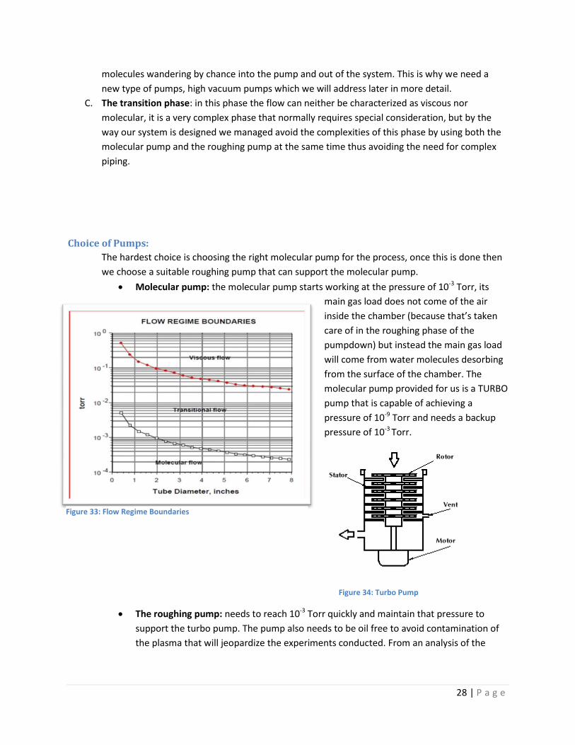
Molecular pump: the molecular pump starts working at the pressure of 10-3 Torr, its
main gas load does not come of the air
inside the chamber (because that’s taken
care of in the roughing phase of the
pumpdown) but instead the main gas load
will come from water molecules desorbing
from the surface of the chamber. The
molecular pump provided for us is a TURBO
pump that is capable of achieving a
pressure of 10-9 Torr and needs a backup
pressure of 10-3 Torr.
Figure 34: Turbo Pump
The roughing pump: needs to reach 10-3 Torr quickly and maintain that pressure to
support the turbo pump. The pump also needs to be oil free to avoid contamination of
the plasma that will jeopardize the experiments conducted. From an analysis of the
Figure 33: Flow Regime Boundaries
29 | P a g e
available pumps we concluded that a screw rotor oil free pump is our best choice. A
summary of the available widely used pumps is presented below:
Complete pumping System Design:
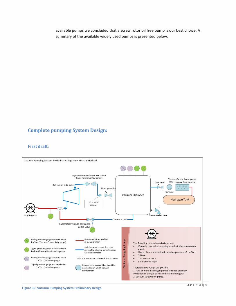
First draft:
Figure 35: Vacuum Pumping System Preliminary Design
30 | P a g e
Good points to be kept:
The pump down will be happening through 2 paths simultaneously, through the turbo pump and
through a separate pipe. This has several benefits, it allows maximum conductance and allows
the turbo pump to smoothly take over the molecular pump-down region, while avoiding
complex piping. At the transition pressure of 1 mTorr, the roughing line will automatically stop
the flow by using an automatic pressure control switch valve.
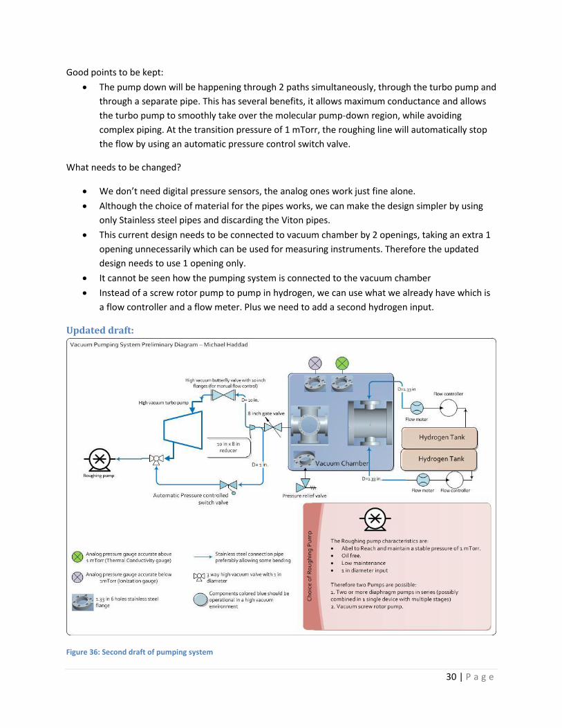
What needs to be changed?
We don’t need digital pressure sensors, the analog ones work just fine alone.
Although the choice of material for the pipes works, we can make the design simpler by using
only Stainless steel pipes and discarding the Viton pipes.
This current design needs to be connected to vacuum chamber by 2 openings, taking an extra 1
opening unnecessarily which can be used for measuring instruments. Therefore the updated
design needs to use 1 opening only.
It cannot be seen how the pumping system is connected to the vacuum chamber
Instead of a screw rotor pump to pump in hydrogen, we can use what we already have which is
a flow controller and a flow meter. Plus we need to add a second hydrogen input.
Updated draft:
Figure 36: Second draft of pumping system
31 | P a g e
Choice of pump: We previously establish that we needed an oil free roughing pump capable of
reaching and maintaining 10-3. After carefully reviewing the options available at the market we
concluded that the oil free pumps can either be diaphragm pumps or a rotor pump.
But the problem with diaphragm pumps is that they don’t reliably reach the target pressure.
And the rotor pump is too expensive.
Therefore we will opt for a vane pump, but it should be coupled with an oil trap to prevent oil
from leaking into the system that could be disruptive to the plasma creation process.
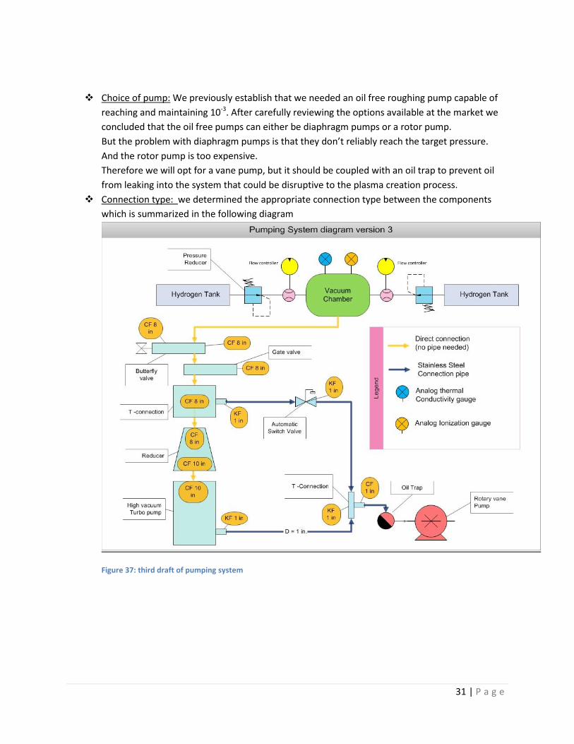
Connection type: we determined the appropriate connection type between the components
which is summarized in the following diagram
Figure 37: third draft of pumping system
32 | P a g e
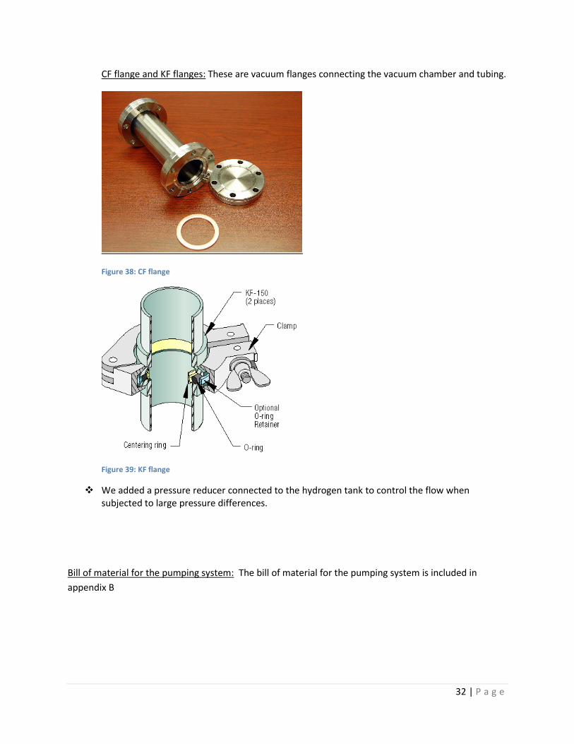
CF flange and KF flanges: These are vacuum flanges connecting the vacuum chamber and tubing.
Figure 38: CF flange
Figure 39: KF flange
We added a pressure reducer connected to the hydrogen tank to control the flow when subjected to large pressure differences.
Bill of material for the pumping system: The bill of material for the pumping system is included in
appendix B
33 | P a g e
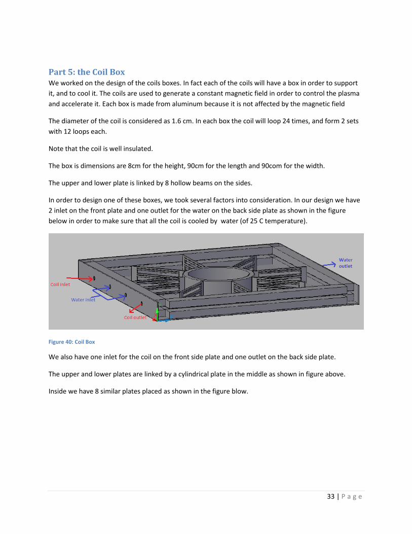
Part 5: the Coil Box We worked on the design of the coils boxes. In fact each of the coils will have a box in order to support
it, and to cool it. The coils are used to generate a constant magnetic field in order to control the plasma
and accelerate it. Each box is made from aluminum because it is not affected by the magnetic field
The diameter of the coil is considered as 1.6 cm. In each box the coil will loop 24 times, and form 2 sets
with 12 loops each.
Note that the coil is well insulated.
The box is dimensions are 8cm for the height, 90cm for the length and 90com for the width.
The upper and lower plate is linked by 8 hollow beams on the sides.
In order to design one of these boxes, we took several factors into consideration. In our design we have
2 inlet on the front plate and one outlet for the water on the back side plate as shown in the figure
below in order to make sure that all the coil is cooled by water (of 25 C temperature).
Figure 40: Coil Box
We also have one inlet for the coil on the front side plate and one outlet on the back side plate.
The upper and lower plates are linked by a cylindrical plate in the middle as shown in figure above.
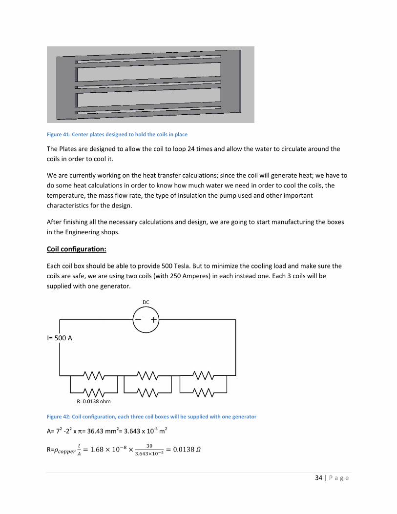
Inside we have 8 similar plates placed as shown in the figure blow.
34 | P a g e
Figure 41: Center plates designed to hold the coils in place
The Plates are designed to allow the coil to loop 24 times and allow the water to circulate around the
coils in order to cool it.
We are currently working on the heat transfer calculations; since the coil will generate heat; we have to
do some heat calculations in order to know how much water we need in order to cool the coils, the
temperature, the mass flow rate, the type of insulation the pump used and other important
characteristics for the design.
After finishing all the necessary calculations and design, we are going to start manufacturing the boxes
in the Engineering shops.
Coil configuration:
Each coil box should be able to provide 500 Tesla. But to minimize the cooling load and make sure the
coils are safe, we are using two coils (with 250 Amperes) in each instead one. Each 3 coils will be
supplied with one generator.
Figure 42: Coil configuration, each three coil boxes will be supplied with one generator
A= 72 -22 x π= 36.43 mm2= 3.643 x 10⁻⁵ m2
R=
35 | P a g e
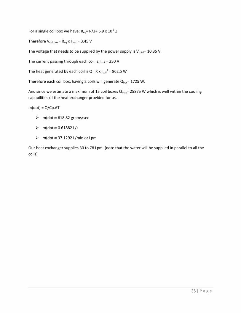
For a single coil box we have: Req= R/2= 6.9 x 10⁻³Ω
Therefore Vcoil box = Req x Imax = 3.45 V
The voltage that needs to be supplied by the power supply is Vtotal= 10.35 V.
The current passing through each coil is: Icoil = 250 A
The heat generated by each coil is Q= R x Icoil2 = 862.5 W
Therefore each coil box, having 2 coils will generate Qbox= 1725 W.
And since we estimate a maximum of 15 coil boxes Qmax= 25875 W which is well within the cooling
capabilities of the heat exchanger provided for us.
m(dot) = Q/Cp.ΔT
m(dot)= 618.82 grams/sec
m(dot)= 0.61882 L/s
m(dot)= 37.1292 L/min or Lpm
Our heat exchanger supplies 30 to 78 Lpm. (note that the water will be supplied in parallel to all the
coils)
36 | P a g e
Appendix A
Part 1) “Ethical and professional responsibilities”
This project, when it was first presented to our group, presented a lot of technical difficulties
and obstacles that we had to solve and get around. For emerging engineers such as ourselves,
it usually feels that the most important and vital objective of any project is to overcome the
technical needs and henceforth the project will be basically completed. However, and this may
sound a bit prescient, it never ends with just the physical and mathematic solutions. As with
everything else in life, there is no black and white, just shades of grey, and the field of
engineering is no different. We do not live in isolation from the rest of society, and issues that
might sound redundant when we’re going full throttle in our workplaces, such as philosophy,
religion, ethics, and law, are actually of grave importance to our success and failure. We are
constantly faced with decisions in the workplace (and life in general) that can define career and
life paths. Each decision we make, will produce ripples in the very fabric of society that can
have endless consequences. Therefore, we have established a set of general guidelines and
structures, rather using the “rules” or “law”, which sounds altogether more severe. These
guidelines include the “Order of Engineers Code of Ethic” and the ASME guidebook as well.
Now, as I have pointed out and from what we learned, no project can come close to being
considered completed if it doesn’t go through a rigorous ethical examination, not by anyone
other than its innovators. So going through the “Order of Engineers Code of Ethic”, we have
found that most guidelines were committed to not through conscious action, but rather
through our normal behaviorally patterns, since most of these ethical codes were gained in life,
and henceforth applied in engineering. A basic example of this perfunctory ethical behavior is
the following article: “Engineers shall perform services only in the areas of their competence.”
Obviously, it goes without saying that we are working in a field that is very much own. There is
also the example of not causing someone harm on purpose. The point we’re trying to make is
that some ethical constraints need not be even considered if the engineer is a sane and fully
functioning member of society. Any discrepancy in that and the problem extends beyond just
37 | P a g e
the realm of engineering and becomes a fully-fledged social problem. Now that we covered
slithers of examples that poses no challenge, lets us go into something much more
“challenging” shall we say. When, at the beginning, we were discussing the advantages reaped
by producing such a wonderful and exciting project, the professor told us that this could be
useful in our future careers. Now this might sound like an exciting prospect for us in the group,
but there is a catch, one that occurred to us simultaneously with the compliment: what if in the
foreseeable future, a company offered us well-paid, lofty positions, to work on a project highly
relevant to the one we are working on now. What then? What if the company told us they
wanted to see the documents we produced in the university, do we allow such a breach? Even
though it will probably help our careers, it will produce a massive ethical dilemma: the freedom
and right to thought. The following is the general article that deals with this train of ethical
thought: “Engineers shall not disclose, without con sent, confidential information concerning
the business affairs or technical processes of any present or former client or employer, or public
body on which they serve.” Therefore as you can see, the nature of this project, which very
different and in general much more advanced than our previous example, can cause some
gigantic ethical dilemmas. The larger the ambition of the project, the bigger the ripple it causes
in society.
Part 2) “Understanding in a social context”
This is a wonderful issue to discuss, and in my humble opinion, the whole purpose of this
project. To put it in an extremely simple, “non-technical” way: our project produces clean
renewable energy. Now you may have heard about our little issue with the depleting fossil fuel
reservoirs, and thus the huge energy crisis that awaits us in the not so distant future. At every
level, from high-school science fairs, to international crisis meetings, everyone is discussing the
energy topic, and of course the topics surrounding it as well, from pollution, to the advantages
and disadvantages of nuclear energy and who should have it in the first place, and several other
topics intertwined under the main heading of “energy”. It can truly be considered one of the
paramount issues facing the international society. Therefore the search for clean, renewable
energy is at its most fervent, and we are working on one of the scenarios that might eventually
38 | P a g e
be the solution to our problems. Our project, the “plasma vacuum chamber” can be described
quite simply as a machine that turns air into energy. Now, this is a very child-like and simple
description to our project that masks the intricate process that is undergoing, but in essence
this is its purpose, and this is of course how it will be presented to the masses. This project will
be able to produce and clean, renewable energy and if rough estimates are taken into
consideration, at prices and costs much, much lower than producing energy in say a fossil-fuel
based power plant. Therefore, we might say proudly, that we as engineers are working for the
greater good of all of humanity, and while our efforts might barely affect the society in greater
sense, the idea that we contributed to the improvement of the quality of man’s life is truly
satisfying.
Part 3) “Project as a Business Model”
As optimistic as we sound in the previous part about the applicability and practicality of the
“Plasma Vacuum chamber” we must also sound a note of caution. The designs and plans are far
from the finished article, and it will require further advancement in technology to be able to
fully perfect the machine. Especially considering that arguably the machine’s most vital
component, the electric field, is still rough and rarely produces the effect that engineers seek in
such machines. Therefore, with our efforts, instead of producing the finished article, we are
paving the way for future generations, who will have more advanced technologies at their
disposals, to perfect our work. In the engineering world, results cannot be attained just by one
trial, one experiment, or one attempt to innovate. It is a gradual process where various
engineers pool in their efforts and talents to slowly but surely attain the results that are
desired. Even then, the work of engineer is never over. We must always seek to improve,
modify and ultimately perfect our designs, for the greater good of humanity.
39 | P a g e
Appendix B
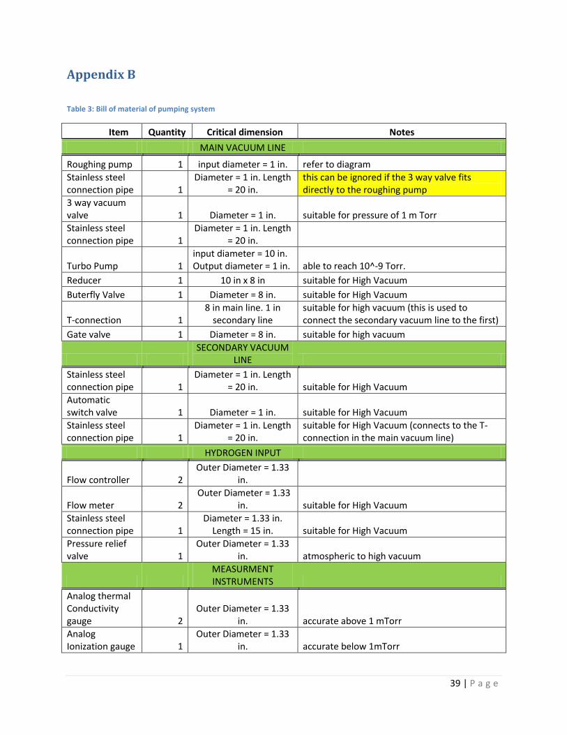
Table 3: Bill of material of pumping system
Item Quantity Critical dimension Notes
MAIN VACUUM LINE
Roughing pump 1 input diameter = 1 in. refer to diagram
Stainless steel connection pipe 1
Diameter = 1 in. Length = 20 in.
this can be ignored if the 3 way valve fits directly to the roughing pump
3 way vacuum valve 1 Diameter = 1 in. suitable for pressure of 1 m Torr
Stainless steel connection pipe 1
Diameter = 1 in. Length = 20 in.
Turbo Pump 1 input diameter = 10 in. Output diameter = 1 in. able to reach 10^-9 Torr.
Reducer 1 10 in x 8 in suitable for High Vacuum
Buterfly Valve 1 Diameter = 8 in. suitable for High Vacuum
T-connection 1 8 in main line. 1 in
secondary line suitable for high vacuum (this is used to connect the secondary vacuum line to the first)
Gate valve 1 Diameter = 8 in. suitable for high vacuum
SECONDARY VACUUM
LINE
Stainless steel connection pipe 1
Diameter = 1 in. Length = 20 in. suitable for High Vacuum
Automatic switch valve 1 Diameter = 1 in. suitable for High Vacuum
Stainless steel connection pipe 1
Diameter = 1 in. Length = 20 in.
suitable for High Vacuum (connects to the T-connection in the main vacuum line)
HYDROGEN INPUT
Flow controller 2 Outer Diameter = 1.33
in.
Flow meter 2 Outer Diameter = 1.33
in. suitable for High Vacuum
Stainless steel connection pipe 1
Diameter = 1.33 in. Length = 15 in. suitable for High Vacuum
Pressure relief valve 1
Outer Diameter = 1.33 in. atmospheric to high vacuum
MEASURMENT INSTRUMENTS
Analog thermal Conductivity gauge 2
Outer Diameter = 1.33 in. accurate above 1 mTorr
Analog Ionization gauge 1
Outer Diameter = 1.33 in. accurate below 1mTorr
40 | P a g e
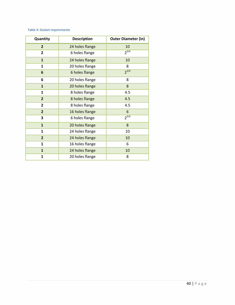
Table 4: Gasket requirements
Quantity Description Outer Diameter (in)
2 24 holes flange 10
2 6 holes flange 23/4
1 24 holes flange 10
1 20 holes flange 8
6 6 holes flange 23/4
6 20 holes flange 8
1 20 holes flange 8
1 8 holes flange 4.5
2 8 holes flange 4.5
2 8 holes flange 4.5
2 16 holes flange 6
3 6 holes flange 23/4
1 20 holes flange 8
1 24 holes flange 10
2 24 holes flange 10
1 16 holes flange 6
1 24 holes flange 10
1 20 holes flange 8


![Final year project-Mech 502 : The lebanese linear plasma ... final report.pdf · [FINAL YEAR PROJECT-MECH 502 : THE LEBANESE LINEAR PLASMA DEVICE] Ralph Ghazal 200800747 Nareg Oughourlian](https://img.pdfslide.us/doc/110x75/5f4410ef5861c505af2ad40c/final-year-project-mech-502-the-lebanese-linear-plasma-final-final-year.jpg)