Embed Size (px)
Citation preview
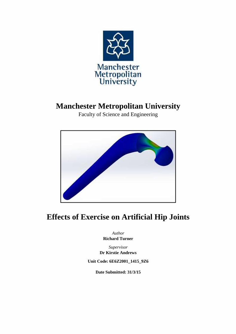
Manchester Metropolitan University Faculty of Science and Engineering
Effects of Exercise on Artificial Hip Joints
Author
Richard Turner
Supervisor
Dr Kirstie Andrews
Unit Code: 6E6Z2001_1415_9Z6
Date Submitted: 31/3/15
2
Acknowledgements
I would like to thank Dr Kirstie Andrews for her help and guidance throughout this project and Dave
Ingham of Zimmer Orthopaedics for providing information on prosthesis components.
3
Summary
This report provides an investigation into the effects of exercise on artificial hip joint prosthesis
components. Using finite element analysis, a Charnley-style femoral stem and acetabular cup were
simulated using peak loads and angles of flexion when the body is in walking, jogging, and cycling
motion. The components were modelled using a range of materials to determine the optimum
combination of material choice for the femoral head and acetabular cup.
Results from the simulations showed that for high impact exercises with low repetition of movement, a
stainless steel femoral stem and cobalt chromium acetabular cup was the optimum combination to
prevent failure from excessive displacement and cracking in the components. For low impact exercises
with highly repetitive movement, a titanium alloy (Ti-6Al-4V) femoral stem and ceramic acetabular
cup was the optimum combination to prevent failure from excessive wear-rate of the prosthesis.
4
PROJECT MANAGEMENT REPORT 2015
CONSULTATION WITH YOUR PROJECT SUPERVISOR
September: 29 October: 6, 13, 20, 27 November: 3, 10, 17, 24
December: 1, 8, 19 January 12, 19, 26 February 2, 9, 16, 25
March: 2, 9, 16, 23
INITIATIVE
Made contact with employee of Zimmer orthopaedics to discuss prosthesis models and
materials.
Modelled hip prosthesis in two components as opposed to a complete assembly to overcome
simulation limitations.
Converged the model to find the optimum mesh size to produce the most accurate results.
NEW TECHNIQUES
Improved CAD skills and learnt how to conduct FEA on a range of components.
Used free body diagram to analyse forces present on the hip to use as values for simulation.
Using two result plots of convergence graph to identify anomalies.
CREATIVITY & INNOVATION
Used CAD to produce a scale model of an acetabular cup component to be used in
conjunction with femoral stem for simulation.
Determined angle at which resultant force at hip will act relative to the ground and
calculated the magnitude of resultant force in terms of bodyweight.
Designed method of calibrating CAD model for any exercise providing the angle of flexion
and peak load is known.
5
Contents
Nomenclature 9
Table of Figures 8
Table of Tables 10
Introduction 11
Aim 12
Objectives 12
Background
The Hip Joint 13
History of Hip Arthroplasty 16
Modern Day Hip Arthroplasty 18
Variations of Prostheses 20
Materials of Components 21
Life After Surgery 26
Method 27
Methodology
Forces Acting on Hip Joint 28
Effects of Exercise on Natural Hip 32
CAD Model
Stem Dimensions 35
Cup Dimensions 36
Finite Element Analysis
Assembled Model 37
Set-Up 38
Convergence 40
Configuration of Components for Exercise 42
Simulation Plots 44
Results 47
6
Interpretation of Results 48
Errors 51
Discussion 52
Conclusion 53
Future Work 54
References 56
Appendices 59
Preliminary Report 60
Weekly Record Sheet 69
Ethics Form 71
Risk Assessment Form 74
7
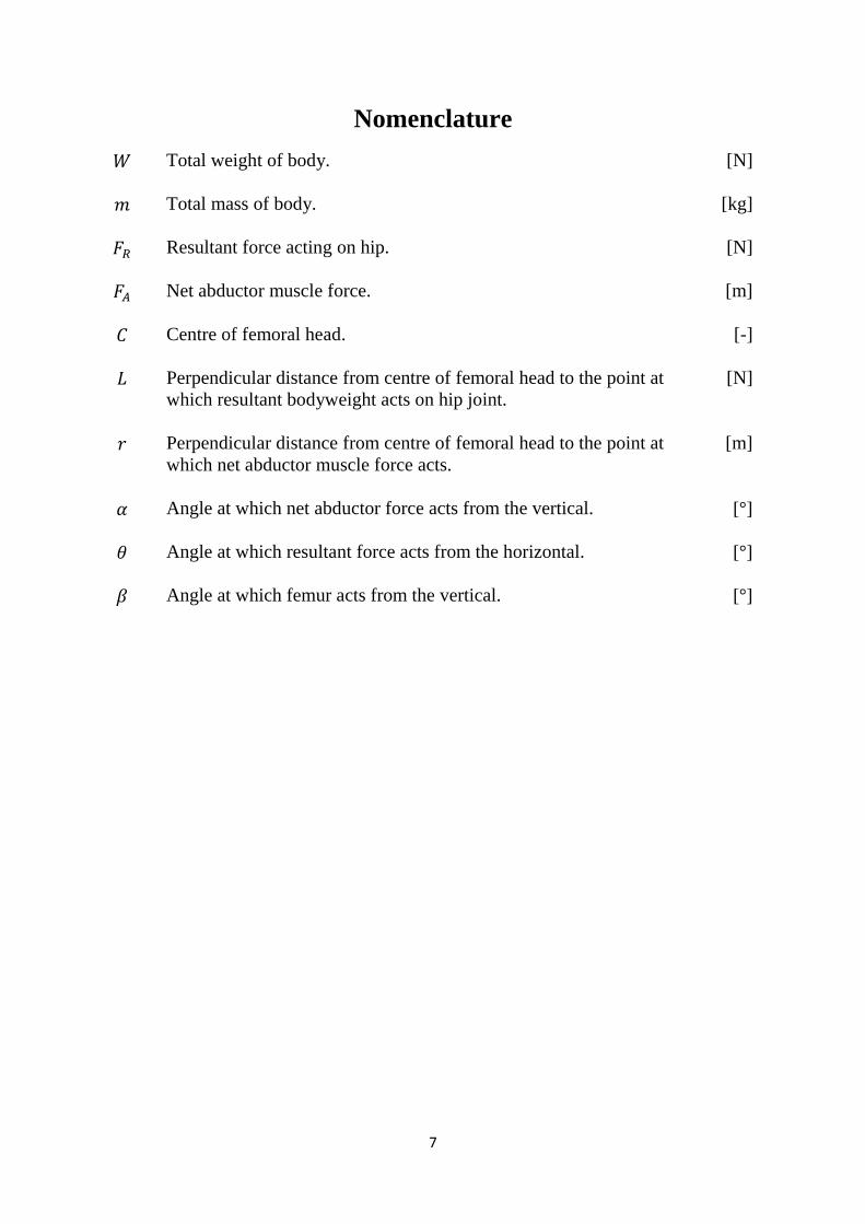
Nomenclature
𝑊 Total weight of body.
[N]
𝑚 Total mass of body.
[kg]
𝐹𝑅 Resultant force acting on hip.
[N]
𝐹𝐴 Net abductor muscle force.
[m]
𝐶 Centre of femoral head.
[-]
𝐿 Perpendicular distance from centre of femoral head to the point at
which resultant bodyweight acts on hip joint.
[N]
𝑟 Perpendicular distance from centre of femoral head to the point at
which net abductor muscle force acts.
[m]
𝛼 Angle at which net abductor force acts from the vertical.
[°]
𝜃 Angle at which resultant force acts from the horizontal.
[°]
𝛽 Angle at which femur acts from the vertical.
[°]
8
Table of Figures
Figure 1 The hip joint. [6] ..................................................................................................................... 13
Figure 3 Posterior view of hip joint. [6] ................................................................................................ 14
Figure 2 Anterior view of hip joint. [6] ................................................................................................ 14
Figure 6 Mckee-Farrar prostheses. [14] ................................................................................................ 16
Figure 7 Original Charnley prosthesis. [17] .......................................................................................... 17
Figure 8 Cross section of cemented stem in femur. [18] ...................................................................... 18
Figure 10 Substantial bone still attached to the acetabular component after revision surgery. [22] ..... 19
Figure 9 Osseointegration of bone. [21] ............................................................................................... 19
Figure 11 Comparison of cemented and uncemented methods of fixation. [25] .................................. 19
Figure 13 Prosthesis in position. [27] ................................................................................................... 20
Figure 12 McKee-Farrar prosthesis components. [27] ......................................................................... 20
Figure 14 Charnley prosthesis used to replace damaged hip joint. [29] ............................................... 20
Figure 15 Stress distribution of natural femur. [30] .............................................................................. 21
Figure 16 Stress distribution of hip prosthesis. [30] ............................................................................. 21
Figure 18 Ti-6Al-4V 40% porosity. [33] .............................................................................................. 22
Figure 17 Cancellous bone. [32] ........................................................................................................... 22
Figure 23 Ceramic on ceramic bearing. [41] ........................................................................................ 24
Figure 25 Comparison of wear rates for bearing materials. [36] .......................................................... 25
Figure 26 Free body diagram of hip joint in one-legged position. [51] ................................................ 29
Figure 27 Visualisation of forces acting on body when walking.[52] .................................................. 31
Figure 28 Planes of body. [54] .............................................................................................................. 33
Figure 29 Angle of flexion of hip. [55] ................................................................................................... 33
Figure 30 Average hip angle during gait analysis using a three dimensional musculoskeletal model
(Effect of hip angle on anterior hip joint force during gait, Lewis CL, Sahrmann SA, Moran DW,
2010.) .................................................................................................................................................... 33
Figure 31 Hip flexion-extension angle during gait cycle of human running. (Biomechanical Basis of
Human Movement, Hamill J, Knutzen KA, 2008, p. 365) ................................................................... 34
Figure 32 Hip flexion-extension angle range for cycling and other methods of activity. (Comparison
of elliptical training, stationary cycling, treadmill walking and overground walking, Damiano DL,
Norman T, Stanley CJ, Park HS, 2011 ................................................................................................. 34
Figure 33 Side view of assembled prosthesis showing angle of flexion. .............................................. 37
Figure 37 Fixed geometry on shaft and underside of flange of femoral stem. ..................................... 38
Figure 36 Fixed geometry on outer surface and ridges of acetabulum cup. ......................................... 38
Figure 43 Stem with 1.5mm mesh. ....................................................................................................... 40
Figure 42 Stem with 5mm mesh. .......................................................................................................... 40
Figure 44 Probing neck of femoral stem at split-line intersections....................................................... 40
Figure 45 Graph of convergence plot. .................................................................................................. 41
Figure 47 Resultant force position on femoral head. ............................................................................ 42
Figure 48 Resultant force position on acetabular cup. ......................................................................... 42
Figure 46 Visual configuration of components. .................................................................................... 42
Figure 51 Resultant force position on acetabular cup. .......................................................................... 42
Figure 53 Resultant force position on femoral head. ............................................................................ 43
Figure 54 Resultant force position on acetabular cup. .......................................................................... 43
Figure 55 Bar chart comparing max von Mises stress in femoral stem materials when under loading
from exercise. ........................................................................................................................................ 48
9
Figure 56 Bar chart comparing max von Mises stress in acetabulum cup materials when under loading
from exercise. ........................................................................................................................................ 48
Figure 57 Bar chart comparing max displacement in femoral stem materials when under loading from
exercise. ................................................................................................................................................ 49
Figure 58 Split bar chart comparing max displacement in acetabular cup materials when under loading
from exercise. ........................................................................................................................................ 49
Figure 59 Bar chart comparing max strain in femoral stem materials when under loading from
exercise. ................................................................................................................................................ 50
Figure 60 Split bar chart comparing max strain in acetabular cup materials when under loading from
exercise ................................................................................................................................................. 50
10
Table of Tables
Table 1 Summary of bearing materials. ................................................................................................ 25
Table 2 Properties of most common prosthesis materials. .................................................................... 25
Table 3 Comparison for activities with their corresponding peak loads. [51] ...................................... 32
Table 4 Resultant force for physical activity. ....................................................................................... 32
Table 5 Angle of flexion for physical activity. ..................................................................................... 34
Table 6 Convergence results. ................................................................................................................ 41
Table 7 Stress distribution values of femoral stem. .............................................................................. 44
Table 8 Stress distribution values of acetabular cup. ............................................................................ 44
Table 9 Displacement values of femoral stem. ..................................................................................... 45
Table 10 Displacement values of acetabular cup. ................................................................................. 45
Table 11 Strain values of femoral stem. ............................................................................................... 46
Table 12 Strain values of acetabular cup. ............................................................................................. 46
Table 14 Simulation results for jogging set-up. .................................................................................... 47
Table 13 Simulation results for walking set-up. ................................................................................... 47
Table 15 Simulation results for cycling set-up. .................................................................................... 47
Table 16 Stress distribution values of femoral stem. ............................................................................ 59
Table 17 Stress distribution values of femoral stem. ............................................................................ 59
11
Introduction
Total hip arthroplasty (THA) is a form of joint replacement surgery used to replace a painful or
dysfunctional hip joint with an orthopaedic prosthesis. In England and Wales alone, there are
approximately 160,000 joint replacement procedures performed each year, half of which are specific to
hips. [1]
Hailed as ‘The Operation of the Century’, THA has revolutionised the way severe hip problems are
treated, making it arguably the most successful orthopaedic procedure to date. With advances in
bioengineering technology and manufacturing methods, modern day prostheses are expected to last a
minimum of 15 years of use depending on the materials of the components and lifestyle of the patient.
[2]
THA has always been considered a procedure predominantly associated with old age, but more recently
there has been a large increase in younger people opting for the operation. [3] This is believed to be
because of modern lifestyle changes, such as the popularity of physical exercise, particularly impact
sports such as jogging.
Current hip prostheses are designed to cope with ‘normal’ levels of loading to restore mobility to the
patient and allow them to live a pain-free life. The standard procedure of THA is that the patient abstains
from strenuous physical activity in order to prevent complications and damage to the prosthesis. [4]
High levels of loading can ‘displace’ the components of the prosthesis, which over time can degrade
the method of bonding that fixes them to the bone surfaces. As a result of this, active patients find
themselves having to limit or discontinue their favourite sports and physical activity.
The ability to exercise is a liberty, and should remain so regardless if a person has a prosthetic hip. It is
simply not fair to expect patients to change their lifestyle, especially considering THA is intended to
improve the lives of patients. Furthermore, abstaining from physical activity promotes an unhealthy
lifestyle, which studies have shown can lead to health problems such as obesity, diabetes and heart
complications. [5]
12
Aim
The aim of this project is to determine the combination of materials for components of a hip
prosthesis to prevent failure occurring from exercise-induced loading.
Objectives
Research the natural hip joint and its components.
Investigate the types of hip prostheses and where they originated from.
Investigate how the prosthesis is fixed to the body.
Explore materials of components of hip prostheses and their mechanical properties.
Research the material wear-rates of each material combination.
Investigate the effects of different types of exercise on the natural hip joint.
Design a CAD model of a prosthesis.
Simulate the model under loading from methods of exercise using finite element analysis.
Determine the stress, displacement and strain of the model using different materials.
Conclude the optimum material combination for the prosthesis for each type of exercise.
13
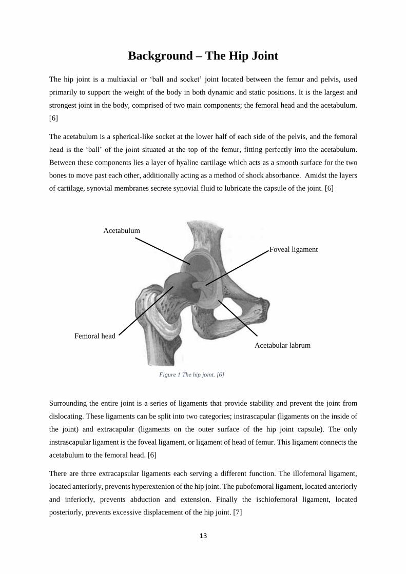
Background – The Hip Joint
The hip joint is a multiaxial or ‘ball and socket’ joint located between the femur and pelvis, used
primarily to support the weight of the body in both dynamic and static positions. It is the largest and
strongest joint in the body, comprised of two main components; the femoral head and the acetabulum.
[6]
The acetabulum is a spherical-like socket at the lower half of each side of the pelvis, and the femoral
head is the ‘ball’ of the joint situated at the top of the femur, fitting perfectly into the acetabulum.
Between these components lies a layer of hyaline cartilage which acts as a smooth surface for the two
bones to move past each other, additionally acting as a method of shock absorbance. Amidst the layers
of cartilage, synovial membranes secrete synovial fluid to lubricate the capsule of the joint. [6]
Surrounding the entire joint is a series of ligaments that provide stability and prevent the joint from
dislocating. These ligaments can be split into two categories; instrascapular (ligaments on the inside of
the joint) and extracapular (ligaments on the outer surface of the hip joint capsule). The only
instrascapular ligament is the foveal ligament, or ligament of head of femur. This ligament connects the
acetabulum to the femoral head. [6]
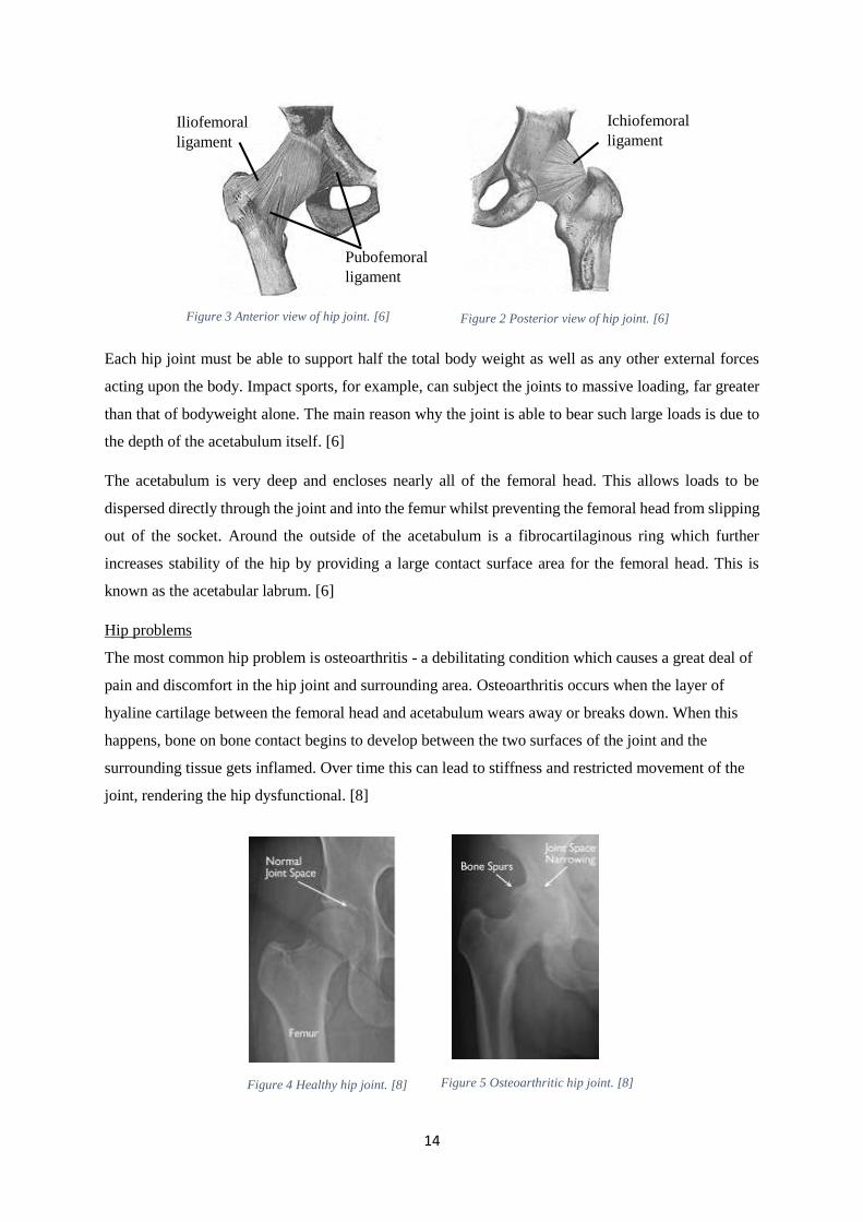
There are three extracapsular ligaments each serving a different function. The illofemoral ligament,
located anteriorly, prevents hyperextenion of the hip joint. The pubofemoral ligament, located anteriorly
and inferiorly, prevents abduction and extension. Finally the ischiofemoral ligament, located
posteriorly, prevents excessive displacement of the hip joint. [7]
Femoral head
Foveal ligament
Acetabulum
Acetabular labrum
Figure 1 The hip joint. [6]
14
Each hip joint must be able to support half the total body weight as well as any other external forces
acting upon the body. Impact sports, for example, can subject the joints to massive loading, far greater
than that of bodyweight alone. The main reason why the joint is able to bear such large loads is due to
the depth of the acetabulum itself. [6]
The acetabulum is very deep and encloses nearly all of the femoral head. This allows loads to be
dispersed directly through the joint and into the femur whilst preventing the femoral head from slipping
out of the socket. Around the outside of the acetabulum is a fibrocartilaginous ring which further
increases stability of the hip by providing a large contact surface area for the femoral head. This is
known as the acetabular labrum. [6]
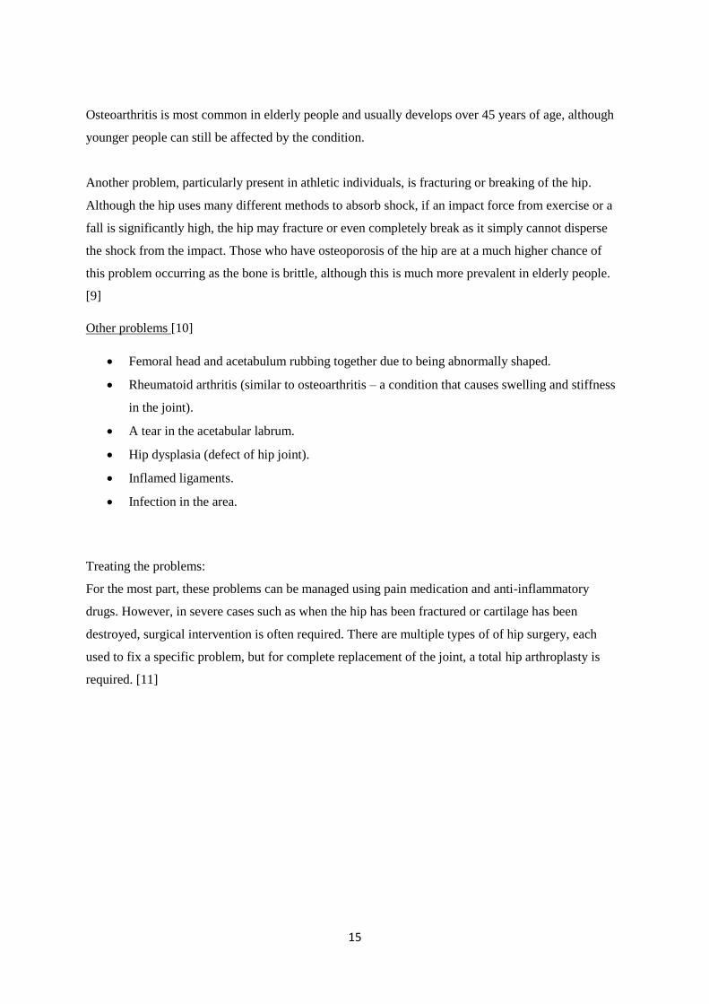
Hip problems
The most common hip problem is osteoarthritis - a debilitating condition which causes a great deal of
pain and discomfort in the hip joint and surrounding area. Osteoarthritis occurs when the layer of
hyaline cartilage between the femoral head and acetabulum wears away or breaks down. When this
happens, bone on bone contact begins to develop between the two surfaces of the joint and the
surrounding tissue gets inflamed. Over time this can lead to stiffness and restricted movement of the
joint, rendering the hip dysfunctional. [8]
Iliofemoral
ligament
Pubofemoral
ligament
Ichiofemoral
ligament
Figure 3 Anterior view of hip joint. [6] Figure 2 Posterior view of hip joint. [6]
Figure 4 Healthy hip joint. [8] Figure 5 Osteoarthritic hip joint. [8]
15
Osteoarthritis is most common in elderly people and usually develops over 45 years of age, although
younger people can still be affected by the condition.
Another problem, particularly present in athletic individuals, is fracturing or breaking of the hip.
Although the hip uses many different methods to absorb shock, if an impact force from exercise or a
fall is significantly high, the hip may fracture or even completely break as it simply cannot disperse
the shock from the impact. Those who have osteoporosis of the hip are at a much higher chance of
this problem occurring as the bone is brittle, although this is much more prevalent in elderly people.
[9]
Other problems [10]
Femoral head and acetabulum rubbing together due to being abnormally shaped.
Rheumatoid arthritis (similar to osteoarthritis – a condition that causes swelling and stiffness
in the joint).
A tear in the acetabular labrum.
Hip dysplasia (defect of hip joint).
Inflamed ligaments.
Infection in the area.
Treating the problems:
For the most part, these problems can be managed using pain medication and anti-inflammatory
drugs. However, in severe cases such as when the hip has been fractured or cartilage has been
destroyed, surgical intervention is often required. There are multiple types of of hip surgery, each
used to fix a specific problem, but for complete replacement of the joint, a total hip arthroplasty is
required. [11]
16
History of Hip Arthroplasty
Arthroplasty as we know it has been around for over 100 years. The earliest recorded attempts at hip
replacement originated from Germany in 1891, where Professor Themistocles Glück proposed the use
of ivory to replace worn femoral heads that had been damaged by tuberculosis [12]. Since then, various
surgeons have contributed to the development of techniques and components used in THA, but none
are as renowned as Sir John Charnley. Charnley, a surgeon at the Manchester Royal Institution,
revolutionised the hip replacement surgery method through optimisation of the components and
decreasing infection from surgery. His techniques and knowledge of the subject have been taught
worldwide to many different nationalities of surgeons, and are still being taught to this day. [13]
Charnley’s prosthesis was based on a low friction design that reduced wear between the femoral head
and acetabulum of the prosthesis. Previously, surgeons had used large femoral heads, with poor long-
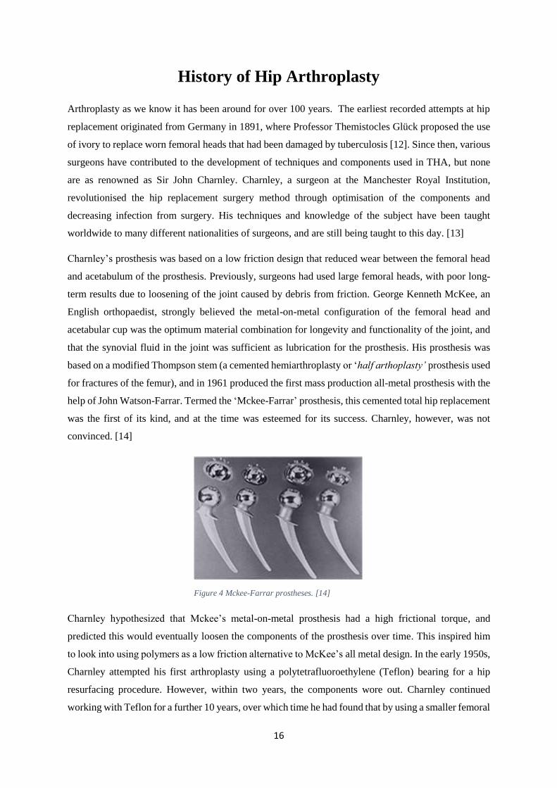
term results due to loosening of the joint caused by debris from friction. George Kenneth McKee, an
English orthopaedist, strongly believed the metal-on-metal configuration of the femoral head and
acetabular cup was the optimum material combination for longevity and functionality of the joint, and
that the synovial fluid in the joint was sufficient as lubrication for the prosthesis. His prosthesis was
based on a modified Thompson stem (a cemented hemiarthroplasty or ‘half arthoplasty’ prosthesis used
for fractures of the femur), and in 1961 produced the first mass production all-metal prosthesis with the
help of John Watson-Farrar. Termed the ‘Mckee-Farrar’ prosthesis, this cemented total hip replacement
was the first of its kind, and at the time was esteemed for its success. Charnley, however, was not
convinced. [14]
Charnley hypothesized that Mckee’s metal-on-metal prosthesis had a high frictional torque, and
predicted this would eventually loosen the components of the prosthesis over time. This inspired him
to look into using polymers as a low friction alternative to McKee’s all metal design. In the early 1950s,
Charnley attempted his first arthroplasty using a polytetrafluoroethylene (Teflon) bearing for a hip
resurfacing procedure. However, within two years, the components wore out. Charnley continued
working with Teflon for a further 10 years, over which time he had found that by using a smaller femoral
Figure 4 Mckee-Farrar prostheses. [14]
17
head there was less surface area for friction to occur in the joint, thus he could minimise the wear rate
of the prosthesis [14]. From the years 1958-1962 he fitted several hundred patients with different
diameter femoral heads, and found moderate success using a diameter of 22.225mm [15]. Nonetheless,
the unsatisfactory wear rates of Teflon were still prevalent, and so this presented him with a problem:
to find a material which not only has a low coefficient of friction, but is hard wearing and durable.
The breakthrough Charnley was looking for came that same year, when his assistant at the time, Harry
Craven, began experimenting with a material he had acquired from a sales technician – High Density
Polyethylene.
“John [Charnley] was going away to Zurich, I think it was, for about three weeks, and he came in and
said, ‘What are you testing?’ I replied, ‘Polyethylene’. ‘Throw the bloody stuff away,’ he said, ‘it’s no
good’. Anyway, I carried on testing it, and when he came back he asked what I was testing and I said,
‘The stuff you told me to throw away’. He asked for my graph, because I did a graph of everything I
did. ‘Well’, I said, ‘there’s your graph, a straight line all around the room and, from my figures, I have
calculated that it would last 70 years’.”
-Harry Craven on his first conversation with John Charnley about HDPE. [16]
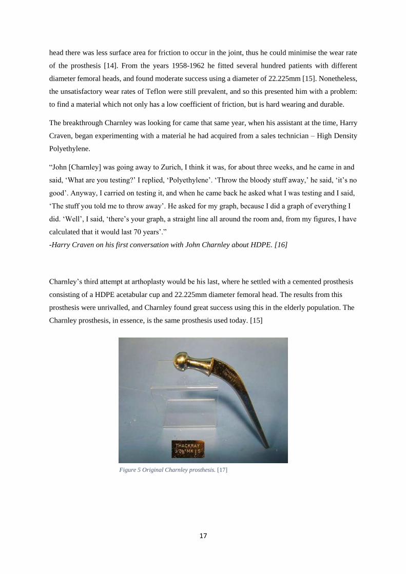
Charnley’s third attempt at arthoplasty would be his last, where he settled with a cemented prosthesis
consisting of a HDPE acetabular cup and 22.225mm diameter femoral head. The results from this
prosthesis were unrivalled, and Charnley found great success using this in the elderly population. The
Charnley prosthesis, in essence, is the same prosthesis used today. [15]
Figure 5 Original Charnley prosthesis. [17]
18
Figure 6 Cross section of cemented stem in femur. [18]
Modern Day Hip Arthroplasty
Today’s prostheses are designed and manufactured to suit each patient’s specific needs. Produced in a
multitude of sizes and custom dimensions, prostheses are sold in three main categories; cemented,
uncemented, and hybrid.
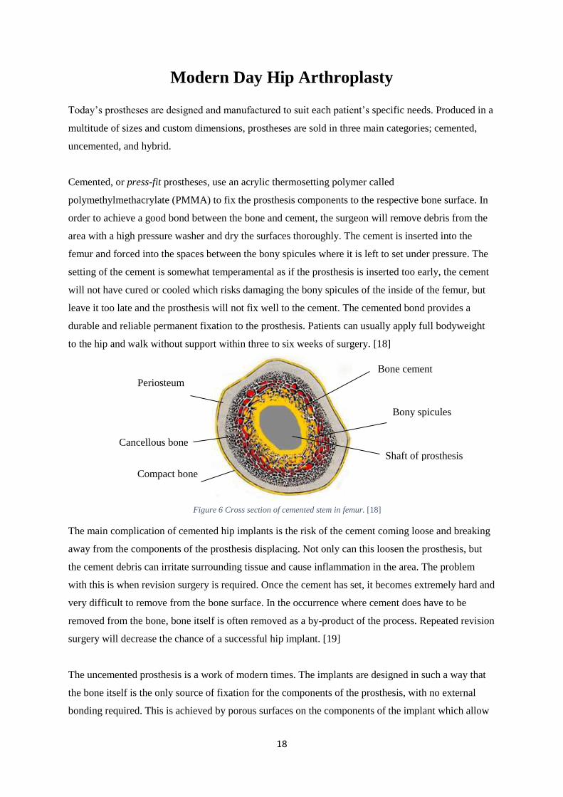
Cemented, or press-fit prostheses, use an acrylic thermosetting polymer called
polymethylmethacrylate (PMMA) to fix the prosthesis components to the respective bone surface. In
order to achieve a good bond between the bone and cement, the surgeon will remove debris from the
area with a high pressure washer and dry the surfaces thoroughly. The cement is inserted into the
femur and forced into the spaces between the bony spicules where it is left to set under pressure. The
setting of the cement is somewhat temperamental as if the prosthesis is inserted too early, the cement
will not have cured or cooled which risks damaging the bony spicules of the inside of the femur, but
leave it too late and the prosthesis will not fix well to the cement. The cemented bond provides a
durable and reliable permanent fixation to the prosthesis. Patients can usually apply full bodyweight
to the hip and walk without support within three to six weeks of surgery. [18]
The main complication of cemented hip implants is the risk of the cement coming loose and breaking
away from the components of the prosthesis displacing. Not only can this loosen the prosthesis, but
the cement debris can irritate surrounding tissue and cause inflammation in the area. The problem
with this is when revision surgery is required. Once the cement has set, it becomes extremely hard and
very difficult to remove from the bone surface. In the occurrence where cement does have to be
removed from the bone, bone itself is often removed as a by-product of the process. Repeated revision
surgery will decrease the chance of a successful hip implant. [19]
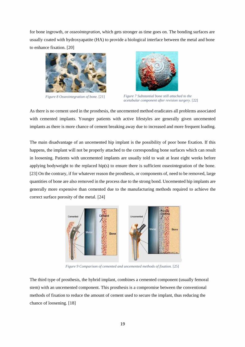
The uncemented prosthesis is a work of modern times. The implants are designed in such a way that
the bone itself is the only source of fixation for the components of the prosthesis, with no external
bonding required. This is achieved by porous surfaces on the components of the implant which allow
Periosteum
Cancellous bone
Compact bone
Bone cement
Bony spicules
Shaft of prosthesis
19
for bone ingrowth, or osseointegration, which gets stronger as time goes on. The bonding surfaces are
usually coated with hydroxyapatite (HA) to provide a biological interface between the metal and bone
to enhance fixation. [20]
As there is no cement used in the prosthesis, the uncemented method eradicates all problems associated
with cemented implants. Younger patients with active lifestyles are generally given uncemented
implants as there is more chance of cement breaking away due to increased and more frequent loading.
The main disadvantage of an uncemented hip implant is the possibility of poor bone fixation. If this
happens, the implant will not be properly attached to the corresponding bone surfaces which can result
in loosening. Patients with uncemented implants are usually told to wait at least eight weeks before
applying bodyweight to the replaced hip(s) to ensure there is sufficient osseointegration of the bone.
[23] On the contrary, if for whatever reason the prosthesis, or components of, need to be removed, large
quantities of bone are also removed in the process due to the strong bond. Uncemented hip implants are
generally more expensive than cemented due to the manufacturing methods required to achieve the
correct surface porosity of the metal. [24]
The third type of prosthesis, the hybrid implant, combines a cemented component (usually femoral
stem) with an uncemented component. This prosthesis is a compromise between the conventional
methods of fixation to reduce the amount of cement used to secure the implant, thus reducing the
chance of loosening. [18]
Figure 8 Osseointegration of bone. [21] Figure 7 Substantial bone still attached to the
acetabular component after revision surgery. [22]
Figure 9 Comparison of cemented and uncemented methods of fixation. [25]
20
Variations of Prostheses
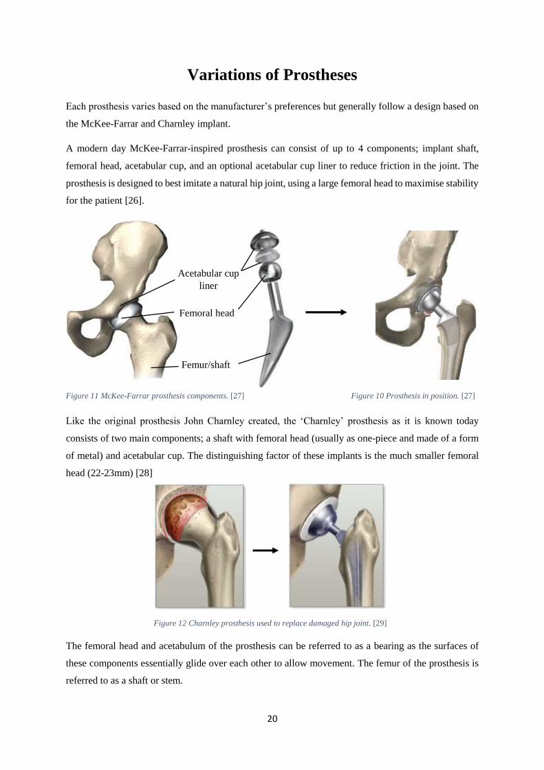
Each prosthesis varies based on the manufacturer’s preferences but generally follow a design based on
the McKee-Farrar and Charnley implant.
A modern day McKee-Farrar-inspired prosthesis can consist of up to 4 components; implant shaft,
femoral head, acetabular cup, and an optional acetabular cup liner to reduce friction in the joint. The
prosthesis is designed to best imitate a natural hip joint, using a large femoral head to maximise stability
for the patient [26].
Like the original prosthesis John Charnley created, the ‘Charnley’ prosthesis as it is known today
consists of two main components; a shaft with femoral head (usually as one-piece and made of a form
of metal) and acetabular cup. The distinguishing factor of these implants is the much smaller femoral
head (22-23mm) [28]
The femoral head and acetabulum of the prosthesis can be referred to as a bearing as the surfaces of
these components essentially glide over each other to allow movement. The femur of the prosthesis is
referred to as a shaft or stem.
Acetabular cup
liner
Femur/shaft
Femoral head
Figure 11 McKee-Farrar prosthesis components. [27] Figure 10 Prosthesis in position. [27]
Figure 12 Charnley prosthesis used to replace damaged hip joint. [29]
21
Materials of Components
Stem
The main requirements of a material for the stem of a hip prosthesis are high strength, high hardness
and high toughness. Metals are the most suitable material for this application as they have higher values
of Young’s Modulus and are ductile, meaning they have a good resistance to fatigue and will yield
before breaking. In the case of ceramics or other materials with lower ductility, sudden breaking will
occur under loading with no warning or anticipation of it happening. Plastics are also unsuitable to be
used for implant stems due to their low resistance to fatigue. [30]
For a long time, the go-to choice for the material of the implant stem was stainless steel. In the early
days of arthroplasty, stainless steel was regarded as the best material choice due to its high resistance
to corrosion, hardness and strength. However, as stainless steel is an alloy of nickel, it poses the risk of
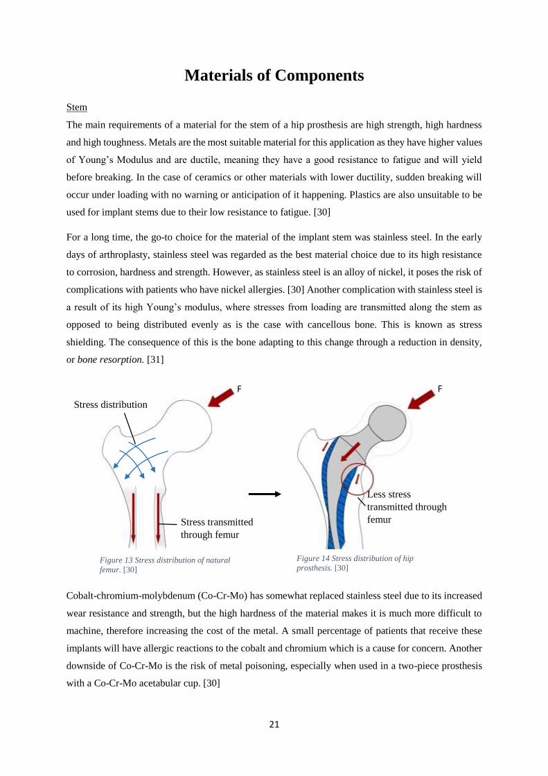
complications with patients who have nickel allergies. [30] Another complication with stainless steel is
a result of its high Young’s modulus, where stresses from loading are transmitted along the stem as
opposed to being distributed evenly as is the case with cancellous bone. This is known as stress
shielding. The consequence of this is the bone adapting to this change through a reduction in density,
or bone resorption. [31]
Cobalt-chromium-molybdenum (Co-Cr-Mo) has somewhat replaced stainless steel due to its increased
wear resistance and strength, but the high hardness of the material makes it is much more difficult to
machine, therefore increasing the cost of the metal. A small percentage of patients that receive these
implants will have allergic reactions to the cobalt and chromium which is a cause for concern. Another
downside of Co-Cr-Mo is the risk of metal poisoning, especially when used in a two-piece prosthesis
with a Co-Cr-Mo acetabular cup. [30]
Stress distribution
Stress transmitted
through femur
Less stress
transmitted through
femur
F F
Figure 13 Stress distribution of natural
femur. [30]
Figure 14 Stress distribution of hip
prosthesis. [30]
22
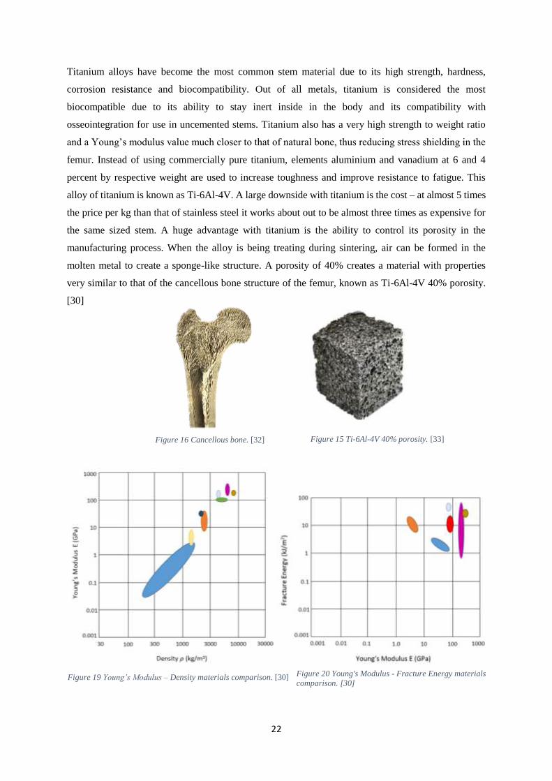
Titanium alloys have become the most common stem material due to its high strength, hardness,
corrosion resistance and biocompatibility. Out of all metals, titanium is considered the most
biocompatible due to its ability to stay inert inside in the body and its compatibility with
osseointegration for use in uncemented stems. Titanium also has a very high strength to weight ratio
and a Young’s modulus value much closer to that of natural bone, thus reducing stress shielding in the
femur. Instead of using commercially pure titanium, elements aluminium and vanadium at 6 and 4
percent by respective weight are used to increase toughness and improve resistance to fatigue. This
alloy of titanium is known as Ti-6Al-4V. A large downside with titanium is the cost – at almost 5 times
the price per kg than that of stainless steel it works about out to be almost three times as expensive for
the same sized stem. A huge advantage with titanium is the ability to control its porosity in the
manufacturing process. When the alloy is being treating during sintering, air can be formed in the
molten metal to create a sponge-like structure. A porosity of 40% creates a material with properties
very similar to that of the cancellous bone structure of the femur, known as Ti-6Al-4V 40% porosity.
[30]
Figure 16 Cancellous bone. [32] Figure 15 Ti-6Al-4V 40% porosity. [33]
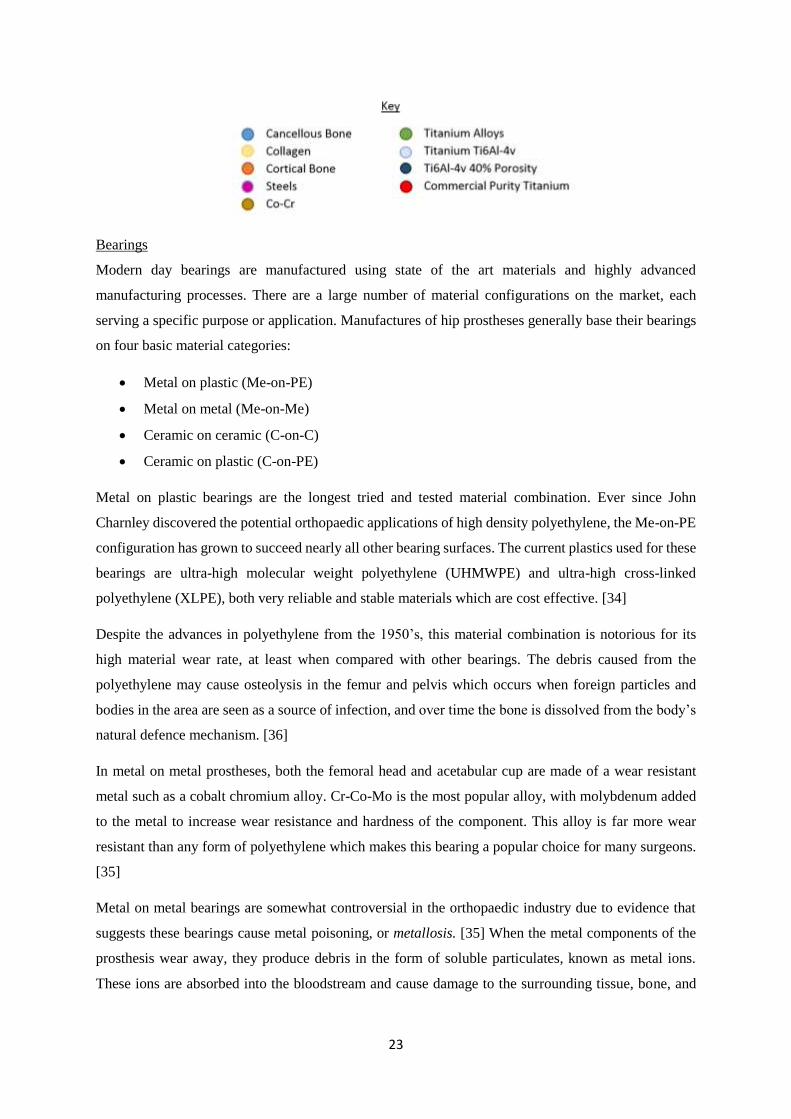
Figure 19 Young’s Modulus – Density materials comparison. [30] Figure 20 Young's Modulus - Fracture Energy materials
comparison. [30]
23
Bearings
Modern day bearings are manufactured using state of the art materials and highly advanced
manufacturing processes. There are a large number of material configurations on the market, each
serving a specific purpose or application. Manufactures of hip prostheses generally base their bearings
on four basic material categories:
Metal on plastic (Me-on-PE)
Metal on metal (Me-on-Me)
Ceramic on ceramic (C-on-C)
Ceramic on plastic (C-on-PE)
Metal on plastic bearings are the longest tried and tested material combination. Ever since John
Charnley discovered the potential orthopaedic applications of high density polyethylene, the Me-on-PE
configuration has grown to succeed nearly all other bearing surfaces. The current plastics used for these
bearings are ultra-high molecular weight polyethylene (UHMWPE) and ultra-high cross-linked
polyethylene (XLPE), both very reliable and stable materials which are cost effective. [34]
Despite the advances in polyethylene from the 1950’s, this material combination is notorious for its
high material wear rate, at least when compared with other bearings. The debris caused from the
polyethylene may cause osteolysis in the femur and pelvis which occurs when foreign particles and
bodies in the area are seen as a source of infection, and over time the bone is dissolved from the body’s
natural defence mechanism. [36]
In metal on metal prostheses, both the femoral head and acetabular cup are made of a wear resistant
metal such as a cobalt chromium alloy. Cr-Co-Mo is the most popular alloy, with molybdenum added
to the metal to increase wear resistance and hardness of the component. This alloy is far more wear
resistant than any form of polyethylene which makes this bearing a popular choice for many surgeons.
[35]
Metal on metal bearings are somewhat controversial in the orthopaedic industry due to evidence that
suggests these bearings cause metal poisoning, or metallosis. [35] When the metal components of the
prosthesis wear away, they produce debris in the form of soluble particulates, known as metal ions.
These ions are absorbed into the bloodstream and cause damage to the surrounding tissue, bone, and
24
nervous system. Over time this can lead to deterioration of the hip and ultimately implant failure. This
is especially prevalent in the case of large femoral heads with increased wear rate. [37]
One example of how catastrophic the effects of metallosis can be in metal on metal implants is the 2010
DePuy recall. On the 24th of August, 2010, the orthopaedic company DePuy issued a voluntary recall
of two of their most popular metal on metal implants; the ASR™ XL Acetabular Hip System and the
ASR™ Hip Resurfacing System. [38] The company received approximately 300 complaints from
patients who had been given ASR implants since 2008, and data from the UK joint registry in 2010
revealed that approximately 13% of all ASR patients had undergone revision surgery within 5 years of
their operation. The main complications patients experienced were loosening components, metal
sensitivity, pain, and increased metal ions in the blood, resulting in nerve damage, necrosis and tissue
damage. There are currently lawsuits ongoing between DePuy and the effected people involved. [39]
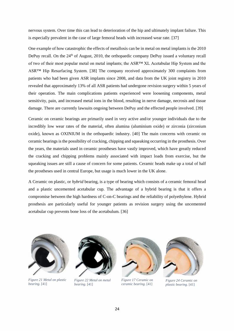
Ceramic on ceramic bearings are primarily used in very active and/or younger individuals due to the
incredibly low wear rates of the material, often alumina (aluminium oxide) or zirconia (zirconium
oxide), known as OXINIUM in the orthopaedic industry. [40] The main concerns with ceramic on
ceramic bearings is the possibility of cracking, chipping and squeaking occurring in the prosthesis. Over
the years, the materials used in ceramic prostheses have vastly improved, which have greatly reduced
the cracking and chipping problems mainly associated with impact loads from exercise, but the
squeaking issues are still a cause of concern for some patients. Ceramic heads make up a total of half
the prostheses used in central Europe, but usage is much lower in the UK alone.
A Ceramic on plastic, or hybrid bearing, is a type of bearing which consists of a ceramic femoral head
and a plastic uncemented acetabular cup. The advantage of a hybrid bearing is that it offers a
compromise between the high hardness of C-on-C bearings and the reliability of polyethylene. Hybrid
prosthesis are particularly useful for younger patients as revision surgery using the uncemented
acetabular cup prevents bone loss of the acetabulum. [36]
Figure 21 Metal on plastic
bearing. [41] Figure 24 Ceramic on
plastic bearing. [41] Figure 22 Metal on metal
bearing. [41]
Figure 17 Ceramic on
ceramic bearing. [41]
25
Table 1 Summary of bearing materials.
Table 2 Properties of most common prosthesis materials.
Prosthesis Advantages Disadvantages
(Me-on-PE) -Renowned for its high
reliability.
-Cost effective.
-Most widely available
overall.
-The debris from the
polyethylene can lead to aseptic
loosening of the joint.
(Me-on-Me) -Durable and strong.
-Reduced wear than metal on
polyethylene.
-Danger of metallosis.
-Somewhat bad reputation in
the orthopaedic community.
(C-on-C) -Lowest friction bearing with
minimal wear and debris
-Theoretically posing the
longest lifespan.
-Improved lubrication.
-Most expensive out of all the
prostheses.
-Possibility of cracking and
fracturing due to brittle nature
of material.
-Squeaking may occur.
(C-on-PE) -Useful in younger patients
that may require revision
surgery in the future.
-Less wear rate than metal on
polyethylene.
-Very few trials performed on
this bearing.
-Lack of trials to support
theoretical advantages.
Component Material Property
Young’s
Modulus
(GPa)
Poisson’s
Ratio
Shear
Modulus
(GPa)
Mass
Density
(𝑘𝑔/𝑚3)
Tensile
Strength
(MPa)
Yield
Strength
(MPa)
Stem Stainless
Steel [42]
200 0.29 86 8000 505 215
Titanium Ti-
6Al-4V [43]
113.8 0.342 44 4430 950 880
Acetabular
cup
UHMWPE
[44]
0.7 0.46 0.32 926 48 21
Co-Cr-Mo
[45]
201 0.38 68 8430 758 345
Zirconia [46] 205 0.31 78.2 5740 450 276
0.1-0.5mm/year
0.0001mm/year
0.01mm/year
0.1mm/year
Figure 18 Comparison of wear rates for bearing materials. [36]
26
Life After Surgery
For the most part, life after a total hip replacement is very much the same as life prior to encountering
pain and restriction of the natural hip joint. The surgeon and/or orthopaedic unit that perform the
operation will often issue limitations and guidelines for the patient to follow as a method of reducing
complications after surgery.
One complication encountered by patients is subluxation and dislocation of the prosthesis. [47] If the
hip is bent past a certain angle, then depending on the size of the femoral head and acetabular cup, the
head may partly or completely exit away from the pelvis. Not only does this render the prosthesis
completely useless, but the force concentrations at the point of dislocation can damage the components.
As a result of this, patients are advised to not bend their leg(s) past a certain point to ensure the prosthesis
never approaches the critical angle of dislocation. [48]
A second complication is the danger of fracturing and cracking of the prosthesis components as a result
of high impact loads. High impact loads occur in situations where the normal reaction forces of the
patient’s bodyweight are multiplied either by an accident or a form of injury from exercise. Younger
patients who play sports or are physically active are at the highest risk of this problem occurring due to
the increased chance of being involved in such impacts. Exercises such as weight training, rugby, and
even jogging are all excellent examples of high impact sports. [49]
The third complication, again primarily concerning younger patients, is the reduced life of the prosthesis
due to increased wear rates of the component(s). This problem is a result of continuous, repetitive
movement of the prosthesis for long periods of time. An example an exercise which could cause this
problem is cycling, where the hip undergoes tens of thousands of cycles of movement in a relatively
short space of time. [49]
27
Method
1. Create a free body diagram of the body in one-legged position to calculate resultant force on
hip joint and angle at which it acts.
2. Research the peak loads of different exercises and activities and summarise these as resultant
force equations in terms of bodyweight.
3. Use data from a UK census or anthropometrics survery to calculate the resultant force of the
hip for a male of average weight when exercising.
4. Determine the angle the femur extends when the body is exercising.
5. Produce a scale model of a prosthesis using SolidWorks using dimensions of components
from reputable orthopaedic implant manufacturers.
6. Configure the models for a simulation using the peak forces of exercises and the angles at
which the femur is extended.
7. Converge one of the models to determine the optimum mesh size for the simulation.
8. Run a series of simulations using different materials for the femoral stem and acetabular cup.
9. Record relevent plots and record the results in a series of tables to compare data.
10. Produce graphs of the relationship between materials of components and relevent plots of the
simulation.
28
Methodology
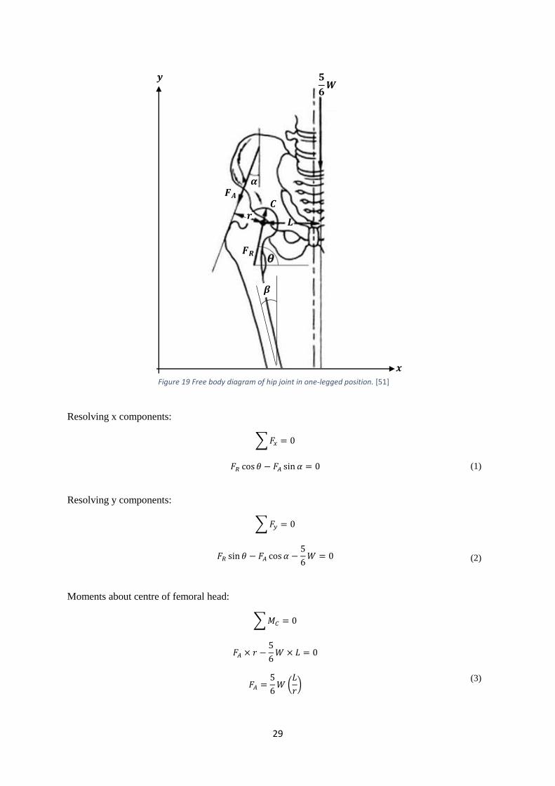
Forces Acting on the Hip Joint
To explore the effects of exercise on the the prostheses components, biomechanical research was first
made into how exercise effects the natural hip joint. By studying the hip at at stationary points of
different stances, the resultant force and the angle at which it acts can be determined.
Two-legged stance:
When the body is stationary, it can be said that it is in a two-legged stance where each leg constitutes
one sixth of the total bodyweight to make a combined total of two sixths of the total bodyweight, or
1/3W. The resultant force of the bodyweight, 2/3W, is equally distributed across each hip. Therefore it
can be said that each hip carries 1/3W, with little or no muscle contraction used to support this load.
[50]
One-legged stance:
To calculate the forces acting on the hip in a two legged stance, a free body diagram can be used.
Firstly, because only one leg is supported by the ground, it can be said that the total weight acting on
the hip is five sixths times the bodyweight, or 5/6W, at a perpendicular distance 𝐿 from the centre of
the femoral head, 𝐶. This force is balanced by muscle contractions in the surrounding area of the hip,
which stabilizes the pelvis by counteracting the leverage given by the bodyweight. [50]
For simplicity, the forces of these muscle contractions can be represented by a single force, known as
the net abductor muscle force 𝐹𝐴, which acts towards the gluteus muscles to the rear of the pelvis, at a
perpendicular distance 𝑟 from 𝐶. The angle at which this force acts from the vertical can be
represented by 𝛼. A normal value for this angle is 20°. [50]
The total force acting on the hip, or resultant force, can be expressed as a single component that acts
between the femoral head and the acetabulum at angle 𝜃 to the ground. This force, 𝐹𝑅, is proportional
the ratio of 𝐿 over 𝑟, which is usually a value of 2.5. Angle 𝛽 is known as the Q-angle of the
quadriceps of the femur and ranges from 10-14° in males and 15-17° in females as a result of
difference in hip width. [51]
29
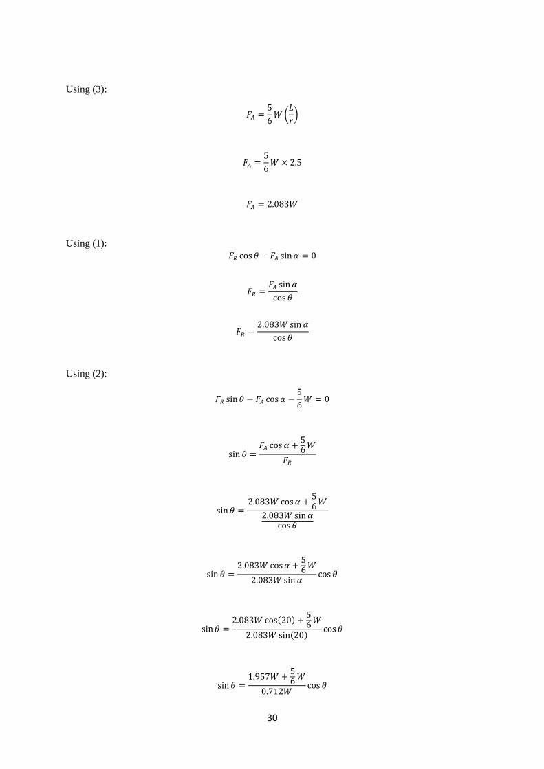
Resolving x components:
∑ 𝐹𝑥 = 0
𝐹𝑅 cos 𝜃 − 𝐹𝐴 sin 𝛼 = 0
(1)
Resolving y components:
∑ 𝐹𝑦 = 0
𝐹𝑅 sin 𝜃 − 𝐹𝐴 cos 𝛼 −
5
6𝑊 = 0 (2)
Moments about centre of femoral head:
∑ 𝑀𝐶 = 0
𝐹𝐴 × 𝑟 −
5
6𝑊 × 𝐿 = 0
𝐹𝐴 =
5
6𝑊 (
𝐿
𝑟)
(3)
𝟓
𝟔𝑾
𝒓 𝑳
𝑭𝑨
𝑭𝑹
𝜶
𝒚
𝒙
𝑪
𝜷
Figure 19 Free body diagram of hip joint in one-legged position. [51]
30
Using (3):
𝐹𝐴 =5
6𝑊 (
𝐿
𝑟)
𝐹𝐴 =5
6𝑊 × 2.5
𝐹𝐴 = 2.083𝑊
Using (1): 𝐹𝑅 cos 𝜃 − 𝐹𝐴 sin 𝛼 = 0
𝐹𝑅 =𝐹𝐴 sin 𝛼
cos 𝜃
𝐹𝑅 =2.083𝑊 sin 𝛼
cos 𝜃
Using (2):
𝐹𝑅 sin 𝜃 − 𝐹𝐴 cos 𝛼 −5
6𝑊 = 0
sin 𝜃 =𝐹𝐴 cos 𝛼 +
56
𝑊
𝐹𝑅
sin 𝜃 =2.083𝑊 cos 𝛼 +
56
𝑊
2.083𝑊 sin 𝛼cos 𝜃
sin 𝜃 =2.083𝑊 cos 𝛼 +
56
𝑊
2.083𝑊 sin 𝛼cos 𝜃
sin 𝜃 =2.083𝑊 cos(20) +
56
𝑊
2.083𝑊 sin(20)cos 𝜃
sin 𝜃 =1.957𝑊 +
56
𝑊
0.712𝑊cos 𝜃
31
Figure 20 Visualisation of forces acting on
body when walking. [52]
sin 𝜃 = 3.917 cos 𝜃
∴ 𝜃 = tan−1(3.917) = 75.7°
Using (1):
𝐹𝑅 =2.083𝑊 sin 𝛼
cos 𝜃
𝐹𝑅 =2.083𝑊 sin(20)
cos(75.7)
𝐹𝑅 =0.712𝑊
0.247
𝑭𝑹 = 𝟐. 𝟖𝟖𝟎𝑾
2.880W
2.083W
𝟓
𝟔𝑾
32
Effects of Exercise on Natural Hip
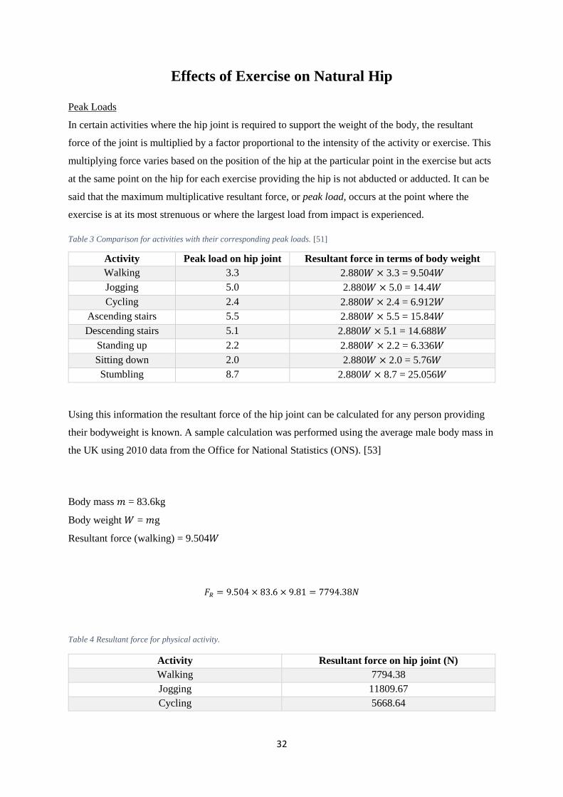
Peak Loads
In certain activities where the hip joint is required to support the weight of the body, the resultant
force of the joint is multiplied by a factor proportional to the intensity of the activity or exercise. This
multiplying force varies based on the position of the hip at the particular point in the exercise but acts
at the same point on the hip for each exercise providing the hip is not abducted or adducted. It can be
said that the maximum multiplicative resultant force, or peak load, occurs at the point where the
exercise is at its most strenuous or where the largest load from impact is experienced.
Table 3 Comparison for activities with their corresponding peak loads. [51]
Using this information the resultant force of the hip joint can be calculated for any person providing
their bodyweight is known. A sample calculation was performed using the average male body mass in
the UK using 2010 data from the Office for National Statistics (ONS). [53]
Body mass 𝑚 = 83.6kg
Body weight 𝑊 = 𝑚g
Resultant force (walking) = 9.504𝑊
𝐹𝑅 = 9.504 × 83.6 × 9.81 = 7794.38𝑁
Table 4 Resultant force for physical activity.
Activity Resultant force on hip joint (N)
Walking 7794.38
Jogging 11809.67
Cycling 5668.64
Activity Peak load on hip joint Resultant force in terms of body weight
Walking 3.3 2.880𝑊 × 3.3 = 9.504𝑊
Jogging 5.0 2.880𝑊 × 5.0 = 14.4𝑊
Cycling 2.4 2.880𝑊 × 2.4 = 6.912𝑊
Ascending stairs 5.5 2.880𝑊 × 5.5 = 15.84𝑊
Descending stairs 5.1 2.880𝑊 × 5.1 = 14.688𝑊
Standing up 2.2 2.880𝑊 × 2.2 = 6.336𝑊
Sitting down 2.0 2.880𝑊 × 2.0 = 5.76𝑊
Stumbling 8.7 2.880𝑊 × 8.7 = 25.056𝑊
33
Figure 23 Average hip angle during gait analysis using a three dimensional musculoskeletal model (Effect of
hip angle on anterior hip joint force during gait, Lewis CL, Sahrmann SA, Moran DW, 2010.)
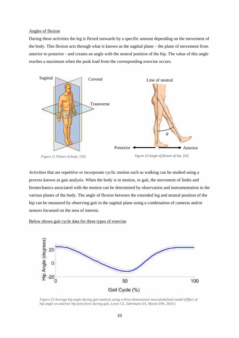
Angles of flexion
During these activities the leg is flexed outwards by a specific amount depending on the movement of
the body. This flexion acts through what is known as the sagittal plane – the plane of movement from
anterior to posterior - and creates an angle with the neutral position of the hip. The value of this angle
reaches a maximum when the peak load from the corresponding exercise occurs.
Activities that are repetitive or incorporate cyclic motion such as walking can be studied using a
process known as gait analysis. When the body is in motion, or gait, the movement of limbs and
biomechanics associated with the motion can be determined by observation and instrumentation in the
various planes of the body. The angle of flexion between the extended leg and neutral position of the
hip can be measured by observing gait in the sagittal plane using a combination of cameras and/or
sensors focussed on the area of interest.
Below shows gait cycle data for three types of exercise
Sagittal Coronal
Transverse
Anterior Posterior
𝜃
Line of neutral
Figure 21 Planes of body. [54] Figure 22 Angle of flexion of hip. [55]
34
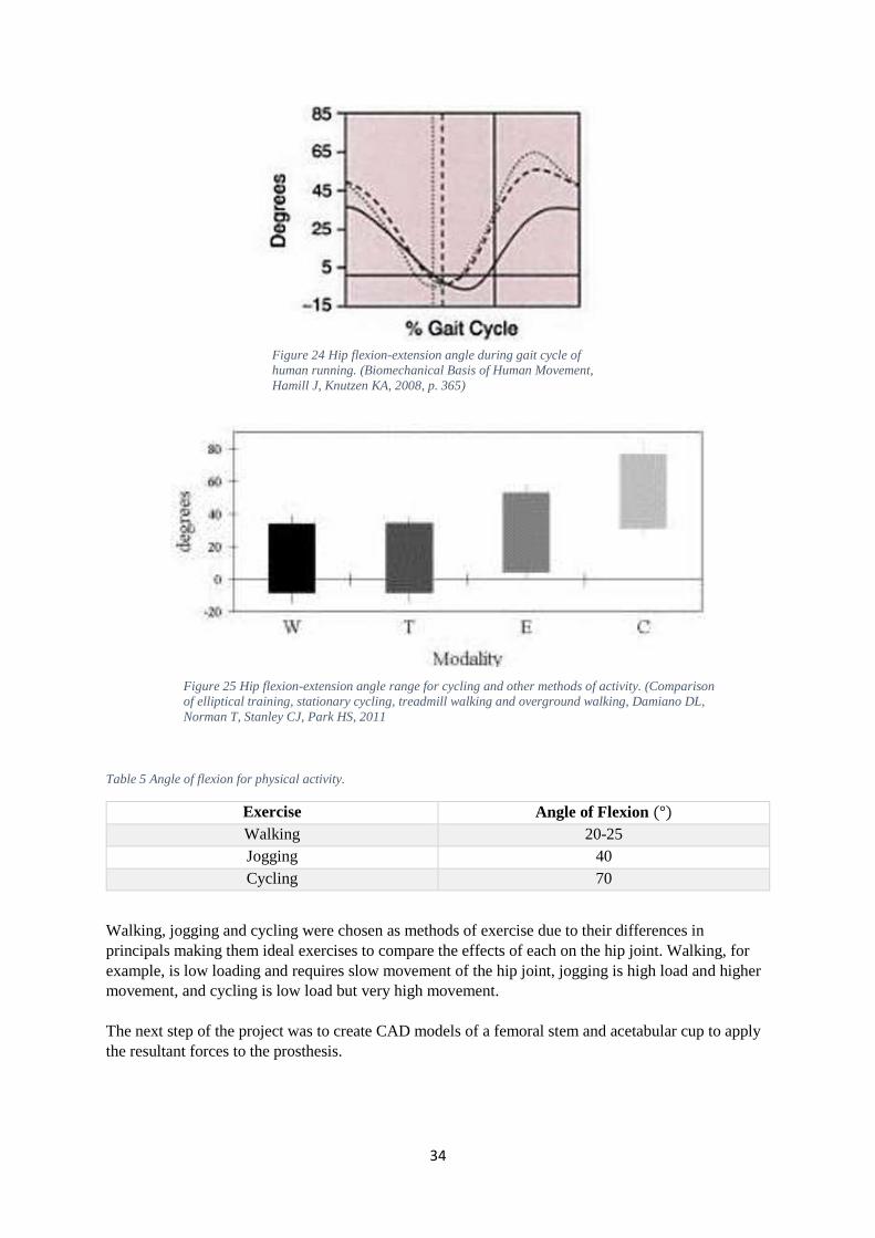
Table 5 Angle of flexion for physical activity.
Exercise Angle of Flexion (°)
Walking 20-25
Jogging 40
Cycling 70
Walking, jogging and cycling were chosen as methods of exercise due to their differences in
principals making them ideal exercises to compare the effects of each on the hip joint. Walking, for
example, is low loading and requires slow movement of the hip joint, jogging is high load and higher
movement, and cycling is low load but very high movement.
The next step of the project was to create CAD models of a femoral stem and acetabular cup to apply
the resultant forces to the prosthesis.
Figure 24 Hip flexion-extension angle during gait cycle of
human running. (Biomechanical Basis of Human Movement,
Hamill J, Knutzen KA, 2008, p. 365)
Figure 25 Hip flexion-extension angle range for cycling and other methods of activity. (Comparison
of elliptical training, stationary cycling, treadmill walking and overground walking, Damiano DL,
Norman T, Stanley CJ, Park HS, 2011
35
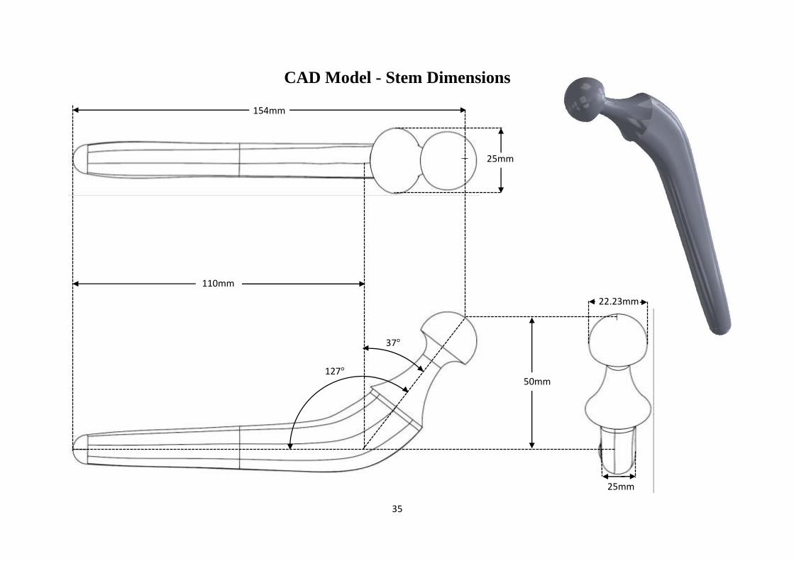
CAD Model - Stem Dimensions
127°
110mm
25mm
22.23mm
37°
25mm
50mm
154mm
36
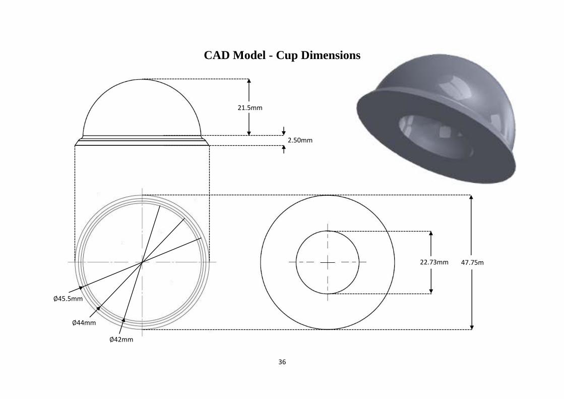
CAD Model - Cup Dimensions
22.73mm
2.50mm
21.5mm
∅44mm
∅42mm
47.75m
m
∅45.5mm
37
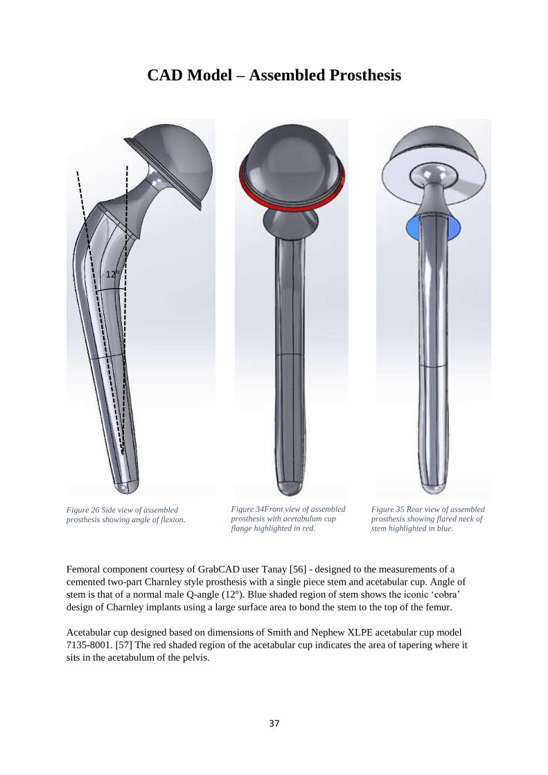
Figure 26 Side view of assembled
prosthesis showing angle of flexion.
CAD Model – Assembled Prosthesis
Femoral component courtesy of GrabCAD user Tanay [56] - designed to the measurements of a
cemented two-part Charnley style prosthesis with a single piece stem and acetabular cup. Angle of
stem is that of a normal male Q-angle (12°). Blue shaded region of stem shows the iconic ‘cobra’
design of Charnley implants using a large surface area to bond the stem to the top of the femur.
Acetabular cup designed based on dimensions of Smith and Nephew XLPE acetabular cup model
7135-8001. [57] The red shaded region of the acetabular cup indicates the area of tapering where it
sits in the acetabulum of the pelvis.
12°
Figure 34Front view of assembled
prosthesis with acetabulum cup
flange highlighted in red.
Figure 35 Rear view of assembled
prosthesis showing flared neck of
stem highlighted in blue.
38
Finite Element Analysis Set-up
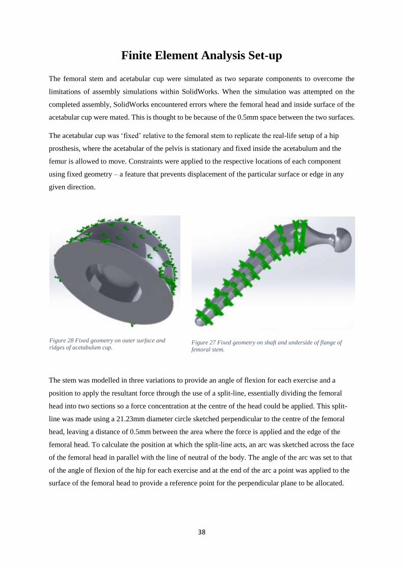
The femoral stem and acetabular cup were simulated as two separate components to overcome the
limitations of assembly simulations within SolidWorks. When the simulation was attempted on the
completed assembly, SolidWorks encountered errors where the femoral head and inside surface of the
acetabular cup were mated. This is thought to be because of the 0.5mm space between the two surfaces.
The acetabular cup was ‘fixed’ relative to the femoral stem to replicate the real-life setup of a hip
prosthesis, where the acetabular of the pelvis is stationary and fixed inside the acetabulum and the
femur is allowed to move. Constraints were applied to the respective locations of each component
using fixed geometry – a feature that prevents displacement of the particular surface or edge in any
given direction.
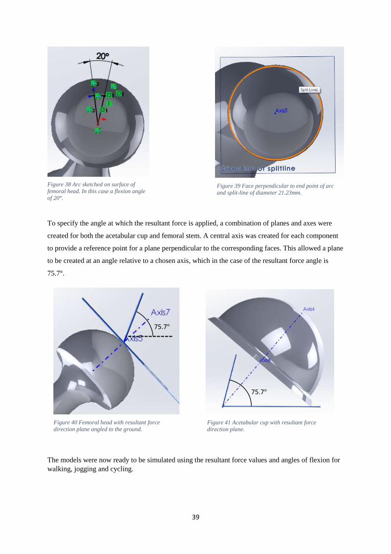
The stem was modelled in three variations to provide an angle of flexion for each exercise and a
position to apply the resultant force through the use of a split-line, essentially dividing the femoral
head into two sections so a force concentration at the centre of the head could be applied. This split-
line was made using a 21.23mm diameter circle sketched perpendicular to the centre of the femoral
head, leaving a distance of 0.5mm between the area where the force is applied and the edge of the
femoral head. To calculate the position at which the split-line acts, an arc was sketched across the face
of the femoral head in parallel with the line of neutral of the body. The angle of the arc was set to that
of the angle of flexion of the hip for each exercise and at the end of the arc a point was applied to the
surface of the femoral head to provide a reference point for the perpendicular plane to be allocated.
Figure 28 Fixed geometry on outer surface and
ridges of acetabulum cup. Figure 27 Fixed geometry on shaft and underside of flange of
femoral stem.
39
Figure 40 Femoral head with resultant force
direction plane angled to the ground.
To specify the angle at which the resultant force is applied, a combination of planes and axes were
created for both the acetabular cup and femoral stem. A central axis was created for each component
to provide a reference point for a plane perpendicular to the corresponding faces. This allowed a plane
to be created at an angle relative to a chosen axis, which in the case of the resultant force angle is
75.7°.
The models were now ready to be simulated using the resultant force values and angles of flexion for
walking, jogging and cycling.
75.7°
75.7°
Figure 38 Arc sketched on surface of
femoral head. In this case a flexion angle
of 20°.
Figure 39 Face perpendicular to end point of arc
and split-line of diameter 21.23mm.
Figure 41 Acetabular cup with resultant force
direction plane.
40
Convergence
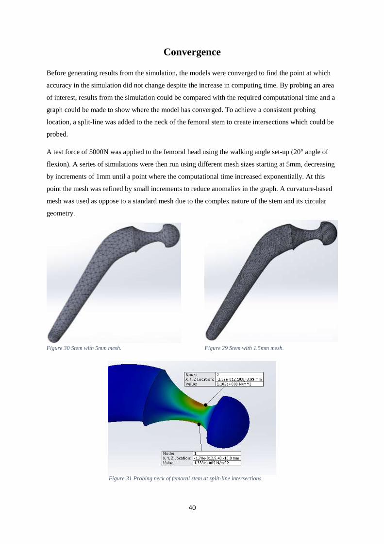
Before generating results from the simulation, the models were converged to find the point at which
accuracy in the simulation did not change despite the increase in computing time. By probing an area
of interest, results from the simulation could be compared with the required computational time and a
graph could be made to show where the model has converged. To achieve a consistent probing
location, a split-line was added to the neck of the femoral stem to create intersections which could be
probed.
A test force of 5000N was applied to the femoral head using the walking angle set-up (20° angle of
flexion). A series of simulations were then run using different mesh sizes starting at 5mm, decreasing
by increments of 1mm until a point where the computational time increased exponentially. At this
point the mesh was refined by small increments to reduce anomalies in the graph. A curvature-based
mesh was used as oppose to a standard mesh due to the complex nature of the stem and its circular
geometry.
Figure 30 Stem with 5mm mesh. Figure 29 Stem with 1.5mm mesh.
Figure 31 Probing neck of femoral stem at split-line intersections.
41
0.00E+00
2.00E+08
4.00E+08
6.00E+08
8.00E+08
1.00E+09
1.20E+09
1.40E+09
1.60E+09
0 50000 100000 150000 200000 250000 300000 350000
von
Mis
es S
tres
s (P
a)
No. of nodes of simulation
Convergence Plot
von Mises stress (Pa) Top of neck von Mises stress (Pa) Bottom of neck
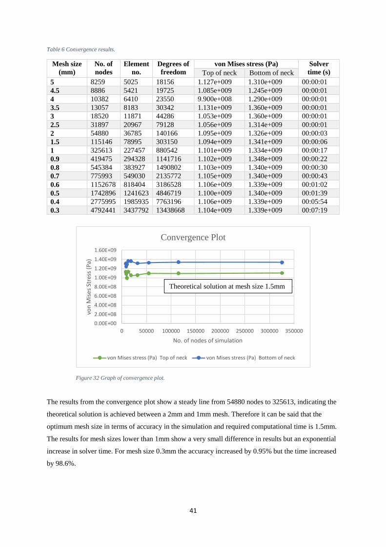
Table 6 Convergence results.
Mesh size
(mm)
No. of
nodes
Element
no.
Degrees of
freedom
von Mises stress (Pa) Solver
time (s) Top of neck Bottom of neck
5 8259 5025 18156 1.127e+009 1.310e+009 00:00:01
4.5 8886 5421 19725 1.085e+009 1.245e+009 00:00:01
4 10382 6410 23550 9.900e+008 1.290e+009 00:00:01
3.5 13057 8183 30342 1.131e+009 1.360e+009 00:00:01
3 18520 11871 44286 1.053e+009 1.360e+009 00:00:01
2.5 31897 20967 79128 1.056e+009 1.314e+009 00:00:01
2 54880 36785 140166 1.095e+009 1.326e+009 00:00:03
1.5 115146 78995 303150 1.094e+009 1.341e+009 00:00:06
1 325613 227457 880542 1.101e+009 1.334e+009 00:00:17
0.9 419475 294328 1141716 1.102e+009 1.348e+009 00:00:22
0.8 545384 383927 1490802 1.103e+009 1.340e+009 00:00:30
0.7 775993 549030 2135772 1.105e+009 1.340e+009 00:00:43
0.6 1152678 818404 3186528 1.106e+009 1.339e+009 00:01:02
0.5 1742896 1241623 4846719 1.100e+009 1.340e+009 00:01:39
0.4 2775995 1985935 7763196 1.106e+009 1.339e+009 00:05:54
0.3 4792441 3437792 13438668 1.104e+009 1.339e+009 00:07:19
The results from the convergence plot show a steady line from 54880 nodes to 325613, indicating the
theoretical solution is achieved between a 2mm and 1mm mesh. Therefore it can be said that the
optimum mesh size in terms of accuracy in the simulation and required computational time is 1.5mm.
The results for mesh sizes lower than 1mm show a very small difference in results but an exponential
increase in solver time. For mesh size 0.3mm the accuracy increased by 0.95% but the time increased
by 98.6%.
Theoretical solution at mesh size 1.5mm
Figure 32 Graph of convergence plot.
42
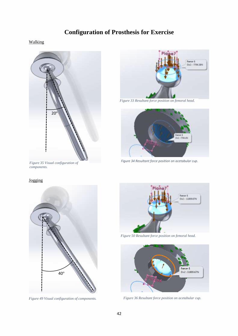
Figure 35 Visual configuration of
components.
Figure 49 Visual configuration of components.
Configuration of Prosthesis for Exercise
Walking
Jogging
20°
Figure 33 Resultant force position on femoral head.
40°
Figure 50 Resultant force position on femoral head.
Figure 36 Resultant force position on acetabular cup.
Figure 34 Resultant force position on acetabular cup.
43
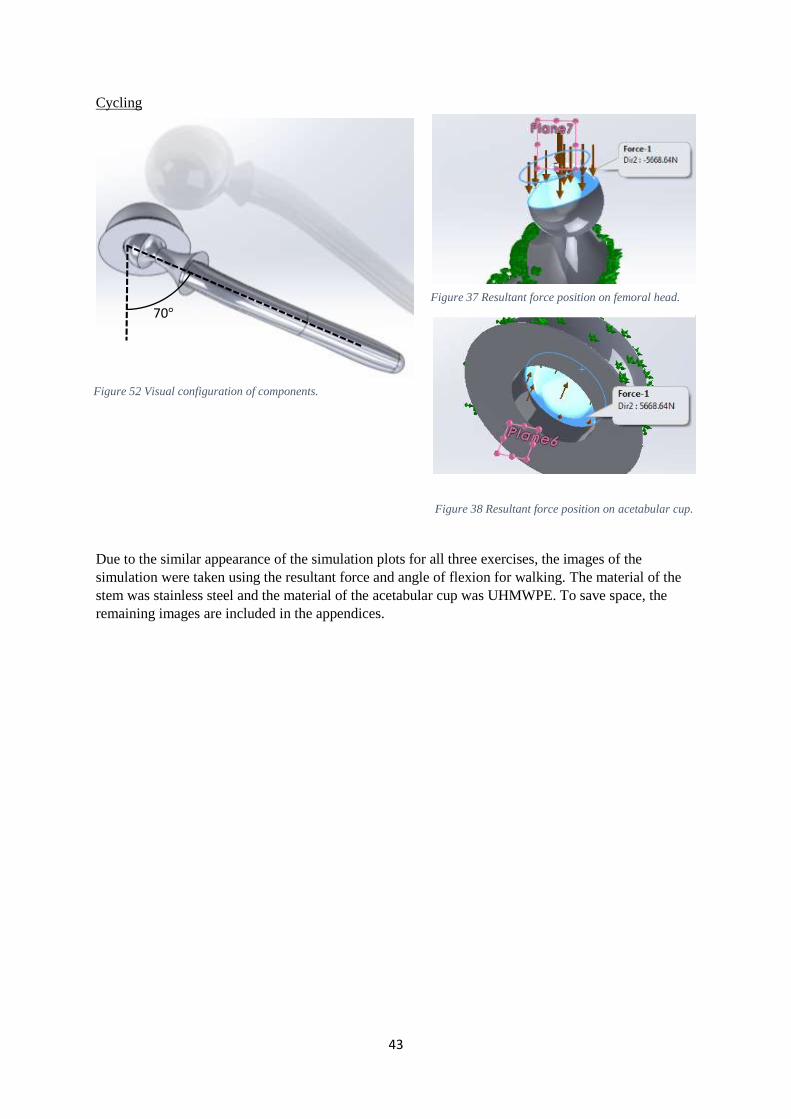
Figure 52 Visual configuration of components.
Cycling
Due to the similar appearance of the simulation plots for all three exercises, the images of the
simulation were taken using the resultant force and angle of flexion for walking. The material of the
stem was stainless steel and the material of the acetabular cup was UHMWPE. To save space, the
remaining images are included in the appendices.
70° Figure 37 Resultant force position on femoral head.
Figure 38 Resultant force position on acetabular cup.
44
FEA Simulation Plots
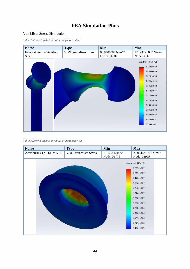
Von Mises Stress Distribution
Table 7 Stress distribution values of femoral stem.
Name Type Min Max
Femoral Stem – Stainless
Steel
VON: von Mises Stress 0.00408884 N/m^2
Node: 54448
1.15417e+009 N/m^2
Node: 4042
Table 8 Stress distribution values of acetabular cup.
Name Type Min Max
Acetabular Cup - UHMWPE VON: von Mises Stress 119588 N/m^2
Node: 53775
2.60344e+007 N/m^2
Node: 52905
45
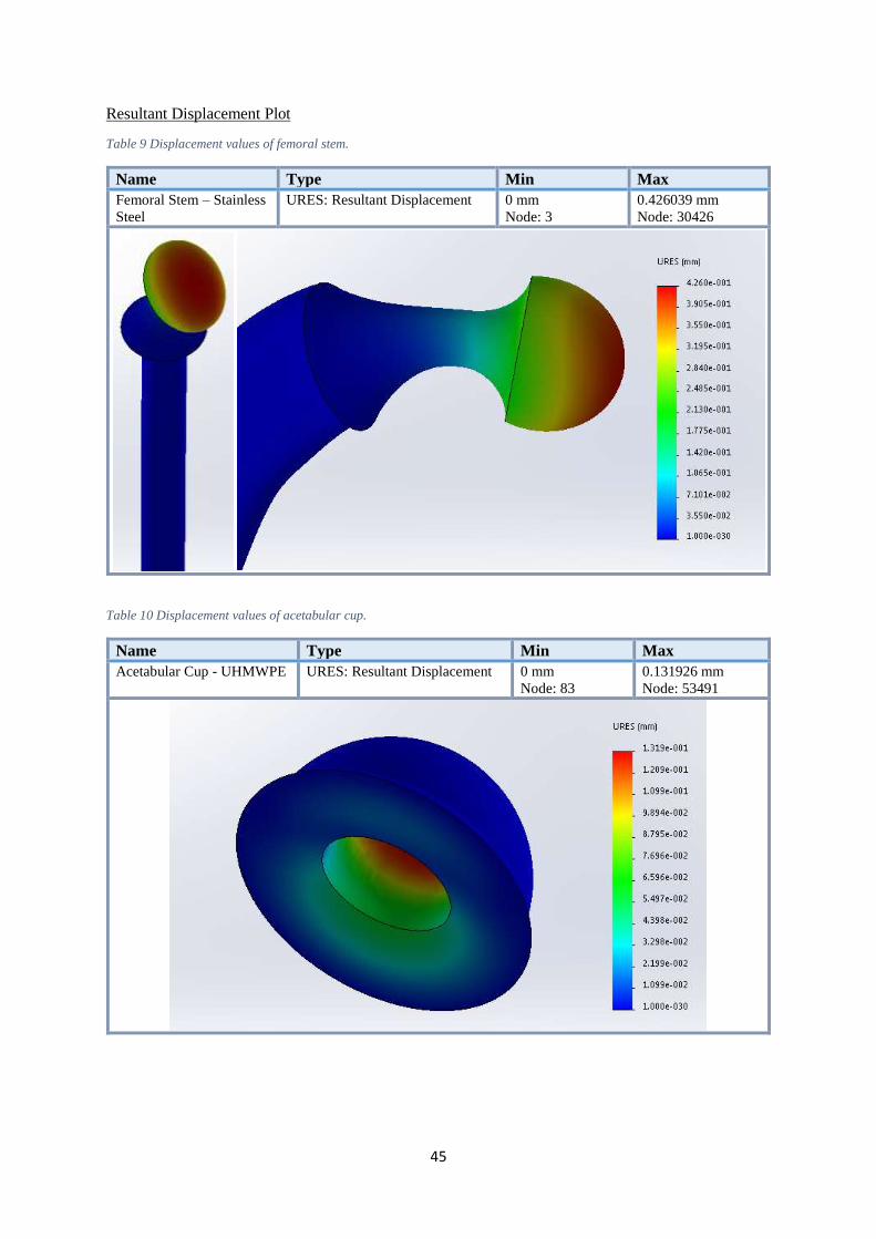
Resultant Displacement Plot
Table 9 Displacement values of femoral stem.
Name Type Min Max
Femoral Stem – Stainless
Steel
URES: Resultant Displacement 0 mm
Node: 3
0.426039 mm
Node: 30426
Table 10 Displacement values of acetabular cup.
Name Type Min Max
Acetabular Cup - UHMWPE URES: Resultant Displacement 0 mm
Node: 83
0.131926 mm
Node: 53491
46
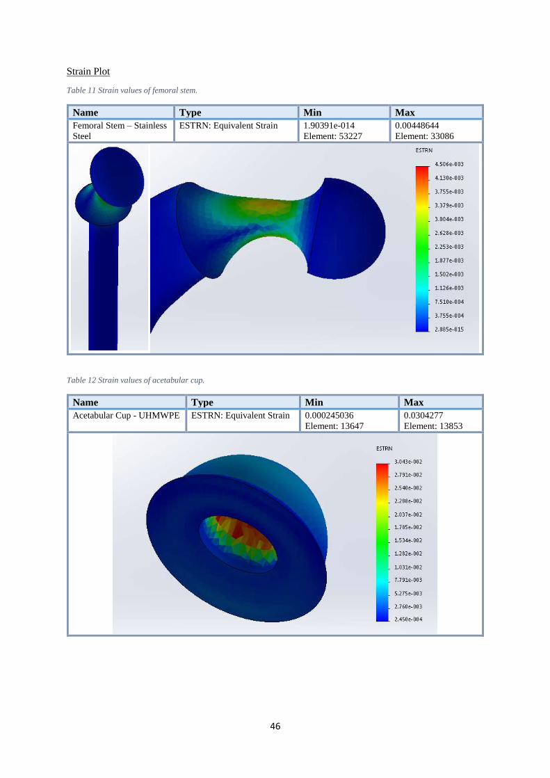
Strain Plot
Table 11 Strain values of femoral stem.
Name Type Min Max
Femoral Stem – Stainless
Steel
ESTRN: Equivalent Strain 1.90391e-014
Element: 53227
0.00448644
Element: 33086
Table 12 Strain values of acetabular cup.
Name Type Min Max
Acetabular Cup - UHMWPE ESTRN: Equivalent Strain 0.000245036
Element: 13647
0.0304277
Element: 13853
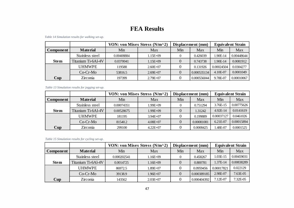
47
FEA Results
Table 14 Simulation results for walking set-up.
Table 13 Simulation results for jogging set-up.
Table 15 Simulation results for cycling set-up.
Component Material Min Max Min Max Min Max
Stainless steel 0.000202541 1.16E+09 0 0.458267 1.03E-15 0.00459031
Titanium Ti-6Al-4V 0.0014725 1.16E+09 0 0.800781 1.37E-14 0.00838289
UHMWPE 86972.5 1.89E+07 0 0.0959456 0.00017821 0.022129
Co-Cr-Mo 39138.9 1.96E+07 0 0.000389185 2.98E-07 7.63E-05
Zirconia 143562 2.03E+07 0 0.000404392 7.12E-07 7.32E-05
Stem
Cup
VON: von Mises Stress (N/m^2) Displacement (mm) Equivalent Strain
Component Material Min Max Min Max Min Max
Stainless steel 0.00074351 1.99E+09 0 0.751294 3.76E-15 0.00775626
Titanium Ti-6Al-4V 0.00528675 1.99E+09 0 1.31242 4.92E-14 0.0141619
UHMWPE 181195 3.94E+07 0 0.199889 0.00037127 0.0461026
Co-Cr-Mo 81540.2 4.08E+07 0 0.00081081 6.21E-07 0.00015894
Zirconia 299100 4.22E+07 0 0.0008425 1.48E-07 0.0001525
VON: von Mises Stress (N/m^2) Displacement (mm) Equivalent Strain
Stem
Cup
Component Material Min Max Min Max Min Max
Stainless steel 0.00408884 1.15E+09 0 0.426039 1.90E-14 0.00448644
Titanium Ti-6Al-4V 0.0370041 1.15E+09 0 0.743738 1.90E-14 0.0081912
UHMWPE 119588 2.60E+07 0 0.131926 0.00024504 0.0304277
Co-Cr-Mo 53816.5 2.69E+07 0 0.000535134 4.10E-07 0.0001049
Zirconia 197399 2.79E+07 0 0.000556044 9.78E-07 0.00010067
Equivalent Strain
Stem
Cup
VON: von Mises Stress (N/m^2) Displacement (mm)
48
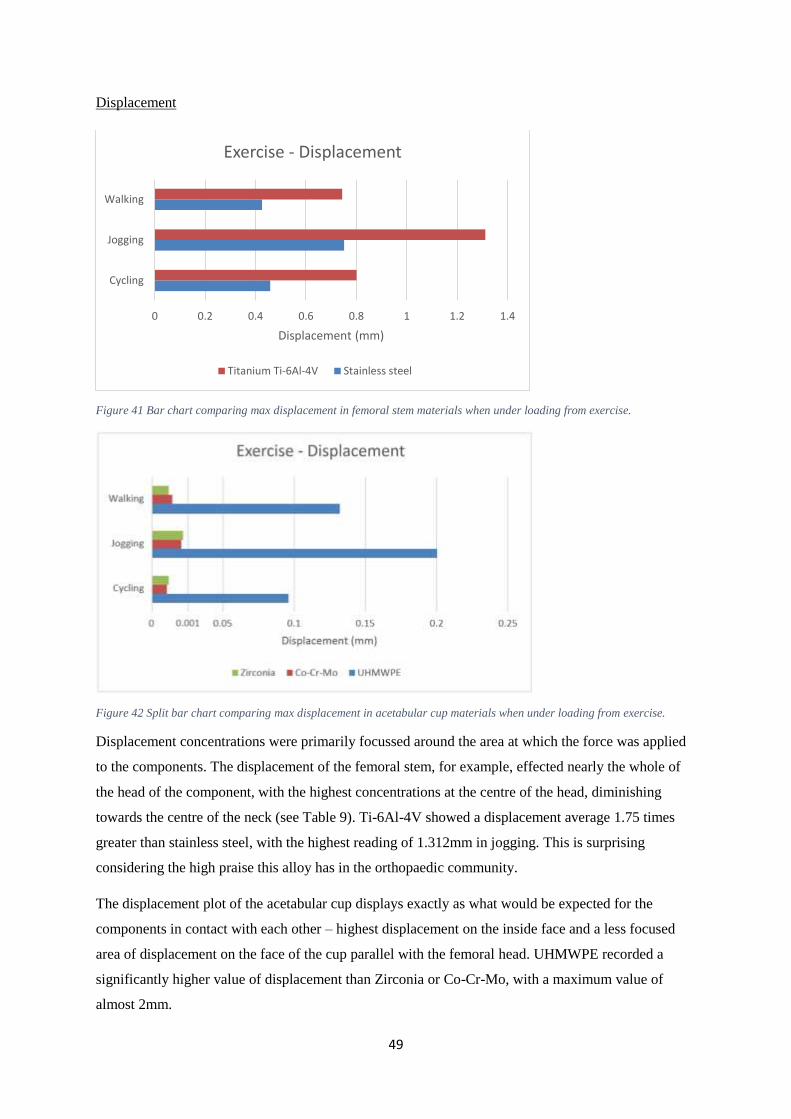
Interpretation of Results
Von Mises Stress
Figure 39 Bar chart comparing max von Mises stress in femoral stem materials when under loading from exercise.
The von Mises stress stayed practically constant for each exercise, especially in the femoral stem
simulations. This could be attributed to the fact stress is force over area, therefore because the area of
each component did not vary, the total von Mises stress is proportional to the force applied. This also
explains the characteristic increase in stress with higher loading.
One explanation for the highest stress in Zirconia and the lowest in UHMWPE is the different values
of Young’s Modulus for each material. Between these materials, the stress fluctuated by an average of
2.8MN𝑚−2, approximately 6.6%. Although these differences are not significant, they are still a factor
to take into account in addressing the material’s response to high loading.
0.00E+00 5.00E+08 1.00E+09 1.50E+09 2.00E+09 2.50E+09
Cycling
Jogging
Walking
von Mises Stress (N/m^2)
Exercise - Stress
Titanium Ti-6Al-4V Stainless steel
Figure 40 Bar chart comparing max von Mises stress in acetabulum cup materials when under loading from exercise.
0.00E+00 1.00E+07 2.00E+07 3.00E+07 4.00E+07 5.00E+07
Cycling
Jogging
Walking
von Mises Stress (N/m^2)
Exercise - Stress
Zirconia Co-Cr-Mo UHMWPE
49
Displacement
Figure 41 Bar chart comparing max displacement in femoral stem materials when under loading from exercise.
Figure 42 Split bar chart comparing max displacement in acetabular cup materials when under loading from exercise.
Displacement concentrations were primarily focussed around the area at which the force was applied
to the components. The displacement of the femoral stem, for example, effected nearly the whole of
the head of the component, with the highest concentrations at the centre of the head, diminishing
towards the centre of the neck (see Table 9). Ti-6Al-4V showed a displacement average 1.75 times
greater than stainless steel, with the highest reading of 1.312mm in jogging. This is surprising
considering the high praise this alloy has in the orthopaedic community.
The displacement plot of the acetabular cup displays exactly as what would be expected for the
components in contact with each other – highest displacement on the inside face and a less focused
area of displacement on the face of the cup parallel with the femoral head. UHMWPE recorded a
significantly higher value of displacement than Zirconia or Co-Cr-Mo, with a maximum value of
almost 2mm.
0 0.2 0.4 0.6 0.8 1 1.2 1.4
Cycling
Jogging
Walking
Displacement (mm)
Exercise - Displacement
Titanium Ti-6Al-4V Stainless steel
50
Strain
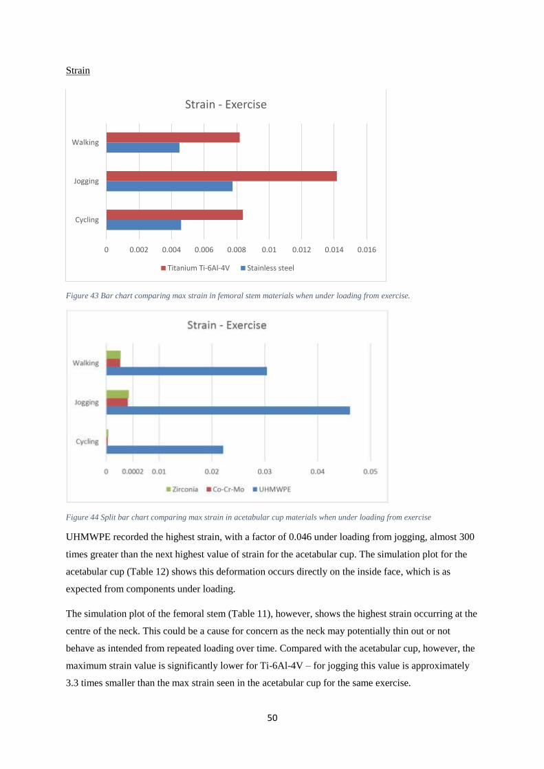
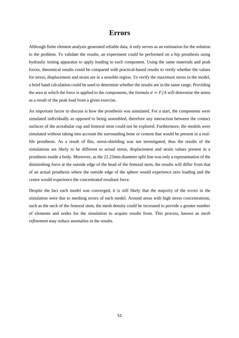
Figure 43 Bar chart comparing max strain in femoral stem materials when under loading from exercise.
Figure 44 Split bar chart comparing max strain in acetabular cup materials when under loading from exercise
UHMWPE recorded the highest strain, with a factor of 0.046 under loading from jogging, almost 300
times greater than the next highest value of strain for the acetabular cup. The simulation plot for the
acetabular cup (Table 12) shows this deformation occurs directly on the inside face, which is as
expected from components under loading.
The simulation plot of the femoral stem (Table 11), however, shows the highest strain occurring at the
centre of the neck. This could be a cause for concern as the neck may potentially thin out or not
behave as intended from repeated loading over time. Compared with the acetabular cup, however, the
maximum strain value is significantly lower for Ti-6Al-4V – for jogging this value is approximately
3.3 times smaller than the max strain seen in the acetabular cup for the same exercise.
0 0.002 0.004 0.006 0.008 0.01 0.012 0.014 0.016
Cycling
Jogging
Walking
Strain - Exercise
Titanium Ti-6Al-4V Stainless steel
51
Errors
Although finite element analysis generated reliable data, it only serves as an estimation for the solution
to the problem. To validate the results, an experiment could be performed on a hip prosthesis using
hydraulic testing apparatus to apply loading to each component. Using the same materials and peak
forces, theoretical results could be compared with practical-based results to verify whether the values
for stress, displacement and strain are in a sensible region. To verify the maximum stress in the model,
a brief hand calculation could be used to determine whether the results are in the same range. Providing
the area at which the force is applied to the components, the formula 𝜎 = 𝐹/𝐴 will determine the stress
as a result of the peak load from a given exercise.
An important factor to discuss is how the prosthesis was simulated. For a start, the components were
simulated individually as opposed to being assembled, therefore any interaction between the contact
surfaces of the acetabular cup and femoral stem could not be explored. Furthermore, the models were
simulated without taking into account the surrounding bone or cement that would be present in a real-
life prosthesis. As a result of this, stress-shielding was not investigated, thus the results of the
simulations are likely to be different to actual stress, displacement and strain values present in a
prosthesis inside a body. Moreover, as the 21.23mm diameter split line was only a representation of the
diminishing force at the outside edge of the head of the femoral stem, the results will differ from that
of an actual prosthesis where the outside edge of the sphere would experience zero loading and the
centre would experience the concentrated resultant force.
Despite the fact each model was converged, it is still likely that the majority of the errors in the
simulation were due to meshing errors of each model. Around areas with high stress concentrations,
such as the neck of the femoral stem, the mesh density could be increased to provide a greater number
of elements and nodes for the simulation to acquire results from. This process, known as mesh
refinement may reduce anomalies in the results.
52
Discussion
The results from the simulation of the femoral stem show that stainless steel is the best choice of
material for resisting displacement and strain when load is applied to the femoral head. However, when
the stem is fixed inside the femur, some displacement is not necessarily bad as it reduces the stress
shielding against the bone surfaces. Therefore it could be said that stainless steel is, in fact, not suitable
to be used as the material of a femoral stem. On the contrary, for patients with a very active lifestyle,
particular those who partake in regular high impact exercise, stress shielding of the femur may be of
less concern than constant displacement of the femoral stem as is the case with titanium alloy Ti-6Al-
4V. Although this alloy has a far greater biocompatibility than stainless steel, if the femoral stem is
displaced and under strain for repeated exercise, the prosthesis is far more likely to fail. Furthermore,
if a porous titanium alloy such as Ti-6Al-4V 40% porosity is used, the repeated high displacement and
deformation of the component may even loosen the bond of osseointegration of the surface of the femur.
Nonetheless, for a low loading exercise, Ti-6Al-4V is perfectly suitable to be used as femoral stem,
especially considering there is no danger of the patient suffering an allergic reaction to the material
unlike with nickel used in stainless steel.
The results from the simulation of the acetabular cup make it very clear that ultra-high molecular weight
polyethylene is unsuitable for active patients. Although the material is cost effective and reliable, the
massive displacements of the inside surface in contact with the femoral head are a huge cause for
concern. It is simply impractical for younger patients to use an acetabular cup that poses the risk of
dislocation or subluxation due to the high deformation when under loading. Additionally, due to
UHMWPE having the highest material wear-rate out of the materials studied, under exercise with high
cyclic loading such as cycling, the acetabular cup will wear out extremely fast. Combined with high
deformation, this repetitive motion could cause premature loosening of prosthesis which for younger
patients is extremely dangerous as the need for revision surgery will be very high.
Realistically, Zirconia and Co-Cr-Mo are the only suitable acetabular cup materials regardless of what
loading they are subjected to. However, Zirconia would be better suited to a patient with an interest in
cycling as the material is very much suited to high repetition-low load exercises. Due the extremely
hard nature of the material, Zirconia could resist the many thousands of revolutions of the leg during a
short space of time, and as the resultant force on the hip is relatively low during cycling, it poses no
danger of potentially cracking or fracturing the ceramic from a high impact load. Likewise, Co-Cr-Mo
is much more suited to lower repetition-high load exercise. Although there is a danger of metallosis
occurring from debris of the components rubbing against each other, it could be argued that a far greater
problem would be an acetabular cup cracking, as could be the case with Zirconia used for such exercises.
53
One important factor to discuss is the inability to simulate the femoral head as a different material
such as ceramic or an alternative metal. As explained, technical difficulties were encountered within
SolidWorks when trying to run the simulation on an assembly of mated components. As a result of
this, the femoral head and shaft were kept as one component and the acetabulum as another. It would
have been futile to simulate the femoral head as a separate component to the stem as result plots in the
simulation would not show how stress, displacement and strain are distributed from the head across
the neck of the stem.
Conclusion
Overall the use of finite element analysis was successful as the simulations were able to provide a
value of maximum stress, displacement, and strain of the prosthesis components when under loading
from exercise. The results from the simulations are sufficient to fill the gap in current research made
into this topic, and offer a strong starting point for anyone wishing to further explore the effects of
exercise on hip prostheses. To summarise, the optimum material combination for high impact loading
is a stainless steel femoral stem and a Co-Cr-Mo acetabular cup, and for low impact but high
frequency loading, a titanium Ti-6Al-4V femoral stem and Zirconia acetabular cup.
Using this information, orthopaedic surgeons could decide which materials of components to use in
the prostheses for active patients.
54
Future Work
One important factor to explore is how exercise effects the material wear-rate of the prosthesis
components. In this project, the hip was analysed in a stationary position with the peak load of the
exercise occurring at the maximum angle of flexion of the leg, but did not include cyclic loading from
the exercise that the hip would experience in real-life. The FEA package ANSYS offers a way to
perform this simulation through a process known as time dependent loading. By calculating the load of
the hip joint through each angle of flexion for the exercise, it would be possible to calculate the wear-
rate of the components providing the coefficient of friction is known for each contact surface.
Alternatively, the assembled prosthesis could be analysed using a cyclic loading machine, which are
currently used to compare material wear-rates between of the components, but are costly and require a
lot of time to generate results.
Another aspect to consider is the effect of fatigue on the components. If the maximum and minimum
load on the hip joint experienced is known, a fatigue analysis simulations could be performed on the
prosthesis between this range of force. The results of these simulations could then be plotted in a series
of graphs to compare factors such as the time taken for the component to fail. Using this information,
surgeons could confidentially select materials of components based on how active the patient is, e.g
using a Zirconia acetabular cup for patient a who cycles frequently.
In order to keep the finite element analysis results relevant, simulations should be repeated with ‘future’
materials of components. With the increasing advances in bioengineering technology, orthopaedic
companies use materials tailored to suite every requirement of the component in order to stay
competitive with other products. I made contact was made with Mr. Ingham, an employee of Zimmer
Orthopaedics, to discuss future materials in hip prosthesis components. Mr. Ingham emailed me
brochures of their newest components using state of the art materials. Trabecular Metal™ boasts up to
80% porosity and has an extremely low coefficient of friction making it one of their most innovative
products. [21] Simulating materials such as these would be a good way of comparing how future
materials compare with conventional materials of components and could provide surgeons with the
information to decide on whether these implants are effective.
The effects of exercise on hip prostheses could also be explored using a different style prosthesis and a
different method of exercise. The Mckee-Farrar prosthesis, for example, would produce different
simulation results to the Charnley prosthesis due to the increase in femoral head size, and an exercise
such as weightlifting would exert a far larger peak load on the hip. A study on the relationship between
types of prostheses and how they distribute loading could be made to compare these variables.
55
Lastly, the hip prosthesis could be improved either by changing the shape or size of each component. It
is already standard knowledge that a larger diameter femoral head will increase wear in between the
acetabular cup, but how would this effect displacement or deformation in areas with high force
concentration. By investigating the factor of safety (FOS) of the design for each model, either from trial
and error or biomechanical assessment, the prosthesis components could be modified to increase the
minimum value which would prove it is X times stronger than it needs to be. A study could then be
made into the minimum FOS value of each prosthesis required to safely subject the hip to loading from
exercise.
56
References
[1] National Joint Registry. 2010. Joint replacement statistics. [ONLINE] Available at:
http://www.njrcentre.org.uk/njrcentre/Patients/Jointreplacementstatistics/tabid/99/Default.aspx. [Accessed 24
March 15].
[2] AAHKS. 2013. Total Hip Replacement. [ONLINE] Available at: http://www.aahks.org/care-for-hips-and-
knees/do-i-need-a-joint-replacement/total-hip-replacement/. [Accessed 24 March 15].
[3] Arthritis Today. 2010. Best Hip Replacement Options for Younger Patients. [ONLINE] Available at:
http://www.arthritistoday.org/news/hip-replacements-younger-patients046.php. [Accessed 24 March 15].
[4] NHS. 2014. Hip replacement - Recovery. [ONLINE] Available at: http://www.nhs.uk/conditions/Hip-
replacement/Pages/Recovery.aspx. [Accessed 24 March 15].
[5] Love to Know / MKDanielsson. 2014. Risks of Not Exercising. [ONLINE] Available at:
http://exercise.lovetoknow.com/Risks_of_Not_Exercising. [Accessed 24 March 15].
[6] Teach Me Anatomy. 2014. The Hip Joint. [ONLINE] Available at: http://teachmeanatomy.info/lower-
limb/joints/the-hip-joint/.
[7] Inner Body. 2014. Hip Joint. [ONLINE] Available at: http://www.innerbody.com/image/skel15.html.
[Accessed 09 March 15].
[8] OrthoInfo. 2014. Osetoarthritis of the Hip. [ONLINE] Available at:
http://orthoinfo.aaos.org/topic.cfm?topic=a00213. [Accessed 10 March 15].
[9] NHS. 2014. Hip Fracture. [ONLINE] Available at: http://www.nhs.uk/conditions/hip-
fracture/Pages/introduction.aspx. [Accessed 10 March 15].
[10] NHS. 2014. Hip Pain In Adults. [ONLINE] Available at: http://www.nhs.uk/conditions/hip-pain-
adults/Pages/Introduction.aspx. [Accessed 10 March 15].
[11] Arthritis Research UK. 2014. What treatments are there for hip pain?. [ONLINE] Available at:
http://www.arthritisresearchuk.org/arthritis-information/conditions/hip-pain/treatments.aspx. [Accessed 10
March 15].
[12] News-Medical. 2014. Hip Replacement History. [ONLINE] Available at: http://www.news-
medical.net/health/Hip-Replacement-History.aspx. [Accessed 11 March 15].
[13] William Waugh (1990). John Charnley - The Man and The Hip. London: Springer. 157.
[14] Colorado Hip Resurfacing. 2007. History of Hip Resurfacing. [ONLINE] Available at:
http://www.coloradohipresurfacing.com/English/BHR_History/history01.html. [Accessed 11 March 15].
[15] L A Reynolds and E M Tansey. (2006). EARLY DEVELOPMENT OF TOTAL HIP REPLACEMENT.
Volume 29, 19
[16] L A Reynolds and E M Tansey. (2006). EARLY DEVELOPMENT OF TOTAL HIP REPLACEMENT.
Volume 29, 16-
[17] BBC. 2015. A metal artificial hip replacement. [ONLINE] Available at:
http://www.bbc.co.uk/ahistoryoftheworld/objects/XvHW8eEwQ7y14rYyZFNU9A. [Accessed 18 March 15].
[18] Bone Smart. 2014. Types of Total Hip Implants and Fixation. [ONLINE] Available at:
http://bonesmart.org/hip/types-of-total-hip-implants/. [Accessed 02 March 15].
[19] Arthritis Research UK. 2014. The challenge of revision hip replacement surgery. [ONLINE] Available at:
http://www.arthritisresearchuk.org/arthritis-information/arthritis-today-magazine/159-winter-2013/the-
challenge-of-revision-hip-replacement-surgery.aspx. [Accessed 02 March 15].
57
[20] Royal Free NHS London. 2014. Prosthetic Implants. [ONLINE] Available at:
https://www.royalfree.nhs.uk/services/services-a-z/plastic-surgery/prosthetic-limbs-and-body-parts/prosthetic-
implants/. [Accessed 03 March 15].
[21] Zimmer Orthopaedics. 2015. Trabecular Metal™ Technology. [ONLINE] Available at:
http://www.zimmer.com/medical-professionals/our-science/common/trabecular-metal-technology.html.
[Accessed 18 March 15].
[22] Colorado Hip Resurfacing. 2015. History of Hip Resurfacing. [ONLINE] Available at:
http://www.coloradohipresurfacing.com/English/BHR_History/history09.html. [Accessed 18 March 15].
[23] Carole St.-Jean Natalie Fish. (2011). Osseointegration: Examining the Pros and Cons. inMotion. 21 (5),
46-47.
[24] Bone Joint J 2013;95-B:874–6
[25] Health Pages. 2015. Hip Joint Replacement Surgery. [ONLINE] Available at:
http://www.healthpages.org/surgical-care/hip-joint-replacement-surgery/. [Accessed 18 March 15].
[26] ROBERT A. MARSTON, A G. Cobb, G Bentley. STANMORE COMPARED WITH CHARNLEY TOTAL
HIP REPLACEMENT. Bone and Joint Surgery. 1.
[27] Methodist Orthopaedics. 2002. Artificial Joint Replacement of the Hip. [ONLINE] Available at:
http://www.methodistorthopedics.com/artificial-joint-replacement-of-the-hip. [Accessed 18 March 15].
[28] CHARNLEY MODULAR, Charnley in the 21st Century. DePuy Orthopaedics.
[29] CHI St. Luke's Health. 2015. HIP/JOINT/KNEE REPLACEMENT SERVICES. [ONLINE] Available at:
http://www.stlukeshouston.com/OurServices/Orthopedic_Services/Hip_Joint_St_Lukes_Houston.cfm.
[Accessed 18 March 15].
[30] DoITPoMS. 2014. Materials selection of femoral stem component. [ONLINE] Available at:
http://www.doitpoms.ac.uk/tlplib/bones/stem.php. [Accessed 18 March 15].
[31] emedicinehealth. 2015. What Is Bone Loss. [ONLINE] Available at:
http://www.emedicinehealth.com/what_is_bone_loss/page3_em.htm. [Accessed 18 March 15].
[32] ASBMR. 2015. Bone Structure and Function. [ONLINE] Available at:
https://depts.washington.edu/bonebio/ASBMRed/structure.html. [Accessed 18 March 15].
[33] CG. 2015. Foam Visualization and Investigation Tool. [ONLINE] Available at:
http://www.cg.tuwien.ac.at/research/vis/Miscellaneous/alufoam/. [Accessed 18 March 15].
[34] DoITPoMS. 2015. Materials selection of femoral head and acetabular cup components. [ONLINE]
Available at: http://www.doitpoms.ac.uk/tlplib/bones/head.php. [Accessed 18 March 15].
[35] SR Knight, R Aujla, SP Biswas. (2011). Total Hip Arthroplasty - over 100 years of operative history.
Orthopaedic Review. 3 (2), 1.
[36] Bone Smart. 2015. Hip Replacement Implant Materials. [ONLINE] Available at:
http://bonesmart.org/hip/hip-replacement-implant-materials/. [Accessed 18 March 15].
[37] Drug Watch. 2015. Metal Poisoning & Metallosis. [ONLINE] Available at:
http://www.drugwatch.com/hip-replacement/metallosis/. [Accessed 18 March 15].
[38] FDA. 2014. Recalls. [ONLINE] Available at:
http://www.fda.gov/MedicalDevices/ProductsandMedicalProcedures/ImplantsandProsthetics/MetalonMetalHipI
mplants/ucm241770.htm. [Accessed 18 March 15].
[39] Lawyers and Settlements. 2014. DePuy Orthopaedics Metal Hip Replacement. [ONLINE] Available at:
http://www.lawyersandsettlements.com/lawsuit/depuy-hip-replacement-recall.html#.VRqnePlMmWY.
[Accessed 18 March 15].
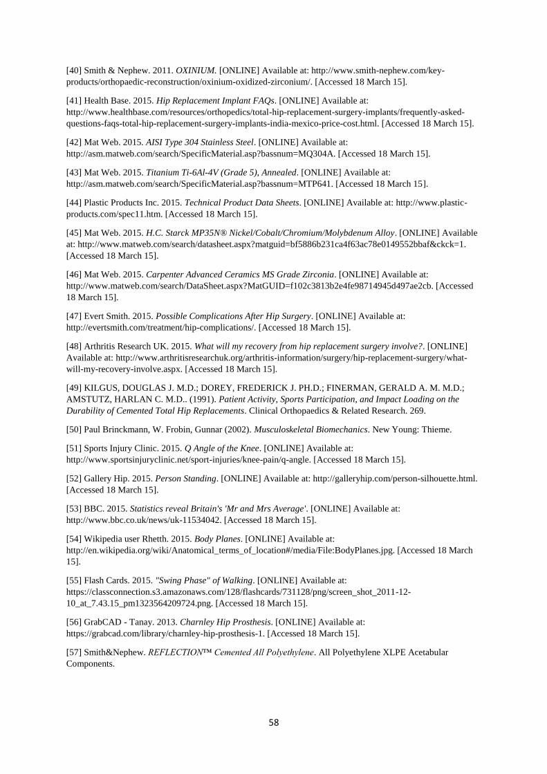
58
[40] Smith & Nephew. 2011. OXINIUM. [ONLINE] Available at: http://www.smith-nephew.com/key-
products/orthopaedic-reconstruction/oxinium-oxidized-zirconium/. [Accessed 18 March 15].
[41] Health Base. 2015. Hip Replacement Implant FAQs. [ONLINE] Available at:
http://www.healthbase.com/resources/orthopedics/total-hip-replacement-surgery-implants/frequently-asked-
questions-faqs-total-hip-replacement-surgery-implants-india-mexico-price-cost.html. [Accessed 18 March 15].
[42] Mat Web. 2015. AISI Type 304 Stainless Steel. [ONLINE] Available at:
http://asm.matweb.com/search/SpecificMaterial.asp?bassnum=MQ304A. [Accessed 18 March 15].
[43] Mat Web. 2015. Titanium Ti-6Al-4V (Grade 5), Annealed. [ONLINE] Available at:
http://asm.matweb.com/search/SpecificMaterial.asp?bassnum=MTP641. [Accessed 18 March 15].
[44] Plastic Products Inc. 2015. Technical Product Data Sheets. [ONLINE] Available at: http://www.plastic-
products.com/spec11.htm. [Accessed 18 March 15].
[45] Mat Web. 2015. H.C. Starck MP35N® Nickel/Cobalt/Chromium/Molybdenum Alloy. [ONLINE] Available
at: http://www.matweb.com/search/datasheet.aspx?matguid=bf5886b231ca4f63ac78e0149552bbaf&ckck=1.
[Accessed 18 March 15].
[46] Mat Web. 2015. Carpenter Advanced Ceramics MS Grade Zirconia. [ONLINE] Available at:
http://www.matweb.com/search/DataSheet.aspx?MatGUID=f102c3813b2e4fe98714945d497ae2cb. [Accessed
18 March 15].
[47] Evert Smith. 2015. Possible Complications After Hip Surgery. [ONLINE] Available at:
http://evertsmith.com/treatment/hip-complications/. [Accessed 18 March 15].
[48] Arthritis Research UK. 2015. What will my recovery from hip replacement surgery involve?. [ONLINE]
Available at: http://www.arthritisresearchuk.org/arthritis-information/surgery/hip-replacement-surgery/what-
will-my-recovery-involve.aspx. [Accessed 18 March 15].
[49] KILGUS, DOUGLAS J. M.D.; DOREY, FREDERICK J. PH.D.; FINERMAN, GERALD A. M. M.D.;
AMSTUTZ, HARLAN C. M.D.. (1991). Patient Activity, Sports Participation, and Impact Loading on the
Durability of Cemented Total Hip Replacements. Clinical Orthopaedics & Related Research. 269.
[50] Paul Brinckmann, W. Frobin, Gunnar (2002). Musculoskeletal Biomechanics. New Young: Thieme.
[51] Sports Injury Clinic. 2015. Q Angle of the Knee. [ONLINE] Available at:
http://www.sportsinjuryclinic.net/sport-injuries/knee-pain/q-angle. [Accessed 18 March 15].
[52] Gallery Hip. 2015. Person Standing. [ONLINE] Available at: http://galleryhip.com/person-silhouette.html.
[Accessed 18 March 15].
[53] BBC. 2015. Statistics reveal Britain's 'Mr and Mrs Average'. [ONLINE] Available at:
http://www.bbc.co.uk/news/uk-11534042. [Accessed 18 March 15].
[54] Wikipedia user Rhetth. 2015. Body Planes. [ONLINE] Available at:
http://en.wikipedia.org/wiki/Anatomical_terms_of_location#/media/File:BodyPlanes.jpg. [Accessed 18 March
15].
[55] Flash Cards. 2015. "Swing Phase" of Walking. [ONLINE] Available at:
https://classconnection.s3.amazonaws.com/128/flashcards/731128/png/screen_shot_2011-12-
10_at_7.43.15_pm1323564209724.png. [Accessed 18 March 15].
[56] GrabCAD - Tanay. 2013. Charnley Hip Prosthesis. [ONLINE] Available at:
https://grabcad.com/library/charnley-hip-prosthesis-1. [Accessed 18 March 15].
[57] Smith&Nephew. REFLECTION™ Cemented All Polyethylene. All Polyethylene XLPE Acetabular
Components.
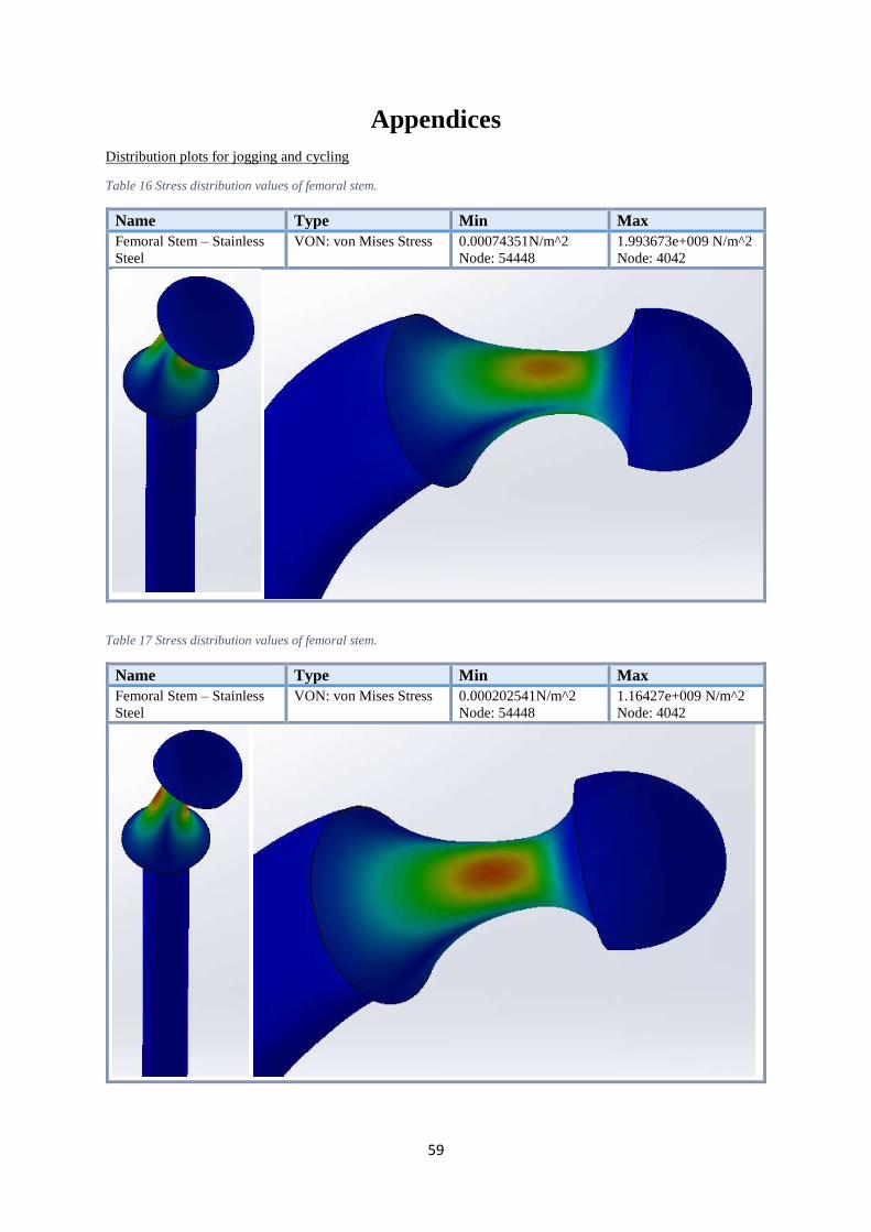
59
Appendices
Distribution plots for jogging and cycling
Table 16 Stress distribution values of femoral stem.
Name Type Min Max
Femoral Stem – Stainless
Steel
VON: von Mises Stress 0.00074351N/m^2
Node: 54448
1.993673e+009 N/m^2
Node: 4042
Table 17 Stress distribution values of femoral stem.
Name Type Min Max
Femoral Stem – Stainless
Steel
VON: von Mises Stress 0.000202541N/m^2
Node: 54448
1.16427e+009 N/m^2
Node: 4042

60
Plan
of A
ctivities: Gan
tt chart