Embed Size (px)
Citation preview
Page 1
FINAL VERSION
Feasibility study of an internally cooled bipolar applicator for RF
coagulation of hepatic tissue: Experimental and computational study
Ana González-Suárez1, Macarena Trujillo2, Fernando Burdío3,
Anna Andaluz4, Enrique Berjano1
1 Biomedical Synergy, Electronic Engineering Department, Universitat Politècnica de
València, Valencia, Spain
2 Instituto Universitario de Matemática Pura y Aplicada, Universitat Politècnica de
València, Valencia, Spain
3 General Surgery Department, Hospital del Mar, Barcelona, Spain.
4 Departament de Medicina i Cirurgia Animals, Facultat de Veterinària, Universitat
Autònoma de Barcelona, Barcelona, Spain
*To whom all correspondence should be addressed:
Dr. Enrique Berjano
Electronic Engineering Department (7F)
Universitat Politècnica de València, Spain
Camino de Vera, 46022 Valencia, Spain
Email: [email protected]
Running Head: Cooled bipolar applicator for hepatic RF coagulation
Page 2
Purpose: To study the capacity of an internally cooled radiofrequency (RF) bipolar
applicator to create sufficiently deep thermal lesions in hepatic tissue.
Materials and methods: Three complementary methodologies were employed to check
the electrical and thermal behavior of the applicator under test. The experimental studies
were based on excised bovine (ex vivo study) and porcine liver (in vivo study) and the
numerical models were solved by means of the Finite Element Method (FEM).
Results: Experimental and numerical results showed good agreement in terms of
impedance progress and lesion depth (4 and 4.5 mm respectively for ex vivo conditions,
and ≈7 and 9 mm respectively for in vivo conditions), although the lesion widths were
overestimated by the computer simulations. This could have been due to the method
used to assess the thermal lesions; the experimental lesions were assessed by the white
coagulation zone whereas the tissue damage function was used to assess the numerical
lesions.
Conclusions: The experimental results suggest that this applicator could create in vivo
lesions to a depth of around 7 mm. It was also observed that the thermal lesion is mainly
confined to the area between both electrodes, which would allow lesion width to be
controlled by selecting a specific applicator design. The comparison between the
experimental and numerical results suggests that the numerical model could be usefully
applied in further studies of the performance of this device.
Keywords: bipolar electrode, experimental model, finite element method, hepatic
resection, internally cooled electrode, radiofrequency ablation, numerical modeling.
Page 3
1. Introduction
Radiofrequency (RF) energy devices are widely used to thermally coagulate hepatic
tissue e.g. in the destruction of surface tumors [1,2] or minimizing blood loss during
hepatic resection by creating thermal coagulative necrosis along the transection plane
[3]. In both cases the goal is to achieve sufficiently deep thermal lesions. In the former
case the lesion should be deep enough to completely destroy the tumor, while in the
latter the objective is to seal the small vessels in the transection zone [4].
RF energy is applied to the tissue mostly by a monopolar arrangement between an
active electrode and a large conductive patch (dispersive electrode) in contact with the
patient’s skin. The TissueLink dissecting sealer (Salient Surgical Technologies,
Portsmouth, NH, USA) is one of the most widely used electro-surgical devices in
hepatic coagulation. Briefly, it is a monopolar electrode cooled by flushing saline
through openings in the electrode. This cooling method was previously proposed for RF
cardiac ablation in order to obtain deeper lesions and prevent both excessive heating at
the electrode-tissue interface and thrombus formation on the electrode [5-7]. In hepatic
RF coagulation this cooling method (also known as saline-linked) was used to prevent
surface charring and keep tissue surface temperature below 100ºC [1]. However, this
does not prevent the temperatures in the subsurface from rising above 100ºC, which can
lead to steam formation and expansion and even to disruption of the surface. The steam
may be audible as “steam pops”. In fact, undesirable effects such as steam pops,
impedance rise and charring of the tissue surface (and in some cases disruption) have
been observed in RF heating of cardiac and hepatic tissue [1,5,6] with both open and
closed irrigation [5,6]. The use of closed-irrigation (or internally cooled) RF electrodes
has been proposed not only for RF cardiac ablation [8] but also for RF-assisted resection
of liver, kidney and pancreas [9-11] to minimize blood loss during resection.
Page 4
Saline-linked technology has recently been implemented in a bipolar arrangement in
the Aquamantys System (Salient Surgical Technologies, Portsmouth, NH, USA) [12].
In general, bipolar electrodes are composed of two identical electrodes between which
RF current flows. This arrangement requires less power than the monopolar
configuration to achieve the same coagulating effect and has the additional advantage of
not needing a dispersive electrode, thus avoiding the risk of skin burns by poor contact
between the skin and the dispersive electrode. But most importantly, the use of bipolar
electrodes prevents RF currents flowing through adjacent tissue, thus minimizing the
risk of injury to other organs. This is especially important when surgery is performed by
the laparoscopic approach in conditions of reduced visibility [13].
Devices based on saline-drip, such as open-irrigation RF electrodes, have certain
disadvantages when compared to closed-irrigation electrodes: (1) the risk of burning
contiguous organs by hot saline, and (2) the saline flow rate is critical for producing the
desired haemostatic effect without excessive charring [14]. An internally cooled bipolar
RF applicator would therefore combine the above-mentioned advantages of the bipolar
configuration and would not have the drawbacks associated with open-irrigation RF
electrodes. Although some designs have been proposed for internally cooled bipolar RF
applicators, such as the Isolator (Atricure, Cincinnati, OH USA), designed to create
thermal lesions in cardiac tissue to cure atrial fibrillation [15], these electrodes had not
previously been considered to coagulate hepatic tissue, in particular to create thermal
lesions sufficiently deep for surface RF ablation or as sealing devices during surgical
resection. We therefore conducted a feasibility study of a closed-irrigation bipolar RF
applicator. The study was based on three complementary methodologies: ex vivo, in
vivo and numerical models. Due to their low cost, the ex vivo and numerical models
were used in the first step to check the electrical and thermal performance of the

Page 5
applicator under test. When its ability to create deep lesions had been assessed we then
conducted a pilot experimental in vivo test to check the results in a pre-clinical scenario.
Finally, additional computer simulations that modeled the in vivo scenario were
conducted to study the effect of the applied voltage and duration on the lesion depth and
to determine the potential of the cooled bipolar applicator to coagulate hepatic tissue.
These simulations were extended to the case of a smaller applicator especially designed
for laparoscopic use.
2. Materials and Methods
2.1 Description of the device
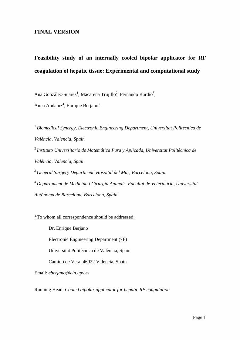
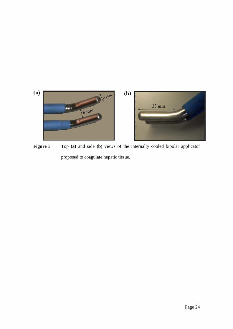
Fig. 1 shows the proposed device (D1), which consists of two identical electrodes 5
mm in diameter and 25 mm long, separated by a distance of 6 mm. We chose long
rather than pointed electrodes (as in the Aquamantys System) since we needed an
applicator able to create thermal coagulative necrosis along the transection plane, as
achieved by systems based on multiple-electrode arrays [16]. Internal cooling was set at
a volumetric flow rate of 100 mL/min and a coolant temperature of 5ºC. The electrodes
were connected to a CC-1 Cosman Coagulation System RF generator (Radionics,
Burlington, MA, USA), which delivers a non modulated sinusoidal waveform up to 100
V (rms) to a 100 Ω load at a maximum current of 1 A.
2.2 Ex vivo experimental setup
Six lesions were performed on the surface of excised bovine liver (4.5 kg weight,
17ºC initial temperature). The collagenous capsule (Glisson’s Capsule) covering the
external surface of the liver was removed prior to the RF application. Room temperature
was 22ºC. Internal cooling was conducted by means of a Model 323 peristaltic pump

Page 6
(Watson Marlow, Wilmington, MA, USA). We analyzed impedance progress during RF
heating and the geometry of the lesions created in the tissue after each heat application.
Impedance was sampled at 30 Hz and processed by means of Agilent VEE software
(Agilent Technologies, Santa Clara, CA, USA). Each lesion was sliced transversally in
order to characterize its geometry (see Fig. 4a). The thermal lesion geometry was
assessed by the white coagulation zone and its depth (D) and maximum width (W) were
quantified (see Fig. 4b). Both parameters were expressed as the mean ± standard
deviation. A Mann-Whitney Test was used to analyze the differences between groups.
Data collection and analysis of impedance progress were performed with Matlab® (The
MathWorks, Natick, MA, USA) and SPSS 17.0 (Chicago, IL, USA), respectively.
2.3 In vivo experimental setup
An in vivo pilot study was performed on a Landrace pig (58 kg) obtained from the
farm of the Universitat Autònoma de Barcelona (Barcelona, Spain) with the
authorization of the Ethical Commission of Animal and Human Experimentation
(Spanish Government) and under the control of the Ethical Commission of the
Universitat Autònoma de Barcelona (Authorization Number CEAAH 1256). The
anesthesia was supervised by a fully trained veterinary staff member. A combination of
azaperone and ketamine (4 mg/kg IM and 10 mg/kg IM) was used for initial sedation.
Once sedated, intravenous access was obtained by placing a 20G catheter in a marginal
ear vein and morphine (0.2 mg/kg IM) and meloxicam 0.2 mg/kg IV) were given as
analgesic therapy. Anesthetic induction was performed with propofol (4 mg/kg IV) and
maintained with isofluorane (vaporizer setting 2%) and 100% oxygen through a semi-
closed circular system (25 mL/kg/min oxygen). Lactated Ringer’s solution (10
mL/kg/hour) was administered through the same catheter throughout surgery.
Page 7
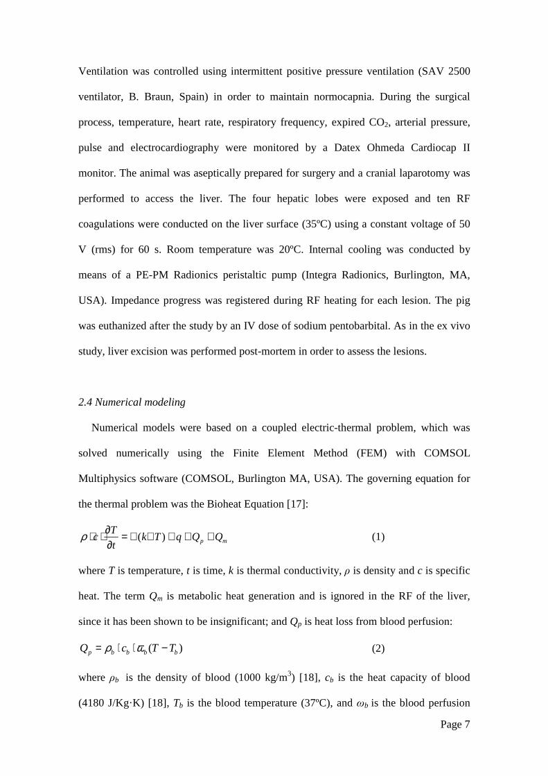
Ventilation was controlled using intermittent positive pressure ventilation (SAV 2500
ventilator, B. Braun, Spain) in order to maintain normocapnia. During the surgical
process, temperature, heart rate, respiratory frequency, expired CO2, arterial pressure,
pulse and electrocardiography were monitored by a Datex Ohmeda Cardiocap II
monitor. The animal was aseptically prepared for surgery and a cranial laparotomy was
performed to access the liver. The four hepatic lobes were exposed and ten RF
coagulations were conducted on the liver surface (35ºC) using a constant voltage of 50
V (rms) for 60 s. Room temperature was 20ºC. Internal cooling was conducted by
means of a PE-PM Radionics peristaltic pump (Integra Radionics, Burlington, MA,
USA). Impedance progress was registered during RF heating for each lesion. The pig
was euthanized after the study by an IV dose of sodium pentobarbital. As in the ex vivo
study, liver excision was performed post-mortem in order to assess the lesions.
2.4 Numerical modeling
Numerical models were based on a coupled electric-thermal problem, which was
solved numerically using the Finite Element Method (FEM) with COMSOL
Multiphysics software (COMSOL, Burlington MA, USA). The governing equation for
the thermal problem was the Bioheat Equation [17]:
mp QQqTkt
Tc +++∇∇=
∂∂⋅⋅ )(ρ
(1)
where T is temperature, t is time, k is thermal conductivity, ρ is density and c is specific
heat. The term Qm is metabolic heat generation and is ignored in the RF of the liver,
since it has been shown to be insignificant; and Qp is heat loss from blood perfusion:
)( bbbbp TTcQ −⋅⋅= ωρ (2)
where ρb is the density of blood (1000 kg/m3) [18], cb is the heat capacity of blood
(4180 J/Kg·K) [18], Tb is the blood temperature (37ºC), and ωb is the blood perfusion

Page 8
coefficient. The term Qp was only considered in the simulations of the in vivo
conditions. For this case, a blood perfusion coefficient of 13s108.3 −−⋅=bω
(corresponding to a 60% perfusion level) was considered [18]. The term Qp was
discarded when modeling ex vivo situations. Term q is the heat source from RF power
(Joule loss) which is given by ,2
Eq ⋅= σ where |E| is the magnitude of the vector
electric field (V/m) and σ is the electrical conductivity (S/m). The value of this vector is
calculated from ,Φ−∇=Er
where Φ is the voltage (V). The voltage is obtained by
solving Laplace’s equation, which is the governing equation of the electrical problem:
0=Φ∇⋅∇ σ (3)
At the RF frequencies (≈500 kHz) used in RF heating and over the distance of
interest (electrical power is deposited within a small radius around the electrode) the
biological medium can be considered almost totally resistive, since the displacement
currents are much less important than conduction currents. A quasi-static approach is
therefore possible to solve the electrical problem [19].
Tissue vaporization was modeled by using the enthalpy method [20,21]. This was
performed by modifying Equation (1) and incorporating the phase change according to
[22,23]:
( )mp QQqTk
t
h +++∇∇=∂
∂)(
ρ
(4)
where h was the enthalpy. For biological tissues, the enthalpy is related to the tissue
temperature by followings [20,24]:
>−+
≤<−
−+
≤<
=
CTTch
CTT
Chh
CTTc
h
gg
fg
ll
º100)100()100(
º10099)99100(
)99()99(
º990
ρρ
ρ
ρ
ρ (5)

Page 9
where ρi and ci were tissue density and specific heat of liquid tissue (i=l ) and the post-
phase-change tissue (i=g ), respectively; hfg was the latent heat and C the tissue water
content. We considered a value of latent heat of 2.162·109 J/m3, which corresponds to
the product of the water vaporization latent heat and the water density at 100ºC, and a
tissue water content of 0.68 inside the liver tissue [25].
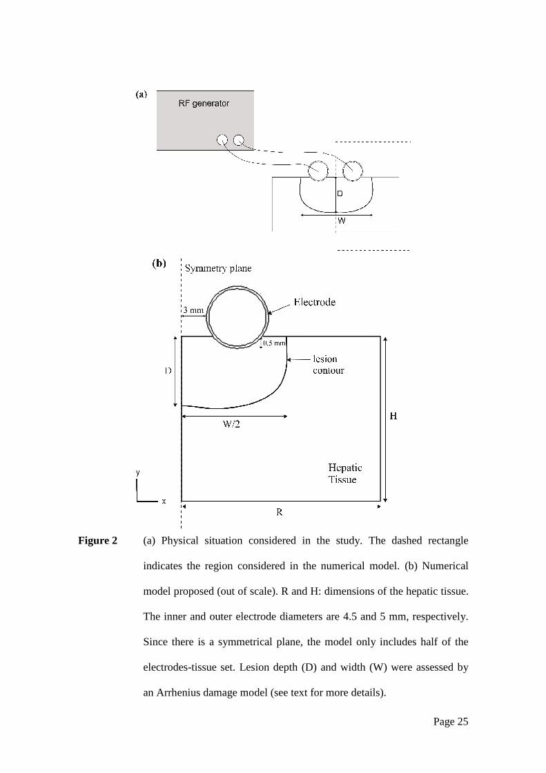
Fig. 2 shows the physical situation modeled and the proposed numerical model,
which represents the device over a fragment of hepatic tissue. Since there is a
symmetrical plane, the model only includes half of the electrodes-tissue set. The
electrode, which has the same diameter as the device used in the experiments (Fig. 1),
was assumed to be inserted in the tissue to a depth of 0.5 mm and was separated from
the symmetrical plane by 3 mm (6 mm inter-electrode distance).
Tissue dimensions R and H were estimated by means of a convergence test in order
to avoid boundary effects, using as control parameter the value of the maximal
temperature achieved in the tissue (Tmax) after 60 s of heating. We first considered a
tentative spatial (i.e. minimum meshing size) and temporal resolution. To determine the
appropriate values of R and H, we conducted a computer analysis by increasing the
value of these parameters by equal amounts. When the difference between Tmax and the
same parameter in the previous simulation was less than 0.5%, we considered the
former values of R and H to be adequate. We then determined adequate spatial and
temporal resolution by means of other convergence tests using the same control
parameter as in the previous test. Discretization was spatially heterogeneous: the finest
zone was always the electrode-tissue interface, since it is known that this has the largest
voltage gradient and hence the maximum value of current density. In the tissue, grid
size was increased gradually with distance from the electrode-tissue interface. The
optimum spatial discretization was achieved by refining the mesh in this zone so that
Page 10
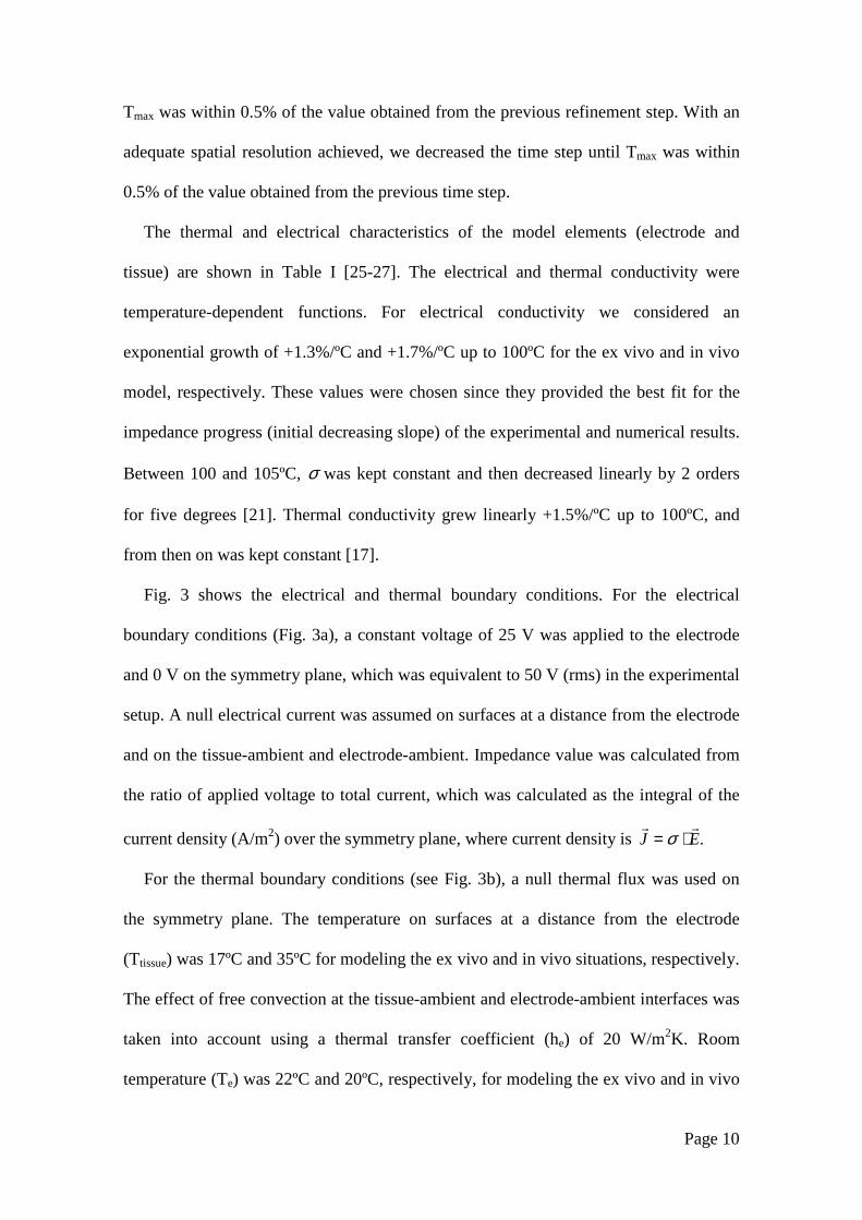
Tmax was within 0.5% of the value obtained from the previous refinement step. With an
adequate spatial resolution achieved, we decreased the time step until Tmax was within
0.5% of the value obtained from the previous time step.
The thermal and electrical characteristics of the model elements (electrode and
tissue) are shown in Table I [25-27]. The electrical and thermal conductivity were
temperature-dependent functions. For electrical conductivity we considered an
exponential growth of +1.3%/ºC and +1.7%/ºC up to 100ºC for the ex vivo and in vivo
model, respectively. These values were chosen since they provided the best fit for the
impedance progress (initial decreasing slope) of the experimental and numerical results.
Between 100 and 105ºC, σ was kept constant and then decreased linearly by 2 orders
for five degrees [21]. Thermal conductivity grew linearly +1.5%/ºC up to 100ºC, and
from then on was kept constant [17].
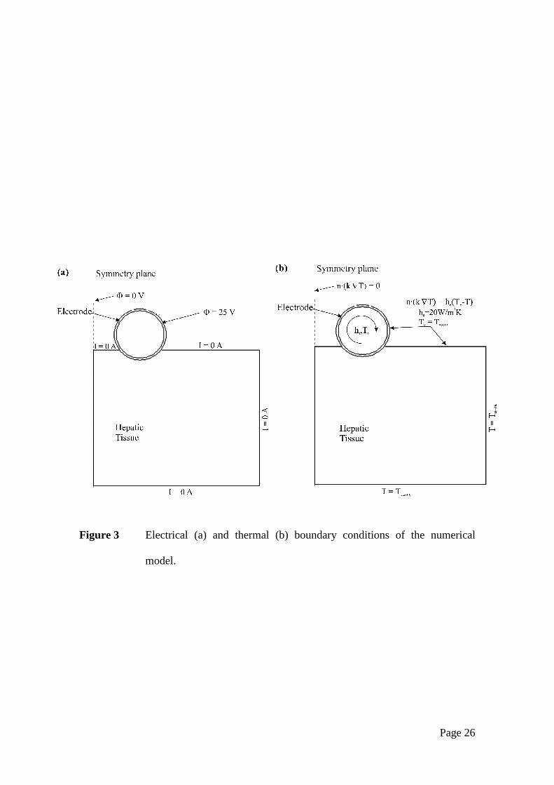
Fig. 3 shows the electrical and thermal boundary conditions. For the electrical
boundary conditions (Fig. 3a), a constant voltage of 25 V was applied to the electrode
and 0 V on the symmetry plane, which was equivalent to 50 V (rms) in the experimental
setup. A null electrical current was assumed on surfaces at a distance from the electrode
and on the tissue-ambient and electrode-ambient. Impedance value was calculated from
the ratio of applied voltage to total current, which was calculated as the integral of the
current density (A/m2) over the symmetry plane, where current density is .EJrr
⋅= σ
For the thermal boundary conditions (see Fig. 3b), a null thermal flux was used on
the symmetry plane. The temperature on surfaces at a distance from the electrode
(Ttissue) was 17ºC and 35ºC for modeling the ex vivo and in vivo situations, respectively.
The effect of free convection at the tissue-ambient and electrode-ambient interfaces was
taken into account using a thermal transfer coefficient (he) of 20 W/m2K. Room
temperature (Te) was 22ºC and 20ºC, respectively, for modeling the ex vivo and in vivo
Page 11
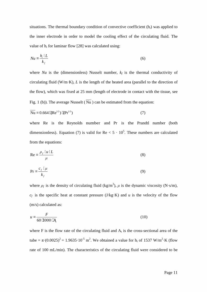
situations. The thermal boundary condition of convective coefficient (hi) was applied to
the inner electrode in order to model the cooling effect of the circulating fluid. The
value of hi for laminar flow [28] was calculated using:
f
i
k
LhNu
⋅= (6)
where Nu is the (dimensionless) Nusselt number, kf is the thermal conductivity of
circulating fluid (W/m·K), L is the length of the heated area (parallel to the direction of
the flow), which was fixed at 25 mm (length of electrode in contact with the tissue, see
Fig. 1 (b)). The average Nusselt (Nu ) can be estimated from the equation:
)(Pr)(Re0.664Nu 1/31/2 ⋅⋅= (7)
where Re is the Reynolds number and Pr is the Prandtl number (both
dimensionless). Equation (7) is valid for Re < 5 · 105. These numbers are calculated
from the equations:
µ
Luρ f ⋅⋅=Re (8)
f
f
k
µc ⋅=Pr (9)
where ρf is the density of circulating fluid (kg/m3), µ is the dynamic viscosity (N·s/m),
cf is the specific heat at constant pressure (J/kg·K) and u is the velocity of the flow
(m/s) calculated as:
tA
Fu
⋅⋅=
100060 (10)
where F is the flow rate of the circulating fluid and At is the cross-sectional area of the
tube = π·(0.0025)2 = 1.9635·10-5 m2. We obtained a value for hi of 1537 W/m2·K (flow
rate of 100 mL/min). The characteristics of the circulating fluid were considered to be
Page 12
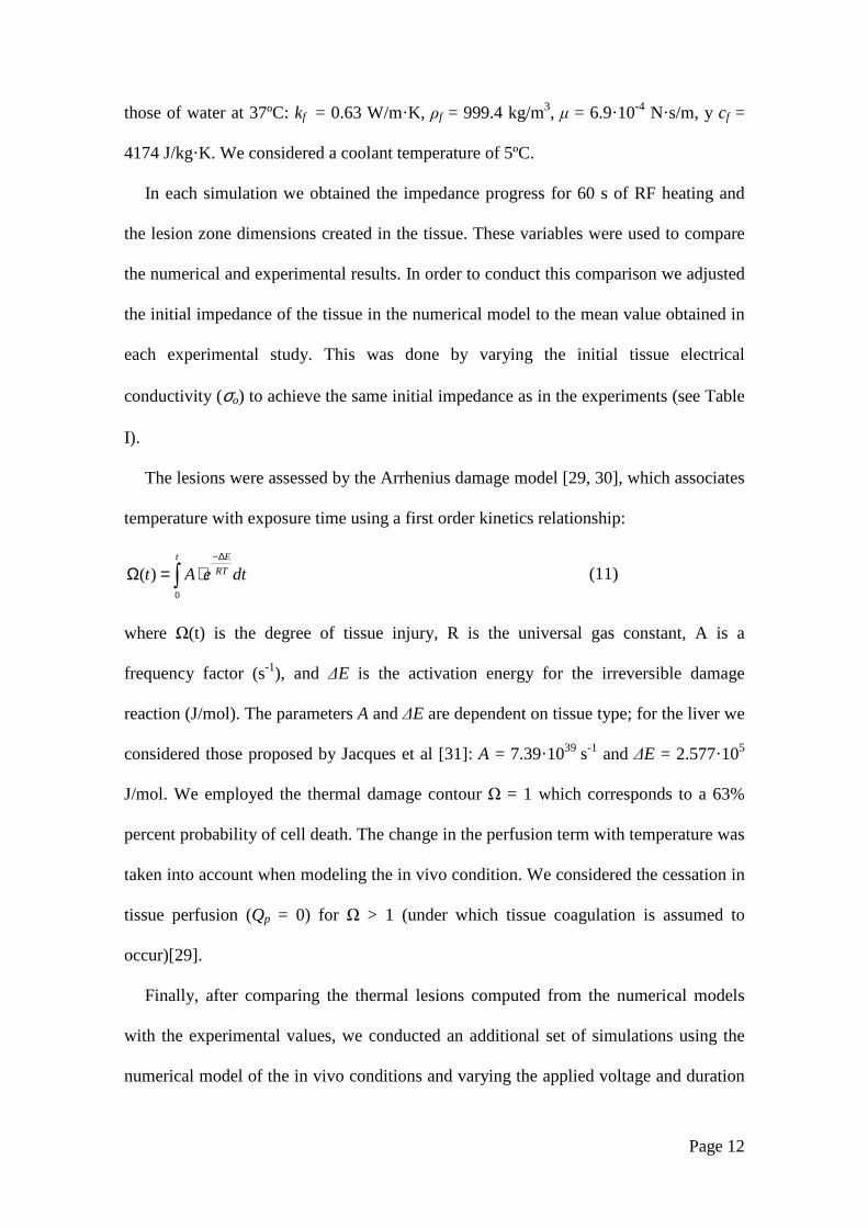
those of water at 37ºC: kf = 0.63 W/m·K, ρf = 999.4 kg/m3, µ = 6.9·10-4 N·s/m, y cf =
4174 J/kg·K. We considered a coolant temperature of 5ºC.
In each simulation we obtained the impedance progress for 60 s of RF heating and
the lesion zone dimensions created in the tissue. These variables were used to compare
the numerical and experimental results. In order to conduct this comparison we adjusted
the initial impedance of the tissue in the numerical model to the mean value obtained in
each experimental study. This was done by varying the initial tissue electrical
conductivity (σo) to achieve the same initial impedance as in the experiments (see Table
I).
The lesions were assessed by the Arrhenius damage model [29, 30], which associates
temperature with exposure time using a first order kinetics relationship:
dteAtt
RT
E
∫∆−
⋅=Ω0
)( (11)
where Ω(t) is the degree of tissue injury, R is the universal gas constant, A is a
frequency factor (s-1), and ∆E is the activation energy for the irreversible damage
reaction (J/mol). The parameters A and ∆E are dependent on tissue type; for the liver we
considered those proposed by Jacques et al [31]: A = 7.39·1039 s-1 and ∆E = 2.577·105
J/mol. We employed the thermal damage contour Ω = 1 which corresponds to a 63%
percent probability of cell death. The change in the perfusion term with temperature was
taken into account when modeling the in vivo condition. We considered the cessation in
tissue perfusion (Qp = 0) for Ω > 1 (under which tissue coagulation is assumed to
occur)[29].
Finally, after comparing the thermal lesions computed from the numerical models
with the experimental values, we conducted an additional set of simulations using the
numerical model of the in vivo conditions and varying the applied voltage and duration
Page 13
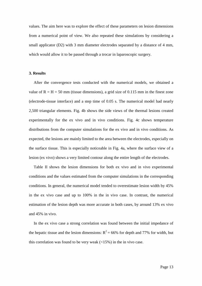
values. The aim here was to explore the effect of these parameters on lesion dimensions
from a numerical point of view. We also repeated these simulations by considering a
small applicator (D2) with 3 mm diameter electrodes separated by a distance of 4 mm,
which would allow it to be passed through a trocar in laparoscopic surgery.
3. Results
After the convergence tests conducted with the numerical models, we obtained a
value of R = H = 50 mm (tissue dimensions), a grid size of 0.115 mm in the finest zone
(electrode-tissue interface) and a step time of 0.05 s. The numerical model had nearly
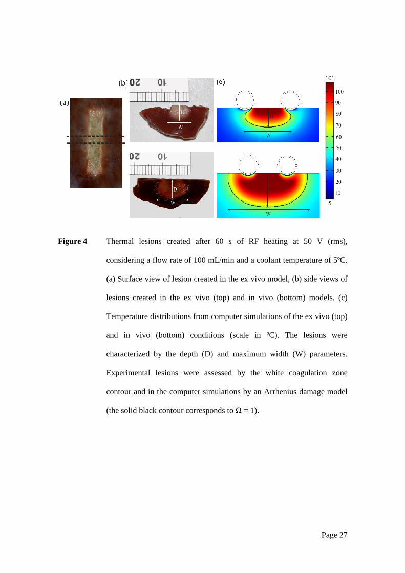
2,500 triangular elements. Fig. 4b shows the side views of the thermal lesions created
experimentally for the ex vivo and in vivo conditions. Fig. 4c shows temperature
distributions from the computer simulations for the ex vivo and in vivo conditions. As
expected, the lesions are mainly limited to the area between the electrodes, especially on
the surface tissue. This is especially noticeable in Fig. 4a, where the surface view of a
lesion (ex vivo) shows a very limited contour along the entire length of the electrodes.
Table II shows the lesion dimensions for both ex vivo and in vivo experimental
conditions and the values estimated from the computer simulations in the corresponding
conditions. In general, the numerical model tended to overestimate lesion width by 45%
in the ex vivo case and up to 100% in the in vivo case. In contrast, the numerical
estimation of the lesion depth was more accurate in both cases, by around 13% ex vivo
and 45% in vivo.
In the ex vivo case a strong correlation was found between the initial impedance of
the hepatic tissue and the lesion dimensions: R2 = 66% for depth and 77% for width, but
this correlation was found to be very weak (<15%) in the in vivo case.
Page 14
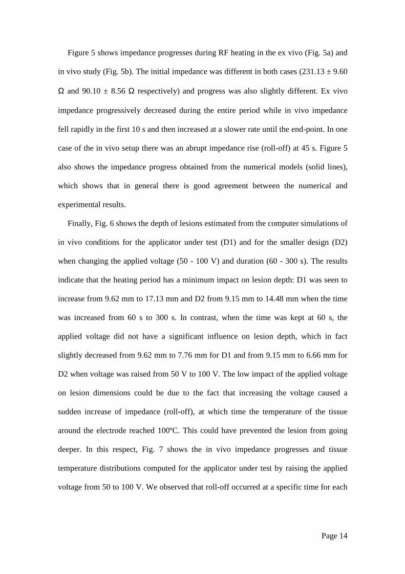
Figure 5 shows impedance progresses during RF heating in the ex vivo (Fig. 5a) and
in vivo study (Fig. 5b). The initial impedance was different in both cases (231.13 ± 9.60
Ω and 90.10 ± 8.56 Ω respectively) and progress was also slightly different. Ex vivo
impedance progressively decreased during the entire period while in vivo impedance
fell rapidly in the first 10 s and then increased at a slower rate until the end-point. In one
case of the in vivo setup there was an abrupt impedance rise (roll-off) at 45 s. Figure 5
also shows the impedance progress obtained from the numerical models (solid lines),
which shows that in general there is good agreement between the numerical and
experimental results.
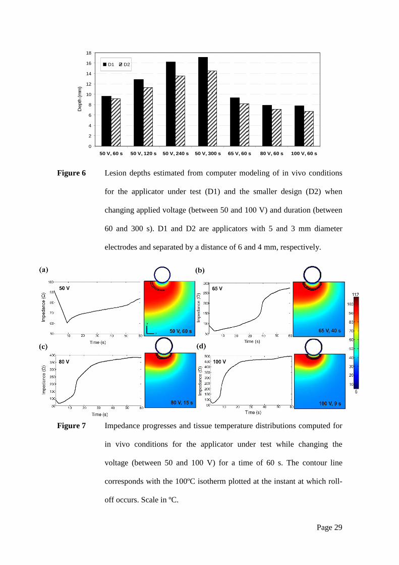
Finally, Fig. 6 shows the depth of lesions estimated from the computer simulations of
in vivo conditions for the applicator under test (D1) and for the smaller design (D2)
when changing the applied voltage (50 - 100 V) and duration (60 - 300 s). The results
indicate that the heating period has a minimum impact on lesion depth: D1 was seen to
increase from 9.62 mm to 17.13 mm and D2 from 9.15 mm to 14.48 mm when the time
was increased from 60 s to 300 s. In contrast, when the time was kept at 60 s, the
applied voltage did not have a significant influence on lesion depth, which in fact
slightly decreased from 9.62 mm to 7.76 mm for D1 and from 9.15 mm to 6.66 mm for
D2 when voltage was raised from 50 V to 100 V. The low impact of the applied voltage
on lesion dimensions could be due to the fact that increasing the voltage caused a
sudden increase of impedance (roll-off), at which time the temperature of the tissue
around the electrode reached 100ºC. This could have prevented the lesion from going
deeper. In this respect, Fig. 7 shows the in vivo impedance progresses and tissue
temperature distributions computed for the applicator under test by raising the applied
voltage from 50 to 100 V. We observed that roll-off occurred at a specific time for each

Page 15
applied voltage and at this time the temperature of the tissue around the electrode was
100ºC: 40 s, 15 s and 9 s for a voltage of 65V, 80 V and 100 V, respectively.
4. Discussion
This study was conducted to assess the capacity of a bipolar cooled RF applicator to
coagulate hepatic tissue and especially to quantify the lesion depths created. We used
three complementary methodologies: ex vivo set up, in vivo experiments and numerical
modeling.
The results of the computer simulations were compared to the experimental results to
assess the accuracy of the numerical models. In general, we observed a tendency in the
computer simulations to overestimate the lesion dimensions. However, we also found
good agreement between the numerical and experimental results of impedance progress,
which suggests that the disagreement could have been due to the method used to assess
the thermal lesion. The experimental lesions were assessed by the white coagulation
zone. Prior to the experimental ex vivo study we evaluated the relationship between the
color change in liver samples immersed in hot water, water temperature, and immersion
time. The samples were heated from 50 to 75ºC for times from 15 to 60 s, as in [32,33].
We observed that the tissue did not turn white until the water temperature reached 70ºC
[34]. Since it is known that temperatures around 50ºC produce coagulative thermal
necrosis, we can state that the experimental lesion dimensions correspond
approximately to the boundary of the 70ºC isotherm, while the lesion dimensions from
the computer simulations using the tissue damage function include a higher amount of
tissue at temperatures over 50ºC. For this reason the lesions estimated from the
numerical models possibly give a truer representation of the dimensions than the white
coagulation contours. Taking the above into account, we consider that the proposed
Page 16
numerical model would be sufficiently accurate if used to study other issues from a
numerical point of view.
In practical terms, the experimental results suggest that by using the closed irrigation
RF bipolar electrode, it is possible to achieve in vivo lesions with a depth ≈7 mm. If the
numerical model gives a more accurate representation of lesion depth, the value could
be around 9 mm. As far as we know, no data have been reported on the lesion depth
achieved by the Aquamantys bipolar system, although there are indications that it is
typically less than 2 mm [35]. The cooled bipolar applicator tested in this study
produces deeper lesions, which could be due to the size of the electrode used (5 mm vs.
3.48 mm in the Aquamantys Model 6.0) and the distance between electrodes (6 mm vs.
2.53 mm). These dimensional differences would undoubtedly have an influence on the
results, as would the different technologies they use: open vs. closed irrigation. Previous
comparative studies on RF cardiac ablation have not been unanimous in their findings;
while some suggest there are no differences between open and closed irrigation at the
same power settings [36], others maintain that there are no differences for power levels
higher than 20 W [5,6] but that closed irrigation produces deeper lesions at low power
setting (< 20 W) [5]. Future studies should be conducted to compare the lesion depths
created by both systems in hepatic tissue.
An experimental study on cardiac tissue using the Isolator device (Atricure,
Cincinnati, OH USA) based on closed irrigation bipolar RF electrodes reported a mean
lesion depth of 5.3 ± 3.0 mm [37]. This shows once again that lesion characteristics are
highly dependent on the electrode design (diameter and distance between electrodes), as
well as other factors such as contact pressure, power delivering protocol (including
power setting), so that a direct comparison with our results is difficult. However, our
findings suggest that the applicator studied would be useful for creating sufficiently
Page 17
deep thermal lesions in hepatic tissue to assist in sealing small vessels during surgical
resection, or producing a long thermal lesion along the transection plane in preparation
for cutting with a cold scalpel.
It should be emphasized that our aim was not to determine the factors affecting the
incidence of steam popping or impedance rise (as in [2]), i.e. we did not search for the
optimum combination of applied voltage and duration. In this respect, the results from
additional computer simulations in which these two parameters were varied suggest that
lengthening the duration could extend lesion depth to 17 mm. They also suggest that
raising the applied voltage will not increase lesion depth. In this regard, we found that at
higher voltages the tissue around the electrode reaches ≈ 100ºC and causes an abrupt
increase of impedance at a specific time. This interrupts the flow of RF current and
consequently limits the size of the lesion. We therefore consider that a value around 50
V would be the optimum.
From a clinical point of view, the applicator tested here is too large to be used in a
laparoscopic approach and hence can only be employed in open surgery for both liver
resection and surface tumor ablation. However, the numerical model proposed here
could be useful for exploring the suitability of other designs for use with a trocar in
laparoscopic surgery. In this respect, the numerical results computed for different values
of applied voltage and duration were similar to previous results. A lesion depth ≈14 mm
could be achieved when the duration is increased. On the other hand, simply raising the
applied voltage did not provide deeper lesions.
This study has certain limitations. Firstly, the numerical model was two-dimensional,
while the experimental models were obviously three-dimensional. The comparison
between the numerical and experimental results suggests that this limitation is not
highly significant, at least for the durations used here, since the edge effect observed in
Page 18
the early stages (when heating is mainly confined to the ends of the electrodes) seems
negligible for heating times longer than 60 s. Also, the in vivo computer simulations
considered only one value for tissue perfusion, although the actual perfusion rate in each
lesion zone was unknown under the specific in vivo experimental conditions.
Finally, the differences between the ex vivo and in vivo results could be due not only
to the different initial impedance and temperature values, but possibly also to whether or
not the Glisson’s capsule had been previously removed. The electrical and thermal
effect of this layer on lesions should be made the subject of further research. Although
its clinical impact seems low, its presence could have caused the steam pops observed in
our in vivo study, due to steam accumulating between the hepatic tissue and capsule
during heating.
5. Conclusions
The experimental results suggest that the cooled bipolar RF applicator tested in this
study could create lesions with a depth around 7 mm under in vivo conditions and that
the thermal lesion is mainly confined to the area between the electrodes, which would
make it possible to control lesion width by selecting a specific applicator design. The
comparison between the experimental and numerical results suggests that the numerical
model could be useful for further studies of the performance of this device.
Acknowledgements
This work received financial support from the Spanish “Plan Nacional de I+D+I del Ministerio de Ciencia
e Innovación” Grant No. TEC2011-27133-C02-(01 and 02), from Universitat Politècnica de València
(INNOVA11-01-5502; and PAID-06-11 Ref. 1988). A. González-Suárez is the recipient of a Grant
VaLi+D (ACIF/2011/194) from the Generalitat Valenciana. The proof-reading of this paper was funded
by the Universitat Politècnica de València, Spain.

Page 19
References
[1] Topp SA, McClurken M, Lipson D, Upadhya GA, Ritter JH, Linehan D, Strasberg SM. Saline-
linked surface radiofrequency ablation: factors affecting steam popping and depth of injury in the
pig liver. Ann Surg 2004; 239(4):518-27.
[2] Gnerlich JL, Ritter JH, Linehan DC, Hawkins WG, Strasberg SM. Saline-linked surface
radiofrequency ablation: a safe and effective method of surface ablation of hepatic metastatic
colorectal cancer. Ann Surg 2009 Jul; 250(1):96-102.
[3] Sakamoto Y, Yamamoto J, Kokudo N, Seki M, Kosuge T, Yamaguchi T, Muto T, Makuuchi M.
Bloodless liver resection using the monopolar floating ball plus ligasure diathermy: preliminary
results of 16 liver resections. World J Surg 2004 Feb; 28(2):166-72.
[4] Poon RT, Fan ST, Wong J. Liver resection using a saline-linked radiofrequency dissecting sealer
for transection of the liver. J Am Coll Surg 2005 Feb; 200(2):308-13.
[5] Everett TH 4th, Lee KW, Wilson EE, Guerra JM, Varosy PD, Olgin JE. Safety profiles and lesion
size of different radiofrequency ablation technologies: a comparison of large tip, open and closed
irrigation catheters. J Cardiovasc Electrophysiol 2009 Mar; 20(3):325-35.
[6] Yokoyama K, Nakagawa H, Wittkampf FH, Pitha JV, Lazzara R, Jackman WM. Comparison of
electrode cooling between internal and open irrigation in radiofrequency ablation lesion depth and
incidence of thrombus and steam pop. Circulation 2006 Jan 3; 113(1):11-9.
[7] Demazumder D, Mirotznik MS, Schwartzman D. Comparison of irrigated electrode designs for
radiofrequency ablation of myocardium. J Interv Card Electrophysiol 2001 Dec; 5(4):391-400.
[8] Cooper JM, Sapp JL, Tedrow U, Pellegrini CP, Robinson D, Epstein LM, Stevenson WG.
Ablation with an internally irrigated radiofrequency catheter: learning how to avoid steam pops.
Heart Rhythm 2004 Sep; 1(3):329-33.
[9] Burdío F, Grande L, Berjano E, Martinez-Serrano M, Poves I, Burdío JM, Navarro A, Güemes A.
A new single-instrument technique for parenchyma division and hemostasis in liver resection: a
clinical feasibility study. Am J Surg 2010 Dec; 200(6):e75-80.
[10] Ríos JS, Zalabardo JM, Burdio F, Berjano E, Moros M, Gonzalez A, Navarro A, Güemes A.
Single instrument for hemostatic control in laparoscopic partial nephrectomy in a porcine model
without renal vascular clamping. J Endourol 2011 Jun;25(6):1005-11.
Page 20
[11] Dorcaratto D, Burdío F, Fondevila D, Andaluz A, Poves I, Martinez MA, Quesada R, Berjano E,
Grande L. Laparoscopic distal pancreatectomy: feasibility study of radiofrequency-assisted
transection in a porcine model. J Laparoendosc Adv Surg Tech A 2012 Apr; 22(3):242-8.
[12] Zeh A, Messer J, Davis J, Vasarhelyi A, Wohlrab D. The Aquamantys system-an alternative to
reduce blood loss in primary total hip arthroplasty? J Arthroplasty 2010; 25(7):1072-7.
[13] Wattiez A, Khandwala S, Bruhat MA. Electrosurgery in Operative Endoscopy. Hoboken, New
Jersey, Wiley-Blackwell, 1995.
[14] Sprunger J, Herrell SD. Partial laparoscopic nephrectomy using monopolar saline-coupled
radiofrequency device: Animal model and tissue effect characterization. J Endourol 2005; 19:513–
519.
[15] Voeller RK, Zierer A, Lall SC, Sakamoto S, Schuessler RB, Damiano RJ. Efficacy of a novel
bipolar radiofrequency ablation device on the beating heart for atrial fibrillation ablation: a long-
term porcine study. J Thorac Cardiovasc Surg 2010; 140(1):203-8.
[16] Pai M, Spalding D, Jiao L, Habib N. Use of bipolar radiofrequency in parenchymal transection of
the liver, pancreas and kidney. Dig Surg. 2012; 29(1):43-7.
[17] Berjano EJ. Theoretical modeling of epicardial radiofrequency ablation: state-of-the-art and
challenges for the future. Biomed Eng Online 2006; 5:24.
[18] Tungjitkusolmun S, Staelin ST, Haemmerich D, Tsai JZ, Webster JG, Lee FT Jr, Mahvi DM,
Vorperian VR. Three-dimensional finite element analyses for radio-frequency hepatic tumor
ablation. IEEE Trans Biomed Eng 2002; 49 (1):3-9.
[19] Doss JD. Calculation of electric fields in conductive media. Med Phys 1982; 9(4):566-73.
[20] Abraham JP, Sparrow EM. A thermal-ablation bioheat model including liquid-to-vapor phase
change, pressure- and necrosis-dependent perfusion, and moisture-dependent properties. Int J Heat
Mass Tran 2007; 50(13-14):2537-44.
[21] Byeongman J, Alptekin A. Prediction of the extent of thermal damage in the cornea during
conductive keratoplasty. J Therm Biol 2010; 35(4):167-74.
[22] Pearce J, Panescu D, Thomsen S. Simulation of diopter changes in radio frequency conductive
keratoplasy in the cornea. WIT Trans Biomed Health 2005; 8: 469-77.
[23] Yang D, Converse MC, Mahvi DM, Webster JG. Expanding the bioheat equation to include tissue
internal water evaporation during heating. IEEE Trans Biomed Eng 2007; 54: 1382-8.
Page 21
[24] Zhao G, Zhang HF, Guo XJ, Luo DW, Gao DY. Effect of blood flow and metabolism on
multidimensional heat transfer during cryosurgery. Med Eng Phys 2007; 29: 205-15.
[25] Pätz T, Körger T, Preusser T. Simulation of Radiofrequency Ablation Including Water
Evaporation. IFMBE Procedings 25/IV of World Congress on Medical Physics and Biomedical
Engineering 2009; 1287-90.
[26] Berjano EJ, Burdío F, Navarro AC, Burdío JM, Güemes A, Aldana O, Ros P, Sousa R, Lozano R,
Tejero E, Gregorio MA. Improved perfusion system for bipolar radiofrequency ablation of liver.
Physiol Meas 2006; 27(10):55-66.
[27] Duck F. Physical properties of tissue - A comprehensive reference book. New York: Academic
Press, 1990.
[28] Burdío F, Berjano EJ, Navarro A, Burdío JM, Grande L, Gonzalez A, Cruz I, Güemes A, Sousa R,
Subirá J, Castiella T, Poves I, Lequerica JL. Research and development of a new RF-assisted
device for bloodless rapid transection of the liver: Computational modeling and in vivo
experiments. Biomed Eng Online 2009; 8:6.
[29] Chang IA. Considerations for thermal injury analysis for RF ablation devices. Open Biomed Eng J
2010; 4:3-12.
[30] Chang I, Nguyen U. Thermal modelling of lesion growth with radiofrequency ablation devices.
Biomed Eng Online 2004; 3(1):27.
[31] Jacques S, Rastegar S, Thomsen S, Motamedi M. The role of dynamic changes in blood perfusion
and optical properties in laser coagulation of tissue. IEEE J Sel Top Quantum Electron 1996;
2:922-33.
[32] Panescu D, Whayne JG, Fleischman SD, Mirotznik MS, Swanson DK, Webster JG. Three-
dimensional finite element analysis of current density and temperature distributions during radio-
frequency ablation. IEEE Transsactions on Biomedical Engineering 1995; 42(9):879-90.
[33] Dadd JS, Ryan TP, Platt R. Tissue impedance as a function of temperature and time. Biomed Sci
Instrum 1996; 32:205-14.
[34] González-Suárez A, Alba J, Trujillo M, Berjano E. Experimental and theoretical study of an
internally cooled bipolar electrode for RF coagulation of biological tissues. Conf Proc IEEE Eng
Med Biol Soc 2011; 6878-81.
Page 22
[35] Rosenberg AG. Reducing blood loss in total joint surgery with a saline-coupled bipolar sealing
technology. J Arthroplasty 2007 Jun;22(4 Suppl 1):82-5.
[36] Petersen HH, Roman-Gonzalez J, Johnson SB, Hastrup Svendsen J, HaunsØ S, Packer DL.
Mechanisms for enlarging lesion size during irrigated tip radiofrequency ablation: is there a virtual
electrode effect? J Interv Cardiol 2004 Jun;17(3):171-7.
[37] Voeller RK, Zierer A, Lall SC, Sakamoto S, Schuessler RB, Damiano RJ Jr. Efficacy of a novel
bipolar radiofrequency ablation device on the beating heart for atrial fibrillation ablation: a long-
term porcine study. J Thorac Cardiovasc Surg 2010 Jul;140(1):203-8.
Page 23
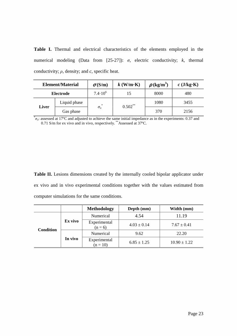
Table I. Thermal and electrical characteristics of the elements employed in the
numerical modeling (Data from [25-27]): σ, electric conductivity; k, thermal
conductivity; ρ, density; and c, specific heat.
Element/Material σσσσ (S/m) k (W/m·K) ρρρρ (kg/m3) c (J/kg·K)
Electrode 7.4·106 15 8000 480
Liquid phase 1080 3455
Liver Gas phase
σo* 0.502**
370 2156 *σo: assessed at 17ºC and adjusted to achieve the same initial impedance as in the experiments: 0.37 and
0.71 S/m for ex vivo and in vivo, respectively. ** Assessed at 37ºC.
Table II. Lesions dimensions created by the internally cooled bipolar applicator under
ex vivo and in vivo experimental conditions together with the values estimated from
computer simulations for the same conditions.
Methodology Depth (mm) Width (mm)
Numerical 4.54 11.19 Ex vivo Experimental
(n = 6) 4.03 ± 0.14 7.67 ± 0.41
Numerical 9.62 22.20 Condition
In vivo Experimental (n = 10) 6.85 ± 1.25 10.90 ± 1.22
Page 24
Figure 1 Top (a) and side (b) views of the internally cooled bipolar applicator
proposed to coagulate hepatic tissue.
Page 25
Figure 2 (a) Physical situation considered in the study. The dashed rectangle
indicates the region considered in the numerical model. (b) Numerical
model proposed (out of scale). R and H: dimensions of the hepatic tissue.
The inner and outer electrode diameters are 4.5 and 5 mm, respectively.
Since there is a symmetrical plane, the model only includes half of the
electrodes-tissue set. Lesion depth (D) and width (W) were assessed by
an Arrhenius damage model (see text for more details).
Page 26
Figure 3 Electrical (a) and thermal (b) boundary conditions of the numerical
model.
Page 27
Figure 4 Thermal lesions created after 60 s of RF heating at 50 V (rms),
considering a flow rate of 100 mL/min and a coolant temperature of 5ºC.
(a) Surface view of lesion created in the ex vivo model, (b) side views of
lesions created in the ex vivo (top) and in vivo (bottom) models. (c)
Temperature distributions from computer simulations of the ex vivo (top)
and in vivo (bottom) conditions (scale in ºC). The lesions were
characterized by the depth (D) and maximum width (W) parameters.
Experimental lesions were assessed by the white coagulation zone
contour and in the computer simulations by an Arrhenius damage model
(the solid black contour corresponds to Ω = 1).

Page 28
Figure 5 Impedance progresses during RF heating in the ex vivo (a) and in vivo
study (b). The solid lines show the results of computer simulations of the
corresponding conditions. Both cases (ex vivo and in vivo) consider a
flow rate of 100 mL/min and a coolant temperature of 5ºC. Note that an
in vivo experimental case showed an impedance rise (roll-off) at 45 s.
Page 29
0
2
4
6
8
10
12
14
16
18
50 V, 60 s 50 V, 120 s 50 V, 240 s 50 V, 300 s 65 V, 60 s 80 V, 60 s 100 V, 60 s
Dep
th (m
m)
D1 D2
Figure 6 Lesion depths estimated from computer modeling of in vivo conditions
for the applicator under test (D1) and the smaller design (D2) when
changing applied voltage (between 50 and 100 V) and duration (between
60 and 300 s). D1 and D2 are applicators with 5 and 3 mm diameter
electrodes and separated by a distance of 6 and 4 mm, respectively.
Figure 7 Impedance progresses and tissue temperature distributions computed for
in vivo conditions for the applicator under test while changing the
voltage (between 50 and 100 V) for a time of 60 s. The contour line
corresponds with the 100ºC isotherm plotted at the instant at which roll-
off occurs. Scale in ºC.