Embed Size (px)
Citation preview
RPSEA
FINAL TECHNICAL
REPORT
09121-3500-01.FINAL
Intelligent Production System for Ultra-
Deepwater with Short Hop Wireless Power
and Wireless Data Transfer for Lateral
Production Control and Optimization
09121-3500-01
March 21, 2013
Paulo Tubel
President
Tubel LLC
25907 Oak Ridge Dr.
The Woodlands, TX 77380
i
DISCLAIMER STATEMENT
This report was prepared by Tubel LLC as an account of work sponsored by the Research Partnership to Secure Energy for America, RPSEA. Neither RPSEA members of RPSEA, the National Energy Technology Laboratory, the U.S. Department of Energy, nor any person acting on behalf of any of the entities:
a. MAKES ANY WARRANTY OR REPRESENTATION, EXPRESS OR IMPLIED WITH RESPECT TO ACCURACY, COMPLETENESS, OR USEFULNESS OF THE INFORMATION CONTAINED IN THIS DOCUMENT, OR THAT THE USE OF ANY INFORMATION, APPARATUS, METHOD, OR PROCESS DISCLOSED IN THIS DOCUMENT MAY NOT INFRINGE PRIVATELY OWNED RIGHTS, OR
b. ASSUMES ANY LIABILITY WITH RESPECT TO THE USE OF, OR
FOR ANY AND ALL DAMAGES RESULTING FROM THE USE OF, ANY INFORMATION, APPARATUS, METHOD, OR PROCESS DISCLOSED IN THIS DOCUMENT.
THIS IS AN INTERIM REPORT. THEREFORE, ANY DATA, CALCULATIONS, OR CONCLUSIONS REPORTED HEREIN SHOULD BE TREATED AS PRELIMINARY. REFERENCE TO TRADE NAMES OR SPECIFIC COMMERCIAL PRODUCTS, COMMODITIES, OR SERVICES IN THIS REPORT DOES NOT REPRESENT OR CONSTIITUTE AND ENDORSEMENT, RECOMMENDATION, OR FAVORING BY RPSEA OR ITS CONTRACTORS OF THE SPECIFIC COMMERCIAL PRODUCT, COMMODITY, OR SERVICE.
ii
ABSTRACT The goals of the UDW program are to exploit the UDW resource base and to
convert currently identified (discovered) resources into economic recoverable
(proven) reserves, while protecting the environment, thereby providing the U.S.
consumer with secure and affordable petroleum supplies. The project developed
by Tubel matches all of the RPSEA goals. The following goals were achieved by
the project development:
a) Increasing the production of UDW oil and gas resources by being able to
optimize hydrocarbon production from laterals by deploying control and
monitoring hardware in the laterals that can be controlled from a remote
location at the surface.
b) Reducing the costs to develop and produce such resources by being able
to deploy a system in the wellbore that will transfer power and
communications in the laterals and in the lower completion from the upper
completion wirelessly for the flow control, to optimize hydrocarbon
production and reduce the interventions in the well.
c) Increasing the efficiency of exploitation of such resources by controlling
the production in the laterals so that laterals can be divided into multiple
producing zones, allowing for production from the toe (end) of the well
instead of mostly the heel (entrance) of the lateral. Also, the ability to
monitor water production allows the operator to precisely know the
location of the water production and remotely allows for the shut-in of that
production zone to reduce water processing costs at the surface and
maintain hydrocarbon production.
d) Increasing production efficiency and ultimate recovery of such resources
by controlling the encroachment of water into the production stream, as
well as slowing the movement of water into the producing zone. The
production of water can otherwise quickly replace the production of
hydrocarbons inside the production tubing, decreasing the production
efficiency. The movement of water into the producing zones will ultimately
reduce the amount of hydrocarbons that can be produced from that zone
and thereby shorten well life. This system will improve both the efficiency
and recovery from downhole segments.
e) Improving safety and environmental performance, by minimizing
environmental impacts associated with UDW exploration production by
reducing the number of wells drilled and the number of interventions in
wells. The reduction of the number of wells drilled will be a consequence
of multilateral production, allowing much more efficient productivity, and
the environment will be protected because of fewer boreholes and smaller
surface footprints.
iii
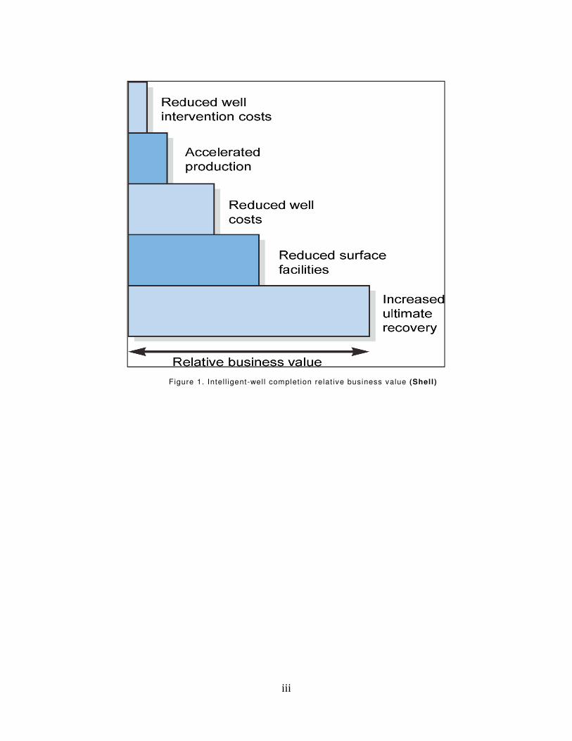
Figure 1. Intel l igent-wel l complet ion relat ive business value (Shell)

iv
Date: February 19, 2013 Created by:
Paulo Tubel Tubel LLC

v
THIS PAGE INTENTIONALLY LEFT BLANK
vi
Description of the Project
The new Intelligent Production System for Ultra-deepwater with Short Hop
Wireless Power and Wireless Data Transfer for Lateral Production Control and
Optimization was developed to provide multilateral wells with a system capable
of optimize production and increase the life of the wells while decreasing the
production costs. The system also allows for data and power to be transferred
from the upper completion to the lower completion, so that gauges and flow
control modules can be deployed closer to the producing zones in the wellbore.
The system is composed of the following modules:
1. Electrically operated flow control system to open, close, or choke the flow
of hydrocarbon from the reservoir into the production tubing. Multiple flow
control systems can be deployed in the horizontal section of the well to
divide it into multiple zones and to equalize the pressure in the lateral. The
equalization will allow for the production from all sections of the lateral
instead of having the production coming from mostly the entrance of the
lateral. The electrical flow control is composed of the following modules:
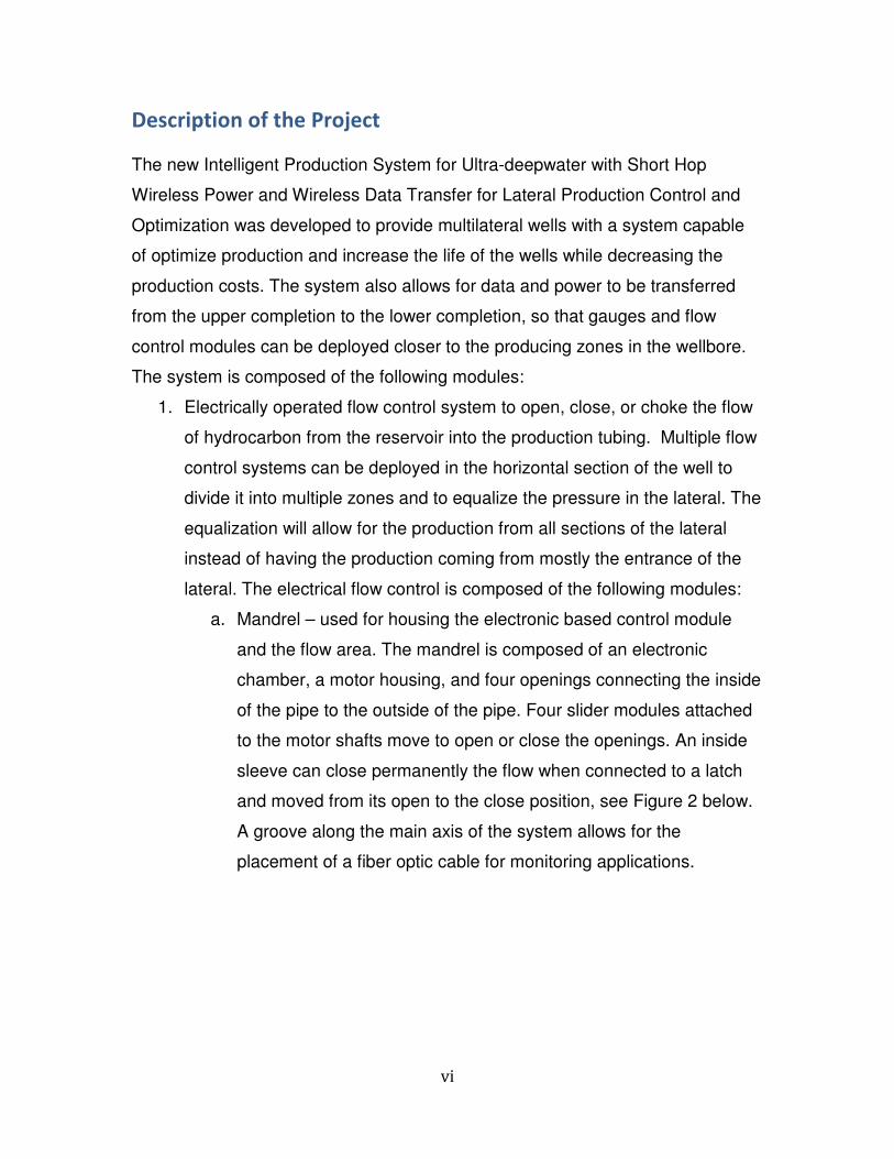
a. Mandrel – used for housing the electronic based control module
and the flow area. The mandrel is composed of an electronic
chamber, a motor housing, and four openings connecting the inside
of the pipe to the outside of the pipe. Four slider modules attached
to the motor shafts move to open or close the openings. An inside
sleeve can close permanently the flow when connected to a latch
and moved from its open to the close position, see Figure 2 below.
A groove along the main axis of the system allows for the
placement of a fiber optic cable for monitoring applications.
vii
Figure 2. Shut-in mechanically operated inner sleeve
b. Extremely Low Power Electronic Module – The system is
composed of five electronic boards: four are used to control the
movement of the four motors and one board is used for power and
communications. The motors operate at 1.2 Watts of power at the
maximum speed and power. The motors are used for opening and
closing sliders to control production. A modem provides the
interface to the electrical cable to receive commands and to
transmit data. Electronic module uses very low power to increase
the life of the components at high temperature and to lower power
consumption.
c. Sleeve sensors – Two pressure and two temperature gauges are
used to provide pressure, temperature, and fluid flow data. The
sapphire gauges provide high accuracy, low power consumption,
and high long term stability.
d. Fluid Identification – Fluid Identification is achieved by having eight
electrodes located around the pipe in the same plane (see Figures
3 and 4). Four electrodes are transmitters and four are receivers.
By transmitting electric current between the electrodes through the
fluid in the pipe, the resistance is measured. The oil is more
resistive than water and will generate a smaller signal.

viii
Figure 3. Schematic for fluid identification tool electrodes
Figure 4. Configuration for electrodes: Red – Transmitter electrodes and white – receiver electrodes
e. Flow meter – Utilizing a small pressure change methodology to
track fluid flow. The pressure detectors are deployed inside and
outside the pipe, and the measurements are made when the flow
control tool is opened. The fluctuations in pressure generated by
the flow in the tubing are converted into flow measurements by the
electronic module in the flow meter module.
2. Communications System – All modules deployed in the laterals and main
bore as well as upper and lower completions have a two-way
communication capability to allow for digital interface between the surface
and downhole for transfer of commands and data, for a complete
Intelligent Well. The system uses a master – slave communication in
which the electronics will drive the electrical cable with Frequency Shift
Keying (FSK) physical layer to transfer data through the cable. The power
on the cable is direct current (DC), and the FSK is added to the DC power.
Serial communication interfaces each downhole module to the
AMPLIFIER /
FILTER STAGE
DAQ
PRE-AMPLIFIER
STAGE
OSCILLATOR
8-Electrode ArrayPermutations: 16

ix
communications module at the surface. The data rate is 1200 bits per
second.
3. Wireless Power and Communications Transfer - A new technology
provides up to two meters of wireless power transfer from the main bore to
the lateral as well as a short hop two-way data transfer to and from the
lateral, as shown in Figure 5. The power transfer provides alternating
current (AC) power in the lateral for the operation of sensors and flow
control systems to optimize production from the laterals. Electromagnetic
mutual resonance technique provides the foundation to the wireless power
transfer method efficiency. The main bore wireless module has an
electronic module to interface to the surface system and drive the
electromagnetic coils that generate the signals and power for the wireless
transfer. The coils are designed to produce a power efficiency of 20
percent during the transfer of energy at a distance of two meters (6 feet).
Figure 5. Power Transfer electrical configuration
4. A cable will be part of the system in each lateral being deployed along the
long axis of the wellbore on the outside of the production tubing. The cable
interfaces to all instrumentation and flow control systems in the lateral. A
cable is also installed in main bore from the surface to near the deepest
lateral in the well. This cable is interfaced to all communications and
x
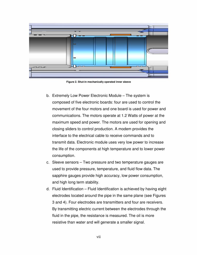
power modules along the main bore. The flow control tool has an internal
cable that goes from the top of the tool to the bottom. The internal cable
interfaces to Kemlon® connectors on top and at the bottom of the tool for
easy cable interface at the well site (see Figure 6). The cable is also
protected from the environment by being inside the tool.
Figure 6. Groove on flow control tool for passing electrical or fiber optic downhole cable
5. A surface system provides the DC power and commands into the well.
The commands are FSK waves that are superimposed on the DC power.
The surface system can also interface to other computers to get
information or transfer data received from the wellbore via RS-485 bus
with MODBUS protocol. The system also monitors for data from
downhole to the surface and for decoding and storing the received data.
The surface system will be composed of a National Electrical
Manufacturers Association explosion proof box, an electronic
microprocessor board which controls and processes the downhole data
and communications through the downhole cable, a keyboard, and an
LCD display for operator to the downhole tools interface.
xi
TABLE OF CONTENTS
DISCLAIMER STATEMENT ................................................................................................................... i
ABSTRACT ................................................................................................................................................. ii
Description of the Project ................................................................................................................... vi
TABLE OF CONTENTS .......................................................................................................................... xi
FIGURES and/or TABLES ...................................................................................................................xii
EXECUTIVE SUMMARY ......................................................................................................................... 1
REPORT DETAILS ................................................................................................................................... 4
Experimental Methods .................................................................................................................. 25
Results and Discussion ...................................................................................................................... 30
Impact to Producers .................................................................................................................. 31
Technology Transfer Efforts .................................................................................................. 33
Conclusions ........................................................................................................................................ 34
Recommendations .......................................................................................................................... 36
xii
FIGURES and/or TABLES
Figure 1. Intelligent-well completion relative business value (Shell) ...........................iii Figure 3. Schematic for fluid identification tool electrodes ............................................ viii Figure 4. Configuration for electrodes: Red – Transmitter electrodes and white – receiver electrodes ............................................................................................................................ viii
Figure 5. Power Transfer electrical configuration ................................................................. ix
Figure 6. Groove on flow control tool for passing electrical or fiber optic downhole cable ............................................................................................................................................................ x
Figure 7. Flow control tool with built in sensors ...................................................................... 8
Figure 8. Design of sensor package for lateral applications .......................................... 14
Figure 9. Power transfer in-line configuration ....................................................................... 19
Figure 10. Power transfer efficiency for lateral transfer ................................................... 20
Figure 11. Configuration of the wireless power and communications for upper and lower completion integration ................................................................................................ 21
Figure 12. Wireless communication module ........................................................................ 22
1 | P a g e
EXECUTIVE SUMMARY
The goals of the UDW program are to exploit the UDW resource base and to
convert currently identified (discovered) resources into economic recoverable
(proven) reserves, while protecting the environment, thereby providing the U.S.
consumer with secure and affordable petroleum supplies. The project being
proposed by Tubel matches all of the RPSEA goals. The following goals have
been achieved by the project development:
a) Increasing the production of UDW oil and gas resources by being able to
optimize hydrocarbon production from laterals through deployment of
control and monitoring hardware in the laterals that can be controlled from
a remote location at the surface.
b) Reducing the costs to develop, and produce such resources by being able
to deploy a system in the wellbore that transfers power and
communications in the laterals and in the lower completion from the upper
completion wirelessly to control and optimize production and reduce the
interventions in the well.
c) Increasing the efficiency of exploitation of such resources by controlling
the production in the laterals so that laterals can be divided into multiple
producing zones, allowing for production from the toe (end) of the well
instead of mostly the heel (entrance) of the lateral. Also, the ability to
monitor water production will allow the operator to precisely know the
location of the water production and remotely shut-in that production zone
to reduce water processing costs at the surface and maintain hydrocarbon
production.
d) Improving safety and environmental performance, by minimizing
environmental impacts associated with UDW exploration production
through reduction in the number of wells drilled and the number of
interventions in wells. The reduction in the number of wells drilled will be a
consequence of multilateral production, allowing for much more efficient
productivity, and the environment will be protected because of fewer
boreholes and smaller surface footprints. The reduction of the number of
interventions in the wells will reduce the chance of accidents that might
affect the safety or inadvertently impact the environment at the well site. It
is important to mention that fewer wells drilled will reduce the risk
associated with well failures, drilling systems getting stuck in wells, gas
kicks, and blowouts.

2 | P a g e
The Intelligent Production System (IPS) can be deployed inside the wells in ultra-
deepwater for remote control of hydrocarbon production. The system can also be
deployed in a lower completion section of a multiple completion well to
electrically connect the upper and lower completions. The Intelligent System for
downhole will help horizontal well production even if multilaterals are not
implemented in the production plan. The system will maximize the extraction of
hydrocarbon from the reservoirs as well as optimize production.
The system features a wireless power transfer system from the main bore into
the laterals to power gauges, flow control systems, and communications
modules. The wireless power transfer provides 20 percent efficiency over a two-
meter distance between the transmitter and receiver modules. A short hop
communications system between the main bore and the lateral(s) provides for
data and commands to be transferred between a remote location at the surface
and the lateral(s).
Sensors acquire real-time status information on the reservoir and production
while monitoring for water production. The low power modules acquire pressure,
temperature, velocity of fluids, flow meter, and fluid identification.
Multiple electrically operated flow control systems can be deployed in the well to
control the hydrocarbon transfer from the reservoir into the production tubing.
Each flow control has an individual address for communications. The flow can be
choked by opening and closing each of the four individual sliders used for
controlling the flow from the annulus into the production tubing.
A master/slave communications capability from the surface into the wellbore
provides the control and communications between the operator and the
downhole modules. The asynchronous communications uses FSK as the means
of communication.
A surface system controls the entire process by sending commands in the well,
receiving and processing the downhole data, and transferring the data to a
remote location. The Intelligent Production System has been developed to be the
next generation of “Smart Wells” and “Intelligent Fields” by both fully
instrumenting the wellbore laterals and providing a surface system that can be
used for data processing as well as for remote data and command transfer.
The surface system has a serial port with Modbus capability to be able to transfer
data from the surface system to a remote computer. The standard protocol

3 | P a g e
allows for the system to interface with virtually all computers operating with
Modbus. The system can also store data in its own memory for transfer upon
request.
4 | P a g e
REPORT DETAILS
The new Intelligent Production System for Ultra-deepwater with Short Hop
Wireless Power and Wireless Data Transfer for Lateral Production Control and
Optimization is a system capable of significantly improving the production
process by providing the means to monitor and control the entire lateral in a well
and also allow for gauges and flow control to be deployed in the lower
completion.
The flow control tool can also be used as a replacement to hydraulic operated
sliding sleeves in the main bore. The system will lower production costs, reduce
risk, and decrease the environmental impact of drilling and producing
hydrocarbons. The development of the project will allow for the construction of a
system composed of the following modules:
1. An electronically controlled and actuated flow control system.
2. Downhole lateral instrumentation.
3. Main bore wireless power and communications transfer module.
4. A wireless power and communications module for lateral installation.
5. Downhole tubing encapsulated cable.
6. Surface Control and Data Acquisition system.
Electronically Controlled and Actuated Flow Control System
The tasks required to create this new Electronically Controlled and Actuated Flow
Control System follow:
Research – The major research work was related to acquiring the best
material for use downhole, specifically strength of the material to provide
as large an internal diameter (ID) and as small an outside diameter (OD)
as feasible. The material chosen for this application was 17-4 stainless
steel. Interfacing with operating companies such as Shell allowed Tubel
LLC to obtain information that was useful in creating the specifications for
the flow control design. A differential pressure of 5000 psi was chosen

5 | P a g e
based on downhole pressures, and the ID and OD were also determined
with additional support from Shell. The ID of 3.8 inches and OD of 7.1
inches were determined to be acceptable by the customers. The original
flow rate was specified at 20,000 barrels per day, but a request from Shell
for 110,000 barrels per day for applications in fracturing work resulted in
changes to the design specifications. The communications system was
chosen to use a standard FSK technique to provide a reliable method of
communications downhole that is fairly immune to cable and downhole
noise. The communications data communications rate was also chosen to
be a standard 1200 Hertz (Hz).
The power consumption for the tool was also evaluated, and the electronic
module specifications required that the power consumption be less than
one milli-Ampere, so that the tool would dissipate a minimal amount of
heat downhole. Also, the specification was influenced by BP Alaska, since
the company wanted to utilize the tool for battery powered applications
with no cable in the well.
Development – The work required for the development of the system
included the design of the electronically based module to control the
opening and closing of the sleeve, data acquisition for the sensors, and
communications via downhole cable. The electronics includes a
microprocessor-based data acquisition, command, control, and
communications module. The module also includes four motor driver
boards to control the four motors in the tool.
The decision was made to integrate the sensors as part of the flow control
tool. Pressure, temperature, and flow meter sensing were added to the
design of the system. The data acquisition for the sensors was
incorporated into the command, control, and communications (3C) board.
The pressure sensors were based on a sapphire design that allows for the
6 | P a g e
sapphire portion of the gauge to be in contact with the well fluid for a more
accurate pressure measurement. The sensors monitored inside and
outside pressures, allowing for the determination of flow when the
differential pressure across the flow control opening is acquired. The 3C
circuits are fully protected against electrical spikes that may be generated
in the cable, and the board also has a fuse installed at the cable junction
to allow for the shutdown of the flow control tool if it pulls an excessive
amount of electrical power - normally a result of a short circuit or a
component failure. These types of failures can cause the entire network of
tools downhole to stop functioning. By disconnecting the failed tool from
the network, the communications system will continue to operate
downhole.
The electronic modules controlling the motors are also fully protected
against electrical spikes. The motor driver boards also monitor the
electrical current being consumed by the motors. The system shuts down
the motor operation if an excessive amount of current is detected at the
motor.
The development of the mandrel was the most important and most difficult
segment of the project. Finite element analysis was performed to ensure
that the system would be able to meet burst and collapse pressures in the
wellbore. The addition of a mechanical sleeve to close the flow path from
the annulus to the tubing reduced the wall thickness in the flow control tool
significantly, thus requiring a new material hardening standard to provide
the strength of material. The motor diameter of 0.4 inches also created a
challenge for the system to withstand the downhole pressures.
Furthermore, the concentricity of the motors and drive shafts was another
important design parameter.

7 | P a g e
The reduction of friction on the sliders by using a special coating over the
metal allowed for the reduction in the motor power consumption and
potentially increased the life of the sliders. Special T-seals were
developed for Tubel LLC to withstand the movement of the sliders over
the seals and maintain the integrity and ability to seal the tool.
The system has a pressure balance feature in which the pressure inside
and outside the tool are balanced to allow for a simpler operation of the
sliders. A piston that is inside the tool senses the pressure inside and
outside and moves one way or the other to maintain the system pressure
balanced.
The operation of the system is described as follows:
• The system will be in a sleep mode awaiting a wake up signal from
the surface or from the system installed at the lateral.
• The microprocessor which will wake up upon receiving a message,
will verify the address of the incoming command.
• Once the proper connection is made, the processor will decode the
command following the address.
• The processor will be highly integrated, having an analog to digital
converter, memory, and processor built into a single chip.
• If the command to open/close the sleeve is received the processor
will signal one of the motor driver board modules, composed of
transistors and a DC motor to drive a shaft attached to the slider.
• The processor will signal the surface when the operation is
completed.
• When the system receive data from the laterals, then the 3C board
will configure the data to be transmitted to the surface via the
electrical cable.
In certain applications the operator wants the flow control module to be
fully integrated with the sensors so the system will monitor the sensors
and acquire data as fast as one sample per second. Data are stored in

8 | P a g e
memory and transmitted to the surface as packets, i.e., multiple data
samples are simultaneously transmitted. Figure 7 shows the tool.
Figure 7. Flow control tool with built in sensors
Integration – the complete system was integrated in the lab to allow he
electronics module and mechanical flow control to function as one unit.
The control electronics and motor drivers were interfaced to the motor and
mechanical driver units to operate the sliders. The communications
section of the 3C module was tested with a single conductor cable
simulator to transfer commands to the flow control tool and obtain data
from the sensors. The electronic module was also mounted on the
mandrel using Sylgard® rubber pads to ensure that the boards were not
stressed due to the curvature of the mandrel. New hardware was
developed to allow oil injection in the tool so that the pressure balance
system can operate properly.
9 | P a g e
Once the flow control was fully assembled, the surface system was
interfaced to the flow control to ensure that the commands and data were
being properly transferred.
There were quite a few issues that had to be addressed during the system
interface. The sliders had to be coated to reduce friction, which reduced
the power required to open and close the tool. The ring that holds the
mechanical sleeve to close the tool permanently was redesigned to allow
the ring to expand once it reached the proper location to hold the sleeve.
The shaft length for the motor driver interface to the motor had to be
increased to permit the slider to travel the entire length of the opening in
the tool.
There were some problems with the electronic system during the
integration of the system. The power converter module had to be modified
to provide protection for the input to prevent high voltage from damaging
the converter. The motor drivers were also modified to protect the driver
circuit from failure due to fly back current, which occurs when the motors
are turned off. A tank circuit was also added to the driver circuit to absorb
the fly back current.
The surface system had to be modified once the test results indicated that
the timing was not correct during the transmission of data that was
recorded in the tool memory after the motors were actuated. Since there
were no data transmission during the motor actuation the data acquired
was stored in memory. Once the motor actuation was completed, then the
tool dumped its memory to the surface. The surface system software was
modified to obtain larger data frames due to the memory stored in the tool
memory. A local LCD display and a keyboard were added to the surface
system to allow the system to send commands in the well without a
personal computer (PC) being attached to the surface system.

10 | P a g e
System test – The Flow Control System was temperature and pressure
tested. Among the tests performed was a motor actuation test at 125
degrees Celsius. The motor was assembled in a module that provided a
resistance to the movement of the slider. The entire assembly was placed
in an oven and operated continuously for 30 days with a complete travel
time of the slider of 30 seconds. The motor was actuated approximately
86,000 times under temperature and resistance without a failure. A flow
loop test was performed to determine the amount of erosion at the
openings of the flow control tool. A heater band was installed on the
outside of the tool to heat up the tool. A pressure differential was exerted
in the system to monitor the performance of the sliders for opening and
closing the system under a differential pressure. The system worked well
and no degradation of the system occurred due to temperature or
pressure.
The Flow Control Tool is a 7-1/8” O.D. downhole tool to be coupled in a
4.5” casting/ production string for oil and gas wells. Its main purpose is to
provide the operator with the ability to open, close or choke fluid
communication between the tubing and annulus. This testing procedure
contains phases two and three, which will aim to confirm the system
functionality, verify that specifications are met, help in predicting field test
results, and provide valuable information for further improvement. The
purpose of this test is to verify the functionality of the electrical and
mechanical components of the tool in an in-situ environment. The in-situ
environment is mimicking the downhole environment. The tests are
discussed in detail below.
1.1 Static Pressure and Temperature Testing
Tubing and Annulus Pressure
Internal pressure: 5,000 +0/-500 psi
External pressure: 5,000 +0/-500 psi
Cycle Pressure two times
Hold pressure at maximum for 30 minutes
11 | P a g e
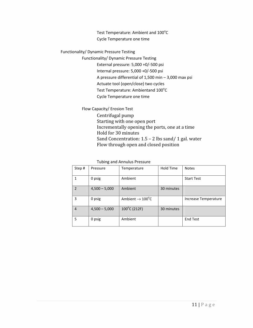
Test Temperature: Ambient and 100oC
Cycle Temperature one time
Functionality/ Dynamic Pressure Testing
Functionality/ Dynamic Pressure Testing
External pressure: 5,000 +0/-500 psi
Internal pressure: 5,000 +0/-500 psi
A pressure differential of 1,500 min – 3,000 max psi
Actuate tool (open/close) two cycles
Test Temperature: Ambientand 100oC
Cycle Temperature one time
Flow Capacity/ Erosion Test
Centrifugal pump
Starting with one open port
Incrementally opening the ports, one at a time
Hold for 30 minutes
Sand Concentration: 1.5 – 2 lbs sand/ 1 gal. water
Flow through open and closed position
Tubing and Annulus Pressure
Step # Pressure Temperature Hold Time Notes
1 0 psig Ambient Start Test
2 4,500 – 5,000 Ambient 30 minutes
3 0 psig Ambient → 100oC Increase Temperature
4 4,500 – 5,000 100oC (212F) 30 minutes
5 0 psig Ambient End Test

12 | P a g e
Functionality/ Dynamic Pressure Test Procedure
Cycle # Step # Tool position Action
1
1 Closed Pressure up Internally to 4,500 – 5,000psi
2 Closed Pressure up Externally to have a pressure
differential of 1,500 min to 3,000 max
3 Closed > Open Actuate Tool from closed position to open
position. Internal Pressure equalizes with
external pressure
4 Open > Closed Actuate tool to the closed position
2
1 Closed Pressure up Internally to 4,500 – 5,000psi
2 Closed Pressure up Externally to have a pressure
differential of 1,500 min to 3,000 max
3 Closed > Open Actuate Tool from closed position to open
position. Internal Pressure equalizes with
external pressure
4 Open > Closed Actuate tool to the closed position
1.1.1 Flow Capacity / Erosion Test Procedure
Fluid Type: 1.5lbs sand/ 1 gal. water
Step # Action
1 Connect the toll to the centrifugal pump using the LTC – NPT
crossover
2 Start with one open port on the tool
3 Hold for 30 minutes
4 Open second port on the tool
5 Hold for 30 minutes
6 Open third port on the tool
7 Hold for 30 minutes
8 Open Fourth port on the tool
9 Hold for 30 minutes
10 End of Test
Field Work – A commercial job with Shell in which four tools will be placed
in the horizontal section of a well will be performed in April 2013.
Documentation - The required documentation for manufacturing,
operations, and deployment of the system have be created.
Downhole lateral instrumentation

13 | P a g e
The instrumentation for monitoring the operations in the sections of the lateral is
a separate module that will be located adjacent to each flow control tool. The
units will monitor pressure, temperature, flow rates, and water content in each
area of interest. The instrumentation will use unique software to obtain flow and
water content information from the wellbore. The module will provide real time
information when requested from the surface.
Research – The research work related to the gauges was based on the
ability to deploy low power sensors with high reliability and accuracy.
Pressure gauge with low power – The team selected the best pressure
gauge based on accuracy and reliability. The chosen sensor was a
sapphire-based type capable of operation at high temperature (300
degrees Celsius), with both high stability and very simple calibration
capability (employing a linear relationship between temperature and
pressure change).
Flow meter – Multiple technologies are available for flow
measurements downhole. The criteria for choosing the flow
measurement technique were to choose a simple mass flow meter with
fluid velocity capability.
The technique chosen involved two rings of electrodes located at a
fixed distance from each other to provide velocity and fluid
identification. Each ring is composed of eight electrodes: four are
transmitters and four are receivers. The higher the output of the
electrodes, the higher the water content is in the production fluid. The
time it takes for events to occur between the two sets of rings provides
the total fluid velocity.
Development – The development of the instrumentation module was
based on the results obtained from the research work. The system
combines all the sensors in a single mandrel, as depicted in Figure 8. The

14 | P a g e
electronic module similar to the sleeve electronics will control the
acquisition and processing of the data from each sensor and transfer the
data to the surface upon the request from the surface system. The system
can operate on batteries or use the wireless power transfer unit for data
and power transfer.
Figure 8. Design of sensor package for lateral applications
The pressure sensors were temperature tested for long term
application and calibrated using a deadweight tester to achieve
accuracies in the 0.1 percent. A temperature sensor was built in the
pressure sensor to create a small and critical module. The temperature
provides the means to compensate the pressure gauge drift due to
temperature changes in the well. The pressure gauges are always
calibrated with the downhole electronic module to ensure that the
entire gauge system is calibrated and properly compensated. The
temperature sensor can also provide indications of gas flow in the
wellbore.
15 | P a g e
Two clusters of electrode rings were also deployed to monitor changes
in the resistivity of the fluid that could be related to flow. The time for
the resistivity changes from the lower electrode ring to the upper ring
can be measured directly, and, based on the distance between the
rings, fluid velocity and thus flow rate can be calculated. The system
includes pre-amplifiers for each of the four receiver electrodes. A
multiplexer channels each receiver into the data acquisition electronics
to be digitized and stored in memory. The signal levels are quite small
when 100 percent oil is in the well but become very large when water
is in the well.
The tool will contain cable-based communications and/or wireless
communications. Batteries or super capacitors can be used to store
energy. The system is attached to a cable where power and
communications are transferred from the entrance of the lateral to the
systems inside the lateral. The communication method is the same as
the cable communications in the main bore, where FSK
communication is used in a master/slave format to transfer data and
commands.
Integration – All sensors were integrated to the control and
communications module in the laboratory and installed in the
instrumentation mandrel. The system was pressure tested for sensor
leaks, communications tested to ensure that all data would transmit
properly, and temperature tested to determine that the gauges would
perform at the maximum operating temperature.
System Tests – The complete instrumentation system was tested to
monitor pressure, temperature, flow rate, and water content. The system
was tested in a small loop in which different water and oil content was
passed to ensure that the electrode rings were detecting the changes in

16 | P a g e
resistivities and consequently was able to detect the flow rates. The tests
were successful.
Main bore power and communications module
The module is the basis for the entire communications process, both in the
main bore as well as the laterals. The system is installed in most modules in
the well and provides two-way communications from the surface to downhole
as well as to provide communications in the laterals among the lateral tools.
The communications to the surface will be accomplished via an electrical
cable that will have both DC power and digital communications. The power at
the surface will vary from 60 to 100 volts DC, and the communications will
ride above the DC power. The communications in the lateral will be performed
using cables to interface the lateral tools. The communications speed is 1200
bits per second, which is sufficiently fast for most activities in the well. The
interface between the main bore and laterals will be accomplished using a
wireless power and communications module which provides electromagnetic
power over a set of coils using a mutual resonance technique and
electromagnetic communications. An electronic module converts AC power
into 3.0 volts DC for powering the electronics in the tool and also into 12 volts
DC for operation of the motors if a flow control tool is used. The electronics
also filters the DC power so that the communications can be acquired and
decoded.
Research – The main purpose of the research work was to determine a
workable approach for the data communications that could be used in wells at
long distances from host facilities. A FSK communications was chosen in
which 1200 and 2400 Hz are used as equivalent to a digital 1 and 0,
respectively. This technique allows 1200 bits per second to be transmitted in
a single conductor cable in the well. A standard modem communications was
chosen to minimize the development work.

17 | P a g e
Development – The main challenges in the development were:
communications distance between the transmitter and receiver, operating
temperature, and interfaces to the DC power and microprocessor controller in
the tools. The communications distance was tested using a cable simulator
capable of 20,000 feet of standard 18-gauge single conductor cable in the
wellbore. The communications worked well with the driver design, which was
used to drive the cable for the communications signals from the modem. The
communications was temperature tested and worked without a problem at a
20,000-foot distance between the transmitter and receiver. A coupling module
was developed to interface the high DC voltage to the AC modem signal, and
another module was developed to recover the modem signal from the DC
signal. A serial communication package including a software program was
developed to interface the modem to the microprocessor for control of the
system.
Integration – The system was integrated in the laboratory and as part of the
tools. Some of the problems encountered were based on the lack of
protection of the tools. The regulator for each tool was protected with
capacitors and Zener diodes to prevent electrical spikes and noise from
affecting the power regulation from the cable to the electronic module. The
serial communication from the processor to the modem was debugged and
timing for the communications was tested. The communications was
implemented to the flow control tool to integrate the power and
communications to the motor driver system. The system worked well after the
protection features to protect the power system were implemented.
The test results showed that the system works well. High voltage placed on
the cable did not affect the ability to communicate and did not damage the
electronics due to the voltage protection module.
A wireless power and communications module for lateral installation or
lower completion

18 | P a g e
The wireless power and communications module was developed to allow
power and communications to be transferred into areas where power has not
been available in the past. The ability to have power and communications in
the laterals opens new opportunities for control and monitoring in the laterals,
and not just in the main bore.
Research – The work performed by the University of Houston for short hop
power transfer was related to the ability of the system to transfer power over
distance and the efficiency of the transfer in the wellbore environment. The
main goals included the feasibility of the technology and optimization of the
wireless power transfer from a transmitter coil to a receiver coil, operating at a
sufficiently low frequency that the receiver is in the near field of the
transmitter, with radiation effects being negligible. The power transmission
was accomplished by using the mutual coupling between the two coils as the
linking mechanism. An equivalent circuit model was used to analyze and
reveal the basic principles of the wireless power transmission. This was first
done for coils in free space, to help understand the basic principles of
operation. It was necessary to study the feasibility of transferring power
wirelessly via coils placed on a pipe, and to examine the extent to which
power transfer could be achieved with a reasonable efficiency. One of the
additional losses was encountered when the coils were placed on a pipe:
Eddy current losses occurred due to induced current flow in the metal pipe.
Development - The production of hydrocarbons requires the use of power
inside the well to operate flow control devices and gauges. The use of
wireless power transfer is essential for the introduction of power into laterals
from the main bore. The use of mutually resonating coils allows for the long
distance transfer of power and communications at reasonable efficiencies of
20 percent to 30 percent. The system utilizes an electronic module to
resonate the coils at a frequency of approximately 600 KHz to obtain a mutual
resonating power transfer. The electronics modulates the cable power by
19 | P a g e
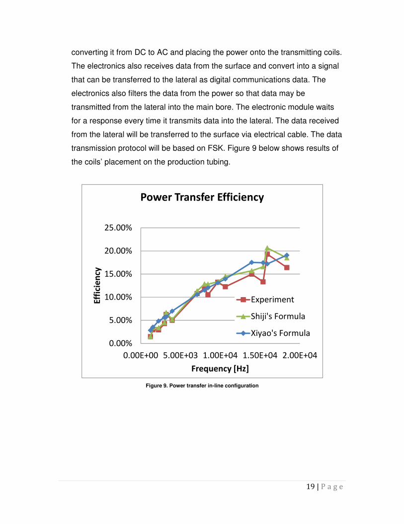
converting it from DC to AC and placing the power onto the transmitting coils.
The electronics also receives data from the surface and convert into a signal
that can be transferred to the lateral as digital communications data. The
electronics also filters the data from the power so that data may be
transmitted from the lateral into the main bore. The electronic module waits
for a response every time it transmits data into the lateral. The data received
from the lateral will be transferred to the surface via electrical cable. The data
transmission protocol will be based on FSK. Figure 9 below shows results of
the coils’ placement on the production tubing.
Figure 9. Power transfer in-line configuration
0.00%
5.00%
10.00%
15.00%
20.00%
25.00%
0.00E+00 5.00E+03 1.00E+04 1.50E+04 2.00E+04
Eff
icie
ncy
Frequency [Hz]
Power Transfer Efficiency
Experiment
Shiji's Formula
Xiyao's Formula
20 | P a g e
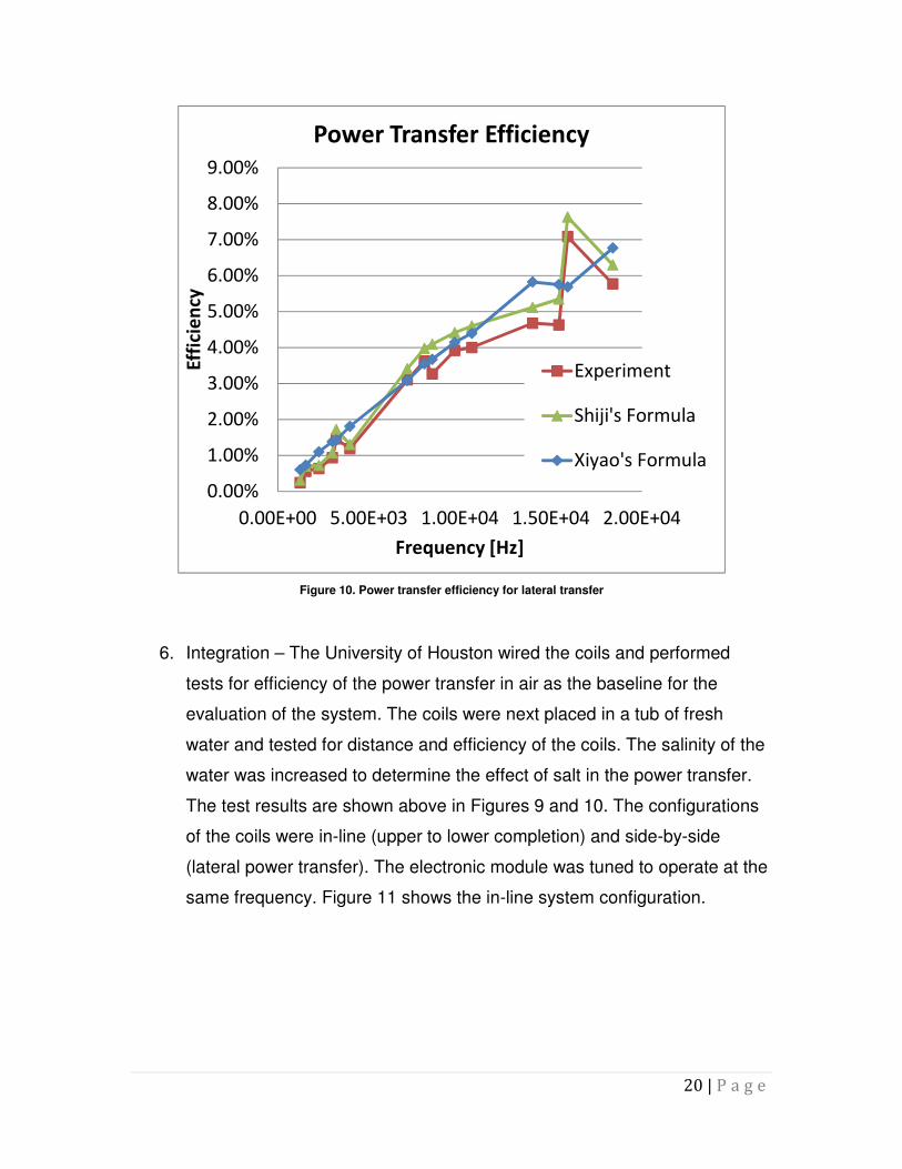
Figure 10. Power transfer efficiency for lateral transfer
6. Integration – The University of Houston wired the coils and performed
tests for efficiency of the power transfer in air as the baseline for the
evaluation of the system. The coils were next placed in a tub of fresh
water and tested for distance and efficiency of the coils. The salinity of the
water was increased to determine the effect of salt in the power transfer.
The test results are shown above in Figures 9 and 10. The configurations
of the coils were in-line (upper to lower completion) and side-by-side
(lateral power transfer). The electronic module was tuned to operate at the
same frequency. Figure 11 shows the in-line system configuration.
0.00%
1.00%
2.00%
3.00%
4.00%
5.00%
6.00%
7.00%
8.00%
9.00%
0.00E+00 5.00E+03 1.00E+04 1.50E+04 2.00E+04
Eff
icie
ncy
Frequency [Hz]
Power Transfer Efficiency
Experiment
Shiji's Formula
Xiyao's Formula

21 | P a g e
Figure 11 Configuration of the wireless power and communications for upper and lower completion integration
The test results indicate that the power transfer works properly and provides
the means to get power from the mainbore to the lateral or upper completion
to the lower completion.
The tests performed with the power transfer system showed that the system
could be improved and made more efficient. A new approach was developed
in which multiple cores are used in transmitter and receiver. The windings
were also changed to integrate all of the cores into one long core. This new
system will increase the magnetic field and provide a longer distance for the
transfer as well as provide more energy.
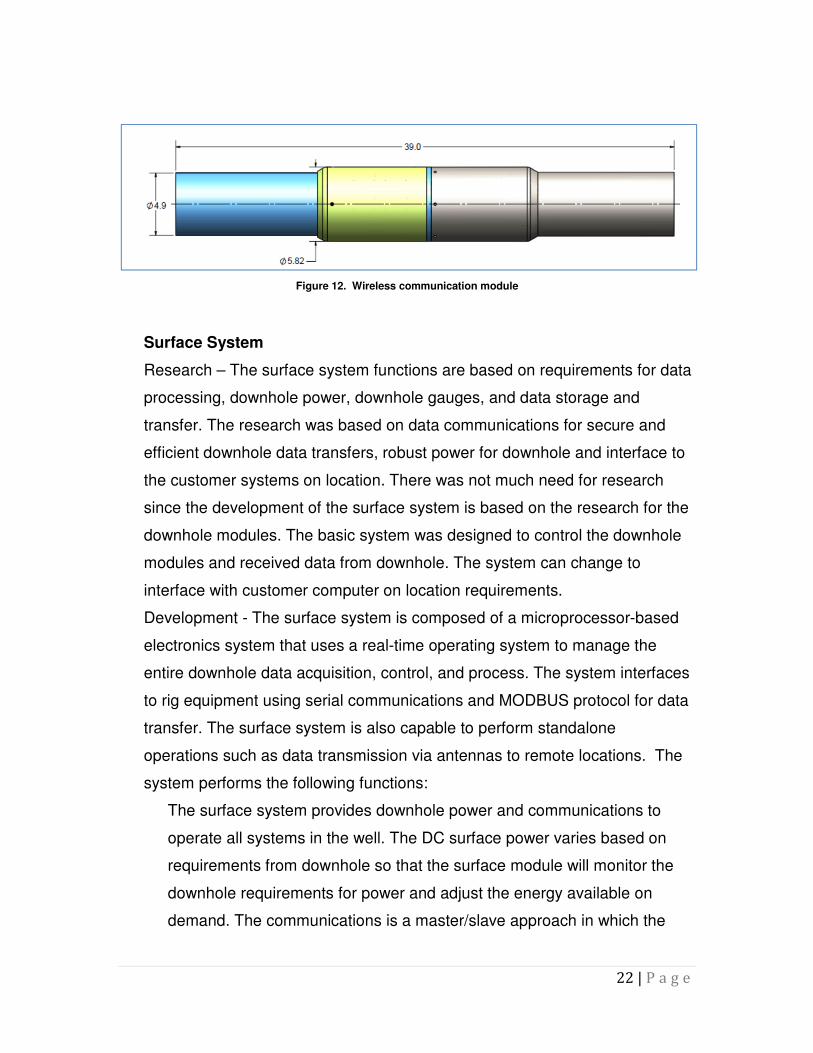
The wireless data transfer is based on the proven communications that is now
utilized in well fracturing monitoring applications. The system is based on
RFID transceivers that transmit and receive data. Each tool has an electronic
identification for data communications. Figure 12 shows the wireless
communications module.
22 | P a g e
Figure 12. Wireless communication module
Surface System
Research – The surface system functions are based on requirements for data
processing, downhole power, downhole gauges, and data storage and
transfer. The research was based on data communications for secure and
efficient downhole data transfers, robust power for downhole and interface to
the customer systems on location. There was not much need for research
since the development of the surface system is based on the research for the
downhole modules. The basic system was designed to control the downhole
modules and received data from downhole. The system can change to
interface with customer computer on location requirements.
Development - The surface system is composed of a microprocessor-based
electronics system that uses a real-time operating system to manage the
entire downhole data acquisition, control, and process. The system interfaces
to rig equipment using serial communications and MODBUS protocol for data
transfer. The surface system is also capable to perform standalone
operations such as data transmission via antennas to remote locations. The
system performs the following functions:
The surface system provides downhole power and communications to
operate all systems in the well. The DC surface power varies based on
requirements from downhole so that the surface module will monitor the
downhole requirements for power and adjust the energy available on
demand. The communications is a master/slave approach in which the
23 | P a g e
surface system starts the interface by asking a downhole gauge or flow
control system for data or status. It waits for the downhole module to reply.
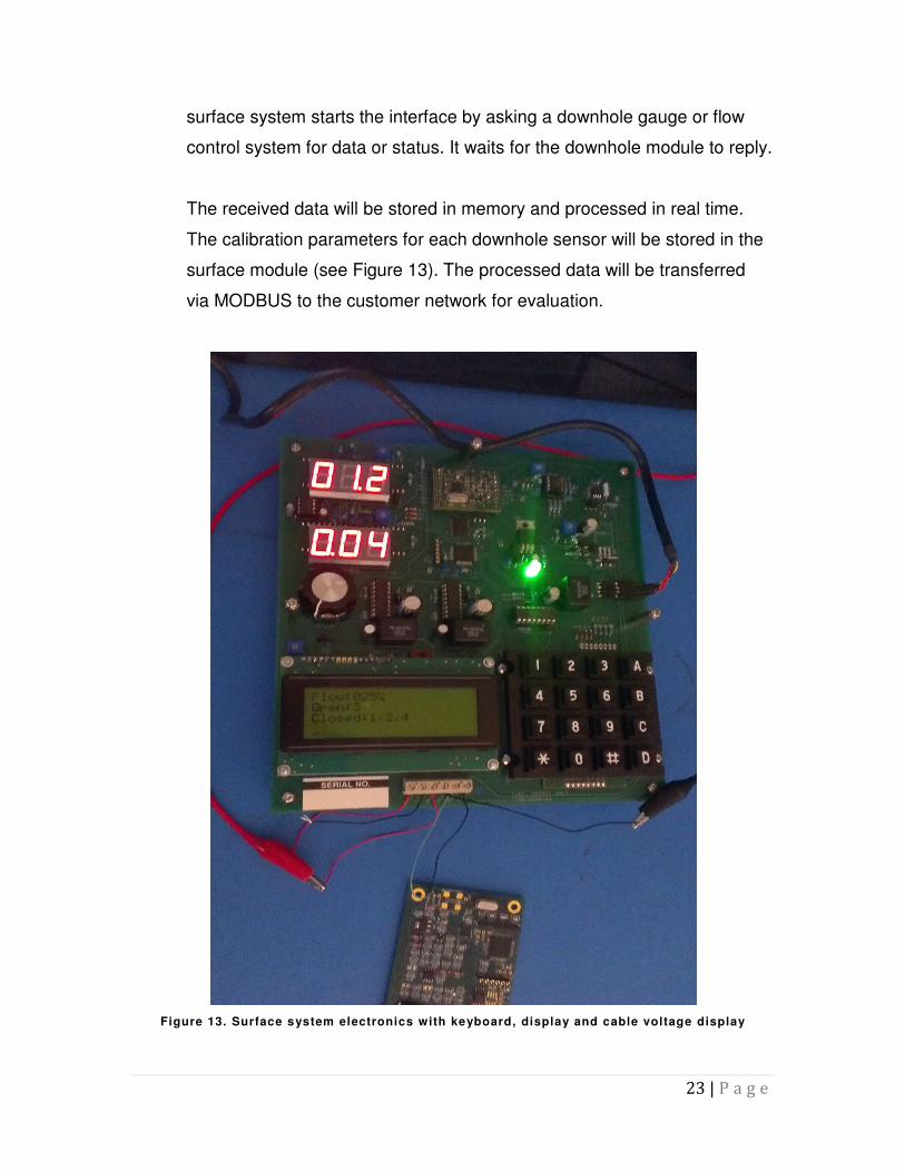
The received data will be stored in memory and processed in real time.
The calibration parameters for each downhole sensor will be stored in the
surface module (see Figure 13). The processed data will be transferred
via MODBUS to the customer network for evaluation.
Figure 13. Surface system electronics with keyboard, display and cable voltage display

24 | P a g e
The surface system has a display and keyboard that allows the operator to
see data being received from downhole in real time. It also is able to
provide manual commands to open or close flow from a flow control tool.
The modules for the surface system were integrated in the laboratory and
tested. The gauges and surface system were interfaced over 15,000 feet of
cable to ensure that the communications worked properly and that the
modules could exchange information between the surface and downhole. The
surface system was also tested for opening and closing the flow control tools.
The data from the gauges were stored in the local gauge memory during the
opening or closing of the sleeves. The data were transmitted to the surface
once the flow control command was completed. The surface system was also
tested with a PC to prove that the data could be transferred to a remote
location or the customer computers.
Figure 14. Flow Control - Surface Control Panel Block Diagram
CPU
Memory
LCD Displa
USB Interface
V/I Display
Cable Drive
User Input
SMP
To Flow Control Module(s)
120V/60Hz AC
PC Host

25 | P a g e
Commercial Job – Shell has indicated that it wants to install the Intelligent
System on a fracture stimulation in which four flow control systems with built-
in gauges will be deployed using a single electrical cable connecting the
surface system to the downhole tools. BP has also shown interest in the
technology and has requested a system for a through-tubing application in
which the gauges are built separate from the flow control tool. The BP system
is for wireless actuation applications requiring no cables in the well.
Documentation – The documentation will be developed during the entire
process of creating the new system. The documentation is composed of the
following:
Manufacturing drawings to build the gauges and flow control devices as
well as the power transfer units.
Calibration procedures for all surface and downhole modules to ensure
that the accuracy of the systems are within the requirements.
Environment tests for pressure and temperature to ensure that the system
will perform properly in the wellbore.
Deployment methodology to provide the installer with instructions on how
to deploy the entire system in the well.
System operation procedure to provide instructions for the operation of the
surface system and downhole tools.
Evaluation and repair of the system during manufacturing and calibration
Surface system data transfer protocol requirements and data transfer
techniques.
Experimental Methods
The experiments performed for the development of the Intelligent Production
System for Ultra-deepwater with Short Hop Wireless Power and Wireless Data
Transfer for Lateral Production Control and Optimization project were based on
multiple levels of testing from component level to circuit level in order to complete
26 | P a g e
integration testing and evaluation. All components were tested for proper
operation to determine potential for failure at elevated temperatures, and the
mechanical components were tested to ensure that they will maintain the proper
tolerance under temperature for sealing purposes.
The electronic components were oven tested for life expectance and for normal
operating temperature. Cycling of the components allowed the components to
age, thus providing an estimate of each component’s life. The Printed Circuit
Boards with all components were left in an oven at 250 degrees Fahrenheit over
1 year. The oven was cycled every 2 months to provide the aging of the
components. The parts performed well with no failures.
Long term tests for electromechanical devices such as motors were performed in
specially developed fixtures to provide the simulation of the operating
environment. As an example the flow control tool is expected to be operated
once a month in a well. The test performed in a laboratory oven was performed
at 125 degrees Celsius and operated the tool on average once every 30
seconds. The motor was actuated 120 times per hour, or 1,440 times per day.
The motor operated without a failure for three months in the oven, for a total
actuation of 130,000 times. The actuation module for the tool, which controls
motor actuation, was also deployed in the oven.
The evaluation of each mechanical component started by obtaining the data
sheet from the material supplier indicating its material property. Once the parts
were manufactured, they were checked for proper dimensions and tolerances.
The parts were assembled into a tool and pressure tested to 5,000 psi differential
to to assure that the tool had no leaks. The material chosen for this application
was 17-4 stainless. It was heat treated to strengthen the material to withstand a
higher downhole pressure. The test results were successful.
Once the electronic module was assembled in the mandrel, the complete system
was tested under temperature by placing a heat tape over it. The temperature

27 | P a g e
was monitored on the surface of the tape to ensure that the temperature was
correct for the given test. The sensors and motor operation were tested using the
heat tape to assure that the tolerances of the system and thermal coefficients of
expansion did not create a mismatch to the moving parts. The system worked
well at 250 degrees Fahrenheit.
Upon completion of the tests, the flow control tool with the embedded sensors
was tested in a pressure chamber to ensure that it would withstand the pressure.
Five pressure cycles at 30 minutes each were performed on the tool. The tool
passed all the tests performed.
The sensors were oven calibrated with the electronic data acquisition board to
ensure that all errors were accounted for, and the sensors were then calibrated
for proper and accurate pressure data in the well. Each sensor and board were
matched and installed in the tool as a pair.
The surface system was attached to the cable simulator and performed its
functions as the flow control tool and pressure sensors data were monitoring. A
power meter provided an estimate of the power transfer capability of the tool at
multiple distances.
A total of four flow control systems were attached to a single cable system to
ensure that the surface system could access different tools in the well with a
single cable.
All the flow parts located in the flow control tools were carbon-coated to minimize
flow erosion. A flow loop test will be performed in early March and results will be
included in this document.
The test charts for the Intelligent System are located below.
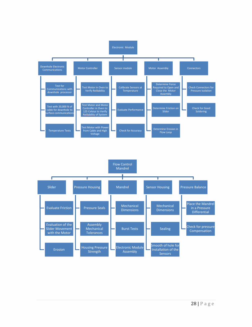
28 | P a g e
Electronic Module
Downhole Electronic
Communications
Test for
Communications with downhole processor
Test with 20,000 ft of
cable for downhole to surface communications
Temperature Tests
Motor Controller
Test Motor in Oven to
Verify Reiliability
Test Motor and Motor
Controller in Oven to 125 Celsius to Verify Reiliability of System
Test Motor with Power
from Cable and High Voltage
Sensor module
Calibrate Sensors at
Temperature
Evaluate Performance
Check for Accuracy
Motor Assembly
Determine Force
Required to Open and Close the Motor
Assembly
Determine Friction on
Slider
Determine Erosion in
Flow Loop
Connectors
Check Connectors for
Pressure Isolation
Check for Good
Soldering
Flow Control Mandrel
Slider
Evaluate Friction
Evaluation of the Slider Movement with the Motor
Erosion
Pressure Housing
Pressure Seals
Assembly Mechanical Tolerances
Housing Pressure Strength
Mandrel
Mechanical Dimensions
Burst Tests
Electronic Module Assembly
Sensor Housing
Mechanical Dimensions
Sealing
Smooth of hole for Installation of the
Sensors
Pressure Balance
Place the Mandrel in a Pressure Differential
Check for pressure Compensation
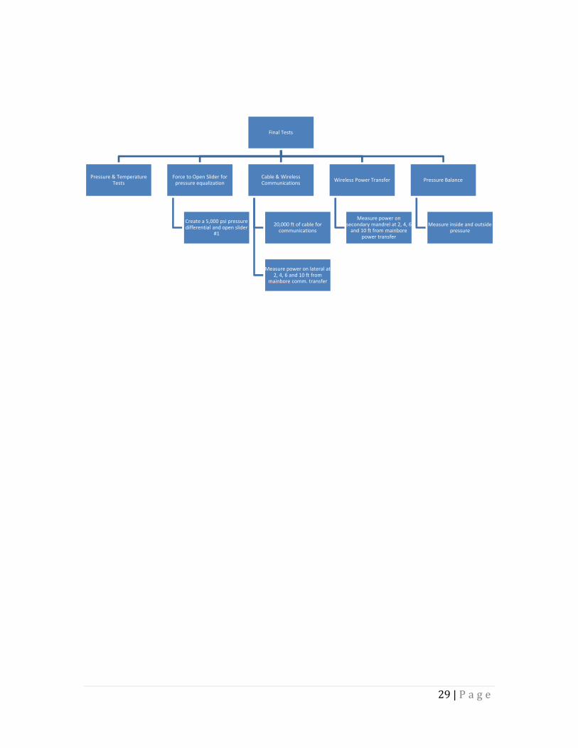
29 | P a g e
Final Tests
Pressure & Temperature Tests
Force to Open Slider for pressure equalization
Create a 5,000 psi pressure differential and open slider
#1
Cable & Wireless Communications
20,000 ft of cable for communications
Measure power on lateral at 2, 4, 6 and 10 ft from
mainbore comm. transfer
Wireless Power Transfer
Measure power on secondary mandrel at 2, 4, 6
and 10 ft from mainborepower transfer
Pressure Balance
Measure inside and outside pressure

30 | P a g e
Results and Discussion
The Intelligent Production System for Ultra-deepwater with Short Hop Wireless
Power and Wireless Data Transfer for Lateral Production Control and
Optimization has been developed successfully. The system provides a new way
to control and monitor production by integrating sensors into the flow control
device and having a system operating at ultra-low power in which the opening
and closing of the flow control requires 1.2 Watts of power, compared to 50
Watts of power currently required for inner sleeve-based electric flow control
systems. The new system also has four flow control ports that provide production
control flexibility by being able to choke the flow with minimum erosion. The flow
control provides a larger inside diameter and smaller outside diameter than
normal, allowing for higher flow rates through the tool, as well as system
installation in smaller diameter casing, which may save the operator a significant
amount of money.
The project attempted and succeeded in addressing a number of issues such as
following:
1. Reduction of the number of feed-through connectors in the wellhead;
2. Utilization of a single electric line in the well for flow control and sensors;
3. Integration of sensors with flow control tools;
4. Deployment capability in laterals of sensors and flow control tools;
5. Power deployment in the laterals;
6. Digital wireless communications in the laterals;
7. Power and communications transfer from the upper completion to the
lower completion wirelessly;
8. Battery operated flow control tools;
9. Pressure, temperature, flow and fluid identification sensors available for
permanent deployment in the well;

31 | P a g e
10. Through tubing deployment of sensors and flow control tools for existing
wells;
11. Increase in reliability for the downhole systems by having all sensors built
into the flow control tool.
12. Potential deployment of the flow control tool closer to the sand face in the
lower completion.
The utilization of a new low power, high reliability, and high temperature motor
technology for the actuation of the flow control tools has changed the way flow
control tools are designed and operated. The low power allows the system to
work for an extended period of time using batteries.
The new technologies implemented in this unique system can be applied to other
applications and other tools.
Impact to Producers
The Intelligent Production System for Ultra-deepwater with Short Hop Wireless
Power and Wireless Data Transfer for Lateral Production Control and
Optimization has been shown to personnel from two operating companies. Both
operators, Shell and BP Alaska, reacted positively to the development of the
system. Shell has purchased four systems with modifications for fracturing
applications. BP Alaska has also purchased a system but requested that it be of
a smaller outside diameter to be able to be deployed through 4.5-inch tubing.
Other products will be adapted based on the technologies and products
developed by this project, such as flow control gas lift valves, buttonhole
circulating valves, and smart packers with built-in sensors.
The new system will have a significant impact on production, safety, and the
environment to customers. The impact to the producers includes the following
scenarios:
32 | P a g e
a) Increasing the production of oil and gas resources by being able to optimize
hydrocarbon production from laterals, by deploying control and monitoring
hardware in the laterals, which can be controlled from a remote location at the
surface.
b) Increasing the production of oil and gas resources by being able to optimize
production from wells by remotely controlling the flow from downhole to the
surface and the capability to remotely monitor production parameters.
c) Increase hydrocarbon production by being able to deploy the sensors and
flow control systems at the sand face instead of the bottom of the upper
completion.
d) Reducing the costs to develop and produce such resources by being able to
deploy a control system in the wellbore that will transfer power and
communications in the laterals and in the lower completion from the upper
completion wirelessly, to optimize production and reduce the interventions in
the well.
e) Increasing the efficiency of exploitation of such resources by controlling the
production in the laterals so that laterals can be divided into multiple
producing zones, allowing for production from the toe (end) of the well instead
of mostly from the heel (entrance) of the lateral, as is common.
f) The ability to monitor water production will allow the operator to precisely
know the location of the water production that can then be remotely shut-in,
reducing water processing costs at the surface and maintaining hydrocarbon
production for a longer period of time.
g) Increasing production efficiency and ultimate recovery of such resources by
controlling the encroachment of water in the production stream as well as
slowing the movement of water into the producing zone. The production of
water can quickly replace the production of hydrocarbons inside the
production tubing, decreasing the production efficiency. The movement of
water into a producing zone will otherwise ultimately reduce the amount of
hydrocarbons that can be produced from that zone.

33 | P a g e
h) Improving safety and environmental performance, by minimizing
environmental impacts associated with ultra-deepwater exploration and
production by reducing the number of wells drilled and minimizing the number
of interventions in wells. The reduction in the number of wells drilled will occur
because multilateral production will become much more efficient and well
count can be optimized, therefore protecting the environment. The reduction
in the number of interventions in wells, as well as fewer wells, will reduce the
chance for accidents that can affect the safety at the well site because of a
reduction in human activity.
Technology Transfer Efforts
Tubel LLC worked with RPSEA throughout the project to implement an effective
Technology Transfer program. Technology Transfer activities consisted of both
project and program level activities. Tubel participated in RPSEA sponsored
activities, including Technical Advisory Committee (TAC) meetings, conferences,
and workshops.
The technology transfer provided by Tubel LLC included the tasks outlined
below:
1. Presented at the Ultra-deepwater Annual Conference on July 26, 2011.
2. Presented at the Ultra-deepwater Annual Conference on September 20,
2012.
3. Presented the technology and project status at the RPSEA Drilling,
Completion and Intervention TAC Meetings on May 10, 2011, January 26,
2012, May 24, 2012, and January 24, 2013.
4. Submitted all presentation materials to RPSEA for posting for all of the above
activities.

34 | P a g e
Conclusions
The “Intelligent Production System for Ultra-deepwater with Short Hop Wireless
Power and Wireless Data Transfer for Lateral Production Control and
Optimization” project has provided Tubel LLC with the ability to develop quite a
few new technologies embedded into a single system for deployment in
deepwater applications. The system is composed of the following new
technologies:
1. Wireless Power Transfer – This module provides the ability to transfer
electricity between 2 points in the wellbore. The applications in a
standalone mode include energy transfer between main bore and lateral
as well as energy transfer between upper completion and lower
completion modules.
2. Wireless Communications Transfer – This module has the ability to short
hop two-way communications between downhole modules. The
applications include communications between the main bore and laterals,
communications between a permanently deployed module and a receiver
module that is deployed in a well via slick line or electric line to retrieve the
data, communications between upper and lower completion modules, and
communications to and from below and above a seal or barrier in the well.
3. Low Power High Stability Sensors – Pressure sensors using sapphire
windows have been proven to be quite stable under wellbore conditions
and also provide very simple calibration process to maintain its accuracy.
These low cost systems can be deployed in multiple downhole
applications to instrument most completion tools.
4. Low Power Flow Control System – This new system can revolutionize the
completions sector of the business. The new system offers multiple
features for existing and future applications such as the following:
a. Multiple systems can operate in a single downhole cable due to the
low power and small voltage losses on the cable.

35 | P a g e
b. Elimination of the single inner sleeve used to control the flow in the
well.
c. Development of small sliders that can be controlled individually
from the surface to open and close multiple sections, choke the
flow for reservoir/production management of flow, and/or slow the
encroachment of water into the flow stream.
d. The ultra-low power necessary for the operation of the flow control
will allow for the development of other devices that can be used to
control the flow in the well such as gas lift valves, circulating valves,
and others.
e. The low power flow control system reduces the number of feed-
through connectors at the wellhead, increasing safety and
reliability, and decreasing system costs.
f. A new line of battery operated flow control tools can be developed
which will not require downhole cables for operation. These new
systems can be deployed in existing wells, creating a new product
line for operations in wells that may shut-in or required control from
the surface.
5. Integration of Sensor Technology in Completion Tools – Multiple sensors
can now be deployed as part of the flow control system. The sensors will
improve the reliability of the system by eliminating additional splices on the
downhole cable and reducing the electronics components required for
data acquisition and data communications. The integrated system can
reduce operating costs as well: for example, other tools such as packers
can be integrated with downhole sensors to improve performance.
6. Integrated Surface System – The new surface system provides an
integrated command, control, and communications module that
commands the systems downhole to acquire and transmit data to the
surface as well as to command the flow control modules to open and
close. It processes the data and interfaces to other systems at the well
site.

36 | P a g e
The Intelligent Production System for Ultra-deepwater with Short Hop Wireless
Power and Wireless Data Transfer for Lateral Production Control and
Optimization has created new technologies as described above. Furthermore, it
has allowed new product lines to be developed for deployment in wells for better
flow control and production monitoring, improved wellbore and production safety,
and control of laterals.
Recommendations
There are quite a few recommendations for the improvement of the system. As
the technologies are introduced in the field, more applications for the system will
be created and more products will be developed to address other requirements,
both in completion and drilling applications.
Some of the recommendations for improvement and leverage the technologies
developed are:
1. Utilize the sensor integration technology to comply with new government
regulations that will require sensors to monitor devices that seal, block, or
control production in a well.
2. Integration of multiple completion tools, such as packers and flow control
modules and sensor technology, into a single package.
3. Expand the use of battery based technology for flow control including for
well cementing applications.
4. Increase the operating temperature to between 175 and 200 Celsius.
5. Utilize the wireless power transfer to bypass downhole tools, such as
packers, and eliminate costly feed-through connectors.
The utilization of downhole power generators may also provide more flexibility for
the flow control and sensor technologies downhole by allowing the wellbore to
become a network of sensors and a system that can be deployed anywhere in a
well. Eventually, the system may be capable of connecting to and integrating with
automated optimization software that can fully control each segment or node of

37 | P a g e
each lateral and the main bore of a well and self-adjust to maximize a well’s
value.