Embed Size (px)
Citation preview
Approved for public release; distribution is unlimited.
Final Technical Report
Environmentally Acceptable Medium Caliber Ammunition Percussion Primers
SERDP Project ID WP-1308
Prepared by
Michael Ellis U.S. Army RDECOM-ARDEC
AMSRD-AAR-AEM-J Picatinny Arsenal, NJ 07806-5000
31 October 2007
This research was supported in part by the U.S. Department of Defense, through the Strategic
Environmental Research and Development Program (SERDP)

Approved for public release; distribution is unlimited.

This report was prepared under contract to the Department of Defense Strategic Environmental Research and Development Program (SERDP). The publication of this report does not indicate endorsement by the Department of Defense, nor should the contents be construed as reflecting the official policy or position of the Department of Defense. Reference herein to any specific commercial product, process, or service by trade name, trademark, manufacturer, or otherwise, does not necessarily constitute or imply its endorsement, recommendation, or favoring by the Department of Defense.
i Approved for public release; distribution is unlimited.
Table of Contents
Page Table of Contents i List of Figures and Tables ii Acronym List iv Acknowledgements 1 1.0 Executive Summary 2 2.0 Background and Objective 3 3.0 Materials and Methods, Results and Accomplishments 5 3.1 MIC Morphology 5 3.1.1 Particle Sizes, Particle Size Distribution and Oxide Layer 5
Thickness 3.1.2 Reaction Mechanisms 8
3.1.3 Composite Uniformity (Material Mixing) 14 3.2 Laboratory Ignition Tests and MIC Formulation Development 17 3.3 Live Fire Ballistic Testing 28
4.0 Summary and Conclusions 32 Appendices A. References B. Industry Standard Percussion Primer Drop Fixture C. LANL Individual Shot Data D. 25mm M793 TP-T Ballistic Test Results E. Primer Accidental Ignition Incident
ii Approved for public release; distribution is unlimited.
List of Figures and Tables Page
Figures Figure 1 Cross sectional sketch of the M115 percussion primer 3 Figure 2 Conventional medium cannon caliber percussion primed fixed 4
ammunition cartridge Figure 3 TEM showing difficulty in measuring particle sizes of nano 5
aluminum Figure 4 Comparison of Size Distributions Obtained From a SAXS 6
Measurement and TEM Images Figure 5 Instrumented burn tube test setup 8 Figure 6 Sequence of still frame images captured during open tube testing 9
of MIC
Figure 7 High speed sequential images of burning MIC in a glass tube 10 Figure 8 Radiant propagation setup 11 Figure 9a Constant volume reaction chamber includes pressure and light 12
intensity measurements Figure 9b Constant volume reaction chamber includes pressure and light 12
intensity measurements Figure 10 Pressure variations as a function of time indicate ignition time, 13
peak pressure and pressurization rate. Figure 11 SEM image of aluminum/molybdenum trioxide 14 Figure 12 SEM image of aluminum/bismuth trioxide 15 Figure 13a LANL primer firing pressure cell schematic 17 Figure 13b LANL primer firing pressure cell photograph 17 Figure 13c LANL primer firing pressure cell and firing mechanism 18
computer model Figure 14a ARDEC primer firing closed bomb 19

iii Approved for public release; distribution is unlimited.
Figure 14b ARDEC primer drop test apparatus 19 Figure 14c ARDEC Primer Laboratory Sensitivity Test Apparatus 19 Figure 15 LANL primer press assembly for preparing experimental 21
MIC No. 41 primers Figure 16 MIC Primer Laboratory P-t performance of Final Primer Build 26 Figure 17 M793 Test Cartridge with Drilled Cartridge Case for Chamber 28
Pressure Measurement
Figure 18 25mm Mann Barrel Test Setup at ARDEC Indoor Test Range 29
Tables Table 1 Comparison of Aluminum Particle Sizes Using Different 7
Measurement Techniques Table 2 LANL Laboratory Percussion Primer Performance 22 Table 3 ARDEC Laboratory Percussion Primer Performance 24 Table 4 25mm M793 TP-T Test Cartridge Components 28

iv Approved for public release; distribution is unlimited.
Acronym List
ADP Ammonium Dihydrogen Phosphate Al Aluminum ARDEC Armament Research Development and Engineering Center BET S. Brunauer, P.H. Emmett and E. Teller Bi2O3 Bismuth Trioxide BTATz 3,6-bis(1H-1,2,3,4-tetrazol-5-amino)-s-tetrazine or Bis-aminotetrazolyl-tetrazine CAD Cartridge Actuated Device CFR Code of Federal Regulations cm Centimeter cm3 Cubic centimeter CR Calcium Resinate CuO Cupric Oxide DAATOx Diamino-azo-tetrazine oxidized to “x” dP/dt Change in pressure per change in time EC Ethyl Cellulose EPA Environmental Protection Agency ESD Electrostatic Discharge Fe2O3 Iron trioxide g Gram IMP Innovative Materials and Processes IPA Isopropyl alcohol or isopropanol KCl Potassium Chloride LANL Los Alamos National Laboratory lbf Pounds force mg Milligram MIC Metastable Intermolecular Composites or as Metastable Interstitial Composites mm Millimeter MNC Metastable Nanoenergetic Composites MoO3 Molybdenum Trioxide MPa MegaPascal msec Millisecond m/s Meters per Second m/sec Meters per Second

v Approved for public release; distribution is unlimited.
nano Nanometer NC Nitrocellulose Nd:Yag Neodymium-doped yttrium aluminum garnet nm Nanometer NSWC-IH Naval Surface Warfare Center – Indian Head oz Ounce PAD Propellant Actuated Device PETN Pentaerythritol tetranitrate psi Pounds per Square Inch PVDF Polyvinylidene Difluoride RDX Cyclotrimethylenetrinitramine SANS Small Angle Neutron Scattering SAS Small Angle Scattering SAXS Small Angle X-ray Scattering SDSMT South Dakota School of Mines and Technology SERDP Strategic Environmental Research and Development Program SEM Scanning Electron Microscopy TEM Transmission Electron Microscopy TGA Thermo Gravimetric Analysis TMD Theoretical Maximum Density TP-T Target Practice with Trace VOC Volatile Organic Compound WO3 Tungsten trioxide µm Micrometer µsec Microsecond
1 Approved for public release; distribution is unlimited.
Acknowledgements This work was supported by the Strategic Environmental Research and Development Program (SERDP). The author wishes to thank Charles Pellerin, SERDP Weapons Systems and Platforms Program Manager, and HydroGeoLogic, Inc. for their support during execution of the project. The author also wishes to acknowledge the technical expertise provided by Dr. Rao Yalamanchili, Roman Fedyna, John Hirlinger, Chris Csernica and Alyssa Wiley of ARDEC; Thomas Doris of Applied Ordnance Technologies (formerly from ARDEC); Magdy Bichay and Todd Allen of the NSWC-IH; Dr. Steven Son of Purdue University (formerly from LANL); James Busse of LANL; and Drs. Jan Puszynski and Jacek Swiatkiewicz of IMP/SDSMT.

2 Approved for public release; distribution is unlimited.
1.0 Executive Summary Percussion primers are used to ignite fixed ammunition propellant charges with a very high functional reliability. In order to achieve this high degree of reliability, extremely sensitive primary explosive compositions are selected as the initiating materials. Percussion primers, including those used in medium caliber ammunition, typically contain lead styphnate and antimony sulfide along with other constituents. Although highly effective, these heavy metal compounds have been identified under 40 CFR 401.15 as toxic pollutants and should be replaced or eliminated. Furthermore, current percussion primer compositions also contain barium nitrate. Although not negatively categorized by the EPA itself, barium compounds are generally regarded as toxic and likewise should be replaced or eliminated. Commencing in April 2002, this project identified, characterized, tested and evaluated environmentally benign candidate materials as potential replacements for the hazardous composition currently used in medium caliber ammunition percussion primers. This effort was structured to enhance a new class of non-toxic energetic materials called Metastable Intermolecular Composites (MIC)1 originally developed by LANL and refined for use in small caliber ammunition percussion primers under the SERDP sponsored project “Elimination of Toxic and VOC Constituents from Small Caliber Ammunition” (Reference 1). MIC offers a non-toxic alternative to conventional military primers with constituents of a nano-sized metal fuel mixed with a sub-micron-sized metal oxide. Metal/metal oxide compounds have been used for years as thermite compounds which are characterized by extremely high energy output when initiated, but are generally considered too slow to initiate for primer purposes at the standard particle sizes. In MIC, the intimate mixture of these constituents at the submicron level provides a metastable system which can react orders of magnitude faster than conventional thermite compositions. By manipulating the size and intimacy of the components, sensitivity and explosive output can be tailored for each application. The M115 primer primarily used in 25mm ammunition was the performance baseline. Primer sensitivity, ignitability, stability, consistency, compatibility, and energy release performance was used to screen potential candidates in a laboratory environment. Selected materials were then loaded into 25mm TP-T M793 cartridges and functionally tested for interior ballistic conformance. A successful demonstration of MIC percussion primers in medium caliber ammunition was performed in April 2007 to complete the funded SERDP program.
Provisional patent application number 60/917412 for the final MIC based primer with booster ignition system was filed with the US Patent and Trademark Office on 11 May 2007.
1 Throughout various documents and sources, MIC is synonymous with MNC.

3 Approved for public release; distribution is unlimited.
2.0 Background and Objective
The M115 percussion primer used in the medium cannon caliber 25mm ammunition family contains the lead styphnate based FA956 composition2 which is a typical formulation of conventional military ammunition percussion primers. The nominal charge weight is 233mg. Figure 1 is a schematic of the physical construction of the M115 primer. Anvil (bipodal) Foil seal FA956 primer composition Cup
Figure 1 Cross sectional sketch of the M115 percussion primer
The anvil can be either bipodal or tripodal and is typically made of brass. When a percussion primed cartridge is chambered in a weapon, the weapon firing pin strikes the face of the primer cup and the primer mix is compressed against the anvil which is constrained from forward movement in the cartridge case pocket. Rapid adiabatic compression ignites the primer mix. The foil seal is typically a nitrocellulose lacquered paper. It is often required during the primer mix consolidation process of primer assembly at the manufacturing facility to prevent mix material from adhering to the punch and presenting a potential safety hazard during subsequent operations. The primer composition is classified as a primary high explosive. It provides the rapid release of extremely hot, high velocity particles into either a booster pellet or directly into the propellant bed of a munition product to initiate its function. The cup, like the anvil, is typically made of brass. The cup is the housing that contains the primer assembly. Its face is struck with the weapon firing pin to initiate the functioning of the primer. In conventional percussion primed ammunition, the primer is located in the head of the cartridge case. In many applications, a booster is positioned between the primer and the main propellant charge. The booster is a high explosive element sufficiently sensitive so as to be actuated by the primer and powerful enough to ignite the main propellant charge. In this particular application, the booster pellet is primarily comprised of boron potassium nitrate. See Figure 2.
2 Because of technical data export control restrictions, the complete formulation of the M115 percussion primer can not be presented in this report.
4 Approved for public release; distribution is unlimited.
Primer Booster pellet
Figure 2 Conventional medium cannon caliber percussion primed fixed ammunition cartridge
Percussion primed medium caliber ammunition in the current US military consists of 25mm, 30mm, and 40mm fixed cartridges. Millions of rounds of medium caliber ammunition are fired each year in training and combat. Each round fired disburses a few milligrams of lead, antimony, and barium compounds into the atmosphere. In total, hundreds of pounds of these toxins pollute the environment each year. The objective of this project is to eliminate these pollutants by replacing the current percussion primer composition with an environmental benign alternate. Approximately 15 years ago, scientists at LANL developed a unique energetic composite that consisted of two reactive components, a fuel and an oxidizer, separated by a buffer. Reaction occurred exothermically when the buffer was disturbed by some external stress. Rate of reaction could be tailored by the size of the individual components and proximity to each other. Nanometer sizes were used to generate reaction speeds approaching those of conventional explosives. This new energetic composite was called MIC (metastable interstitial composite) and one combination consisted of nano aluminum (Al) and cupric oxide (CuO). US patent 5,266,132 was assigned. Subsequently, patent 5,717,159 was assigned to scientists at LANL and the US Navy when they refined the original MIC for application to ammunition percussion primers. This MIC consisted of nano aluminum and molybdenum trioxide (MoO3). Shortly thereafter, the US Army and US Navy proposed to SERDP the application of the latter invention to small caliber percussion primed ammunition and medium cannon caliber electric primed ammunition respectively. Further refinement of the patented MIC was made by adding gas generate(s) to meet action time (time lapse from primer strike to projectile exit from the weapon) and to make it suitable for use in the extreme temperature environment required of military ammunition. Successful application of the basic MIC material with a gas generate additive by the US Army in the No. 41 percussion primer used in 5.56mm small caliber ammunition (Reference 1) prompted the US Army to pursue the technology in medium cannon caliber percussion primed ammunition again with the sponsorship of SERDP. This report documents this medium caliber ammunition effort.

5 Approved for public release; distribution is unlimited.
3.0 Materials and Methods, Results and Accomplishments
3.1 MIC Morphology
Little was known about the intrinsic characteristics of MIC materials when efforts began to adopt the technology to military primer applications. As such, a thorough examination of particle sizes, particle size distributions, oxide layer thickness, reaction mechanism, reaction rate and composite uniformity was performed to attempt to fully characterize the behavior of MIC.
3.1.1 Particle Sizes, Particle Size Distribution and Oxide Layer Thickness
Because of their expertise in the areas of research chemistry, the High Explosives Science and Technology division at LANL was tasked to investigate the basic characteristics of MIC. Using specialized techniques such as small angle scattering (SAS) employing x-rays (SAXS) and neutrons (SANS) along with transmission electron microscopy (TEM), scanning electron microscopy (SEM), BET (S. Brunauer, P.H. Emmett and E. Teller) gas absorption and thermo gravimetric analysis (TGA), LANL characterized the structure of MIC. More important than the actual measurements of the samples themselves was the endorsement of the technique for use in these applications. Limitations in sample sizing (hundreds of particles) in analyses using microscopy prompted the use of SAS (quantities on the order of magnitude of 1018) resulting in a much higher statistically significant sample. Moreover, microscopy introduces errors in measurements because of the difficulties in determining particle sizes due to agglomerates and a halo effect from electron diffraction (see Figure 3).
Figure 3
TEM showing difficulty in measuring particle sizes of nano aluminum

6 Approved for public release; distribution is unlimited.
Figure 4 is a representative plot comparing particle size distribution obtained from SAXS and TEM. Although the distributions of the populations are similar, the means differ by nearly 10nm when measured with the two different techniques.
Figure 4 Comparison of Size Distributions Obtained From a SAXS Measurement and TEM Images
More information and detailed descriptions on nano particle measurement techniques can be found in references 2 and 3. References 2 and 3 also include specific nano aluminum size analyses comparing various measurement techniques. Table 1 is a summary of these results. The particle sizes measured by BET are actually calculated from the BET surface area measurements and the density of the material measured by helium pycnometry. In order to perform the calculations, the material is assumed to be spherical and monosized, which it is not. Therefore particle size indirectly measured by BET is not truly accurate. Nonetheless, it agrees reasonably well with the SAS measurements correlating surface area and density as well. SAS measurements of particle diameter are consistently smaller then BET. Even though SAS techniques distinguish between aggregates and primary particles and can elucidate fine structural details; something BET and TGA cannot accomplish, BET probes on a smaller length scale then SAS and can account for small surface defects missed by SAS. BET can not, however, account for aggregation.
7 Approved for public release; distribution is unlimited.
Table 1 Comparison of Aluminum Particle Sizes Using Different Measurement Techniques
Average Particle Diameter (nm) Oxide Layer
Thickness (nm) Aluminum
Sample Source
SAS1 SAS2 BET TEM TGA SAS 13100 LANL 38 ± 5 49 ± 2 46 1.6 2.4 ± 0.6 31500 LANL 28 ± 3 33 ± 3 30 40 ± 8 1.6 3.1 ± 0.4 RF-B LANL 32 ± 6 42 ± 3 46 3.0 3.0 ± 0.6
40 Technanogy 30 ± 3 46 ± 4 44 2.0 2.5 ± 0.7 44 Nanotech 32 ± 4 51 ± 5 44 4.3 5.0 ± 1.0 80 Nanotech 44 ± 4 71 ± 7 70 4.4 4.0 ± 1.0
1 Average value of SANS and SAXS results calculated from the average core radii and oxide layer thicknesses
2 Mean particle size calculated from SAS determined particle density and surface area
The combination of techniques is necessary and enables a thorough characterization of nano particles which can be used to certify and accept nano particle systems based on the quantification of their microscopic structure.

8 Approved for public release; distribution is unlimited.
3.1.2 Reaction Mechanisms
Because of their expertise in the related field, the High Explosives Science and Technology division at LANL was again tasked to perform MIC ignition and reaction propagation studies. Using various laboratory test and measurement techniques, LANL determined the physical mechanism that controls the reactive wave propagation of MIC combustion. Figure 5 is a photograph of the instrumented burn tube developed to obtain experimental burn rate data (Reference 4).
Figure 5
Instrumented burn tube test setup An acrylic tube, filled with MIC material, is positioned along the center horizontal axis of the acrylic block. The transparency of the acrylic allows for high speed imaging of the event. Fiber-optic photo-detectors and piezo-electric pressure transducers instrument the block to measure combustion velocity and pressure. An electric match or exploding bridgewire ignites the sample for one end of the acrylic tube. A series of flame propagation tests were performed on select samples of MIC with varying nominal aluminum particle size, oxidizer and mixture density (References 4). For loose fill3 Al/ MoO3, independent burn tube tests produced an average pressure in the 2500 psi range with propagation velocities in the 950 m/s range. For loose fill Al/Bi2O3, the pressure and velocity were 7750 psi and 646 m/s respectively. Reaction speed was found to be dependent on the material packing density and particle size of the aluminum fuel with no apparent speed advantage below a nominal 80nm diameter. Reaction speed decreased dramatically for Al/ MoO3 to 580 m/s while burn consistency improved and pressure increased to 6595psi by increasing the bulk density of the powder. These performance changes were not 3 Loose fill is defined as a percentage of the TMD. Typically, this percentage varied from 5% to 17% indicating no compaction of the material; hence “loose fill”. The higher TMD percentages (i.e. bulk densities) were achieved by vibrating the acrylic tube as the MIC material was poured in.

9 Approved for public release; distribution is unlimited.
present with Al/Bi2O3 as velocity only decreased to 560 m/s while pressure also decreased to 5700 psi. It’s possible that conductive propagation is more apparent with higher density Al/Bi2O3 then Al/ MoO3. Since percussion primers consist of consolidated energetic material, the higher density speeds are likely more indicative of the final product. Reaction speeds in excess of 500 m/s were measured for all candidate materials and should be suitable for priming compositions. Results of the low density propagation study show a sharp rise in the pressure-time trace which is consistent with convective burning. However, the irregular flame front of some of the higher density tube tests reveals that conduction transport has not become dominant likely because the densities still remain relatively low. The planar flame front of consolidated pellet burns is indicative of conduction burning. It is suspected that the significant increase in density inhibits the ability of heat transfer by convection, but the increased contact between particles supports conduction. Supplemental tests were performed with loose pack MIC ignited in a vacuum. Propagation rate increased while pressure decreased indicating yet a possible contribution from radiant transport. Additional speculation of radiant transport contribution was hypothesized from the intense light output observed during the burn tube trials (see Figure 6).
Figure 6 Sequence of still frame images captured during open tube testing of MIC.
In figure 6, images are roughly 20 microseconds (µsec) apart. Note [a] in image (b) of figure 6 indicates the first sensor location as shown in figure 5 (i.e. the relative location of the fiber-optic photo-detector and piezo-electric pressure transducer along the acrylic tube). Subsequent stations are likewise visible in the other images (c) through (f) (i.e. the five remaining photo-detector/transducer ports along the tube).
According to reference 5, reactions that are dominated by conduction are typically characterized by a relatively slow but steady propagation rate when burned at constant pressure and usually exhibit a planar reaction front. In a convective dominant reaction, the reaction front will propagate much faster with noticeable acceleration. When confined, convectively dominant

10 Approved for public release; distribution is unlimited.
reactions will demonstrate pressure build up that could ultimately result in detonation. This would explain the behavior observed in the burn tube tests with Al/Bi2O3. During burn tube tests similar to those described above, but smaller and without instrumentation (see Figure 7), highly luminescent plumes are ejected from the tube ends.
Figure 7 High speed sequential images of burning MIC in a glass tube
The burn tube depicted in figure 7 is 6cm long and 3.8mm in diameter. The photo sequences are 30µsec apart. These plumes are likely composed of gas and high temperature particulates. The expansion of the exit plume indicates pressurization of the tube. Gaseous transport is clearly present and illustrated in the plumes on the tube ends. Plumes of particulates are suggestive of significant pressurization generated by the reaction such that convection again has been demonstrated to be the dominant process since conduction does not involve the bulk motion of a fluid, but rather heat transfer by random atomic or molecular activity. The images in figure 7 indicate that the bulk motion of a fluid may be integral in the reaction, suggesting convection as a dominant mechanism controlling the reaction. Furthermore, the observed transient behavior is indicative of convective influences because convective burning consists of the reaction spreading through the bed with burning continuing behind the ignition front. This burning behind the
11 Approved for public release; distribution is unlimited.
ignition front continues to contribute to the pressure field within the tube which serves to further accelerate the ignition front. In normal deflagration (conductive driven burning), the material is consumed in a thin region and, if the sample is unconfined, the pressure equilibrates with the surrounding environment.
To evaluate the effect of radiant transport, another series of tests were performed. Figure
8 is a schematic of the setup developed to test radiant heat transfer effects.
Figure 8 Radiant propagation setup
Two piles of Al-MoO3 MIC powder, approximately 120mg each, were placed on the Plexiglas slab. The piles were separated by a potassium chloride window estimated to transmit at least 98% of the thermal radiation expected while eliminating the propagation of conductive or convective transport processes. The MIC is ignited on one side of the window. If radiant heating is a propagation mechanism, the MIC on the opposite side of the glass will ignite. During limited trials, no initiation of a reaction was observed on the test side. Although this does not conclusively eliminate the role of radiation in energy transport, it does suggest that this mechanism is not controlling propagation of the reaction.
Additional reaction rate tests were conducted in a closed bomb type apparatus. Figures 9a and 9b are a schematic diagram and computer model of this apparatus.
Test SideIgnition Side
KCl Window0.2 in.
Plexiglas
Test SideIgnition Side
KCl Window0.2 in.
Plexiglas
12 Approved for public release; distribution is unlimited.
Figure 9a
Constant volume reaction chamber includes pressure and light intensity measurements
Figure 9b Constant volume reaction chamber includes pressure and light intensity measurements
The apparatus consists of a 13 cubic centimeter constant volume cylindrical chamber. Reaction pressure is measured with two piezo-electric pressure transducers while light intensity is measured with a photo-diode via fiber-optic cable. An Nd:Yag laser provides the ignition of the contained MIC. Ignition time of the powder is defined as the time required for the reaction to produce 5% of the maximum pressure from the initial laser pulse and is indicative of the reactivity of the material. Pressurization rate is determined from the slope of the generated pressure/time plot. Figure 10 is a representative plot of the typical performance exhibited by MIC. Results have been very repeatable. Similar closed bomb testing was performed at ARDEC. These results are discussed in the “Laboratory Ignition Tests and MIC Formulation Development” section 3.2 of this report.
Chamber Cross-Section EnlargementSetup Schematic
Laser Ignition
Oscilloscope
Laptop Data Acquisition System
PressureTransducer Cables
Fiber Optic CablePhoto-Diode
Amplifier
Reaction Chamber
Chamber Cross-Section EnlargementSetup Schematic
Laser Ignition
OscilloscopeOscilloscope
Laptop Data Acquisition System
PressureTransducer Cables
Fiber Optic CablePhoto-Diode
Amplifier
Reaction Chamber
2

13 Approved for public release; distribution is unlimited.
Figure 10
Pressure variations as a function of time indicate ignition time, peak pressure and pressurization rate.
In addition to pressure, light intensity was also recorded using a fiber optic receiver. Results from these experiments suggest that the powder is consumed much more rapidly than the consolidated pellet. This behavior was also observed in the instrumented burn tube tests. The time to reach peak pressure was significantly longer for the pellet than the powder. This suggests that the powder is more highly reactive than the pellet and burns at a faster rate. The higher peak pressure observed with the powder is also indicative of the increased reactive power attainable from the loose powder compared with the pellet.
Peak Pressure
Ignition Time
dP/dt
Peak Pressure
Ignition Time
dP/dt
Peak Pressure
Ignition Time
dP/dt
Peak Pressure
Ignition Time
dP/dt

14 Approved for public release; distribution is unlimited.
3.1.3 Composite Uniformity (Material Mixing) MIC material mixing and resulting homogenization was studied in the early part of the program. As one would expect, achieving a homogeneous mixture of fuel, oxidizer and additive(s) is critical to consistent, reproducible performance. Known from prior work, the baseline Al-MoO3 MIC mixed well with cyclohexane, a non-polar solvent. Figure 11 is an SEM image of Al-MoO3 mixed in cyclohexane showing excellent homogenization.
Figure 11
SEM image of aluminum/molybdenum trioxide The MoO3 particles are the larger “sheets” while the small spheres are the aluminum particles. After mixing in cyclohexane, the wet mixture is dried on a hot plate at 50oC for approximately 2 hours until completely dry. The dry material is gently scraped from the plate with a nylon brush and sieved to break up agglomerations. The sieved material is then ready for primer loading.
When alternate oxidizers were investigated, specifically tungsten trioxide and bismuth trioxide, it was quickly discovered that these heavier oxidizers settle much faster and stratify from the lighter aluminum resulting in poor mixing with cyclohexane. As a result, the polar solvent isopropyl alcohol (IPA or isopropanol) was chosen as the mixing medium because it physically suspends the heavier particles longer by nature of its polar qualities. Figure 12 is an SEM of Al-Bi2O3 mixed in IPA.
15 Approved for public release; distribution is unlimited.
Figure 12 SEM image of aluminum/bismuth trioxide
The Bi2O3 oxidizers are the much larger particles. The small spheres are the aluminum particles. IPA has the added benefit of being less toxic than cyclohexane but simultaneously was disadvantageous because contact with the aluminum needed to be minimized to prevent undesirable oxidation which didn’t occur in the cyclohexane. The IPA worked well, but the ultimate objective was to use water as the mixing medium. Initial mixing and drying techniques with the cyclohexane and IPA required primer loading operations of dry MIC as described above. Dry MIC is extremely friction and ESD (electrostatic discharge) sensitive thus raising the hazard risk level during loading operations. Water wet loading is significantly safer as the water wet slurry is nearly insensitive to external stimuli.
Concurrent with ARDEC’s pursuit of MIC for percussion primer applications, the NSWC-IH was developing similar MIC for cartridge actuated device/propellant actuated device (CAD/PAD) application. The NSWC-IH was working with the SDSMT and IMP in developing unique techniques to safely process/mix the MIC material in water. As both ARDEC and NSWC converged on Al-Bi2O3 MIC, ARDEC, by association began to work with SDSMT/IMP/NSWC to leverage the water mixing technology being developed under their collaboration. Although success was achieved with Al-MoO3 based MIC in the percussion primer application, the slight solubility of MoO3 in water precluded its use with the water mix process. Fortunately, the

16 Approved for public release; distribution is unlimited.
ballistic performance of Bi2O3 was more than comparable to the MoO3 and its insolubility in water made it an ideal oxidizer candidate for the final configuration and water mixing process. Precautions however needed to be taken with water mixing because of the undesirable oxidation of the materials that occurs when in the presence of water. To combat this, oleic acid was originally added to the water mixing solution to protect the MIC constituents. The function of the oleic acid was to form a strong water resistant coating on the MIC constituents. However, this coating worked so well that satisfactory mixing was unachievable because the oleic acid treatment made the nanoparticles extremely hydrophobic. The alternative treatment of the solution was the addition of ammonium dihydrogen phosphate (ADP) to serve as an inhibitor of aluminum oxidation in the presence of Bi2O3. Reference 6 details the activity of ADP in solution. Gum arabic is also added to the solution to act as a binder. During the mixing process, the gum arabic supports nano particle dispersion in water, inhibits sedimentation and minimizes dusting after primer drying thus mitigating safety hazards. The 2.3wt% gum arabic solution used is below the threshold of 6 wt% established in reference 6 to avoid adverse primer sensitivity performance. The final MIC primer composition contains the gas generate additive RDX. Earlier variants of the MIC primer formulation contained PETN as the gas generate. However, it was soon discovered that PETN did not disperse well in water and required a dispersant to facilitate a homogeneous mixture. RDX, with near identical explosive properties as PETN, does not require the added dispersant and was substituted as the gas generate additive conducive to the water mix process. The water mixing process to make the final MIC primer configuration will not be presented herein because its suitability for public release has not yet been determined. Limiting the time of exposure of the aluminum to the water solvent is the key to keeping the percentage of active aluminum in the material at its highest potential.

17 Approved for public release; distribution is unlimited.
3.2 Laboratory Ignition Tests and MIC Formulation Development
All first pass screening of potential MIC primer candidates was performed in the laboratory. LANL performed these tests exclusively using the No. 41 percussion primer alone. ARDEC performed these tests using both the No. 41 primer and the M115 percussion primer both with and without a small propellant charge. Figures 13a, 13b and 13c are the schematic of the LANL primer firing pressure cell, photographic image of the same device and a computer model of the pressure cell and firing mechanism. The LANL primer firing pressure cell has an internal volume of 0.25cm3. Measurements were made using a piezoelectric pressure transducer mounted to the pressure cell. A firing pin similar to the pin used in the standard primer sensitivity drop tower apparatus was used to initiate the primer. The firing pin was activated by means of a spring–loaded hammer that collides into the firing pin upon initiation of the test. Data was recorded using data acquisition software via a Tektronix digital oscilloscope and signal conditioner. The diagnostic equipment was triggered by a piezo film sensor (LDT1-028) from Measurement Specialties, Inc. which is mounted to the back of the firing pin. Peak pressure, rise time, and ignition times are recorded during these experiments and the rate of pressurization is calculated.
Figure 13a Figure 13b
LANL primer firing pressure cell schematic LANL primer firing pressure cell photograph

18 Approved for public release; distribution is unlimited.
Figure 13c LANL primer firing pressure cell and firing mechanism computer model
Figures 14a and 14b are the schematics of the ARDEC closed bomb and ball drop test
apparatus manufactured by Cartridge Actuated Devices of Fairfield, NJ. Figure 14c is a photograph of this test station at ARDEC. The device mimics the qualified sensitivity test fixture for percussion primers widely used in the ammunition business (Appendix B). It basically consists of a fixture housing a closed bomb which contains the primer. A steel ball is dropped on the primer from varying heights to measure impact sensitivity of the primer. The particular device developed to evaluate the performance of the medium caliber percussion primer is essentially the same piece of equipment yet with a modified closed bomb to not only contain the primer, but a small amount of propellant as well. The inclusion of propellant enables the device, via pressure-time traces, to quantify the ability of the test primer to ignite a propelling charge. The apparatus consists of three main pieces: the ball drop assembly, firing pin assembly, and a bomb assembly. The critical part of the device, the closed bomb, consists of a 3-piece housing locked together via threads. A firing pin at the top of the bomb strikes the percussion primer upon impact by the drop ball of the test stand. The firing pin strikes and ignites the primer which sequentially ignites the propellant charge in the bomb. Two closed bombs are available: one to house the No.41 small caliber ammunition primer and the other to house the M115 medium caliber ammunition primer. The pressure of the interior cavity of the bomb is
PVDFGauge
PressureGauge
Modifiedcartridge withprimer
Hammer
Enclosedfiring pin
Solenoid

19 Approved for public release; distribution is unlimited.
redundantly measured via Kistler 607C piezo-electric transducers as a function of time. This pressure-time trace is used to evaluate and discriminate the performance of candidate primer materials prior to full scale ballistic testing.
Figure 14a Figure 14b ARDEC primer firing closed bomb ARDEC primer drop test apparatus
Figure 14c
ARDEC Primer Laboratory Sensitivity Test Apparatus
Firing pin Primer Simulated cartridge case Propellant volume Pressure transducers
20 Approved for public release; distribution is unlimited.
Primer work in support of the small caliber ammunition program (Reference 1)
concluded that MIC (Al + MoO3) alone would not satisfy the requirements imposed on military ammunition. Specifically, cartridges conditioned to -54oC (the extreme cold requirement) could not consistently meet the action time requirement4. The root cause was determined to be the lack of hot gases produced during the combustion of Al + MoO3. To remedy this, ethyl cellulose (EC) was added to the basic MIC as a gas generate. Now, combustion of the new primer yielded hot gas as well as hot particles. Subsequent work after completion of the small caliber SERDP project further advanced the formulation to include calcium resinate (CR) and PETN as well. Action times of the tested samples fell appreciably and consistency improved. This medium caliber ammunition project leveraged the work of the small caliber ammunition project. The baseline MIC performance was reestablished. It was compared to the standard lead styphnate based M115 primer for peak pressure and pressure rise time. In the laboratory closed bombs, the time to max pressure was subjectively correlated to ballistic action time and used along with peak pressure as the performance discriminators. To minimize the amount of material to be made, it became customary at ARDEC to make new primer formulations in the No.41 primer size for initial evaluation before scale up to the M115 size. LANL was limited to the No.41 primer size for all laboratory tests.
LANL work began with a performance assessment of the baseline No. 41 primer.
A series of tests followed of various MIC configurations; both with and without gas generating additives. All the MIC primers were prepared in-house at LANL. Figure 15 is a schematic of the LANL primer pressing assembly.
4 Action time is defined as the time period between the initial contact of the weapon firing pin against the primer and the exit of the projectile from the muzzle. It is often considered the most significant functional performance parameter affected by the primer.
21 Approved for public release; distribution is unlimited.
Figure 15
LANL primer press assembly for preparing experimental MIC No. 41 primers Stock No. 41 primer cups and anvils were used to complete the primer assemblies. Peak
pressures and time to peak pressure were measured and compared against the No. 41 standard. A minimum of three tests were performed on each formulation. Table 2 contains a summary of the performance of various MIC primer formulations in comparison with the baseline No. 41 lead styphnate primer. Not all configurations were subjected to all tests. All aluminum was 80nm in size from Nanotechnologies. The pressurization rate is the increase in pressure from 5% of the maximum pressure to the peak pressure (maximum pressure) divided by the delta time between these points. The sensitivity testing was conducted with the drop test fixture (Appendix B) using a 3.94oz steel ball. The minimum drop height is the minimum height required to function all the primers of that configuration.

22 Approved for public release; distribution is unlimited.
Table 2 LANL Laboratory Percussion Primer Performance
Primer Formulation Maximum Pressure (psi)
Pressurization Rate
(psi/µsec)
Minimum Drop Height
(inches)
Time to Peak Pressure (µsec)
No. 41, FA956 2800 45.4 8 240 Al/MoO3 347 1.4 14 110 Al/Fe2O3 255 0.3 24 Al/WO3 281 0.5 >24 Al/Bi2O3 551 2.6 12 Al/MoO3 + 30% PETN 2949 17.2 12 Al/MoO3 + 30% DAATOx 2449 7.0 6 Al/MoO3 + 30% BTATz 1675 1.7 8 Al/MoO3 + 30% NC 2178 12.6 5 Al/Bi2O3 + 30% PETN 6133 31.5 12 Al/Bi2O3 + 30% DAATOx 4698 23.7 8 Al/Bi2O3 + BTATz 8 Al/Bi2O3 + NC 6
Many other additional tests were conducted varying fuel/oxidizer ratios, particle sizing and morphology and high explosive (i.e. gas generate) additive weight percentages. These results are presented in Appendix C. Because of finite funding resources, discretion was used in pursuit of certain combinations. For example, the poor drop sensitivity results of the Fe2O3 and WO3 oxidizers removed them from further testing. The relatively low peak pressures of BTATz (3,6-bis(1H-1,2,3,4-tetrazol-5-amino)-s-tetrazine) and nitrocellulose (NC) with MoO3 eliminated these additives from investigation with Bi2O3.
From the data presented in Table 2 it is clear that MIC products alone do not compare
with the maximum pressure level or pressurization rate achieved with the standard primer. The combustion of MIC results in intense heat but little gas generation. These results were also concluded in reference 1. The addition of a gas generate compound significantly increases the pressure output and rate of the experimental MIC primers. ARDEC ran a similar series of tests using both similar and different MIC primer compositions. Not all combinations of MIC and additives were tested in both sizes and with and without propellant. Unlike LANL, ARDEC did not compute pressurization rates nor experiment with drop height sensitivity. Table 3 summarizes the laboratory performance of the primer formulations tested by ARDEC with average data from various sized samples of the different configurations. MoO3 primers made in the No. 41 size were nominally 17mg in weight. Primers made in the M115 size were typically an order of magnitude larger. ARDEC made primers via two distinct methods; a dry charging method used early in the program and a wet charging method used for the final configuration. For the dry charging method, the material preparation steps generally followed the following sequence: Appropriately weighed aluminum, oxidizer and additive (when used) undergo a gentle dry blend in a glass vial. Sufficient solvent is then added to the vial and ultrasonically

23 Approved for public release; distribution is unlimited.
blended for a homogenous mixture. The wet material is then poured onto a hot plate allowing sufficient time for the solvent to evaporate. The dry mixture is then gently scraped from the hot plate for weighing. The required amount of material is funnel loaded into an empty primer cup and pressed with sufficient force to obtain the desirable consolidation density. The primer anvil is then placed on the consolidated charge and the assembly is pressed into either a closed bomb case stub or 25mm cartridge case depending on whether the primer will be lab tested or ballistically tested. Unlike lab testing at LANL, lab testing at ARDEC was typically performed with a small propellant charge as identified in Table 3.
24 Approved for public release; distribution is unlimited.
Table 3 ARDEC Laboratory Percussion Primer Performance
Primer Formulation No Propellant With 1g WC890 Propellant
M115 size Maximum Pressure (psi)
Time to Peak Pressure (µsec)
Maximum Pressure (psi)
Time to Peak Pressure (µsec)
M115, FA956 2680 540 36500 5300 Al/MoO3 569 440 43150 7300 Al/MoO3 + 10% PETN + 10% CR + 10% EC
2575 380 43900 4500
Al/WO3 + 10% PETN + 10% CR + 10% EC
44333 5530
Al/MoO3 + BTATz 44475 4850 Al/Bi2O3 6000 Al/Bi2O3 + 8% PETN 5470 Al/Bi2O3 + 8% RDX 43870 4800 Primer Formulation No Propellant With 118 mg WC844
Propellant
No.41 size Maximum Pressure (psi)
Time to Peak Pressure (µsec)
Maximum Pressure (psi)
Time to Peak Pressure (µsec)
No.41, FA956 23334 2480 Al/MoO3 + 50% BTATz 36525 2600 Al/MoO3 + 30% BTATz 42996 7030 Al/WO3 39854 2200 Al/MoO3 + 10% 137nm Al 7000 Al/MoO3 (orthohombica) 24779 3600 Al/MoO3 (100nm “course” Al)
14521 3630
Al/MoO3 + 10% DAATO3.5 26697 2740 Al/MoO3 + 20% DAATO3.5 31460 2300 Al/Bi2O3 (40nm Al) 22328 3700 Al/Bi2O3 (80nm Al) 30853 3040 Al/MoO3 (40nm Al) 20525 34400 Al/MoO3 (80nm Al) 23985 5200 Al/Bi2O3 (Teflon coated) 27833 3400 Al/Bi2O3 + 5% RDX 18305 3360
Notes: a. MoO3 was heated at 400oC for 4 hours to produce orthorhombic MoO3 which does not
form a hydrate when exposed to moisture (Reference 7) . Review of these laboratory trials shows several candidates emerging as viable primer
candidates. Fortunately, it appeared that the optimum selection is not limited to only one candidate. As a result, factors other than closed bomb performance were considered in the final selection process. 80nm aluminum was selected as the fuel size. Bi2O3 was selected as the

25 Approved for public release; distribution is unlimited.
oxidizer not because of its superior bomb performance, but rather its comparable bomb performance coupled with its superior imperviousness to moisture. Although DAATO3.5 and BTATz performed reasonably well as a gas generate, they were not the final choice because of the more common PETN or RDX high explosive is already an accepted and well characterized explosive in the industry. The Teflon coated MIC appeared to perform acceptably, but a simpler aging mitigation procedure was developed in collaboration with the NSWC and SDSMT so the Teflon was not pursued further (see Composite Uniformity Material Mixing section 3.1.3). In summary, based on the performance data, material familiarity, availability and preparation safety concerns, Al/ Bi2O3 + RDX was chosen for final ballistic testing because it had the best combination of performance and producibility.
Because of limitations in the amount of material that can be prepared at one time, the
final ballistic sample consisted of 6 sublots. Material from each sublot was subjected to a laboratory ignition response test to determine performance acceptability prior to M115 primer charging and 25mm case priming. These tests were done in the No.41 primer size because the ball drop mechanism for the M115 primer was inoperable and couldn’t be repaired in time to support the build. Additionally, using the No.41 primer which is 1/10th the size of the M115 minimizes loss of material. As demonstrated throughout the program, it is an acceptable subscale test vehicle for the M115. Figure 16 is a plot of the primer “lot acceptance” tests fired in the No.41 primer configuration compared to the standard lead styphnate baseline. All tests were conducted with a 119mg WC844 (5.56mm M855 ammunition caliber ball powder) propellant charge.
26 Approved for public release; distribution is unlimited.
Figure 16. MIC Primer Laboratory P-t performance of Final Primer Build
Typically, the MIC percussion primers in the No.41 size produce an output pressure of
approximately 3000psi when fired without propellant. This pressure level can be observed in Figure 16 as the first “hump” in the plot in the 30 to 40µsec range. The higher peak pressure levels are that of the small propellant charge that is ignited by the primer in the closed bomb test fixture. The unusually low primer output pressure of lot CC110306-1 Test 1 is the result of a data acquisition blemish and not an indication of poor primer performance. Differences in propellant pressures are attributed to the means of conducting this laboratory test. The WC844 propellant is loaded into a standard 5.56mm brass cartridge case stub (primed with the MIC primer) and then contained with a piece of paper. The case stub is then inverted for insertion into the closed bomb test apparatus. This inversion allows the propellant charge to migrate from the primer depending on the paper placement, depth of insertion, “rough” handling (i.e. vibration) of the stub, etc. Any separation of intimate contact between the primer and propellant can alter the ignition time/characteristics of the propellant. This inconsistency is not a problem when firing full up cartridges in the 25mm caliber size because a booster is used between the primer and propellant charge, significantly more propellant is used in the cartridge case (~90grams) and the rounds are not fired in the upside down position so the air gap between the aft face of the propellant bed and the forward face of the booster is always the same. What’s most significant about the data presented in Figure 16 is the time to peak (propellant) pressure,

27 Approved for public release; distribution is unlimited.
notwithstanding the propagation of the flame from primer to propellant. The difference between the fastest and slowest of the MIC primers is 116µsec (0.116msec) and the difference between the average MIC primer performance (337µsec) and the No.41 primer (248µsec) is 89µsec. Using a direct correlation from the laboratory performance of the No.41 size primer to ballistic performance of the MIC primer in the M115 size, one would expect no more than a slight increase in action time of the 25mm M793 cartridge initiated with a MIC primer at ambient conditions.
28 Approved for public release; distribution is unlimited.
3.3 Live Fire Ballistic Testing
Over the course of this project, ARDEC subjected select primer configurations to cartridge ballistic testing as the ultimate discriminator of acceptable performance. The 25mm M793 TP-T cartridge was the configuration used in all ballistic firings. All test cartridges were hand assembled at ARDEC. Cartridge cases were primed with the appropriate experimental MIC primer (and the standard M115 primer was often assembled into other test cartridges for control purposes). Prior to insertion of the primer, a booster was placed in the case primer pocket forward of the primer when the configuration called for it. Approximately 91g of WC890 ball powder propellant was used as the main propulsion charge. After propellant loading, an M793 projectile was inserted into the cartridge case and rolled crimped to yield a nominal bullet pull value of 2785lbs. Table 4 identifies the components used in constructing the M793 test cartridges. In most instances where cartridge chamber pressure is measured, a hole is drilled in the cartridge case wall corresponding to a hole in the gun barrel chamber that is ported to accept a Kistler 617C piezoelectric pressure transducer. Figure 17 is photograph of an M793 test cartridge. (Note that this particular test cartridge is a production control round and not a MIC test cartridge which would look nearly the same, but with the case primed with a MIC primer instead of the standard M115 lead styphnate based primer and the projectile roll crimped to the case rather than stake crimped.)
Table 4
25mm M793 TP-T Test Cartridge Components
Component Part Number Lot Number Cartridge case 12013216:19200 RNO86E031-001 Propellant 9364851:19200 OMF02K080-861 Booster pellet 9364814:19200 OLM04J020-009 Projectile 12013223:19200 POH86H033-011
Figure 17. M793 Test Cartridge with Drilled Cartridge Case for Chamber Pressure
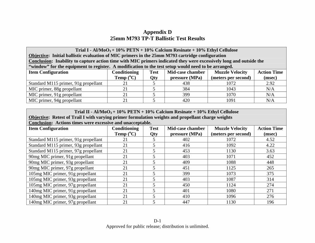
Measurement Appendix D is a tabulation of the ballistic performance of various MIC percussion
primers developed and tested. All test firings, with the exception of a small sample in Test Trial V which was fired from the M242 autogun, were fired from the 25mm Mann barrel setup as shown in Figure 18.

29 Approved for public release; distribution is unlimited.
Figure 18. 25mm Mann Barrel Test Setup at ARDEC Indoor Test Range
Test Trial I in March 2003 was a baseline experiment to determine the level of
performance offered by the initial MIC primer composition of Al/MoO3 + 10% PETN + 10% CR + 10% EC that emerged after the conclusion of the small caliber percussion primer study (Reference 1) and became the baseline for the start of the medium caliber percussion primer study. These experimental MIC primers were charged to a nominal weight of 159mg (scaled from the No. 41 primer) and, in essence, a propellant charge establishment test was conducted. Five rounds assembled with the standard M115 primer were shot simultaneously for comparison purposes. The target performance for the M793 cartridge was ~1100 m/sec muzzle velocity, ~400MPa mid-case chamber pressure and ~4.0msec projectile action time. The standard rounds performed within reasonable performance limits taking into account the hand assembly of the ammunition. The experimental MIC primed rounds on the other hand did not exhibit satisfactory performance. Subsequently, it was determined that the primer charge weight may have exceeded the volume of the primer cup when assembled with the anvil and pressed in the cartridge case. The theory was that the additional compaction of the anvil on the primer charge when the primer was pressed into the primer pocket of the cartridge case cracked the primer mix allowing some of the material to fall into the propellant bed during handling or disrupting the ignition of the primer mix during cartridge firing. A second test series was planned to address this suspected problem.
Test Trial II was conducted in June 2003 and was structured to evaluate the effect of MIC
primer charge weights and propellant charge weights on ballistic performance. The same baseline MIC formulation of Al/MoO3 + 10% PETN + 10% CR + 10% EC was prepared and cartridges made accordingly; including standard M115 primed rounds. A contoured primer
30 Approved for public release; distribution is unlimited.
composition consolidation punch was fabricated to maximize the amount of material that can be loaded into the primer cup without interference with the anvil during the case priming operation. Once again, the results of the standard primed rounds were acceptable while the action times of the MIC primed rounds were not. Although the MIC formulation tested showed promising results in limited small caliber ammunition firings, it was evident that additional work was required to make it suitable for medium caliber ammunition.
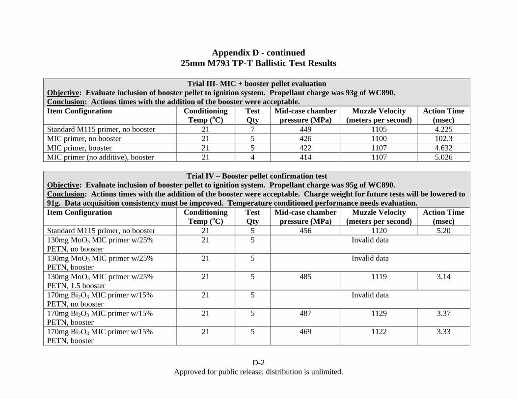
The first approach to evaluating supplements or changes to the baseline MIC primer
formulation introduced a booster pellet to the ignition system. The first evaluations of the MIC primer in 2003 purposely omitted the booster in order to evaluate the performance of the primer alone. Standard 25mm production cartridges include a booster between the primer and the propellant bed to aid the ignition propagation from the primer to the propellant. This booster is almost exclusively a 90% boron-potassium nitrate/10% fluid ball powder pellet nominally 111mg in weight. The lone exception was one particular configuration, no longer used, that consisted of black powder loaded into a brass flash tube. In March 2004, Test Trial III in this program was conducted looking at the baseline MIC formulation of Al/MoO3 + 10% PETN + 10% CR + 10% EC with the addition of a booster pellet. For comparison, standard M115 primed rounds as well as Al/MoO3 primed rounds without the gas generate additive were also fired. The experimental primers were made to a nominal charge weight of 130mg. The standard M115 rounds and one test group of MIC primed rounds were fired without a booster. The results were as predicted. The standard rounds and the boostered MIC rounds showed satisfactory performance while the unboostered MIC rounds did not. These results were promising, but the testing to date had yet to evaluate the contribution of extreme temperature conditioning.
Prior to evaluating the affect of extreme temperature conditioning on action time
performance, another test trial was planned to investigate the performance of different promising MIC formulations with the booster pellet at ambient conditions. Test Trial IV in November 2004 simplified the gas generate additive to PETN only and maximized the weight of the primary as allowed by the current dry loading conditions. The Al/MoO3 based primer contained 25% PETN by weight and was loaded at 130mg while the Al/Bi2O3 based primer contained 15% PETN by weight and was loaded at 170mg. The mass of the booster pellet was increased by 50% in some subgroups and the mass of the propellant was increased to 95g for all groups. Standard M115 primed cartridges without boosters were shot for comparison as customary to ascertain the integrity of the build process. Except for instrumentation error that plagued the test and prevented the reliable acquisition of action time data for a number of shots, all accurately recorded data was excellent. Analysis of the data also indicated that the propellant charge weights were much too high and would be reduced to the more common 91g level. At this point, temperature conditioning of the cartridges for ballistic evaluation was the next logical step.
The emerging primer formulation of choice was the Al/Bi2O3 containing PETN as the gas
generate additive. A sample of these primers, 150mg in weight, was made and assembled in M793 cartridges for temperature extreme performance testing. A single IB52 booster pellet was used to supplement the ignition system. Test Trial V was performed in March 2005 but resulted in unsatisfactory performance when cold conditioned. This cold performance, although disappointing, was not completely unexpected as cold temperature has routinely been the nemesis of interior ballistic performance of environmentally benign primers. The subsequent

31 Approved for public release; distribution is unlimited.
failure analysis identified the high concentration of PETN and low relative mass of the primer as the likely culprit. Concurrent with this failure analysis, ARDEC was seeking an extension to the SERDP project to investigate the merits of the water wet mixing process developed by the SDSMT in collaboration with the NSWC. The granted extension offered ARDEC the opportunity to modify the MIC primer composition to both suit the water mixing process and optimize ballistic performance. An added bonus of the water mix process was the substantially increased charge weight of the primer compared to the dry loading process. Taking advantage of this opportunity, the final MIC primer composition replaced PETN with RDX as the gas generate, an inert binder was added to the formulation to improve the consolidated integrity of the charge and the nominal charge weight was increased to nearly 300mg. In addition to the heavier primer, booster pellet weight was increased 100% to enhance the output into the propellant bed. A single booster pellet was positioned in the cartridge case in the conventional location while a second booster pellet, softened and reshaped with acetone, was placed between the conventional location booster and the anvil of the primer. Test Trial VI in April 2007 was the final ballistic evaluation of the primer developed under the SERDP sponsored program. Results across temperature extremes were excellent. Included in this test series were primers made in November 2005 and November 2006. There was no discernible difference in performance relative to the age of the primer thus giving initial indication that material degradation concerns may be alleviated with proper storage techniques. Although confirmatory data is not available as to exactly how these rounds successfully survived storage, a combination of the water wet processing technique with a hydration inhibitor, a consolidated primer charge, and environmentally sealed storage conditions (which mimics actual cartridge storage) allowed the rounds to perform acceptably 18 months after the cartridge cases were primed.
32 Approved for public release; distribution is unlimited.
4.0 Summary and Conclusions
The MIC morphology studies demonstrate the reaction rate appears to be dependent on factors such as the particle size, the size distribution, the aluminum oxide layer thickness, stoichiometry of the powder mix, the degree of intermixing of the powders, morphological characteristics and composition density. Convective transport is likely the dominant means of combustion while a conductive influence proportionally increases as the material packing densities increase to the point at which both play a significant role in the burning or consolidated percussion primer candidate formulations. Increased packing density of the material slows the reaction rate and may result in lower output pressure, but may help in reducing the sensitivity of the material and make it suitable for percussion primer application which requires a shock stimulus for ignition. Material consolidation in the primer assembly is critical in mitigating adverse oxidation of the nano aluminum fuel in the formulation.
Laboratory and ballistic tests reveal that MIC primers without a gas generate produce far
less pressure than the standard primer and are relatively slow in time to reach this pressure. The lower pressure output of the MIC primers without a gas generate can be expected to significantly affect the process of propellant ignition and pressure buildup within the cartridge. To obtain an acceptable pressure output, gas generating energetics were added to the basic MIC materials. This study shows that with the addition of gas generating material, MIC based percussion primers exhibit similar performance characteristics as standard primers when configured in the same cartridge system.
Collaborative studies with the NSWC, SDSMT and IMP has demonstrated that Al/Bi2O3
based MIC percussion primers can be safely made using water as the primary mixing and loading solvent. The wet loading process results in higher charge densities and the presence of hydration inhibitors are incorporated to mitigate adverse and undesirable fuel oxidation in the presence of its oxidizer during the mixing process in water.
Ballistic firings of the final composition made with the water wet mixing and loading
process exhibited satisfactory critical interior ballistic performance across the temperature extremes imposed on military ammunition.
All primers manufactured in this study were formulated in small batches of no more than
a few grams each. Logical progression of the work presented herein would be to scale up the manufacturing process of these environmentally acceptable percussion primers to substantially larger batch sizes or to a continuous flow type process. The formulation chosen would be more ideally suited for the continuous flow type process because of the stratification between the “heavy” bismuth trioxide and “light” aluminum that would naturally tend to occur in batch processing. This separation is mitigated to some degree with the gum arabic binder, but not enough to eliminate it entirely. Higher throughput of MIC primer material in the order of a ton/year, cartridge commodity design verification and qualification, final hazard classification, long term stability, insensitive munition contribution and impact, demilitization procedures and logistic concerns like packaging, transportation, handling and storage are still required to support medium caliber ammunition full scale production and get MIC primed ammunition into the hands of our armed forces.
A-1 Approved for public release; distribution is unlimited.
Appendix A. References
1. Middleton, J., “Elimination of Toxic Heavy Metals from Small Caliber Ammunition”, SERDP Final Report for Project PP-1057/78, (2000).
2. Sandstrom, M. M., Jorgensen, B.S., Smith, B.L., Mang, J.T., Son, S.F., Characterization of Ultra-fine Aluminum Nanoparticles, LA-UR-04-3954
3. Mang, J.T., Hjelm, R.P., Peterson, P.D., Jorgensen, B.S., Son, S.F. Characterization of Components of Nano-Energetics by Small-Angle Scattering Techniques, LA-UR-06-3251 4. Son, S.F., Asay, B.W., Mang, J.T., Bockmon, B.S., Pantoya, M.L., Combustion Velocities and Propagation Mechanisms of Metastable Interstitial Composites, Sep 2005, Journal of Applied Physics 98, 064903 (2005) 5. Son, S.F., Asay, B., Busse, J.R., Jorgenson, B.S., Bockmon, B.S, Pantoya, M.L., Reaction Propagation Physics of Al/MoO3 Nanocomposite Thermites, LA-UR-01-6075 6. Puszynski, J.A., Development of Al- Bi2O3 MIC Primer Water-Based Wet Loading Technique, Final Report for NSWC, Indian Head Division Contract N00174-05-M-0141, 31 May 2006 7. Higa, K.T., Energetic Nanocomposite Lead-Free Electric Primers, Journal of Propulsion and Power, Vol. 23, No. 4, July–August 2007 8. Son, S.F., Busse, J.R., Asay, B.W., Peterson, P.D., Mang, J.T., Bockmon, B., Pantoya, M.L., Propagation Studies of Metastable Intermolecular Composites (MIC), LA-UR-02-2954 9. Jorgensen, B., Busse, J., Smith, B., Son, S., Standard Characterization of MIC Materials, LA-UR-03-5944 10. Bockmon, B., Son, S.F., Asay, B.W., Busse, J.R., Mang, J.T., Peterson, P.D., Pantoya, M., Combustion Performance of Metastable Intermolecular Composites (MIC), LA-UR-02-2124 11. Sandstrom, M.M., Jorgensen, B.L., Mang, J.T., Smith, B.L., Son, S.F., Characterization of Ultrafine Aluminum Nanoparticles, LA-UR-04-2921

B-1 Approved for public release; distribution is unlimited.
Appendix B. Industry Standard Percussion Primer Drop Fixture.

C-1 Approved for public release; distribution is unlimited.
Appendix C. LANL Individual Shot Data
Shot No. % HE added to MIC Pmax (psi) Time to Pmax (μs) Ignition time (μs) Prate (psi/μs)
82103-A 4.8 833.2 652 196 1.8382503-B 4.8 983.6 488 76 2.3982503-C 4.8 846.0 504 64 1.92
92503-A 15 1539 536 92 3.4792503-B 15 1434.5 576 118 3.1392503-C 15 1430.9 380 136 5.86
92403-A 23 1906.8 504 136 5.1892403-B 23 1789.4 372 148 7.9992403-C 23 2091.3 344 100 8.57
92403-D 30 3073.7 200 22 17.2792403-E 30 2904.9 176 22 18.8692403-F 30 2868.2 304 118 15.42
80nm Al/MoO3+PETN
Shot No. % HE added to MIC Pmax (psi) Time to Pmax (μs) Ignition time (μs) Prate (psi/μs)
90203-A 4.8 896.1 532 84 2.0090203-B 4.8 784.1 588 68 1.5090203-D 4.8 820.3 584 84 1.64
92503-H 15 1654.3 548 132 3.9892503-I 15 1713.5 632 102 3.2392503-J 15 1491.7 708 82 2.38
90303-B 23 2086.2 580 60 4.0190303-C 23 2158.1 720 68 3.3190303-G 23 2145.9 804 72 2.93
92503-K 30 2546.9 488 142 7.3692503-L 30 2383.1 508 94 5.7692503-M 30 2418.3 452 148 7.95
80nm Al/MoO3+DAATOx
Shot No. % HE added to MIC Pmax (psi) Time to Pmax (μs) Ignition time (μs) Prate (psi/μs)
91203-A 4.8 749.7 256 52 3.6891203-B 4.8 791.8 244 96 5.3591203-D 4.8 758.8 360 196 4.63
92903-A 15 1272.6 388 119 4.7392903-C 15 1291.8 520 114 3.1892903-D 15 1203 568 180 3.10
91203-F 23 1817.0 600 256 5.28100203-H 23 1374.1 332 176 8.80100203-B 23 1406.2 632 182 3.12
91803-A 30 1719.2 1220 168 1.6391803-B 30 1647.5 1344 580 2.1691803-D 30 1659.2 1368 112 1.32
80nm Al/MoO3+BTATz

C-2 Approved for public release; distribution is unlimited.
Appendix C - continued. LANL Individual Shot Data
Shot No. % HE added to MIC Pmax (psi) Time to Pmax (μs) Ignition time (μs) Prate (psi/μs)
92903-H 4.8 805.2 320 28 2.7692903-I 4.8 712.5 332 64 2.6692903-J 4.8 720.5 232 96 5.30
92903-K 15 1234.5 404 66 3.6592903-L 15 1352.5 228 74 8.7892903-M 15 1301.1 284 132 8.55
93003-B 23 1589.7 192 28 9.6993003-C 23 1852.1 192 42 12.3593003-D 23 1850.5 200 46 12.02
93003-E 30 2043.4 196 32 12.4693003-G 30 2256.6 220 38 12.4093003-H 30 2235.1 220 46 12.85
80nm Al/MoO3+Nitrocellulose
Shot No. % HE added to MIC Pmax (psi) Time to Pmax (μs) Ignition time (μs) Prate (psi/μs)
122403-A 4.8 1181.3 438 222 5.47122403-B 4.8 1102.3 424 206 5.06122403-C 4.8 1077.6 404 188 5.00
122403-E 15 2632.5 374 145 11.50122403-F 15 2690.1 348 97 10.70122403-G 15 2547.4 260 113 17.33
10704-B 18 3566.2 292 211 44.0010704-C 18 3545.9 456 211 14.5010704-D 18 3725.9 422 267 24.00
122403-I 23 4360.2 324 91 18.70122403-J 23 4008.3 330 99 24.35122403-K 23 4028.5 376 149 17.75
122303-M 30 5786.6 374 176 29.22122303-N 30 6317.6 436 244 32.90122303-O 30 6294.4 434 241 32.60
80nm Al/Bi2O3+PETN

C-3 Approved for public release; distribution is unlimited.
Appendix C - continued. LANL Individual Shot Data
Shot No. % HE added to MIC Pmax (psi) Time to Pmax (μs) Ignition time (μs) Prate (psi/μs)
10704-E 4.8 1059.6 674 521 6.9010704-G 4.8 1059.4 558 405 6.9010704-H 4.8 1163.4 492 357 8.60
10704-J 15 2741.8 494 237 15.7010704-K 15 2214 426 329 22.8010704-L 15 2358.3 324 227 21.30
10704-Q 23 3733.0 514.0 287.0 26.4010704-S 23 3394.0 556.0 331.0 25.1010704-T 23 3409.8 480.0 249.0 15.80
10804-A 30 4766.2 332 115 25.1010804-C 30 4726.3 290 87 23.3010804-D 30 4601.8 294 91 22.70
80nm Al/Bi2O3+DAATOx
Shot No. % HE added to MIC Pmax (psi) Time to Pmax (μs) Ignition time (μs) Prate (psi/μs)
102403-B 4.8 907.8 296 38 3.52102403-C 4.8 873.1 216 40 4.96102403-D 4.8 832.9 172 20 5.48
102403-E 15 1422.7 244 92 9.36102403-F 15 1594.8 184 28 10.22102403-G 15 1590.3 200 38 9.82
102403-I 23 1943.6 224 46 10.92102403-J 23 2592.2 212 38 14.90102403-K 23 2450.0 224 42 13.46
102403-M 30 2808.7 240 62 15.78102403-N 30 3062.3 232 58 17.60102403-O 30 3111.6 228 54 17.88
44nm Al/MoO3+PETN

C-4 Approved for public release; distribution is unlimited.
Appendix C - continued. LANL Individual Shot Data
Shot No. % HE added to MIC Pmax (psi) Time to Pmax (μs) Ignition time (μs) Prate (psi/μs)
102403-Q 4.8 862.5 336 104 3.72102403-R 4.8 772 192 32 4.83102403-S 4.8 825.5 204 38 4.97
102403-T 15 1305.6 200 46 8.48102403-U 15 1264.2 276 110 7.62102403-V 15 1553.0 256 62 8.01
102403-X 23 2226.1 264 74 11.72102403-Y 23 2157.9 248 46 10.68
102403-AA 23 2221.2 244 68 12.62
102403-BB 30 3306.5 248 66 18.17102403-CC 30 3026.8 272 82 15.93102403-DD 30 2896.0 228 50 16.27
44nm Al/MoO3+DAATOx
Shot No. % HE added to MIC Pmax (psi) Time to Pmax (μs) Ignition time (μs) Prate (psi/μs)
100303-I 4.8 666.4 404 70 2.00100303-K 4.8 606.8 540 122 1.45100303-L 4.8 682.2 476 76 1.71
100303-N 15 1206.9 240 58 6.63100303-O 15 1258.8 464 222 5.20100303-P 15 1217.9 356 122 5.20
100303-Q 23 2300.7 596 230 6.29100303-R 23 2343.2 500 138 6.47100303-S 23 2339.9 684 130 4.22
100303-U 30 2607.7 576 104 5.52100303-V 30 2749.5 576 58 5.31100303-X 30 2836.9 544 208 8.44
121nm Al/MoO3+PETN

C-5 Approved for public release; distribution is unlimited.
Appendix C - continued. LANL Individual Shot Data
Shot No. % HE added to MIC Pmax (psi) Time to Pmax (μs) Ignition time (μs) Prate (psi/μs)
102803-B 4.8 488.3 528 292 2.07102803-C 4.8 631.3 784 504 2.25102803-D 4.8 563.0 792 546 2.29
102803-E 15 1344.8 500 202 4.51102803-F 15 1273.9 516 222 4.33102803-G 15 1324.4 584 158 3.11
91103-A 23 2390.3 680 120 4.2791103-B 23 2398.4 688 120 4.2291103-C 23 2818.2 620 124 5.68
102803-J 30 2496 532 138 6.34102903-C 30 2568.1 704 350 7.25102903-D 30 2702.8 484 126 7.55
121nm Al/MoO3+DAATOx
Shot No. % HE added to MIC
Particle size Al added Pmax (psi) Time to Pmax (μs) Ignition time (μs) Prate (psi/μs)
10504-A 4.8 201 977.0 415 210 4.7710604-J 4.8 473 1021.0 432 183 4.10
10504-B 15 201 2420.0 370 194 13.7010604-K 15 473 2735.0 381 202 15.25
10604-A 18 201 3671.0 372 180 19.1010604-H 18 473 3748.0 348 199 25.20
10504-C 23 201 4355.0 338 145 22.5610604-L 23 473 4372.0 354 190 26.66
10504-E 30 201 6087.0 415 217 30.7410604-M 30 473 5976.0 373 187 32.13
80nm Al/Bi2O3+PETN+Large Particle Size Al
D-1 Approved for public release; distribution is unlimited.
Appendix D 25mm M793 TP-T Ballistic Test Results
Trial I - Al/MoO3 + 10% PETN + 10% Calcium Resinate + 10% Ethyl Cellulose
Objective: Initial ballistic evaluation of MIC primers in the 25mm M793 cartridge configuration Conclusion: Inability to capture action time with MIC primers indicated they were excessively long and outside the “window” for the equipment to register. A modification to the test setup would need to be arranged. Item Configuration Conditioning
Temp (oC) Test Qty
Mid-case chamber pressure (MPa)
Muzzle Velocity (meters per second)
Action Time (msec)
Standard M115 primer, 91g propellant 21 5 438 1072 2.92 MIC primer, 88g propellant 21 5 384 1043 N/A MIC primer, 91g propellant 21 5 399 1070 N/A MIC primer, 94g propellant 21 5 420 1091 N/A
Trial II - Al/MoO3 + 10% PETN + 10% Calcium Resinate + 10% Ethyl Cellulose
Objective: Retest of Trail I with varying primer formulation weights and propellant charge weights Conclusion: Actions times were excessive and unacceptable. Item Configuration Conditioning
Temp (oC) Test Qty
Mid-case chamber pressure (MPa)
Muzzle Velocity (meters per second)
Action Time (msec)
Standard M115 primer, 91g propellant 21 5 402 1072 4.52 Standard M115 primer, 93g propellant 21 5 416 1092 4.22 Standard M115 primer, 97g propellant 21 5 453 1130 3.63 90mg MIC primer, 91g propellant 21 5 403 1071 452 90mg MIC primer, 93g propellant 21 5 409 1088 448 90mg MIC primer, 97g propellant 21 5 451 1125 265 105mg MIC primer, 91g propellant 21 5 399 1073 375 105mg MIC primer, 93g propellant 21 5 403 1087 314 105mg MIC primer, 97g propellant 21 5 450 1124 274 140mg MIC primer, 91g propellant 21 5 401 1080 271 140mg MIC primer, 93g propellant 21 5 410 1096 276 140mg MIC primer, 97g propellant 21 5 447 1130 196
D-2 Approved for public release; distribution is unlimited.
Appendix D - continued 25mm M793 TP-T Ballistic Test Results
Trial III- MIC + booster pellet evaluation
Objective: Evaluate inclusion of booster pellet to ignition system. Propellant charge was 93g of WC890. Conclusion: Actions times with the addition of the booster were acceptable. Item Configuration Conditioning
Temp (oC) Test Qty
Mid-case chamber pressure (MPa)
Muzzle Velocity (meters per second)
Action Time (msec)
Standard M115 primer, no booster 21 7 449 1105 4.225 MIC primer, no booster 21 5 426 1100 102.3 MIC primer, booster 21 5 422 1107 4.632 MIC primer (no additive), booster 21 4 414 1107 5.026
Trial IV – Booster pellet confirmation test
Objective: Evaluate inclusion of booster pellet to ignition system. Propellant charge was 95g of WC890. Conclusion: Actions times with the addition of the booster were acceptable. Charge weight for future tests will be lowered to 91g. Data acquisition consistency must be improved. Temperature conditioned performance needs evaluation. Item Configuration Conditioning
Temp (oC) Test Qty
Mid-case chamber pressure (MPa)
Muzzle Velocity (meters per second)
Action Time (msec)
Standard M115 primer, no booster 21 5 456 1120 5.20 130mg MoO3 MIC primer w/25% PETN, no booster
21 5 Invalid data
130mg MoO3 MIC primer w/25% PETN, booster
21 5 Invalid data
130mg MoO3 MIC primer w/25% PETN, 1.5 booster
21 5 485 1119 3.14
170mg Bi2O3 MIC primer w/15% PETN, no booster
21 5 Invalid data
170mg Bi2O3 MIC primer w/15% PETN, booster
21 5 487 1129 3.37
170mg Bi2O3 MIC primer w/15% PETN, booster
21 5 469 1122 3.33

D-3 Approved for public release; distribution is unlimited.
Appendix D - continued 25mm M793 TP-T Ballistic Test Results
Trial V – Al/Bi2O3 MIC Temperature Conditioning Test
Objective: Evaluate MIC + booster performance after temperature conditioning. Propellant charge was 91g of WC890. Conclusion: Cold temperature performance is unacceptable. M242 weapon stoppages are indicative of long action times. The hot condition weapon stoppage attributed to an improperly assembled primer; not the formulation itself. Item Configuration Conditioning
Temp (oC) Test Qty
Mid-case chamber pressure (MPa)
Muzzle Velocity (meters per second)
Action Time (msec)
Standard M115 primer, booster 21 10 403 1087 3.829 Standard M115 primer, booster -54 15 382 1055 3.958 Standard M115 primer, booster 62 15 430 1117 3.566 MIC primer w/20% PETN, booster 21 20 451 1088 4.500 MIC primer w/20% PETN, booster -54 20 431 1081 41.403 MIC primer w/20% PETN, booster 62 20 439 1114 3.869 MIC primer w/20% PETN, booster fired in M242 service weapon
-54 13 N/A N/A 3 stoppages
MIC primer w/20% PETN, booster fired in M242 service weapon
62 12 N/A N/A 1 stoppage

D-4 Approved for public release; distribution is unlimited.
Appendix D - continued 25mm M793 TP-T Ballistic Test Results
Trial VI – Final MIC Ballistic Test
Objective: Evaluate final formulation of water wet mixed Al/Bi2O3 MIC with RDX gas generate and 2 IB52 boosters. Propellant charge was 91g of WC890. Conclusion: Excellent performance. Item Configuration Conditioning
Temp (oC) Test Qty
Mid-case chamber pressure (MPa)
Muzzle Velocity (meters per second)
Action Time (msec)
Production M793 21 14 397 1076 4.100 Production M793 -54 14 391 1045 4.523 Production M793 62 14 426 1112 3.764 Standard M115 primer, booster 21 7 423 1077 4.020 Standard M115 primer, booster -54 4 411 1065 4.571 Standard M115 primer, booster 62 4 405 1093 3.750 2005 vintage MIC primer w/5% RDX, 1.5 booster
21 15 421 1089 3.587
2005 vintage MIC primer w/5% RDX, 2x booster
-54 15 415 1072 4.059
2005 vintage MIC primer w/5% RDX, 2x booster
62 15 417 1105 3.616
2006 vintage MIC primer w/5% RDX, 2x booster
21 15 420 1083 3.894
2006 vintage MIC primer w/5% RDX, 2x booster
-54 15 408 1065 4.315
2006 vintage MIC primer w/5% RDX, 2x booster
62 15 417 1102 3.703

E-1 Approved for public release; distribution is unlimited.
Appendix E. Primer Accidental Ignition Incident
A ten month shutdown of the MIC percussion primer program occurred between November 2005 and September 2006 when one of the MIC percussion primers accidentally ignited during the buildup for the final ballistic test series. This particular primer had just had the anvil pressed into the loaded and consolidated energetic material in the primer cup. The material at this stage of the operation is dry and thus susceptible to electrostatic discharge (ESD), impact and friction ignition. The operator was performing the primer assembly in accordance with the established standard operating procedures in place at the time including the proper safety precautions (with the exception of the presence of a second operator). The incident investigation concluded that the primer ignited from ESD. Post incident investigations revealed that the table on which the operation was being performed was not in compliance with the required conductivity requirements and was the most likely cause for the static charge buildup that ignited the primer. Actions to replace the faulty equipment prior to resumptions of activities added to the delay. An additional contributing factor, aside from the ESD potentially caused by the inadequate grounding of the table, was the excellent sample of bismuth trioxide attained from Accumet Materials. The uniformity of the particle size of the bismuth trioxide likely increased the sensitivity of the mixture. Revised standard operating procedures for handling and testing MIC material also resulted from the incident investigation.