Embed Size (px)
Citation preview

WSRC-SA-6 Rev 37
November 2018
FINAL SAFETY ANALYSIS REPORT
SAVANNAH RIVER SITE
DEFENSE WASTE PROCESSING FACILITY
VOLUME 6
NOVEMBER 2018

WSRC-SA-6 Rev 37
November 2018
ii
DISCLAIMER This document was prepared by AECOM N&E Technical Services, LLC (N&E TS) under contract with Savannah River Remediation, LLC (SRR), subject to the warranty and other obligations of that contract and in furtherance of SRR’s contract with the United States Department of Energy (DOE). N&E TS’ findings represent its reasonable judgments within the time and budget context of its commission and utilizing the information available to it at the time. This document was prepared solely for the DOE for Contract DE-AC09-09SR22505.
Release to and Use by Third Parties. As it pertains to releases of this document to third parties, and the use of or reference to this document by such third parties in whole or in part, neither N&E TS, SRR, DOE, nor their respective officers, directors, employees, agents, consultants, or personal services contractors (i) make any warranty, expressed or implied, (ii) assume any legal liability or responsibility for the accuracy, completeness, or usefulness, of any information, apparatus, product or process disclosed herein or (iii) represent that use of the same will not infringe privately owned rights. Reference herein to any specific commercial product, process, or service by trademark, name, manufacture or otherwise, does not necessarily constitute or imply endorsement, recommendation, or favoring of the same by N&E TS, SRR, DOE, or their respective officers, directors, employees, agents, consultants or personal services contractors. The views and opinions of the authors expressed herein do not necessarily state or reflect those of the United States Government or any agency thereof.
WSRC-SA-6 Rev 37
November 2018
FINAL SAFETY ANALYSIS REPORT SAVANNAH RIVER SITE DEFENSE WASTE PROCESSING FACILITY
CHAPTER 9
HAZARD AND ACCIDENT ANALYSES
November 2018
WSRC-SA-6 Rev 37
November 2018
9-i
CONTENTS
Page
9.0 HAZARD AND ACCIDENT ANALYSES ..................................................... 9.1-1
9.1 INTRODUCTION ............................................................................................ 9.1-1
9.1.1 Summary of DWPF Safety Analysis Programs .............................. 9.1-4
9.1.1.1 Preliminary Hazards Analysis.................................... 9.1-4
9.1.1.2 Defense in Depth Evaluation ..................................... 9.1-5
9.1.1.3 Functional Classification Analysis ............................ 9.1-5
9.1.1.4 Design Basis Analysis................................................ 9.1-5
9.1.1.5 Probabilistic Safety Analysis - Design Verification ................................................................ 9.1-6
9.1.1.6 512-S Facility Consolidated Hazard Analysis... ........ 9.1-6
9.1.1.7 DWPF Consolidated Hazard Analysis .............. ........ 9.1-7
9.1.1.8 Consolidated Hazard Analysis for the Resolution of PISA: PI-05-006-NI-DWPF-05-001, Unanalyzed Hydrogen Vapors Impacts.............. ......................................................... 9.1-8
9.1.1.9 Deleted ....................................................................... 9.1-8
9.1.1.10 Defense in Depth/Important to Safety Control Selection ..................................................................... 9.1-8
9.1.1.11 Deleted ....................................................................... 9.1-9
9.1.1.12 REDC Cleaning and Process Enhancements CHA.............. ............................................................. 9.1-9
9.1.1.13 LWPT and LWHT Sampling Process CHA .. ............9.1-9
9.1.1.14 Interim Canister Storage Double Stack CHA..............9.1-9
9.1.2 Chapter Organization .................................................................... 9.1-10
9.1.3 Summary of Accident Analysis Results ....................................... 9.1-10
9.2 REQUIREMENTS ............................................................................................ 9.2-1
WSRC-SA-6 Rev 37
November 2018
9-ii
CONTENTS (Continued)
Page
9.3 HAZARDS ANALYSES .................................................................................. 9.3-1
9.3.1 Methodology ................................................................................... 9.3-2
9.3.1.1 PHA Methodology ..................................................... 9.3-2
9.3.1.2 Consolidated Hazard Analysis Methodology ........... 9.3-7
9.3.2 Hazard Analysis Results ............................................................... 9.3-15
9.3.2.1 PHA Hazard Analysis Results ................................. 9.3-15
9.3.2.2 Consolidated Hazard Analysis Hazard Results ....... 9.3-28
9.3.3 Planned Design and Operational Safety Improvements ............... 9.3-36
9.4 ACCIDENT ANALYSIS.................................................................................. 9.4-1
9.4.1 Analysis Methodology .................................................................... 9.4-1
9.4.1.1 Scenario Development Methodology ........................ 9.4-1
9.4.1.2 Source Term Analysis Methodology ......................... 9.4-2
9.4.1.3 Consequence Analysis Methodology ....................... 9.4-22
9.4.1.4 Acceptance Criteria .................................................. 9.4-25
9.4.2 Evaluation of Accidents ................................................................ 9.4-27
9.4.2.1 Explosions in the CPC/SPC Vessels ........................ 9.4-31
9.4.2.2 Explosions in 512-S ................................................. 9.4-42
9.4.2.3 Explosions in the Melter Off-Gas ............................ 9.4-44
9.4.2.4 Explosions in the LPPP Vessels .............................. 9.4-48
9.4.2.5 Steam Explosions in the Melter ............................... 9.4-52

WSRC-SA-6 Rev 37
November 2018
9-iii
CONTENTS (Continued)
Page
9.4.2.6 Interarea Transfer Line Explosions .......................... 9.4-55
9.4.2.7 Loss of Containment in the Process Cells................ 9.4-60
9.4.2.8 Loss of Containment in the Low Point Pump Pit .... 9.4-64
9.4.2.9 Interarea Transfer Line Loss of Containment .......... 9.4-69
9.4.2.10 Loss of Melter Containment/Confinement .............. 9.4-71
9.4.2.11 Uncontrolled Reactions in the Process Cells ........... 9.4-75
9.4.2.12 Criticality ................................................................. 9.4-77
9.4.2.13 Earthquake ............................................................... 9.4-80
9.4.2.14 High Winds .............................................................. 9.4-91
9.4.3 Beyond Design Basis Accidents ................................................. 9.4-100
9.4.3.1 Beyond Design Basis Accidents - Radiological Consequences ......................................................... 9.4-101
9.4.3.2 Beyond Design Basis Accidents - Chemical Consequences ......................................................... 9.4-103
9.5 REFERENCES ................................................................................................. 9.5-1
9.6 TABLES ........................................................................................................... 9.6-1
9.7 FIGURES .......................................................................................................... 9.7-1
WSRC-SA-6 Rev 37
November 2018
9-iv
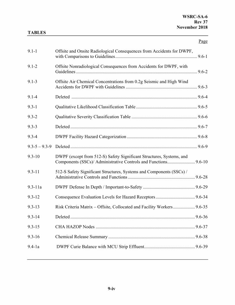
TABLES
Page
9.1-1 Offsite and Onsite Radiological Consequences from Accidents for DWPF, with Comparisons to Guidelines ....................................................................... 9.6-1
9.1-2 Offsite Nonradiological Consequences from Accidents for DWPF, with Guidelines ......................................................................................................... 9.6-2
9.1-3 Offsite Air Chemical Concentrations from 0.2g Seismic and High Wind Accidents for DWPF with Guidelines .............................................................. 9.6-3
9.1-4 Deleted ............................................................................................................. 9.6-4
9.3-1 Qualitative Likelihood Classification Table ..................................................... 9.6-5
9.3-2 Qualitative Severity Classification Table ......................................................... 9.6-6
9.3-3 Deleted .............................................................................................................. 9.6-7
9.3-4 DWPF Facility Hazard Categorization ............................................................. 9.6-8
9.3-5 – 9.3-9 Deleted .............................................................................................................. 9.6-9
9.3-10 DWPF (except from 512-S) Safety Significant Structures, Systems, and Components (SSCs)/ Administrative Controls and Functions........................ 9.6-10
9.3-11 512-S Safety Significant Structures, Systems and Components (SSCs) / Administrative Controls and Functions .......................................................... 9.6-28
9.3-11a DWPF Defense In Depth / Important-to-Safety ............................................. 9.6-29
9.3-12 Consequence Evaluation Levels for Hazard Receptors .................................. 9.6-34
9.3-13 Risk Criteria Matrix – Offsite, Collocated and Facility Workers ................... 9.6-35
9.3-14 Deleted ............................................................................................................ 9.6-36
9.3-15 CHA HAZOP Nodes ...................................................................................... 9.6-37
9.3-16 Chemical Release Summary ........................................................................... 9.6-38
9.4-1a DWPF Curie Balance with MCU Strip Effluent ............................................ 9.6-39
WSRC-SA-6 Rev 37
November 2018
9-v
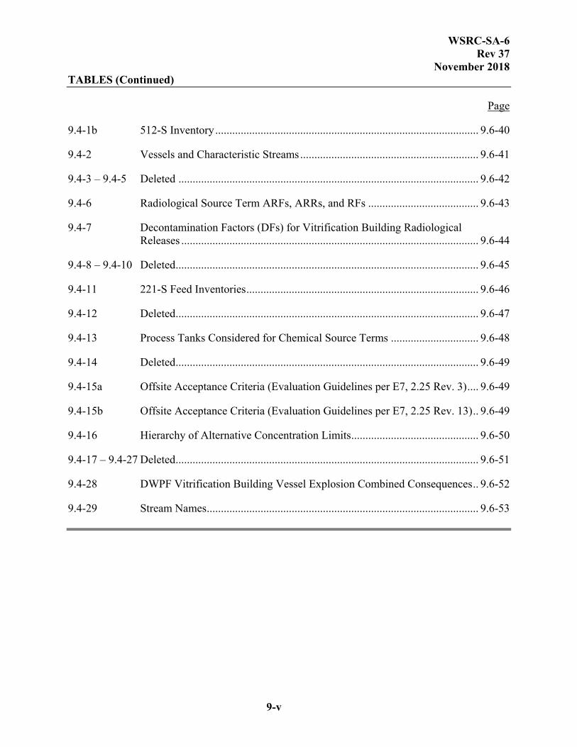
TABLES (Continued)
Page
9.4-1b 512-S Inventory ............................................................................................. 9.6-40
9.4-2 Vessels and Characteristic Streams ............................................................... 9.6-41
9.4-3 – 9.4-5 Deleted .......................................................................................................... 9.6-42
9.4-6 Radiological Source Term ARFs, ARRs, and RFs ....................................... 9.6-43
9.4-7 Decontamination Factors (DFs) for Vitrification Building Radiological Releases ......................................................................................................... 9.6-44
9.4-8 – 9.4-10 Deleted ........................................................................................................... 9.6-45
9.4-11 221-S Feed Inventories .................................................................................. 9.6-46
9.4-12 Deleted ........................................................................................................... 9.6-47
9.4-13 Process Tanks Considered for Chemical Source Terms ............................... 9.6-48
9.4-14 Deleted ........................................................................................................... 9.6-49
9.4-15a Offsite Acceptance Criteria (Evaluation Guidelines per E7, 2.25 Rev. 3) .... 9.6-49
9.4-15b Offsite Acceptance Criteria (Evaluation Guidelines per E7, 2.25 Rev. 13) .. 9.6-49
9.4-16 Hierarchy of Alternative Concentration Limits ............................................. 9.6-50
9.4-17 – 9.4-27 Deleted ........................................................................................................... 9.6-51
9.4-28 DWPF Vitrification Building Vessel Explosion Combined Consequences .. 9.6-52
9.4-29 Stream Names ................................................................................................ 9.6-53

WSRC-SA-6 Rev 37
November 2018
9-vi
FIGURES
Page
9.1-1 Overview of Interrelationship of DWPF Safety Documentation ...................... 9.7-1
9.3-1 Three-by-Three Frequency and Consequence Matrix for Hazard Evaluation ............................................................................................. 9.7-2
9.4-1 Process Chemical Screening Methodology ...................................................... 9.7-3

WSRC-SA-6 Rev 37
November 2018
9.1-1
9.0 HAZARD AND ACCIDENT ANALYSES
9.1 INTRODUCTION
This Final Safety Analysis Report (FSAR) encompasses operations at the Defense Waste Processing Facility (DWPF), including the Actinide Removal Process (ARP) performed in 512-S. Chapter 9 identifies and assesses potential hazards associated with DWPF operations. Figure 9.1-1 provides an overview of the hazard and accident analyses, and illustrates the relationship of these analyses. The hazard analyses presented in Section 9.3 are used as the basis for identification of Safety Significant (SS) Structures, Systems, and Components (SSCs) and administrative controls to protect the onsite receptor. The design basis analyses presented in Section 9.4 are used for identification of Safety Class (SC) and SS SSCs and administrative controls to protect the offsite public and onsite receptor.
The initial hazard analysis for DWPF was performed using the Preliminary Hazards Analysis (PHA) (Ref. 5) and Functionally Classified using Reference 3. The subsequent 512-S hazard analysis (Ref. 120) was performed under the Consolidated Hazard Analysis Process (CHAP) (Ref. 221) and Functionally Classified using Reference 132. The hazard analysis associated with the modifications to integrate MCU, 241-96H, and ARP as well as the utilization of bubblers in the melter and potential flammability hazards from retained hydrogen and antifoam degradation products (ADPs) (Ref. 169) was performed using CHAP (Ref. 221) and followed the Functional Classification of Reference 215. The three hazard analyses are similar in methodologies and output results, with the major difference being the binning of hazards. The criteria used to determine the bin and thus the control strategy is different between the PHA and the Consolidated Hazard Analysis (CHA). Hazard Analysis (HA) as used in this document, refers to the hazard analysis (PHA and CHA) performed for the above facilities. Further evaluation of the functional classification of safety related controls related to chemical processes identified by the PHA was performed in Reference 183.
Additional HAs have been performed for more limited scope activities/modifications and are described below:
A CHA (Ref. 179) was conducted to evaluate hazards associated with confined hydrogen explosions in Non-Safety Related SSCs – Interaction Sources that could interact with safety related equipment. The methodology employed in this CHA is the What-If methodology and was conducted in accordance with Reference 168. Functional Classification of controls associated with this CHA were determined in accordance with Manual E7, Procedure 2.25 Revision 3 as supplemented by Attachment 8.8 of Manual E7, Procedure 2.25 Revision 14 (Ref. 3 and 162) as well as E7 Manual Waiver Request E7-018 (Ref. 180).
For Decontaminated Equipment and Waste Staging (DEWS), design basis analysis calculations (Ref. 159 and 197) using source terms based on bounding radioactive material inventories, determined that no Safety Class or Safety Significant controls were warranted for the containers (SeaLand or equivalent) or for the area where these

WSRC-SA-6 Rev 37
November 2018
9.1-2
containers are stored. These evaluations included the decontaminated equipment intended for reuse and the glass-contaminated equipment.
For the staged waste, the structural integrity of the waste containers is maintained per the Waste Certification Plan (Ref. 161), and it is assumed that no catastrophic failure of the waste containers occurs. No controls other than those protecting the assumed initial condition regarding waste container structural integrity are required to prevent catastrophic failure of the waste containers. Therefore, no additional hazards analysis was performed.
A CHA was conducted for REDC Cleaning and Process Enhancements (Ref. 205). This CHA evaluated the hazards associated with the process enhancement(s) to the REDC including the use of the electric steam boiler to provide steam to the REDC. This CHA was conducted in accordance with Reference 216.
A CHA was conducted for the Late Wash Precipitate Tank (LWPT) and Late Wash Hold Tank (LWHT) sampling process (Ref. 208). This CHA evaluated the sampling of the LWPT and LWHT in the 512-S facility. This process included multiple grab samples taken from each vessel over the course of several days. This activity occurred with 512-S cell covers removed and agitation actively occurring within the vessels. The CHA also evaluated the accumulation of sample vials in the facility prior to being taken to the laboratory for analysis. This CHA was conducted in accordance with References 168 and 193.
A CHA was conducted for Interim Canister Storage Double Stack (Ref. 210). This CHA evaluated the hazards associated with the modifications to GWSB #1 to allow two canisters per storage position, as well as hazards associated with the placement and storage of double the number of canisters. This CHA was conducted in accordance with Reference 212.
HAZARDS ANALYSIS
Accidents stemming from the hazards associated with DWPF operations are postulated, and their frequencies of occurrence and consequences evaluated qualitatively in a HA. The PHA and CHAP perform the following functions except as noted:
Systematically identifies and qualitatively assesses the hazards that are present within the facility.
Evaluates the potential for hazards to develop into accidents.
Identifies an initial set of prevention, detection and mitigation features that form the starting point for the performance of a detailed Defense-In-Depth Evaluation (DIDE). (PHA only)
Bins each hazard according to frequency of occurrence and severity of consequence.
For PHA hazards binned as moderate and high consequence accidents for onsite or offsite receptors as determined by the PHA, a separate, more detailed evaluation of the lines of defense was performed in a DIDE (Ref. 2). SSCs that make up lines of defense were considered as candidates for SC and SS items for the functional classification process (Ref. 3 and 4). SS SSCs

WSRC-SA-6 Rev 37
November 2018
9.1-3
and Technical Safety Requirement (TSR) administrative controls for the LPPP, Vitrification Building, FESV and GWSBs are presented in Table 9.3-10. For the hazards binned as moderate- and high-consequence accidents for the offsite public, rigorous quantitative analyses were performed, and these include the design basis analyses and the Probabilistic Safety Analysis (PSA) (Ref. 1). These events are described in Section 9.4.
For the CHAs, events are binned according to frequency/risk rating of the event. Since the inception of the CHA Process, guidance (e.g., risk schemes) has changed to reflect updated DOE requirements. The basic fundamentals of the HA process are presented in this section and the associated Controls Selection Criteria Matrices are presented in Table 9.3-13 which was used in the primary CHAs for the facility (Ref. 120 and 169). Subsequent CHAs (Ref. 179, 205, 208, and 210) contain the specific details of the methodology utilized and the specific Controls Selection Criteria Matrices that are applicable.
The accidents selected in the HA process with potentially significant consequences to the offsite public and the bounding accident identified for each accident type are considered to be Design Basis Accidents (DBAs), or accident classes. The DBAs also include natural phenomena and external events, as applicable.
For each DBA, bounding unmitigated scenarios are defined, and the offsite and onsite receptor consequences are calculated assuming failure of all possible SSC boundaries that could prevent or mitigate the release of hazardous material. The offsite consequence is compared to the Evaluation Guidelines (EGs) (see Table 9.4-15a (PHA) and Table 9.4-15b (CHAP)) and the onsite receptor consequence is compared to the DOE-EM Interim Guidance Evaluation Guideline (IGEG) from DOE-EM (Ref. 185). If the offsite EGs are challenged or IGEG for the onsite receptor is exceeded, mitigative or preventive SSCs or administrative controls are defined whose functions are expected to reduce the consequences below the EGs or IGEG. The unmitigated DBA consequences are re-analyzed, and if necessary, additional SSCs or controls are added until the consequences are below the EGs or IGEG. SSCs and administrative controls required to bring the unmitigated offsite and onsite receptor consequences below the EGs and IGEG are identified as SC and/or SS equipment and administrative controls, and are subject to TSR controls. The mitigated scenario is also presented, re-analyzing the DBA with credit given to SC and SS equipment. These consequences are shown to be well below the EGs and less than the IGEG. SC and SS SSCs and TSR controls are presented on a per-accident basis in Section 9.4.2.
DESIGN VERIFICATION
The DBAs described above take unconditional credit for the SC and SS equipment. The effects associated with failure of SC and SS equipment are addressed in a PSA (Ref. 1). This analysis provides verification of the adequacy of the design basis. The PSA quantifies the probabilities of failure for SC, SS, and non-safety SSCs. This analysis also incorporates human reliability considerations. The analysis results in quantitative estimates of accident progression frequencies and uses a frequency/consequence model that observes a credibility cutoff at the lower end of the extremely unlikely range (1E-06 per year).

WSRC-SA-6 Rev 37
November 2018
9.1-4
9.1.1 SUMMARY OF DWPF SAFETY ANALYSIS PROGRAMS
The analyses performed to identify the safety related SSCs and to demonstrate the effectiveness of the DWPF design in accident prevention and mitigation are summarized below. Figure 9.1-1 provides an overview of the hazard and accident analysis process, illustrating the relationship of these analyses, which include the following:
PHA
DIDE
Functional Classification Analysis
Design Basis Analysis
PSA
CHAs
Each component is described below to summarize its purpose, approach, and interrelationship with other analyses.
9.1.1.1 Preliminary Hazards Analysis
A PHA was conducted to identify DWPF hazards, to postulate potential accident classes involving these hazards, and to assess their consequences and frequencies (Ref. 5). The PHA identifies the potential hazards at DWPF and then postulates events involving these hazards. Events considered typically involved failures to detect deviations from normal process conditions, failures to prevent an accident once a process upset has occurred, or failures to mitigate the consequences of an accident. Accident classes involving these postulated events were then evaluated qualitatively to estimate the resulting frequencies and consequences. The qualitative frequency and consequence results are used to screen out events that have minimal impacts on the safety of facility workers and the offsite public.
Those potential accident classes that survive screening in the qualitative PHA evaluations define the accident classes that are subjected to the following additional analyses.
More detailed quantitative consequence analysis (i.e., the design basis analysis); accident classes evaluated from a probabilistic-based analysis (i.e., the design verification PSA)
DIDE
Further evaluation of the functional classification of safety related controls related to chemical processes identified by the PHA was performed in Reference 183. This evaluation identified some previously credited chemical controls which are not related to radiological processes as Standard Industrial Hazards (SIHs) and thus do not require accident analysis and functional classification.

WSRC-SA-6 Rev 37
November 2018
9.1-5
9.1.1.2 Defense in Depth Evaluation
The DIDE performed a systematic review of the hazards and accidents postulated in the hazard analyses for the purpose of identifying SSCs and administrative controls that provide mitigative or protective functions or Lines of Defense (LODs) related to the safety of the facility worker and the offsite public (Ref. 2). The review was performed for the credible accidents that the PHA identified as having a potential for moderate or high radiological or chemical consequences to the facility worker or to the offsite public. For each accident, SSCs and administrative controls were identified that could prevent or mitigate the consequence of the event. From the identified SSCs and administrative controls, LODs were identified that provide layers of protection available to prevent the uncontrolled release of hazardous material. SS and SC items are selected from the identified LODs as part of the functional classification analysis.
An evaluation was also performed to determine if Non-SC/SS Defense-In-Depth SSCs or administrative controls are required to be identified per AB Steering Committee Guidance Document #301-01. The evaluation concludes that Non-SC/SS SSCs or administrative controls are not required since the consequences associated with offsite accidents do not exceed the guidance criteria when credit is taken for SC and SS SSCs and/or TSRs (Ref. 109).
9.1.1.3 Functional Classification Analysis
The functional classification analysis assesses the hazards and accidents that were identified as significant from the DIDE and selects from the LODs to define the SC and SS SSCs and administrative controls (Ref. 4). These features and controls provide protection for facility workers and the offsite public. In addition, the functional classification analysis, in conjunction with the design basis analysis, identifies the SC and SS SSCs and administrative controls that are required to maintain potential accident consequences to the offsite public and onsite receptor to within their respective EGs or IGEGs.
The functional classification analysis documents the integration of the various analyses and programs that have been conducted to define the full set of SC and SS SSCs and administrative controls, which form the basis for the TSRs in Chapter 11 of this FSAR.
The resultant lists of these SSCs are provided in Table 9.3-10 (excluding 512-S), and Section 9.4.2 of this chapter and in Chapter 4 of this FSAR.
9.1.1.4 Design Basis Analysis
The design basis analysis assesses the accident classes from the PHA with potentially significant consequences to the offsite public to define DBAs. In addition to the candidate accidents from the HA, significant natural phenomena and external events are analyzed as DBAs. The functional classification analysis, the detailed probabilistic safety analysis performed for design verification, the 512-S CHA (Ref. 120) and the DWPF CHA (Ref. 169) were also inputs to the selection of the DBAs. The analyses for the DBAs are presented in Section 9.4.2.
WSRC-SA-6 Rev 37
November 2018
9.1-6
For each DBA, bounding unmitigated scenarios are defined. The scenario takes no credit for safety features or controls. The bounding unmitigated scenarios are chosen based on insights and key initiators. The bounding unmitigated scenario results in bounding offsite and onsite receptor consequences, which are intended to also encompass the consequences of other possible scenarios for this accident class. The scenario description for each DBA includes a listing of all key initiators that are important to the accident progression and identifies the preventive and mitigative functions for these initiating events. These preventive and mitigative functions are used to define the SC and SS SSCs and administrative controls, which are credited in the design basis analysis to arrive at the SC/TSR mitigated scenario.
For each bounding unmitigated DBA scenario an offsite and onsite receptor consequence analysis is performed. The offsite consequences are compared to the evaluation guidelines; if the EGs are exceeded, SC mitigative or preventive SSCs or TSR administrative controls are defined and credited in the mitigated DBA scenario. The onsite receptor consequences are compared to IGEG from DOE-EM (Ref. 185). If the IGEG is exceeded, SS mitigative SSCs, preventive SSCs, or TSR administrative controls are defined and credited in the mitigated DBA scenario. The scenario is reevaluated to show that the mitigated DBA reflects those credits, and the consequences are shown to be well below the EGs or DOE-EM IGEG as applicable.
9.1.1.5 Probabilistic Safety Analysis - Design Verification
The PSA provides verification that the set of SC SSCs and TSR controls established from the design basis analysis is sufficient to assure that potential offsite consequences are within Risk Guidelines and represent an adequate safety authorization basis for DWPF, and that the DWPF design and planned operations result in acceptable risk to the offsite public. The PSA provides a complete logical/consequence model of the as-designed DWPF that demonstrates acceptable facility safety performance under all credible accident conditions.
The PSA was then used to guide the selection of Design Basis Accidents (DBAs). Highly probable events were considered in conjunction with the high and moderate frequency events specified in the PHA (see Section 9.4.2) to establish the DBAs. Events with extremely low (1.0E-08 thru 1.0E-09) frequencies were screened from DBA selection. The PSA was also used to determine the beyond design basis accidents to assure no high consequence incredible accidents were immediately adjacent to the 1.0E-6 frequency cutoff (see Section 9.4.3).
NOTE: A PSA was not part of the CHAs conducted for the facility.
9.1.1.6 512-S Facility Consolidated Hazard Analysis
A Consolidated Hazard Analysis (CHA) was conducted to identify potential hazardous events applicable to 512-S. Part of the process is to select appropriate control strategies that eliminate the hazards and resultant hazardous situations, reduce likelihood of occurrence of the event, or mitigate the consequences of the event (Ref. 120).
The HAZOP analysis methodology was the technique chosen to conduct the unmitigated hazard analysis. A multidisciplinary team uses prescribed protocol to review input documents such as, process/facility design, drawings, and procedures and evaluate significant deviations from
WSRC-SA-6 Rev 37
November 2018
9.1-7
normal design intentions. The HAZOP process divides the process into logical segments called “Nodes”. The CHAP team examines each node for potential hazardous process deviations that are derived from a set of established guidewords. Each guideword is combined with the relevant process parameters and applied to each node in the process being examined. HAZOP guidewords were used to provide structure to the HA and stimulate the identification of hazards and hazardous situations.
The unmitigated hazard analysis was performed using the HAZOP analysis technique to develop the risks involved with the facility and its associated operations without regard for any safety controls or programs. Unmitigated refers to the determination of the frequency and consequences without credit given for preventive or mitigative features. Controls are then assigned and designated as SC or SS depending on the receptor (offsite or onsite). During the unmitigated HA, the Material at Risk (MAR) equaled the available hazardous inventory that could be acted upon during the postulated event.
There were no ARP events, which tripped any offsite guideline. Events that tripped an onsite guideline require a set of controls appropriate to the level of risk and the receptor. The resultant SSCs are documented in Table 9.3-11, and Section 9.4.2 of this chapter and in Chapter 4 of this FSAR.
9.1.1.7 DWPF Consolidated Hazard Analysis
A Consolidated Hazard Analysis (CHA) was conducted to identify potential hazardous events mainly associated with the modifications to integrate MCU and 241-96H into DWPF but also evaluated the hazards associated with the transfer lines and leak detection boxes, utilization of bubblers in the melter and the potential for hydrogen retention and flammable ADPs in several of the vessels. The locations analyzed included Interarea Transfer Lines, LPPP, Vitrification Building, GWSBs and FESV. Part of the process is to select appropriate control strategies that eliminate the hazards and resultant hazardous situations, reduce likelihood of occurrence of the event, or mitigate the consequences of the event (Ref. 169). A combination of the HAZOP and What-If Analysis methodologies was chosen to conduct the unmitigated hazard analysis. The HAZOP analysis technique is described in Section 9.1.1.6. The What-If Analysis technique is a brainstorming approach in which a group of experienced people familiar with the process being analyzed ask questions or voice concerns about possible undesired events.
Events whose risk challenges the Offsite EGs are subjected to further detailed quantitative accident analyses (AA) and are candidates for Design Basis Accidents (DBAs). During the AA, the event consequences are reviewed to identify areas where the input parameters (MAR, DR, ARF, etc.) can be reduced, with the new consequence values documented. If the risk still challenges the Offsite EGs, SC functions are identified to bring the risk sufficiently below the EGs for the Offsite receptor.
Events that exceeded the onsite guidelines require a set of controls appropriate to the level of risk to the workers. The resultant SS SSCs and administrative controls to ensure worker safety are documented in Table 9.3-10 and Table 9.3-11 of this chapter and in Chapter 4 and Chapter 11 of this FSAR.

WSRC-SA-6 Rev 37
November 2018
9.1-8
With the analysis of the flammable hazards associated with hydrogen retention, ADPs, and the melter off-gas system, a different control scheme was identified from previous vessel explosion events in the Vitrification Building. Due to vulnerabilities in the controls related to these hazards, Zone 1 Ventilation is credited as the primary control to mitigate the event consequences. While analyzing the ability of Zone 1 Ventilation to perform its safety function following vessel explosions, it became apparent that vessel explosions could result in significant damage to the structures, systems, and components in the Vitrification Building. Although the Zone 1 Ventilation system would continue to perform its safety function by directing contamination through the Safety Significant sand filter, the damage inside the Vitrification Building could have a long-term impact on the ability of DWPF to perform its mission.
9.1.1.8 Consolidated Hazards Analysis for the Resolution of PISA: PI-05-006-NI-DWPF-05-001, Unanalyzed Hydrogen Vapors Impacts
A CHA was conducted to evaluate hazards associated with confined hydrogen explosions in Non-Safety Related SSCs – Interaction Sources that could interact with safety related equipment. Part of the process is to select appropriate control strategies that eliminate the hazards and resultant hazardous situations, reduce likelihood of occurrence of the event, or mitigate the consequences of the event (Ref. 179). The What-If analysis methodology was the technique chosen to conduct the unmitigated hazard analysis.
The What-If Analysis technique is a brainstorming approach in which a group of experienced people familiar with the process being analyzed ask questions or voice concerns about possible undesired events. Given that the process areas of concern have an existing hazard analysis and design basis analysis, this method is appropriate to apply a graded approach for analyzing the hazards associated with confined hydrogen.
The CHAP determined that explosive events in certain non-safety related SSCs can lead to design basis accident scenarios. Based on a waiver to Manual E7, 2.25 (Ref. 180) to extend the seismic interaction criteria to include explosive interaction on safety SSCs, these identified sources have been classified as PS. The resultant controls to prevent impact on safety related SSCs are documented in Chapter 4 and Chapter 11 of this FSAR.
9.1.1.9 Deleted
9.1.1.10 Defense in Depth/Important to Safety Control Selection
Table 9.3-11a lists Defense In Depth (DID)/Important-To-Safety (ITS) hazard controls. These were selected from the suite of controls in the supporting hazards analyses. No specific credit is given to these controls insofar as event frequency or consequence reduction, nor is any margin of safety assigned to these controls. However, by being listed in Table 9.3-11a, the facility commits to ensuring that each additional defense in depth hazard control is installed. Additionally, since these controls are not included in the Technical Safety Requirements (TSR), facility operations may continue with these additional defense in depth hazard controls temporarily out of service as permitted and managed by existing site procedures, facility procedures, and Safety Management Programs.

WSRC-SA-6 Rev 37
November 2018
9.1-9
9.1.1.11 Deleted
9.1.1.12 REDC Cleaning and Process Enhancements CHA
A CHA was conducted to evaluate hazards associated with the installation of an electric steam generator (boiler) to support decontamination activities of equipment in the REDC. Part of the process is to select appropriate control strategies that eliminate the hazards and resultant hazardous situations, reduce likelihood of occurrence of the event, or mitigate the consequences of the event (Ref. 205). The What-If analysis methodology was the technique chosen to conduct the unmitigated hazards analysis.
The What-If Analysis technique is a brainstorming approach in which a group of experienced people familiar with the process being analyzed ask questions or voice concerns about possible undesired events. Given that the process areas of concern have an existing hazard analysis and design basis analysis, this method is appropriate to apply a graded approach for analyzing the hazards associated with the operation of the boiler for decontamination activities.
The CHAP determined that no safety -related controls were required due to the installation of the boiler in the REDC since no events resulted in challenging or exceeding offsite or onsite evaluation guidelines (Ref. 205).
9.1.1.13 LWPT and LWHT Sampling Process CHA
A CHA was conducted to evaluate hazards associated with the sampling of the LWPT and LWHT with 512-S cell covers removed and agitation active within the vessels. Additionally, the accumulation of sample vials in the facility before being taken to the laboratory was also evaluated. Part of the process is to select appropriate control strategies that eliminate the hazards and resultant hazardous situations, reduce likelihood of occurrence of the event, or mitigate the consequences of the event (Ref. 208). The What-If analysis methodology was the technique chosen to conduct the unmitigated hazards analysis.
The What-If Analysis technique is a brainstorming approach in which a group of experienced people familiar with the process being analyzed ask questions or voice concerns about possible undesired events. Given that the process areas of concern have an existing hazard analysis and design basis analysis, this method is appropriate to apply a graded approach for analyzing the hazards associated with the sampling of the LWPT and LWHT.
The CHAP determined that no safety related controls were required due to the sampling of the LWPT and LWHT since no events resulted in challenging or exceeding offsite or onsite evaluation guidelines (Ref. 208).
9.1.1.14 Interim Canister Storage Double Stack CHA
GWSB #1 is capable of storing two canisters per storage location after undergoing modifications as determined by this CHA. The CHA analyzes new hazards associated with the process of modifying the GWSB #1 vaults to support double stacking canisters, as well as hazards
WSRC-SA-6 Rev 37
November 2018
9.1-10
associated with the placement and storage of twice the number of canisters, per GWSB #1, as currently analyzed in the DWPF Safety Basis (Ref 210). The hazard evaluation first performs a comprehensive unmitigated hazard analysis to identify and develop specific events and scenarios associated with a hazardous release, estimates the event frequency and consequences, and identifies potential mitigative and preventive features for those events that pose the greatest risk to the Offsite Public, CW, and the FW. The mitigated hazard analysis then ensures the credited SSC or administrative controls are adequate to reduce the risk sufficiently below the EGs. Willful acts, such as sabotage are not considered. The hazard evaluation is intended to meet the requirements of the CHAP Methodology Manual (Ref. 212). The hazard evaluation identified only one event that could exceed the EGs for the Offsite, CW, or FW. As evaluated, the Offsite dose at the site boundary, from the identified events, does not challenge the offsite EGs. As a result no SC controls were identified. The CW and FW doses from one event (DS-8-007) exceed the onsite EGs. Therefore, one SS control was identified, GWSB #1 Canister Handling Administrative Control.
9.1.2 CHAPTER ORGANIZATION
Summary descriptions of programs and analyses undertaken to assure and demonstrate the operational safety of the DWPF are presented in this chapter. Section 9.2 identifies the design codes, standards, regulations, and orders that are used in establishment of the safety basis for the DWPF.
Following DOE-STD-3009-94, Section 9.3 describes the HA that was conducted for the facility to identify the significant inherent hazards and to select accident classes for which bounding credible accident scenarios could be identified. Included in Section 9.3 are discussions of the PHA and CHAP hazard evaluation methodology and results, including:
Principal hazard categories
Defense-in-depth
Impacts from normal and abnormal operation
Worker safety
Environmental protection
Section 9.4 presents the accident analyses with the emphasis placed on accidents with significant consequences to the public. These accident analyses indicate the potential for the accidental release of hazardous materials into the environment. Section 9.4 also cites the SC and SS SSCs and administrative controls for which TSRs were developed to assure the validity of assumptions made in the accident analysis.
9.1.3 SUMMARY OF ACCIDENT ANALYSIS RESULTS
The DWPF design is based on the experience gained from both the chemical process industry and many years of nuclear material processing at SRS; the design incorporates a number of

WSRC-SA-6 Rev 37
November 2018
9.1-11
features that have been demonstrated to provide operational safety. Preliminary Safety Analysis indicated the need for safety upgrades specified in the resolution of DWPF's safety basis (Ref. 8 and 9). The subsequent HAs have identified additional controls required based on the scope of the facility modification or project they analyzed. The accident analysis presented in this chapter is an assessment of the capability of the DWPF design to provide this protection.
The hazard analyses presented in Section 9.3 are used as the basis for identification of SS SSCs and administrative controls to protect the onsite receptor. The DBA analyses presented in Section 9.4 are used as the basis for identification of SC and/or SS SSCs and administrative controls to protect the offsite public and the onsite receptor. The safety SSCs, administrative controls, TSRs, and supporting hazard and DBA analyses establish the Safety Authorization Basis for the DWPF. This set of safety items, analyses and TSRs is the basis for the conduct of safety evaluations for determining the existence of an Unreviewed Safety Question (USQ). A summary of the safety SSCs and the administrative controls are presented in Table 11.3-1.
The quantitative accident analyses focus on scenarios where the potential radiological or chemical consequences to the offsite receptors are the principal concern. Results for the design basis analyses are summarized in Table 9.1-1 for radiological releases. Table 9.1-2 and Table 9.1-3 summarize the results for chemical releases. These results demonstrate that the safety impact of facility operation is well within the limits of acceptability proposed by DOE and SRS contractor (Ref. 3, 132, and 215). Therefore, the accident analysis results confirm the effectiveness of the facility design and backfits cited above.

WSRC-SA-6 Rev 37
November 2018
9.2-1
9.2 REQUIREMENTS
A complete list of the DOE Environmental, Safety and Health orders applicable to the DWPF and its operation is provided in the S/RID (Ref. 157). Hazard and accident analyses presented in this chapter have been specifically developed in accordance with requirements of the following codes, standards and regulatory documents:
DOE Order 5480.23, Nuclear Safety Analysis Reports (Ref. 12)
DOE Order 5480.22, Technical Safety Requirements (Ref. 13)
10 CFR Part 830, Nuclear Safety Management (Ref. 146)
DOE-STD-1027-92, Hazard Categorization and Accident Analysis Techniques for Compliance with DOE Order 5480.23 Nuclear Safety Analysis Reports (Ref. 14)
DOE-STD-3009-94, Preparation Guide for U.S. Department of Energy Nonreactor Nuclear Facility Safety Analysis Reports (Ref. 6)
DOE-STD-3011-94, DOE Standard Guidance for Preparation of DOE 5480.22 and DOE 5480.23 Implementation Plans (Ref. 15)
Nuclear Regulatory Commission (NRC) Regulatory Guide 1.145, Atmospheric Dispersion Models for Potential Accident Consequence Assessments at Nuclear Power Plants (Ref. 17)
NRC Regulatory Guide 1.109, Calculation of Annual Doses to Man from Routine Releases of Reactor Effluents for the Purpose of Evaluating Compliance with 10 CFR Part 50, Appendix I (Ref. 18)
DOE-EM-STD-5502-94, Hazard Baseline Documentation (Ref. 20)
DOE-HDBK-3010-94, Airborne Release Fractions/Rates and Respirable Fraction for Non-Reactor Nuclear Facilities (Ref. 123)
WSRC-MS-92-206, Toxic Chemical Hazard Classification and Risk Acceptance Guidelines for use in DOE Facilities (Ref. 71)
DOE-STD-1020-94, Natural Phenomena Hazards Design and Evaluation Criteria for DOE Facilities (Ref. 95)
DOE-STD-1021-93, Natural Phenomena Hazards Performance Categorization Criteria for Structures, Systems and Components (Ref. 112).
Areal Locations of Hazardous Atmospheres (ALOHA), Version 5.1, National Oceanic and Atmospheric Administration of the US EPA (Ref. 114).
WSRC-IM-97-9, SRS Hazard Analysis Methodology Manual (U) (Ref. 145).
E7 Manual, Procedure 2.25, Functional Classification (U) (Ref. 3, 132, 162, and 215).
WSRC-SA-6 Rev 37
November 2018
9.2-2
MACCS2, Version 1.13.1: A Maintenance Release of the Code (Ref. 135)
SCD-11, SRS Consolidated Hazards Analysis Process (CHAP) Program and Methods Manual (Ref. 168, 193, 212, 216, and 221)

WSRC-SA-6 Rev 37
November 2018
9.3-1
9.3 HAZARDS ANALYSES
The primary purpose of this section is to describe the hazards analyses performed for DWPF. The methodologies associated with the PHA and CHAs are described in terms of the types of hazards identified, assessments performed, and materials at risk. The roles of the HA, the follow-on efforts in Defense-in-Depth Evaluation (DIDE), and Functional Classification are to identify two fundamental groups of items:
Accident events for further consideration as DBAs (see Sections 9.3.2.2 and 9.4)
SS SSCs and TSR controls that provide protection of the site worker (see Section 9.3.2.2 and Tables 9.3-10 and 9.3-11)
Administrative and engineering controls are in place to ensure the safety of DWPF operations, in particular to ensure containment of the radioactive and other potential hazardous materials during processing. In spite of these safety measures, hazards inherent in processing radioactive sludge and salt solutions still exist. To identify these hazards and their potential impact on the overall safety of the DWPF, HAs have been performed (Ref. 5, 120, 169, 179, 205, 208, and 210). The objective of performing a HA is to systematically identify and assess the hazards that will be present within the DWPF and to evaluate potential events that can cause the identified hazards to develop into accidents following failures in administrative and engineering controls.
Failures typically considered in the HA involve deviations from normal process conditions. The hazards result from failure to prevent an accident once a process upset has occurred, or failure to mitigate the consequences of a process upset. Consistent with the graded approach for safety documentation, the HA provides a thorough, qualitative, evaluation of the spectrum of risks to the public, facility workers, and the environment due to accidents involving all of the hazards identified. Section 9.3 discusses the results of the HA effort for the DWPF:
The methodology that was implemented
The hazards that were identified
The evaluation and binning of postulated accident consequences
The selection of the set of postulated accidents requiring detailed quantitative analyses as part of this FSAR accident analysis development.
The HA is based, in part, upon information obtained from the following documents:
DWPF Hazards Assessment (Ref. 21)
Fire Hazards Analyses (FHAs) for DWPF (Ref. 22 and 24 through 28b)
DWPF Process Hazards Review (PHR) Program Final Report (Ref. 29)
These existing hazard assessment documents were reviewed along with DWPF engineering drawings. Facility walk downs were conducted for the following areas:
221-S Vitrification Building
210-S Service Building

WSRC-SA-6 Rev 37
November 2018
9.3-2
422-S Cold Chemical Feed Storage Facility
422-2S Bulk Frit Storage Facility
980-S Chemical and Industrial Waste Treatment Facility
260-S Failed Equipment Storage Vault (FESV) Facility
511-S Low Point Pump Pit (LPPP)
512-S and DWPF Transfer Lines
291-S Exhaust Stack
292-S Fan House
294-S Sand Filter
250-S Glass Waste Storage Building #1 (GWSB #1)
251-S Glass Waste Storage Building #2 (GWSB #2)
The HA provides a thorough and complete accounting of the hazards associated with normal operations of the DWPF. This qualitative hazards evaluation provides the starting point for accident selection as described later in this section. This preliminary qualitative evaluation of hazards and the potential resulting accidents allows the subsequent analysis to focus on the credible accidents that characterize the maximum consequences and the overall risk of DWPF operation.
9.3.1 METHODOLOGY
9.3.1.1 PHA Methodology
This section discusses the methodology used to identify and characterize the DWPF hazards and to perform a systematic evaluation of the postulated accidents. The overall methodology for the conduct and documentation of the DWPF PHA was in accordance with the graded approach described in the following U.S. Department of Energy (DOE) regulations, orders, and standards:
DOE Order 5480.23, Nuclear Safety Analysis Reports (Ref. 12)
DOE-STD-1027-92, Hazard Categorization and Accident Analysis Techniques for Compliance with DOE Order 5480.23 Nuclear Safety Analysis Reports (Ref. 14)
DOE-STD-3009-93, Preparation Guide for U.S. Department of Energy Nonreactor Nuclear Facility Safety Analysis Reports,
The PHA was prepared in accordance with the Draft DOE-STD-3009-93. This guidance was not issued in its final form, DOE-STD-3009-94, until the hazards analysis for DWPF was nearly complete (Ref. 6). The PHA fulfills the function for the determination of a complete set of design basis events and required SS SSCs and TSRs that are based on normal operating initial conditions. Neither the PHA nor the accident analysis reflects an exhaustive consideration of accident events based on off-normal process changes or maintenance initial conditions. The acceptability of off-normal process changes and maintenance initial conditions during facility operations will be addressed through changes to facility procedures and the USQD process.
WSRC-SA-6 Rev 37
November 2018
9.3-3
HAZARD IDENTIFICATION
The hazards survey for the DWPF was conducted in accordance with the detailed hazards survey procedure contained in Appendix L of WSRC-TR-94-0586 (Ref. 5). The primary means for documentation of the hazards survey was completion of a Hazards Survey Checklist. The survey was conducted by a four-person safety analysis team with support from design engineering and operations personnel. The survey team conducted detailed walk downs of DWPF, except for the 704-S Operations Administration Building, 512-S, and DWPF transfer lines.
Common industrial hazards regulated by DOE-prescribed Occupational Safety and Health (OSH) standards were not comprehensively documented. Common industrial hazards were evaluated only to the degree that they were initiators and contributors to accidents in the main DWPF process and/or related activities. External events were evaluated along with the process-related and facility events. Natural phenomena events (i.e., earthquake, tornado) were not specifically addressed, since these events are considered major accident scenarios and are automatically carried forward to Section 9.4 for formal detailed accident analysis.
Energy Source Hazards
The first section of the Hazards Survey Checklist entitled “Hazards Categories” contains the following energy source hazard categories that were evaluated for all areas of the DWPF based on the DOE Management Oversight Risk Tree (MORT) methodology:
A. Explosions
1. Explosive/Pyrophoric Material
2. Pressure-Volume
B. Fire
1. Flammable/Combustible Material
2. Electrical
3. Hot Equipment/Thermal Radiation
C. Mechanical Confinement Breach
1. Mass, Gravity, Height (MGH)
2. Kinetic Energy (KE) - Linear
3. Kinetic Energy (KE) - Rotational
D. Chemical Confinement Breach
1. Corrosive
2. Chemical Interaction
E. Ionizing Radiation
WSRC-SA-6 Rev 37
November 2018
9.3-4
F. Toxic-Pathogenic
The energy source hazards are grouped under these hazard categories as appropriate and were tailored to be site-specific to the DWPF. These hazard categories were based on those listed in Procedure Manual 9Q (Ref. 31, this manual is superseded by Manual 11Q Ref. 148). The primary focus of the preliminary hazards survey was to identify the specific energy source hazards that could cause radioactive/hazardous material to be released to the air, soil, and/or water, resulting in radiological/toxicological consequences to the offsite receptors and to onsite personnel. Once these energy sources were identified and their locations within the building documented, the hazards survey team documented the SSCs and operating requirements that are in place for prevention and detection of the accident and for mitigation of the accident consequence. With respect to prevention, the hazards survey team identified those DWPF features that prevent the accident from occurring. The systems designed to detect and automatically alarm in the case of certain abnormal events were documented under the Detection column. The effects of the potential accident were qualitatively documented under the Consequence column. Additionally, qualitative estimates of the consequence frequency and onsite/offsite severity for each postulated accident were formulated. This information was used for selection of accidents for which detailed quantitative accident analysis was performed.
Based on the consequences postulated by the hazards team, SSCs or controls designed to mitigate or reduce the severity of the accident consequence were identified and documented under the Mitigation column. Further information regarding the specific MORT hazards grouped under each hazard category, as well as the overall methodology/procedure, is contained in WSRC-TR-94-0586 (Ref. 5).
Stored Inventory
The second section of the Hazards Survey Checklist documents the stored inventory of hazardous materials. These materials include the following:
Feed stock for the facility process
Material that is being stored for an indefinite period of time
Encapsulated radioactive standard sources
Waste forms awaiting transport offsite or other disposition
As a starting point, inventories documented in the DWPF Hazards Assessment Document are listed, where possible, in the Hazards Survey Checklist along with descriptions of the material, the type and number of containers, the material’s physical state, and location within the facility (Ref. 21). Any special safety features or provisions for the material storage, such as diked containment areas, were evaluated. The location of these materials with respect to the energy source hazards identified in Section I of the Hazards Survey Checklist was also evaluated. Any additional information that could assist in the detailed accident analyses (performed as part of the overall facility safety analysis) was documented on the Hazards Survey Checklist.

WSRC-SA-6 Rev 37
November 2018
9.3-5
Material Processing Inventory
The Hazards Survey Checklist documents the material processing inventory contained in process tanks and piping, ventilation ductwork, cell sumps, or other process-related equipment. With respect to the 221-S Vitrification Building, which is the main DWPF processing building, the radionuclide and chemical contents of the sludge stream was documented. This inventory, as reported in the previous DWPF Safety Analysis (Ref. 32), was used as the starting point for the hazards survey evaluation. The radionuclide inventories for other facilities, which were reported in the DWPF Hazards Assessment (Ref. 21), were also used. This existing Vitrification Building process information includes radionuclide and chemical inventories for both the DWPF design basis and Batch 1 sludge and slurry streams (Ref. 21). The locations of this material processing inventory, in relation to the energy source hazards identified in Section I of the Hazards Survey Checklist, were noted along with the type of physical containment. Depending on the relationship of the material processing inventory to the nearby energy source hazards, qualitative accident consequences were postulated. Any additional information that could assist in the detailed accident analyses, developed as part of the overall facility safety analysis, was also documented.
Chemical Inventories
The hazards survey team also evaluated any major chemicals and reagents stored or used in the facility. The chemical inventories, documented in the DWPF Hazards Assessment and existing Process Hazards Review (PHR) for the various facilities, are listed in the Hazards Survey Checklist along with the type of container, number of containers, physical state, and location within the facility (Ref. 21). The locations of these chemical inventories in relation to the energy source hazards or to the stored and processing materials were also evaluated. Depending on the relationship of these inventories to the nearby energy source hazards, qualitative accident consequences were postulated.
HAZARD EVALUATION
As stated in Section 9.3.1.2, the following items were evaluated during the DWPF hazards survey:
Energy source hazards
Stored inventory
Material processing inventory
Chemical inventories
The results of the hazards survey walk down and analysis with respect to these topical areas were documented in WSRC-TR-94-0586 (Ref. 5) in the form of completed Hazards Survey Checklists.
As energy source hazards were identified, their relationships to known nearby radiological and chemical inventories were evaluated using “What-If” analyses. Accident scenarios initiated by these energy source hazards were postulated in which the radiological and chemical inventories
WSRC-SA-6 Rev 37
November 2018
9.3-6
were released. SSC failures, which would have to occur in order for there to be a release, were analyzed considering the estimated frequency of the combined events. Based on inspections of the specific SSCs in question, SSC failure rates were discussed in context of the overall event and sub-events comprising the specific accident scenario. Where possible, the specific location in question was inspected or engineering drawings and documents were reviewed as to the postulated mode of release within the facility, as well as out of the facility (i.e., airborne or liquid release pathway). Those aspects of the facility that may act to prevent the accident from occurring were factored into the specific evaluation of the probability of occurrence.
These largely qualitative analyses resulted in the overall estimation of an annual probability of occurrence (i.e., frequency) of the postulated accident scenario. This was then compared to the DOE-STD-3009-94 qualitative frequency levels shown in Table 9.3-1 and documented on the Hazards Survey Checklists (Ref. 6). These frequency levels are identical to those documented in DOE-STD-3011-94 (Ref. 15).
The severity of the onsite/offsite consequences of the postulated accident scenario was also estimated. Based on the amount of radiological and/or chemical inventory present and the postulated release pathways, including both airborne and liquid transport, a qualitative assessment was made regarding the consequences to the facility worker and to the public. This onsite/offsite assessment was made in terms of the DOE-STD-3009-94 consequence descriptors and DOE-STD-3011-94 radiological and chemical consequence levels, which is shown in Table 9.3-2 and documented on the Hazards Survey Checklists (Ref. 6 and 15).
The results of the following existing DWPF hazard assessments were also factored into the formulation of accident frequency and severity estimates:
DWPF Hazards Assessment (Ref. 21)
FHAs for DWPF (Ref. 22 and 24 through 28b)
DWPF Process Hazards Review Program Final Report (Ref. 29).
Specifically, quantitative estimates of the radiological and chemical consequences to the facility worker and the public for the DWPF were formulated and documented in the existing DWPF Hazards Assessment. Radiological dose and chemical concentration calculations were performed assuming airborne concentrations and taking no credit for the effects of engineered features or administrative controls to mitigate consequences (Ref. 21). The results of these calculations, as well as the results documented in the existing FHAs and PHRs, were used as a basis for comparison to the frequency and consequence severity estimates formulated by the preliminary hazards analysis effort. For similar postulated accident scenarios, these results were considered in the assignment of frequency and consequence severity values. They were also used as bounding limits for the consequence severity estimates.
In accordance with DOE-STD-3009-94 guidance, consequence frequency and severity estimates were used to rank each postulated accident scenario (Ref. 6). This ranking methodology is designed to eliminate the majority of low-risk accidents while indicating high-risk accidents that may warrant additional quantitative analyses if the phenomena involved are sufficiently complex. Moderate-risk accidents between these two extremes were also identified for
WSRC-SA-6 Rev 37
November 2018
9.3-7
assessment. This information was then used as the basis for the selection of the representative potential accident classes that should be included in subsequent detailed quantitative accident analyses. The selection of these accident classes was based upon the postulated offsite consequences.
9.3.1.2 Consolidated Hazard Analysis Methodology
The CHAP was used in accordance with the CHAP Manual (Ref. 168, 193, 212, 216, and 221) to identify potential hazardous events applicable to the 512-S, DWPF Transfer Lines (TL), MCU/241-96H/ARP integration, retained hydrogen in vessels, ADPs from antifoam additions, confined hydrogen, and melter bubbler modifications. An integrated multi-discipline team identified potential hazards, selected potential control strategies that eliminate the hazards and resultant hazardous situations, reduce the likelihood of occurrence of the event, or mitigate the consequences of the event.
Since the inception of the CHA Process, guidance (e.g., risk schemes) has changed to reflect updated DOE requirements. The basic fundamentals of the HA process are presented in this section and the associated Controls Selection Criteria Matrices are presented in Table 9.3-13 which was used in the primary CHAs for the facility (Ref. 120 and 169). Subsequent CHAs (Ref. 179, 205, 208, and 210) contain the specific details of the methodology utilized and the specific Controls Selection Criteria Matrices that are applicable. Only fundamental methodology differences in the performance of these CHAs are identified in this section (i.e. use of What-If analysis as opposed to HAZOP).
The CHAP includes the following steps:
Define Scope of Work
Analyze Hazards
Develop Controls
DEFINE SCOPE OF WORK
The primary purpose of the scope of work activity is to define and identify the process to be analyzed, the scope (boundaries) of the process, and the hazardous material inventories. The scope of work activity also establishes the facility hazard category.
ANALYZE HAZARDS
The primary purpose of the HA is to ensure a comprehensive assessment of facility hazards and focus attention on those events that pose the greatest risk to the public, Collocated Worker (CW), and the Facility Worker (FW).
During this activity, facility Initial Conditions (ICs) and assumptions were compiled, a HA method was selected, hazards were documented, common/standard industrial hazards were identified, unmitigated scenarios were identified and grouped, and hazardous events were binned according to risk.
WSRC-SA-6 Rev 37
November 2018
9.3-8
Identification of Initial Conditions
Prior to beginning the analysis, the ICs for the facility were determined and documented. ICs are specific conditions that are a part of facility operations. ICs may include assumptions, inventory information, and specific passive features (i.e., no mechanical or electrical change of state or human involvement) such as the facility construction. Any ICs thus identified must have the specific information for which the IC is valid before it can be credited in the unmitigated HA.
ICs are part of the input to the Functional Classification (FC) process and may require protection by Technical Safety Requirements (e.g., Limiting Conditions for Operation).
Hazard Analysis Method
The HAZOP analysis methodology was the technique chosen to conduct the unmitigated HA for 512-S, Transfer Lines and MCU. The essence of the HAZOP analysis approach is to review process drawings and/or procedures in a series of meetings, during which a multidisciplinary team uses prescribed protocol to methodically evaluate the significance of deviations from the normal design intention.
The HAZOP study focuses on specific points of the process or operation called “nodes,” process sections, or operating steps. One at a time, the HAZOP team examines each node or step for potentially hazardous process deviations that are derived from a set of established guidewords. One purpose of the guidewords is to ensure that all relevant deviations of process parameters are evaluated.
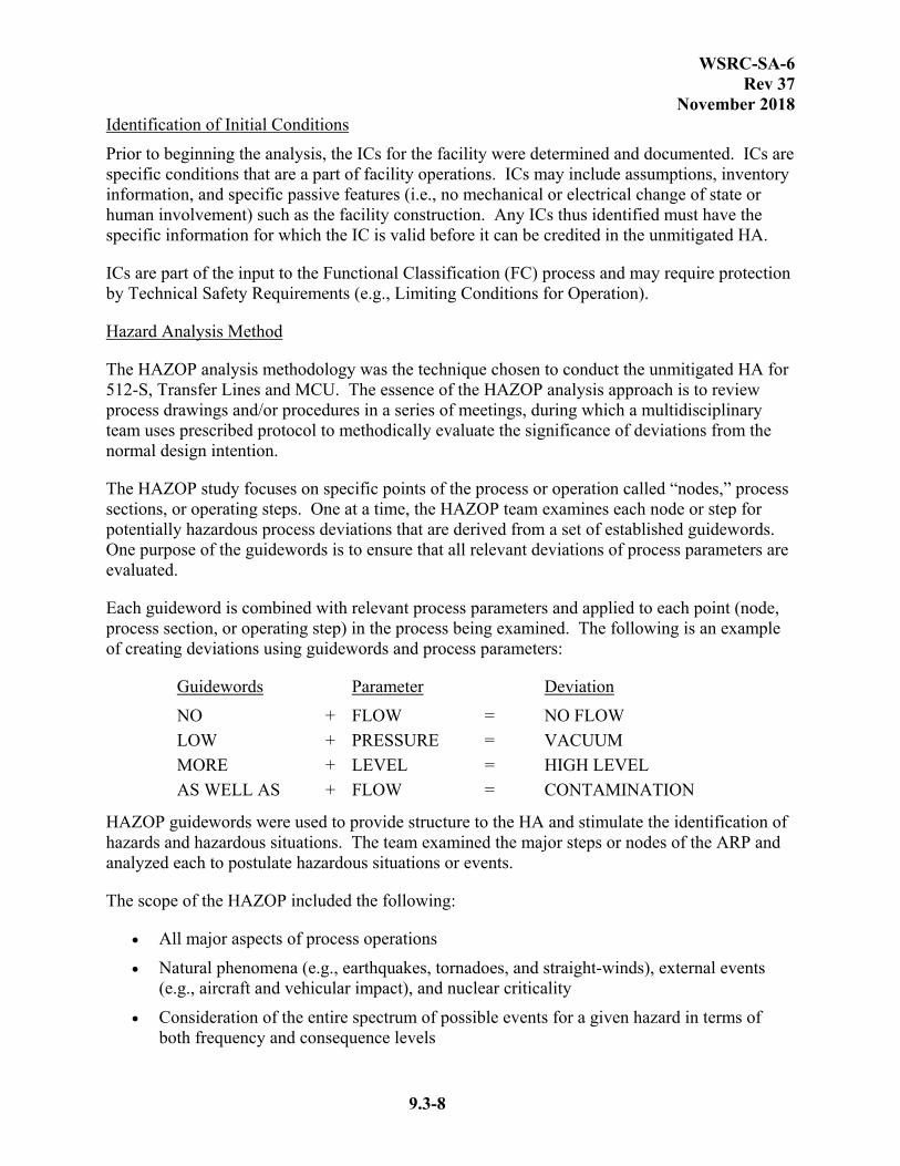
Each guideword is combined with relevant process parameters and applied to each point (node, process section, or operating step) in the process being examined. The following is an example of creating deviations using guidewords and process parameters:
Guidewords Parameter Deviation
NO + FLOW = NO FLOW
LOW + PRESSURE = VACUUM
MORE + LEVEL = HIGH LEVEL
AS WELL AS + FLOW = CONTAMINATION
HAZOP guidewords were used to provide structure to the HA and stimulate the identification of hazards and hazardous situations. The team examined the major steps or nodes of the ARP and analyzed each to postulate hazardous situations or events.
The scope of the HAZOP included the following:
All major aspects of process operations
Natural phenomena (e.g., earthquakes, tornadoes, and straight-winds), external events (e.g., aircraft and vehicular impact), and nuclear criticality
Consideration of the entire spectrum of possible events for a given hazard in terms of both frequency and consequence levels

WSRC-SA-6 Rev 37
November 2018
9.3-9
Facility activities or systems that pose no hazards or only pose common/standard industrial hazards addressed by other programs or regulations (e.g., Occupational Safety and Health Administration [OSHA], Department of Transportation) were examined to the extent only if a loss of control of the activity or system could result in a release.
The What-If Analysis technique is a brainstorming approach in which a group of experienced people familiar with the process being analyzed ask questions or voice concerns about possible undesired events.
The scope of the HAZOP and What-If CHAs did not include hazards screened as common hazards and willful acts, such as sabotage.
Common hazards are defined as materials or energy sources that are routinely encountered in general industry and construction and for which consensus codes and/or standards (e.g., OSHA) exist to guide safe design and operation and are implemented. In accordance with Department of Energy (DOE)-Standard (STD)-3009-94 (Ref. 6), common hazards are typically evaluated only to the extent that they could act as initiators and contributors to events that result in a radiological or chemical release.
Unmitigated Hazard Analysis
The unmitigated HA documents the hazards of the facility, identifies and documents common/standard industrial hazards, identifies and groups unmitigated scenarios, and bins these hazardous events according to risk.
The unmitigated HA was performed using the HAZOP or What-If analysis technique to determine the risks involved with the facility and its associated operations without regard for any safety controls or programs. Unmitigated refers to the determination of the frequency and consequences without credit given for preventive or mitigative features other than the specified ICs. This is essential to avoid taking credit for any types of active or passive barriers or controls that may require some level of configuration control to ensure that the controls remain in place after completion of the HA. Some controls may be designated as SC or SS depending upon which receptor (Offsite or Onsite) consequence or frequency was reduced. During the unmitigated HA, the Material at Risk (MAR) equaled the available hazardous inventory that could be acted upon during the postulated event. No credit was taken for any controls; however, the laws of physics and chemistry were obeyed.
The results of the Hazards Analysis are documented in HA tables. Information contained in these tables typically includes the following:
Event Number
Node
Deviation (except TL and LDB events)
Causes/Results
Unmitigated Frequency

WSRC-SA-6 Rev 37
November 2018
9.3-10
Unmitigated Consequences
Unmitigated Risk Rank
Controls
Notes
Node
The Hazards Analysis study focused on specific points of the process or operation called “nodes.” Each node was examined for potentially hazardous process deviations that are derived from a set of established guidewords.
Deviation
Deviations are departures from the design intention that are discovered by systematically applying the HAZOP guidewords to process parameters (flow, pressure, etc.). The result is a list for the HAZOP team to review (no flow, high pressure, etc.) for each process node.
For the What-If Analysis, the deviations are based on abnormal process parameters identified by the CHAP team members.
Causes
Based on the node and deviation, causes or reasons why the deviation might occur were identified. Once a deviation has been shown to have a credible cause, it can be treated as a meaningful deviation. Causes may be hardware failures, human errors, unanticipated process states (e.g., change of composition), or external disruptions (e.g., loss of chill water). By identifying the cause(s) of the postulated event, the team is able to better determine the initiating frequency and achieve a better understanding of preventive and mitigative features.
Unmitigated Frequency
The unmitigated event frequency was determined through a qualitative and/or semi-quantitative process that involved assigning a frequency level to each event identified that could result in a release of hazardous energy and/or material, personnel injuries, loss of equipment or facilities, or loss of production. Frequency levels and descriptions, as specified in the Consolidated Hazards Analysis Process (CHAP) Program and Methods Manual (Ref. 168, 193, 212, 216, and 221), are outlined in Table 9.3-1.
The team determined which frequency level was appropriate for a particular event based on the event’s cause(s). Sources of frequency information included the following: generic initiator frequency data, existing safety documentation, engineering calculations, generic failure rate data, and facility expert opinion. The frequency level was recorded in the unmitigated HA tables in the Unmitigated Frequency column according to Table 9.3-1.
Erring in the conservative direction from best-estimate values accommodated uncertainties in frequency levels. This practice is particularly important when an event frequency is just below

WSRC-SA-6 Rev 37
November 2018
9.3-11
the next highest frequency level. For example, 9.7E-03 per year is at the high end of the “Unlikely” level. The CHAP team, considering the sources, methods, and uncertainty associated with this value, might collectively decide to call this event frequency “Anticipated” rather than “Unlikely.”
When evaluating event frequency, credit may be taken for items identified as ICs.
Unmitigated Consequences
Based on the node, deviation, and cause, event consequences were determined. Consequences could include a release of hazardous energy and/or material, personnel injuries, loss of equipment or facilities, loss of production, or none. If a consequence was determined to be a common hazard or standard industrial hazard, the event was documented as such.
Event consequences are documented by specifying the impact on the receptors (described below). For HA purposes, unmitigated consequences are defined as the dose or exposure at specified receptor locations that have been determined without taking credit for barriers or controls, which could reduce the consequences. When evaluating event consequences, credit may be taken for items identified as ICs. Consequences are a function of the type and characteristics of the hazard, the quantity released, the release mechanism, relative location of the release, and any relevant transport characteristics. Consequences can be determined from (1) simple Source Term (ST) calculations, (2) existing safety documentation, and/or (3) qualitative assessment supported by back of the envelope calculations. The CHAP team utilized its discretion, expertise, and knowledge of facility hazards to select one or more of the above methods appropriate for consequence determination. In most cases simple calculations were used to estimate doses at 100 m and the site boundary. The team used the 100 m numbers, judgment and the results of shielding calculations to judge the consequence levels for the FW.
Much like frequency evaluation, consequence evaluation is encouraged to err in the conservative direction, especially for those events with consequences at the high end of a given level.
Consequence evaluation is the process of determining which of the consequence levels are relevant to the three receptors for a particular release event. Table 9.3-12 gives the radiological and chemical consequence levels for the specified receptor locations. Receptors are as follows:
Facility Worker FWs are workers immediately adjacent to, or in, the occupied area of the hazard. “Occupied area of the hazard” refers to the area within the last possible means of physically controlling the hazard or controlling access to the hazard (i.e., building, fence, permanent chain with multiple warning signs, etc.). Note: a physical barrier credited to protect workers outside the area or prevent entrance of workers into the area is to be identified as an IC.
Collocated Worker CWs are workers outside the occupied area of the hazard. If there is no defined physical means of controlling the hazard or controlling access to the hazard, the location is assumed to be at the worst possible location, but
WSRC-SA-6 Rev 37
November 2018
9.3-12
no closer than 100 meters to the hazard. For this analysis, CW consequences were qualitatively determined from the dose at 100 meters.
Public Public receptors are the public or everyone outside the site boundary at the time of the event. For this analysis, Public receptor consequences were qualitatively determined from the dose at 10.9 kilometers (Ref. 145). The offsite public may also be referred to as the offsite receptor or the offsite individual.
The unmitigated HA is concerned with the maximally exposed individual at each of the receptor locations.
The unmitigated HA determines the impact (Table 9.3-12 terms: High, Moderate, Low, or Negligible) of the event on the three receptors for each of the postulated release events in the Unmitigated Consequence column. Additionally, information on consequences other than chemical or radiological exposure to individuals is presented in this column. This information may include the physical consequences to the FW (e.g., an explosion that has low radiological and chemical consequences, but could result in a worker fatality), safety impacts in other areas of the facility (e.g., a lightning strike knocks out facility power that, in turn, shuts down the air compressor(s) that disables the air supply of the primary purge system), production loss, or equipment or facility damage.
Using event frequency and consequence levels, events are “binned” in frequency-consequence space to assess relative risk. The objective of risk binning is to focus attention on those events that pose the greatest risk to the Public, CW, and the FW. Higher risk events might be candidates for additional analysis and/or FC evaluation.
Once the team has estimated the unmitigated event frequency and consequence level, events are located on the appropriate Risk Criteria Matrix for the Public, CW, or FW, as shown in Table 9.3-13. The Risk Rank column of the unmitigated HA tables provides the risk rank for each of the three receptor locations. The following risk regions are identified with guidance for control selection:
Region “A1” Unmitigated events in Region “A1” due to radiological release require controls (Safety Class (SC) for public and Safety Significant (SS) for workers), and are highly recommended for additional Levels of Control (LOC) for all receptors per References 132 and 215. Unmitigated events in Region “A1,” due to chemical release or prompt fatality (etc.), require SS controls and are highly recommended for additional LOC per References 132 and 215. DID/ITS controls are identified as part of the control selection process typically after SC or SS controls have been selected. See Appendix 8.16 (Ref. 221) for additional information on DID/ITS. The goal is that the mitigated consequence is moved well into the B region, and possibly the “C” region or the event is prevented.
Region “A2” Unmitigated events in Region “A2” due to radiological release require controls (SC for the public and SS for workers), and are recommended for additional LOC for all receptors per References 132 and 215. Unmitigated events in
WSRC-SA-6 Rev 37
November 2018
9.3-13
Region “A2,” due to chemical release or prompt fatality (etc.), require SS controls and are recommended for additional Levels of Control per References 132 and 215. DID/ITS controls are identified as part of the control selection process typically after SC or SS controls have been selected. See Appendix 8.16 (Ref. 221) for additional information on DID/ITS. The goal is that the mitigated consequence is moved well into the B region, and possibly the “C” region or the event is prevented.
Region “A3” Unmitigated events considered credible per E7, 2.25 falling in Region “A3” due to radiological release require controls (SC for the public and SS for workers), and are considered for additional LOC for CW or public per References 132 and 215. Unmitigated events falling in Region “A3,” due to chemical release or prompt fatality (etc.), require SS controls and consideration for additional LOC per References 132 and 215. DID/ITS controls are identified as part of the control selection process typically after SC or SS controls have been selected. See Appendix 8.16 (Ref. 221) for additional information on DID/ITS. The desired result is that the mitigated consequence is moved into the “B” or “C" region, or the event is prevented.
Region “B1” For unmitigated events having moderate "B1" consequences SC controls should be selected for radiological events affecting the public. Justification must be provided when SC controls are not implemented. DID/ITS controls are identified as part of the control selection process typically after SC or SS controls (if required) have been selected. See Appendix 8.16 (Ref. 221) for additional information on DID/ITS.
Region “B” DID/ITS controls are identified as part of the control selection process typically after SC or SS controls (if required) have been selected. See Appendix 8.16 (Ref. 221) for additional information on DID/ITS.
Region “C” Events falling in Region “C” are not considered for controls.
Controls
Following the identification of hazardous events, the CHAP team identified controls for events requiring SC or SS controls per the guidelines summarized above. For “B” region events, DID/ITS controls were identified. Region “C” events generally have negligible consequences and were not considered for control selection.
Preventive controls are features expected to reduce the frequency of a hazardous event. The identification of such features was made without regard to any possible pedigree of the feature such as procurement level or current classification. These might include engineered features (e.g., SSCs), Administrative Controls (ACs) (e.g., procedures, policies, programs, etc.), natural phenomena (e.g., ambient conditions, buoyancy, gravity, etc.), or inherent features (e.g., physical or chemical properties, location, elevation, etc.) operating individually or in combination.
WSRC-SA-6 Rev 37
November 2018
9.3-14
Mitigative controls are any features expected to reduce the consequences of a hazardous event. The identification of such features was made without regard to any possible pedigree of the feature such as procurement level or current classification. Mitigative features must be capable of withstanding the environment of the event. These might include engineered features (e.g., SSCs), ACs (e.g., procedures, policies, programs, etc.), natural phenomena (e.g., ambient conditions, buoyancy, gravity, etc.), or inherent features (e.g., physical or chemical properties, location, elevation, etc.) operating individually or in combination. Mitigative features constitute a significant portion of DID and worker safety.
DEVELOP CONTROLS
Developing controls begins with the treatment of events requiring SC or SS controls. Controls to be credited are selected from the list of controls initially identified by the CHAP team. Control strategies were chosen using the following preferred selection strategy:
Prevention over mitigation
Passive over active
Engineered controls over ACs
Factors such as cost, reliability, durability, life cycle cost, and facility operating life were also considered during control selection.
Target frequency and consequence reductions are first established. Rules of thumb are then applied to estimate the frequency/consequence reductions and the results compared against targets (i.e., do the controls move the mitigated frequency/consequence well into the “B” or “C” region of the Risk Criteria). Controls are then selected from among those potentially available and credited against the event. This leads to the specification of SC, SS, and DID/ITS controls consistent with the E7 Procedure Manual, Procedures 2.25 and 2.25A (Ref. 132 and 215). Additional scenarios are then postulated by examining control failures, or by identifying new hazards introduced by the controls, with the result that controls may be modified or additional controls added. This step continues to the subsystem and component level as necessary. The list of SC, SS and DID/ITS controls are re-examined and changes made, as necessary.
At this point, the overall system and subsystems are examined along with interfaces to other potentially interfacing systems, and additional controls added, as required. Finally, controls are optimized (e.g., have two or more controls been specified for various scenarios when one control may effectively address all scenarios in the group). Events affecting the Public are forwarded to accident analysts along with a list of candidate Design Basis Accidents (DBAs). In all cases, the evaluation must select controls to ensure that the risk is “well below” the applicable risk criteria before the event is placed into the lower region.
Control development continues by evaluating the “B” region events. The first step is to determine if a control identified during the evaluation of an “A” region event covers a “B” region event as well. Otherwise, the steps for evaluating “B” region events are very similar to the evaluation of “A” region events.

WSRC-SA-6 Rev 37
November 2018
9.3-15
Since “C” region events generally have negligible consequences and are well below the risk criteria, controls were not developed.
The Accident Analysis activity, which is not covered as part of CHAP, determines if SC controls are over- or under-specified and serves as a validation of the controls selected during the mitigated HA/control strategy development activity. The Accident Analysis activity also verifies DBA selection. If SC controls are not validated by the Accident Analysis activity, additional control selection activity will be performed that may lead to a revision of this document.
9.3.2 HAZARD ANALYSIS RESULTS
HA results are provided for both the PHA and the CHA. The PHA HA Results are shown in Section 9.3.2.1. The CHA Results are shown in Section 9.3.2.2 which reports the conclusions for 512-S, the Interarea Transfer Lines, and Confined Hydrogen. The hazards, accidents, and initiators identified for GWSB #1 are applicable for GWSB #2. The consequences for each credible accident are evaluated in Reference 129.
9.3.2.1 PHA Hazard Analysis Results
The PHA results include a listing of the process hazards, a facility hazard classification based on the criteria of DOE-STD-1027-92, and a qualitative evaluation of the hazards identified (Ref. 5 and 14). A complete, detailed listing of the hazards analysis results is presented in WSRC-TR-94-0586 (Ref. 5). This section presents a summary of the results for the LPPP, Vitrification Building, GWSB #1 and FESV. The PHA results, in the form of events identified as potential accidents, provide the starting point for the accident selection described later in this section and the subsequent accident analyses presented in Section 9.4. Qualitative evaluation of the hazards in the PHA allows the subsequent quantitative analysis to focus on the credible accidents that characterize the maximum consequences and overall risk of DWPF operation.
The CHA performed for the MCU and 241-96H integration as well as the inclusion of melter bubbler modifications and potential flammables from retained hydrogen in the vessels and ADPs from antifoam addition is presented in U-CHA-S-00006 (Ref. 169) and the results relating to the LPPP, Vitrification Building, GWSBs and FESV are also discussed in this section.
HAZARD IDENTIFICATION
The detailed results of the hazard identification effort for the DWPF are contained in the completed Hazards Survey Checklists in WSRC-TR-94-0586 (Ref. 5). Section 9.4.2 identifies the hazards that resulted in situations of concern or major concern, according to Figure 9.3-1. Section 9.4.2 identifies specific energy sources under each of the DOE MORT hazard categories listed in Section 9.3.1.1 along with their respective locations. The hazard categories listed in Section 9.4.2 are summarized below and include explosions, fires, mechanical confinement breach, chemical confinement breach, ionizing radiation and toxic pathogenic releases. A comprehensive hazard description is provided in WSRC-TR-94-0586 (Ref. 5) and U-CHA-S-00006 (Ref. 169).

WSRC-SA-6 Rev 37
November 2018
9.3-16
Explosion Hazards
Explosion hazards in the DWPF are associated with several different materials or reactions. All of these hazards can lead to the evolution of a highly flammable gas which, if ignited in a confined space, would lead to a rapid pressure buildup followed by a potential loss of structural integrity.
During operations, several process tanks in the LPPP, Chemical Process Cell (CPC), and Salt Process Cell (SPC) have an explosion hazard present involving primarily hydrogen vapor. Hydrogen gas is evolved through radiolysis of water (organics contribute when present) and thermolysis of process stream constituents in the aqueous solutions stored in the H-Area tanks and during processing of HLW Salt in 512-S and is carried over into the DWPF LPPP and Vitrification Building. Hydrogen is also produced by the destruction of formic acid in several vessels in the CPC.
Hydrogen presents an explosion hazard in the CPC primarily from the destruction of formic acid (radiolysis contributes to a lesser degree) in the Sludge Receipt and Adjustment Tank (SRAT), Slurry Mix Evaporator (SME), and Melter Feed Tank (MFT). The Slurry Mix Evaporator Condensate Tank (SMECT) can contain formic acid and radioactive material when an overflow or carry over from the SME or SRAT occurs. The Recycle Collection Tank (RCT) and Decontamination Waste Treatment Tank (DWTT) can contain formic acid and radioactive material. SRAT and SME reactions also produce NO and NO2, which are both strong oxidizers and can support combustion. These vapors can be present in the vessels themselves or outside as a result of leakage or breach.
If agitation is stopped, the waste in the vessels can potentially retain generated hydrogen, which can then be released when agitation restarts, exceeding the vapor space flammability. The vessels that have the potential to retain significant hydrogen in the waste include the SRAT, the SME, the MFT, and the LPPP Sludge Pump Tank (SPT) (Ref. 169 and 213).
An additional organic concern exists with the organic solvent mixture that can be carried over from MCU with the Strip Effluent. The BOBCalix-based solvent is a mixture of approximately 70 wt% Isopar L, 30 wt% modifier (Cs-7SB) and other minor components (Trioctylamine and BOBCalixC6). The Next Generation Solvent (NGS) is a mixture of approximately 74 wt.% Isopar L, 20 wt.% Cs-7SB, 6 wt.% MaxCalix, and a fourth minor component, TiDG (a guanidine derivative). Isopar L is a mixture of branched–chain hydrocarbons that is used as the diluent in the CSSX solvent and can be represented by C11H24, having a flashpoint of 61 ºC (Ref. 172). The modifier has a low vapor pressure with flashpoint greater than 300ºC (Ref. 172). Although the solvents contain other organics, Isopar L is the only flammable component of concern from the MCU solvent that presents an explosion or fire hazard upstream of the Melter due to the concentrations, vapor pressures, and high flashpoints of the other solvent components (Ref. 172 and 203). Isopar L could be contained within the SRAT off-gas system downstream of the SRAT. However, due to the controls to limit the amount of Isopar L (Ref. 174) and the safety significant purge, condensation is prevented in the SRAT condenser train (SRAT condenser, SRAT ammonia scrubber and FAVC). This prevents Isopar L via the condensate from entering the vessels downstream of the SRAT (MWWT, SMECT, RCT and RPT). The calculation for the maximum organic feed to prevent condensation in the condenser train (Ref. 174) was evaluated

WSRC-SA-6 Rev 37
November 2018
9.3-17
for the higher concentration of Isopar L (approximately 74 wt.%) in NGS. Due to the high calculated value of solvent carryover (239 ppm, Ref. 174) that is allowable without condensing in the condenser train, and no changes to the Isopar L concentration limit of 87 mg/L, it was determined that with the slight increase in Isopar L wt.% for NGS (results in a slightly lower maximum solvent concentration in the feed), the SRAT purge remains adequate and condensation would not occur when processing SE containing NGS.
Isopar L can form organic layers in static process vessels or outside as a result of leakage or breach. The organic will evaporate at the liquid surface and diffuse into the tank vapor space driven by thermal gradients within the tank and contribute to the flammable gas mixture causing a bulk vapor space explosion. If a thermal gradient is not present, the heavy organic will evaporate and remain immediately above the liquid in the tank forming a high organic vapor layer concentration. If the liquid temperature is above the flashpoint of 61 ºC, an electric spark is sufficient to ignite the organic vapor layer of Isopar L causing an explosion at the liquid/vapor interface. At temperatures below the flashpoint, a sustained ignition source is required to ignite the organic vapor layer. Releases from an organic vapor layer explosion are limited to the volume of the layer formed at the liquid/vapor interface and is bounded by the bulk vapor space explosion.
The degradation products of antifoam are also flammable organics of concern. Antifoam is routinely added to the SRAT and SME to minimize foaming and possible carryovers to the SMECT while processing. The ADPs (hexamethyldisiloxane (HMDSO), trimethylsilanol (TMS), and propanal) have been identified as flammable hazards.. The amount of ADPs released into the vessel vapor space is related to several variables, including: volume of antifoam added, conditions (e.g., pH, temperature) in the receiving vessel at the time of addition, and frequency of addition. Therefore, impacts of the ADPs on the vessel flammability can be limited by managing these variables. The ADPs are potentially present in the SRAT (direct addition of antifoam), the SME (direct addition of antifoam), the SMECT (carryover from SRAT or SME), the MFT (transfer from SME), the RCT (transfer from SMECT or cell sumps containing leakage), and the RPT (transfer from RCT). Therefore, the ADPs are taken into consideration in the CPC and LPPP vessel explosion evaluations as well as the cell explosions due to vessel leakage or breach.
An explosion could also occur in the melter off-gas system if flammable gases produced in the melter are not diluted sufficiently by the melter purge gas.
An explosion hazard also exists in the form of pressure-volume combinations. Several pieces of equipment operate under high pressure, such as the portable mercury pumps. Steam under pressure creates the pressure-volume explosion hazard in several different locations, and cooling water under pressure can also be considered to present the hazard.
The possibility of an interaction of water with molten salt gall (salt anions at concentrations greater than their solubility in glass), leading to overpressurization of the melter, is also a pressure-volume explosion hazard. The possibility of a steam explosion is present in the melter vessel because high-water-content transfers are routinely received there, and the contents of the melter are normally maintained around 1,100 °C. If the viscosity of the molten glass in the
WSRC-SA-6 Rev 37
November 2018
9.3-18
melter is lowered significantly, water transferred to the melter could mix with the molten glass and cause a steam explosion.
Explosive energy in the transfer line core pipe or jacket comes from the buildup of hydrogen gas. Hydrogen gas is assumed to be present due to the accumulation of waste in either the jacket or core pipe. Explosive energy can also come from the buildup of flammable organic vapors within the transfer line core or jacket. One source of organic comes from the solvent carried over into the MCU Strip Effluent from the CSSX process. As previously mentioned, this solvent may also be present in the Recycle stream, which is transferred from the RCT to the Tank Farms via the RPT. The organics from antifoam degradation can also be present in the Recycle stream. The specifics of the Transfer Line Core and Jacket Explosion events are provided in the DWPF CHA (Ref. 169).
An explosion is possible in non-safety related pipes or components that are exposed to hydrogen generation, but are not properly vented to prevent the formation of an explosive atmosphere (i.e., confined hydrogen sources/locations). Some piping and components may fragment or whip if such an explosion occurs. The fragments or whipping pipe may contact and cause failure of safety related equipment (Ref. 179).
Fire Hazards
Fire energy source hazards are separated into three categories: (1) flammable/combustible materials; (2) electrical; and (3) hot equipment/thermal radiation. The items in the DWPF discussed below were documented in the Hazards Survey Checklists in the PHA (Ref. 5) and DWPF CHA (Ref. 169).
The flammable/combustible material hazard category includes any material that will support combustion or burn readily. With respect to the 221-S Vitrification Building, ammonium nitrate/high boiler organic deposits could be contained within the Process Vessel Vent Header (PVVH) downstream of the SRAT, the RCT, and the SMECT.
The organic solvent carried over into the MCU Strip Effluent from the CSSX process can separate out of solution, if left undisturbed for a period of time, leading to the de-entrainment of an organic layer on the surface of the liquid. The organic solvent contains Isopar L, which can be represented by C11H24, having a flashpoint of 61 ºC. If the temperature of the liquid is above the flashpoint of 61 0C, an electric spark is sufficient to ignite the floating layer of organic causing a pool fire. At temperatures below the flashpoint, a sustained ignition source is required to burn the floating organic layer of Isopar L. The ADPs do not contribute to the organic pool fire (Ref. 169).
Other flammable materials listed in the Hazards Survey Checklists include the following:
Hydraulic oil
Grease
Paints
Various transient combustible materials (e.g., plastic, cardboard, and cloth materials)

WSRC-SA-6 Rev 37
November 2018
9.3-19
Acetylene
Propane gas cylinders
Power, control, and instrumentation cable located in open cable trays
Diesel fuel
Hydraulic fluid
Rubber tires
Lead acid batteries
These hazards were not considered significant (i.e., they did not pass the qualitative screening criteria for inclusion in the hazard evaluation summary table), but the specific hazard sources and locations are identified in WSRC-TR-94-0586 (Ref. 5).
In terms of electrical fire hazards, electrical cable located within the process cells and in open cable trays throughout the remainder of the building can be considered as a flammable/combustible material.
The hot equipment/thermal radiation category includes any equipment that may reach temperatures high enough to initiate a fire, cause personal injury, or result in a radioactive and/or chemical release. For the DWPF, the only significant thermal radiation hazard identified was the melter vessel electrodes.
Other thermal radiation hazards discussed in WSRC-TR-94-0586 include the following (Ref. 5):
MCCs, transformers, power panels located in the Electrical Rooms, and other power distribution equipment that could become hot enough to initiate a fire if not properly ventilated and if combustibles are situated nearby
Other hot equipment/thermal radiation sources, such as the filled waste canisters, steam generators and distribution lines, plug welder, and small ovens/furnaces used in the Mezzanine Level Analytical Laboratory
Diesel generators, chemical waste tank surfaces during the neutralization process, portable welding machines, and other operating equipment located in the DWPF
Complete assessments and analyses of fire events in the DWPF can be found in the FHAs for the DWPF (Ref. 22, 24, 25, 26, 28a, and 28b).
Mechanical Confinement Breach Hazards
Mechanical confinement breach hazards related to DWPF operations encompass gravitational potential energy, translational KE, and rotational KE sources. Significant hazards identified by the DWPF PHA (Ref. 5) and DWPF CHA (Ref. 169) include overhead traveling bridge cranes, overhead monorail hoists, transfer and sump pump motors, and multiple speed agitators. Other potential mechanical confinement breach hazard sources are also discussed in the PHA (Ref. 5) and DWPF CHA (Ref. 169).
WSRC-SA-6 Rev 37
November 2018
9.3-20
Chemical Confinement Breach Hazards
There are two types of chemical confinement breach hazards: the corrosive hazard and the chemical interaction hazard. Several of the chemicals present in the DWPF during operation of the process or during storage between batches can present either a corrosion or a chemical interaction hazard, or both. Corrosive energy source hazards exist in the oxalic acid and nitric acid decontamination feed tanks and their piping systems.
Although the radiological hazard presented by the contents of the process vessels in the CPC is of far more concern, the formic and nitric acids contained therein are corrosive hazards as well. Water and steam at normal (atmospheric) and elevated pressures, in several locations, can be considered a corrosive hazard.
Chemical interaction between nitric acid (HNO3) and formic acid (HCOOH) or interaction of sodium nitrite (NaNO2) and acids, results in the creation of NO and NO2, which are both strong oxidizers. In addition, incorrect spool piece connections during maintenance operations can lead to other chemical interactions between incompatible substances, such as HNO3 and sodium hydroxide (NaOH).
Further analysis was performed on the chemical hazards identified in the PHA (Ref. 183). The consequences from pure chemical releases, as well as from chemical reactions, that were not directly related to radiological processes have been determined to be SIHs. It is not the intent of the DSA to cover safety as it relates to the common industrial hazards in which national consensus codes and/or standards (e.g., Occupational Safety and Health Administration [OSHA] regulations) already define and regulate appropriate practices without the need for special analysis. The DWPF is designed to handle Standard Industrial Chemical Hazards as described in Reference 183 which specifies various consensus standards for chemical hazards, storage tanks, chemical process components, etc. regardless of functional classification (i.e., a non-SC or non-SS chemical storage tank would stall have to meet these code requirements).
Ionizing Radiation Hazards
The primary source of ionizing radiation associated with DWPF operations are the sludge, MST/Sludge Solids and Strip Effluent contained within the Vitrification Building CPC, SPC, Melter Vessel and the LPPP tanks. The filled waste canisters, located in the Melter Cell, Canister Decontamination Cell (CDC), Smear Test Station, Weld Test Cell (WTC), Shielded Canister Transporter (SCT), and GWSBs represent the other major source of ionizing radiation. In addition, contaminated failed process equipment that will be handled in the Vitrification Building Remote Equipment Decontamination Cell (REDC), Contact Decontamination and Maintenance Cell (CDMC), Railroad Well and Airlock, and FESV Facility, is also listed under this category.
Toxic-Pathogenic Hazards
Energy source hazards under this category include toxic vapors resulting from DWPF operations. These hazards include toxic vapors from the cold chemical feed systems such as formic acid and mercury; and the toxic chemicals used in the Vitrification Building Analytical Laboratory.

WSRC-SA-6 Rev 37
November 2018
9.3-21
Additionally, those compressed gases (i.e., argon, halon 1301) that are used throughout the DWPF are listed under the toxic-pathogenic category.
Radiological/Chemical Inventories
The DWPF radiological and chemical inventories documented in the Hazards Survey Checklists in WSRC-TR-94-0586 (Ref. 5), WSRC-TR-2002-00223 (Ref. 120), and U-CHA-S-00006 (Ref. 169) are considered ionizing radiation and toxic pathogenic energy source hazards. These inventories were analyzed in relation to the identified energy source hazards documented in the Hazards Survey Checklists (i.e., MORT hazard category energy sources) in order to postulate those accident scenarios in which these radiological and chemical inventories would be released.
HAZARD CLASSIFICATION
The identification and documentation of hazardous materials during the facility walk downs leads directly to the preliminary hazard categorization per DOE-STD-1027-92 (Ref. 14). For radiological hazards, hazard categorization is an essential tool in determining if a Safety Analysis Report (SAR) is required in accordance with DOE Order 5480.23 (Ref. 12). If required, the facility hazard category is used in applying a graded approach to the level of detail required in the SAR. Chemical hazards are discussed separately in DOE-STD-1027-92 (Ref. 14).
DOE-STD-1027-92 (Ref. 14) permits the technique of facility segmentation for the assessment of hazards to avoid placing excessive requirements on simple collocated operations. Segmentation is allowed provided the hazardous material in one segment cannot interact with hazardous material in other segments (Ref. 12). Therefore, in accordance with DOE guidance, the DWPF can be segmented as listed in Table 9.3-4 and as described in WSRC-TR-94-0586 (Ref. 5). Additionally, the 512-S was classified as a Category 2 (Ref. 120) and Glass Waste Storage Building #2 as a Category 2 facility as described below.
Glass Waste Storage Building #2, though not mentioned in the DWPF PHA (Ref. 5), is similar in construction to the GWSB #1 (Ref. 167). The accident scenarios and initiators are applicable for both GWSBs. The consequences for each credible accident are evaluated in Reference 129.
The final hazard categorization for DWPF resulted in a facility-wide hazard category of 2 (Ref. 5).
HAZARD EVALUATION
In accordance with the hazard evaluation guidance previously discussed in Section 9.3.1, an estimate of the hazard frequency and severity was formulated. This largely qualitative evaluation was documented in the Hazards Survey Checklists contained in WSRC-TR-94-0586 (Ref. 5) and U-CHA-S-00006 (Ref. 169). Information presented in these documents was then considered from several perspectives to more thoroughly assess the safety of DWPF operations.
Defense in Depth Evaluation (DIDE)
A systematic review of the PHA for the DWPF was performed to identify the potential accidents that could result in moderate or high radiological or chemical consequence to the facility worker,
WSRC-SA-6 Rev 37
November 2018
9.3-22
onsite receptor, or to the offsite public (Ref. 5). Evaluation of these accidents was performed by a team of individuals familiar with the operating characteristics of the facilities to determine the existing SSCs that can be used to prevent or mitigate the consequences of the events. The results of this DIDE analysis are presented in WSRC-TR-94-0597 (Ref. 2).
Each of the identified hazards was screened based on consequence type and severity. Those hazards selected for further consideration in the DIDE were then examined with respect to available Mitigative and Preventive Functions (MPFs). MPFs are considered to be SSCs or administrative controls (operator action, operation procedure, facility emergency plans, and maintenance/inspection/testing activities) that serve as barriers against the release of radiologically or chemically hazardous material beyond the normal confinement. The identified MPFs were categorized according to availability type; i.e., those present during normal operation and those available on a post-event basis. MPFs of both types were evaluated to identify the number of Lines of Defense (LODs) available for protection.
Defense-in-depth is provided at the DWPF through utilization of multiple confinement barriers and systems that restrict releases of radioactive material or hazardous chemicals to the environment or into areas normally occupied by plant personnel. For radioactive materials, the methods of confinement depend on the mobility, quantity, type, and intensity of the radioactive material and its effect on the ecosystem. The first confinement barriers are commonly the walls of process vessels, piping, and product containers. Additional barriers, as necessary, are provided by ventilation systems, process cell walls, or building walls. These additional barriers serve to limit the spread of airborne contamination that could arise from leakage of either gases or liquids from process and storage vessels into cell air spaces and ultimately into other areas. For the DWPF analysis, a decontamination factor of 200 is assumed for the Zone 1 ventilation sand filter based on the 97% bounding value (the value exceeded 97% of the time) observed during these filtration studies (Ref. 67). Barriers are also used to prevent the spread of contamination via leakage of contaminated liquids and solids.
Confinement of hazardous chemicals in the Vitrification Building is generally accomplished using the confinement barriers and ventilation systems installed to confine radioactive materials within the process cells and to prevent personnel exposure in the operating areas of the building. Additional confinement features include spill dikes around all tanks. Permanent spill dikes are constructed of concrete and coated with sealant to prevent migration of hazardous chemicals into the surrounding soil.
The DWPF CHA (Ref. 169) provides the defense-in-depth analysis for the hazards.
Safety Significant Structures, Systems and Components
As described above, LODs are defined as part of the DIDE analysis for the hazards, which are considered to be significant based on consequence type and severity. For each accident that has the potential for unacceptable consequences to facility workers, SS SSCs are defined based upon a review of the identified LODs. The overall process for identification of SS SSCs is described in References 4, 120 and 169. Table 9.3-10, Table 9.3-11 and Section 4.4 identifies the SS SSCs.

WSRC-SA-6 Rev 37
November 2018
9.3-23
Non-Safety Related Structures, Systems and Components – Interaction Sources
A number of SSCs, i.e., piping, jumpers, tubing, instruments, and other piping system components, were identified as having the potential for accumulating hydrogen due to the un-vented vapor spaces that could exist in them (i.e., confined hydrogen sources/locations). Explosions in these components could cause fragmentation or whip of the component such that safety related components could be impacted and lose their capability to perform their safety function(s). Such interactions were evaluated in a Confined Hydrogen CHA (Ref. 179).
Technical Safety Requirements
The SS SSCs and the administrative controls identified in Table 9.3-10, Table 9.3-11 and Section 4.4 are the basis for specification of TSRs to address defense-in-depth and worker safety considerations. A detailed discussion of the requirements applicable for DWPF is included in Chapter 11.
Worker Safety
This section summarizes the efforts for identification of SS SSCs and major features protecting workers from the hazards of facility operation.
Identification of Safety Significant Structures, Systems and Components Related to Worker Safety
The DIDE analysis and the identification of SS SSCs and TSR controls addressed hazards that have the potential to impact site workers. This includes site workers in the immediate area of the hazard and site workers that are located outside the physical area containing the hazard. The SS SSCs and the administrative controls identified in Table 9.3-10, Table 9.3-11 and Section 4.4 are the basis for specification of TSRs to address defense-in-depth and worker safety considerations. A detailed discussion of the TSRs applicable for the DWPF is included in Chapter 11.
Worker Safety Programs
The major DWPF safety programs are documented in Chapter 8 and Chapter 10. Worker safety design features are addressed in Chapter 4. These chapters discuss in detail the operational safety provisions in place at the DWPF and the major preventive and mitigative features protecting workers from the hazards documented in the Hazards Survey Checklists in the PHA (Ref. 5); CHA for 512-S (Ref. 120); and DWPF CHA, which includes MCU/241-96H/ARP integration (Ref. 169). Summaries of relevant protection programs follow.
Radiological Protection Program
The DWPF Radiological Control & Health Physics (RP) program, summarized in Section 8.1 of this SAR, is the responsibility of the Radiological Safety and Health Manager. The general responsibilities of RP personnel at DWPF include the following:
Ensure that radiological operations of the facility are conducted in accordance with plant policies and procedures.
WSRC-SA-6 Rev 37
November 2018
9.3-24
Provide information and advice concerning effective radiological protection.
Maintain records to assist in the general program to maintain personnel exposure As Low As Reasonably Achievable (ALARA).
Generic job descriptions and responsibilities for the various RC&HP positions are described in Manual 5Q (Ref. 35).
Based on the estimated annual exposure for operations, maintenance, and other non-administrative personnel and on the projected non-administrative staffing levels for DWPF, the anticipated radiological exposure to the worker is less than the allowable DOE limit as defined in Manual 5Q (Ref. 35).
Industrial Hygiene Program
Industrial Hygiene (IH) hazards include excessive noise, heat stress, oxygen deficiency, equipment ergonomics (e.g., video terminal eyestrain), and toxic chemical exposure. Also included in this category are biohazards associated with process effluents and air conditioning systems. Section 8.2 of this FSAR discusses the DWPF IH program in detail. An estimation of IH injury rates for the DWPF is provided.
Historical experience at F-Canyon was used to assess the potential IH hazards at the DWPF. Activities supporting the cold chemical transfer and makeup within F-Canyon comprise the major IH hazard to personnel. Contact with chemicals or vapor or inhalation of fumes can result in injury. It is estimated that IH injuries at the DWPF would occur with a frequency of
2.1 x 10⁻⁵ injuries/person-hr for operation/maintenance activities (Ref. 36). The IH injury rates
for DWPF laboratory operations are estimated to occur with a frequency of 1.3 x 10⁻⁵ injuries/person-hr (Ref. 36).
Industrial Safety Program
Section 8.3 of this FSAR discusses the DWPF industrial safety program in detail; an estimation of DWPF industrial injury rates is provided below.
Although a DWPF operating history was not available for estimating industrial injury rates, other SRS facilities have an extensive operational history. For evaluating DWPF industrial hazards, the records for F-Canyon, a similar radiochemical processing facility, were reviewed for the years 1984 through 1988. This was considered a good time frame to base DWPF injury rates on because this was a peak production period for F-Canyon. This review produced a representative distribution of different types of injuries.
Maintenance activities performed by personnel using manual tools and equipment were identified as major contributors to minor injury in the workplace. The minor injuries that occurred during these maintenance activities included scratches/cuts, broken skin, abrasions/bruises, broken bones, and skin punctures. The injuries occurred site-wide and were not specific to any individual room or location, nor were they representative of any specific type of proceduralized activity. Skilled craftsmen, doing work for which they are trained and

WSRC-SA-6 Rev 37
November 2018
9.3-25
qualified, occasionally experience minor injuries. Based on data from F-Canyon, it is estimated
that industrial injuries at the DWPF would occur with a frequency of 1.3 x 10⁻⁴
injuries/person-hr (Ref. 36).
Fire Safety Program
The Fire Protection Program, Manual 2Q, establishes the requirements for fire safety. The DWPF Fire Control Preplan, Manual 2Q2-4-S has been established in accordance with Manual 2Q to identify and locate both active and passive fire protection features in each facility and to provide information necessary for proper emergency response in the event of fire. This is accomplished through various organizations, administrative program, and procedures for both passive and active systems. This plan is a comprehensive, integrated approach to minimize both the probability and consequences of fire (Ref. 39 and 40). The Savannah River Remediation Fire Protection Program Plan (F-PRP-G-00001) (Ref. 218) has been developed to implement the Manual 2Q Fire Protection Manual and contains the specific Fire Protection requirements for Savannah River Remediation including assessment frequencies.
The organizational interfaces and responsibilities, and administrative controls that comprise the DWPF Fire Protection Plan are summarized in Section 8.4 of this FSAR, while plant fire protection features are discussed in Section 5.4.10.
Environmental Protection
Measures have been established to ensure confinement of the hazardous materials present during the DWPF process. Through consideration of the potential release pathways and the design and operation features that reduce the potential for large, uncontrolled releases, it is concluded that an appropriate level of environmental protection is ensured for the DWPF. The waste confinement and management functions described in this section cover the significant effluents and byproducts, radioactive and nonradioactive, that are either released to the environment, recovered and managed, or disposed of onsite. Emphasis is given to the potential hazards and features included to ensure safety and environmental protection.
Radiological Gaseous Effluents
As a design objective, the quantities of the contaminants released are to be ALARA and within the applicable limits of the DOE Orders and state and federal laws and regulations.
In the SRAT and SME Lower Flammability Limit (LFL) detectors are employed to detect explosive conditions so that preventive measures may be taken. These measures provide protection from impact to the environment from release through explosion. Primary confinement barriers include the walls of process barriers, piping, and product containers. Under normal operating conditions pressure in the process vessels is slightly negative with respect to that in the process cells. In the event of a breach, gaseous effluent is expected to flow from Zone 1 ventilation to the PVV.
Gaseous effluents and ventilation air from the melter, process vessels, and process cells are contaminated with radioactivity of process origin. These gases are treated by being passed
WSRC-SA-6 Rev 37
November 2018
9.3-26
through a sand filter. This ensures that the concentration of radionuclides is at acceptably low levels before it is discharged to the atmosphere through the stack. Air exhaust from Zone 2 areas, the Weld Test Cell (WTC), and the regulated shops is potentially contaminated with radioactivity as well. Exhaust air from each of these areas is pretreated to the extent needed to isolate the radioactivity source and to avoid cross-contamination. After the initial pretreatment, if needed, the area exhausts are discharged into a single exhaust stream. This stream is processed through a common High Efficiency Particulate Air (HEPA) filtration unit to remove radioactive particulates before it is discharged to the atmosphere through a stack located on the Vitrification Building (Building 221-S) roof.
Gaseous releases from the LPPP and 512-S under normal and abnormal conditions are processed through HEPA filtration using the same defense-in-depth to reduce the potential for radioactive releases to the environment. Nitrogen purge reduces the likelihood of combustion of the flammable materials. Continuous ventilation of the tanks, process cells, and facilities with concurrent, routine sampling for particulates and HEPA filter treatment of each effluent stream, reduces potential impact to the environment.
Once the solid waste has been formed into the glass product and solidified in the stainless steel canisters, environmental protection is provided by the same mechanisms that make the final glass product advantageous in the first place. The waste glass form is not easily released to the environment as liquid or vapor. Even if rupture or breach of the stainless steel canister occurs, the glass form of the waste provides for containment and rapid cleanup from a limited area of exposure. Canisters of glass are stored in the GWSBs. Radioactive decay heat from the canisters is removed by the natural circulation of air and the exhaust air discharges to the atmosphere.
Radiological Liquid Effluents
No liquids of process origin are released to any effluent stream from the DWPF without first passing a radiological screening. Aqueous process liquids are collected, treated, and returned to the H-Area Tank Farm. Releases of chemicals to the environment are minimized as much as possible and maintained within the limits of the South Carolina Department of Health and Environmental Control (SCDHEC) permits.
Sludge, Strip Effluent solution and MST/Salt Solution streams enter the DWPF through a system of interarea transfer lines. The lines are designed and constructed to withstand corrosion and seismic event. Double-walled construction provides additional containment and, with leak detection devices, a method for prompt leak detection to mitigate or prevent impact to the environment. Buried underground lines are provided with warning signs to prevent inadvertent rupture during excavation.
A liquid byproduct, mercury, is generated at the DWPF. Mercury is recovered from DWPF feed slurries during the preparation of slurry feed for the melter. Recovered mercury is transferred to the mercury purification cell and treated to remove impurities and radioactive contamination.
WSRC-SA-6 Rev 37
November 2018
9.3-27
Radiological Solid Waste
Solid waste is controlled at the source of generation to reduce or eliminate it wherever possible. It is treated according to the type of contamination involved as described in Chapter 7.
Nonradiological Waste
The operation of the DWPF generates quantities of nonradioactive liquid, gaseous, and solid wastes. Gaseous effluents from the Cold Chemical Feed distribution systems are filtered prior to being discharged to the atmosphere, as determined by the Industrial Hygiene Program. A single ventilation system is provided to direct discharge of chemical vapors through high efficiency filters to an elevated exhaust located on the Building 221-S roof near the Zone 2 stack. Protection of the environment from large leaks or piping ruptures is provided by the dikes constructed around each tank (or set of tanks holding similar liquids). These dikes are designed to hold the contents of the surrounded tank(s), such that complete tank rupture or spillage of the entire contents will not impact the environment.
The 980-S Chemical Waste Treatment Facility and 422-S Cold Chemical Feed Storage Facility were identified as SIHs. These facilities are governed by applicable codes and standards which require similar controls to those in 221-S.
Two tank ventilation systems are provided in 422-S outside facilities to direct the discharge of chemical vapors and particulates to the environment. The high-efficiency filter removes most particles generated in the charging chute prior to discharge to the outside environment.
The 980-S Chemical Waste Neutralization Facility provides for the neutralization and permitted disposal of nonradioactive chemical and industrial liquid wastes from the DWPF. The chemical waste neutralization system tanks vent to the atmosphere. The organic neutralization tanks are provided with flame arrestors in their vent lines.
Facilities at the 980-S Building are provided to treat batches of chemically contaminated waste water before discharge to the environment. Hold tanks are provided for the caustic and various acid wastes. Chemical agents are added to neutralize the waste before discharge. The floors of the treatment system areas are diked to isolate the chemically contaminated wastewater from each system. The hold tank and neutralization tank overflow lines are sealed to prevent vapor releases through the overflow lines. The design of the tanks to prevent breach from corrosion, seismic action, or other causes, coupled with the dikes are the controls that provide safety and environmental protection.
Accident Selection
In accordance with the hazard evaluation guidance previously discussed in Section 9.3.1, qualitative estimates of the frequency and consequence severities for each postulated accident scenario (or accident class) were formulated. Each postulated accident class can be ranked and grouped (or binned) as to its respective frequency and onsite/offsite consequence severity using the DOE-STD-3009-94 three-by-three frequency and consequence ranking matrix illustrated in Figure 9.3-1 (Ref. 6). As stated in Section 9.3.1, accident binning for this PHA effort was

WSRC-SA-6 Rev 37
November 2018
9.3-28
primarily based on offsite consequences, since these types of postulated accidents are the principal concern detailed in the accident analyses.
Situations of lesser concern are the postulated accident classes that are binned within regions 1 through 4 of the Figure 9.3-1 ranking matrix. These accident classes range from low consequences and unlikely frequencies to moderate consequences and extremely unlikely frequencies. These postulated accidents are considered situations of lesser concern and can be eliminated from further consideration.
Situations of concern include postulated accident classes that are binned within regions 5 and 6 of the matrix based on estimated offsite consequences. These are considered moderate risk accidents that warrant further detailed quantitative accident analyses. These classes deal with accident scenarios involving explosions, over-pressurizations, fires, mechanical confinement breaches, and chemical confinement breaches. The remaining postulated accident scenarios are ranked within region five of the matrix (i.e., moderate offsite consequences and unlikely frequencies). These accident classes deal with scenarios involving explosions or fires.
Situations of major concern are accident classes that are binned within regions 7, 8, and 9 of the matrix with respect to the offsite receptor. These are considered high risk accidents that warrant further detailed quantitative accident analyses. One postulated accident class involves a fire scenario due to ammonium nitrate/high boiler organic deposits in the PVVH. One postulated accident class deals with a scenario involving mechanical confinement breaches resulting from a failure of the 117-ton main process cell bridge crane in the Vitrification Building Canyon.
Due to the potential interactions between energy sources, stored inventory, material processing inventory, and chemical inventories present in the facilities, the hazards survey effort for the DWPF resulted in the identification of potentially high and moderate risk accident classes from which various accident progression scenarios can be postulated. Based on the estimation of offsite consequences and frequencies of these accident classes and subsequent hazard evaluation binning, the high and moderate risk accidents, listed in Section 9.4.2, are considered in the detailed quantitative accident analyses presented in Section 9.4.
As previously stated, natural phenomena accident classes (i.e., earthquake, tornado), although not specifically addressed by the PHA, are considered high risk accidents based upon the radiological and chemical inventories that will be present at the DWPF. Seismic and high wind events are explicitly considered in the detailed accident analyses presented in Section 9.4.
9.3.2.2 Consolidated Hazard Analysis Hazard Results
The CHAP was used to identify potential hazardous events applicable to the ARP at 512-S, the DWPF TLs, MCU/241-96H/ARP integration, retained hydrogen in vessels, ADPs from antifoam additions, the potential for confined hydrogen, and melter bubbler modifications to select potential control strategies that eliminate the hazards and resultant hazardous situations, reduce the likelihood of occurrence of the event, or mitigate the consequences of the event. The CHAP includes a listing of the process hazards, a facility hazard classification, a qualitative evaluation of the hazards identified, and a hazard classification based upon the criteria of DOE-STD-1027-92 (Ref. 14).

WSRC-SA-6 Rev 37
November 2018
9.3-29
This section presents a summary of the results of the 512-S CHA and DWPF CHA. The CHAs performed to address the potential for confined hydrogen, REDC cleaning and process enhancements, interim canister storage double stack, and LWPT and LWHT sampling process were limited scope evaluations. These evaluations were performed using methodologies similar to that performed for the CHAs described below. These CHAs did not result in any new accidents not previously evaluated. No further discussion of the results of these CHAs is provided.
The CHAP consists of the following three basic analytical activities: define the scope of work, HA, and control selection. This section provides a discussion of the results from the performance of these activities for ARP.
DEFINE SCOPE OF WORK
The scope of the 512-S CHA (Ref. 120) only includes the 512-S facility. Although the 512-S interfaces with the LPPP, the LPPP was not included in this HA; nor was the DWPF Vitrification Building. The 512-S does not introduce any new hazard to the LPPP or Vitrification Building. The ARP MST/Sludge Solids are bound by the sludge previously analyzed in the LPPP-SPT and the SRAT in the Vitrification Building. As such, the existing PHA adequately analyzes these areas with sludge bounding the MST/Sludge Solids.
A separate CHA was performed for the modifications and hazards associated with the integration of MCU, 241-96H and ARP waste streams into the DWPF as well as the flammable hazards due to retained hydrogen and organics from antifoam additions (Ref. 169). The CHA re-evaluated the Interarea Transfer Lines, following the same methodology and binning used in the previous CHA. The CHA also re-evaluated the LPPP, Vitrification Building, FESV and GWSBs for additional hazards using the HAZOP and What-If Analysis techniques. The CHA was performed using Reference 215. In Section 9.4 the Functional Classification methodology used is referenced in the individual design basis accidents.
Facility Hazard Category
The objective of facility hazard categorization is to evaluate the potential radiological and chemical hazards associated with 512-S to determine its proper hazard categorization. The focus of hazard categorization is to determine the safety and health documents required for the 512-S facility. Hazard Categorization was developed in accordance with the guidance provided in Code of Federal Regulations (CFR) 10 CFR 830 and the 11Q Manual (Ref. 146 and 148).
The radiological inventory that can be physically released from the facility (Ref. 120) was compared against the Threshold Quantities (TQs) identified in DOE-STD-1027 (Ref. 14) to determine the radiological hazard categorization of the facility. In addition, the potential for a nuclear criticality was evaluated for the ARP and SE Streams in 512-S, LPPP, SEFT and PRFT in Reference 176. The potential for a nuclear criticality was evaluated for the sludge stream and the downstream vitrification process in Reference 176.
Based on the inventory of radionuclides, 512-S is categorized as a Nonreactor Hazard Category 2 Nuclear Facility. A chemical classification was not performed because no requirements beyond

WSRC-SA-6 Rev 37
November 2018
9.3-30
those required for a Nonreactor Hazard Category-2 Nuclear Facility are applicable (Ref. 120, Appendix D).
ANALYZE HAZARDS
The CHA results include a listing of process hazards, a facility hazard classification based on the criteria of DOE-STD-1027 Change Notice 1 and a qualitative evaluation of the hazard identified in the 512-S CHA (Ref. 120) and DWPF CHA (Ref. 169). This section provides a summary of these results, with the details provided in the individual CHAs. The results of the 512-S CHA and the DWPF CHA did not identify any events that tripped the offsite guidelines. Subsequently, no accident analysis was required. However, 512-S, the TLs, LPPP, and Vitrification Building were included in several Accident Analysis Calculation-Notes to obtain events consequences. The scenarios evaluated in the Accident Analysis Calculation-Notes are candidates for DBAs, and controls are selected to protect the onsite receptors.
The HA consists of identifying ICs and assumptions, selecting a HA method, documenting hazards, identifying common/standard industrial hazards, identifying and grouping unmitigated scenarios, and risk binning the hazardous events.
Initial Conditions and Assumptions ICs and assumptions used for the unmitigated HA are documented in the individual CHAs except for the spill size for a spill involving an interarea transfer. The assumption of maximum unmitigated spill size for a spill involving an interarea transfer from Tank 40 or 49 is 15,000 gallons (Ref. 126). This assumption is similar to that used in the CST Facility DSA (Ref. 155) and has the same basis. A maximum unmitigated spill size of 15,000 gallons (more than 3 times more than the typical batch size transfer) is based on the fact that misdirecting (e.g., spilling, overflowing) this amount of waste is easily detected and the associated transfer terminated. Unmitigated Hazard Analysis
An unmitigated HA was performed to ensure that a comprehensive assessment of the hazards was conducted as required by DOE-STD-3009-94, Change Notice 2 (Ref. 6). The CHAP team evaluated the facilities by nodes. Nodes were defined to correspond to process systems, components, or areas. Table 9.3-15 lists the various process nodes that were analyzed during the HAZOP process based on the facility layout for the 512-S CHA as an example of the segmentation of the facility for the performance of a HA.
Event numbers were assigned according to each node (see Table 9.3-11). The alpha-numeric following the node number corresponds to the deviation and is used to differentiate between the different node events.
The detailed results of the CHA effort for 512-S are documented in the completed HA (Ref. 120). Table 9.3-11 identifies the events that were of major concern according to the CHA and followed the risk criteria and control strategy set forth in Reference 215. The CHA hazards are summarized below.

WSRC-SA-6 Rev 37
November 2018
9.3-31
The detailed results of the CHA effort on the modifications to integrate MCU, 241-96H and ARP into the DWPF sludge process as well as evaluate flammable hazards from retained hydrogen and ADPs from antifoam addition are documented in a separate HA (Ref. 169). Although the CHA control strategy was evaluated per Reference 215, the events related to the DWPF Transfer Lines, LPPP, Vitrification Building, FESV and GWSBs due to the modifications were incorporated into Table 9.3-10, which also contains the PHA events and uses a different risk criteria and controls strategy (Ref. 3). The CHA hazards associated with 512-S due to the modifications are summarized below. The CHA hazards associated with the remaining DWPF facilities due to the modifications are summarized with the PHA hazards description in Section 9.3.2.1.
High Efficiency Particulate Air Filter Fire
A fire in the exhaust HEPA filter was postulated to occur based upon an outside initiator (e.g. vehicle collision, maintenance). This event would result in a release of radioactive material based upon an initial loading in the filter. The specifics of the HEPA Filter Fire event are provided in the CHAs (Ref. 120 and169).
Process Fires
In the CHA performed for the 512-S facility, process fires were considered; however, no credible event could be postulated. This is primarily due to the design of the facility (e.g., high ceilings in process bay, waste in tanks within below grade covered cells) and lack of any significant combustible materials in areas where radioactive waste is present. The specifics of the Process Fires events are provided in the CHA (Ref. 120).
The organic solvent carried over into the MCU Strip Effluent from the CSSX process can separate out of solution in the interarea transfer line if left undisturbed for a period of time, leading to formation of an organic layer on the surface of the liquid. The organic solvent contains Isopar L, which can be represented by C11H24, having a flashpoint of 61 ºC. If the temperature of the liquid is above the flashpoint, an electric spark is sufficient to ignite the floating layer of organic causing a pool fire of Isopar L. At temperatures below the flashpoint, a sustained ignition source is required to burn the floating organic layer of Isopar L. The specifics of the organic pool fire events are provided in the CHA (Ref. 169).
Process Spill
Process spills could occur from a variety of abnormal conditions. The CHAs considered spills within the process cells resulting from the following sources: 1) Leak in the lines from Hanford Connectors, corrosion, explosion, etc; 2) Tank overflows; 3) vessel failure due to corrosion, explosions etc.; and 4) Seismic event. The specifics of the Process Spill events are provided in the CHAs (Ref. 120 and 169).
Tank Explosion
Explosive energy comes from the buildup of hydrogen gas within the 512-S vessels and cells. Hydrogen gas is a product of the radiolytic decomposition of water and the thermolytic
WSRC-SA-6 Rev 37
November 2018
9.3-32
decomposition of process stream constituents. The HA considered deflagration and detonation events for all process vessels at 512-S. In the event of a detonation in a vessel, the vessel was assumed to fail and resulted in a spill of waste into the process cells. The specifics of the 512-S Tank Explosions event are provided in the CHA (Ref. 120). For tank explosions at the LPPP and Vitrification Building, see Section 9.3.2.1.
High Efficiency Particulate Air Filter Failure Due to a Tank Explosion
The process vessels are serviced by the PVV. The PVV takes suction from the process vessels and discharges through a series of HEPA filters to the exhaust stack. These exhaust HEPA filters are subject to any pressure variances within the process vessels. As such, a pressure wave from an explosion in the process vessel may propagate through the PVV piping, resulting in a failure (blast effect) of the HEPA filters. The specifics of the HEPA Filter Failure event are provided in the CHA (Ref. 120).
Crossflow Filter Failure Due to Explosion
Explosive energy comes from the buildup of hydrogen gas within the process vessels and cells. Hydrogen gas is a product of the radiolytic decomposition of water and the thermolytic decomposition of process stream constituents. This event assumes that the filter is drained with resulting waste retention in the tubes due to tube blockage. The resulting hydrogen buildup is detonated; the filter fails and spills the remaining waste to the process cell. The specifics of the Crossflow Filter Explosion event are provided in the CHA (Ref. 120).
Bounding Unmitigated Tank Explosion
As a reasonably bounding seismic event case, the bounding unmitigated tank explosion event was postulated to result from the cell covers falling onto the process vessels at 512-S. This results in a rupture of all process vessels, a deflagration in the LWPT, detonation in the LWHT, Crossflow Filter, and Backpulse Tank. Additionally, it was postulated that the explosion causes blast effects to the HEPA filters in the PVV. The specifics of the Bounding Unmitigated Tank Explosion event are provided in the CHA (Ref. 120).
Direct Radiological Exposure
The primary source of ionizing radiation comes from the processing of waste in the 512-S process cells and sludge and Strip Effluent in the above ground portion of the transfer lines. The specifics of the Direct Radiological Exposure events are provided in the CHAs (Ref. 120 and 169).
Criticality
Criticality at DWPF was evaluated in terms of criticality in the ARP and MCU wastes and the introduction of oxalic acid (used in 512-S for chemically cleaning filters) into the DWPF process. Criticality in the ARP and MCU wastes in 512-S, LPPP-PPT, SEFT and PRFT is either incredible or prevented based upon 235U(eq) enrichment, the concentrations of soluble fissile material at ARP and MCU, the nature of the process, and the credited barriers and controls. The
WSRC-SA-6 Rev 37
November 2018
9.3-33
Waste Acceptance Criteria (WAC) is credited as an initial condition safety control and 512-S Filter-Only Salt Waste Treatment (Specific Administrative Control [SAC]) is credited as a preventative control.
It was also concluded that criticality within the DWPF due to the introduction of oxalic acid from 512-S is incredible based on the WAC as a credited initial condition safety control. Sufficient iron exists in the DWPF waste to maintain an iron-to-plutonium weight ratio equal to or greater than the safe weight ratio. Section 8.5.4 summarizes the design features, programmatic requirements, and administrative limits and requirements. The NCSASR (Ref. 176) summarizes the applicable NCSEs and identifies the nuclear criticality safety requirements (barriers).
NATURAL PHENOMENA HAZARD
Seismic event
A seismic event can cause failure of common support systems such as normal power, emergency power, cooling water, purge gas, instrument air, steam, ventilation and can cause components associated with individual vessels to fail. A seismic event can cause damage to transfer lines and process vessels, releasing radioactive material. The specifics of the Seismic event are provided in the CHAs (Ref. 120 and 169).
Tornado event
Tornado/high winds can cause significant pressure forces to occur, possibly resulting in structural failure. In addition, high winds can lift/move objects, converting them into potential damaging missiles. The specifics of the Tornado event are provided in the CHAs (Ref. 120, 169).
CHEMICAL RELEASE CONSEQUENCES
The consequences associated with a catastrophic spill of the entire inventory from the 50 wt. % sodium hydroxide storage tank, 0.6 M Oxalic Acid Storage Tank, and up to 425 gallons of 15 wt. % MST solution were evaluated. A bounding worst case scenario was postulated to be a release of the entire inventory of the sodium hydroxide storage tank (nominal capacity of 6,000 gallons) and a subsequent fire. The downwind concentration at 100 meters for each of these compounds was calculated and compared to the Emergency Response Planning Guidelines (ERPGs). The basic methodology utilized is documented in Reference 211. The results of this evaluation are summarized in Table 9.3-16.
DEVELOP CONTROLS
Control strategies are required for the hazardous events that were determined to challenge the Risk Criteria (see Table 9.3-13). SSCs and ACs, which function to maintain the facility within a safe configuration and to protect the public, workers, and the environment, were identified. The CHAP team examined each event that resulted in challenging risk criteria for the FW, CW, or Public to identify the controls required to prevent (preferred) or mitigate a release of hazardous material or energy. These events and control strategies are summarized below and detailed in the

WSRC-SA-6 Rev 37
November 2018
9.3-34
Appendices of References 120 and 169 as well as in Table 9.3-10 and 9.3-11. Safety Management Programs identified as controls in the CHAs such as the Configuration Control Program or Emergency Response Program are not necessarily listed in Table 9.3-10 and 9.3-11 as these programs are required to be implemented regardless of the associated event and no specific element of the program is credited. In addition, there are several general assumptions that must be protected for the analysis to be valid. Those are listed in the following section.
ADMINISTRATIVE CONTROLS SUMMARY
The following controls are either specifically credited in some events to provide a safety related function or required to protect the assumptions of this analysis and support the other controls that are specifically selected for some events. These controls are required to perform a safety related function or maintain the source term and facility configuration assumptions.
Chemical Controls Program: Programmatic controls shall be established to ensure that 1) only chemicals compatible with the process streams are introduced into the system, 2) chemical inventories are within the assumptions of the analyses, and 3) chemical additions to the CPC/SPC vessels that impact flammable vapor generation are controlled.
Waste Acceptance Criteria (WAC) Program: The WAC Program shall ensure that the composition of waste streams received into the facility is within analyzed limits. The program shall address such items as quantity and distribution of radionuclides, fissile material content, hydrogen generation rate, pH, temperature, inhalation dose potential (IDP), and organic content.
Criticality: The sludge and salt solution to be transferred to DWPF shall meet the administrative limits and requirements of the NCSASR (Ref. 176).
Cs-137 Concentration: 512-S is limited to 1.11 Ci/gal. Feed from MCU is limited to 16.5 Ci/gal Cs-137 in the Strip Effluent. Sludge is limited to 1.34 Ci/gal Cs-137.
Organic concentration in the Strip Effluent: MCU is limited to 600 mg/L Isopar L carryover in the Strip Effluent transferred to the facility. This material must be characterized prior to entering the CPC.
pH: The pH for the SE incoming to the facility is limited to be greater than or equal to two (based on the bounding acidity of 0.006 M nitric acid concentration in SE). Upon notice, MCU can send up to 3M nitric acid (pH<0) followed by a flush within 2 weeks after the transfer.
Temperature: Transfers from Tank 40, Tank 49, and 241-96H are limited to a maximum of 45 ºC. The Strip Effluent from MCU is limited to a maximum of 40 ºC.
Inhalation Dose Potential: The IDP for the Sludge and MST/Sludge Solids streams is limited to less than or equal to 5.0E+07 rem/gallon.

WSRC-SA-6 Rev 37
November 2018
9.3-35
Catalytic Hydrogen Generation rate: The SRAT and SME product are limited to a catalytic hydrogen generation rate of 0.15 lb H2/hr for 6,000 gallons of waste.
Configuration Control Program: A configuration control program shall be implemented that 1) identifies and documents the technical baseline of SSCs, 2) ensures that changes to the technical baseline are properly developed, assessed, approved, issued, and implemented, 3) maintains a system for recording, controlling, and indicating the status of technical baseline documentation on a current basis, and 4) determines and implements testing/inspection requirements to ensure temporary modifications used as credited SC or SS SSCs meet Chapter 4 requirements.
Structural Integrity Program: Programmatic controls shall be established to ensure structural integrity is maintained on credited safety SSCs.
Waste Compliance Plan: Comply with organic limit to Tank Farms. Comply with pH limit to Tank Farms. Require characterization and neutralization of RCT contents prior to transfer to Tank Farms.
Radiological Protection Program: Ensures that the radiation exposure to FW, onsite and offsite individuals is maintained within applicable DOE limits and is ALARA. The program will ensure that individual and collective radiation exposures are minimized.
Transfer Control Program: Programmatic controls governing waste transfers shall be established. These controls are established to limit the potential leak/overflow volume to those considered in the analysis. Among several attributes, the Transfer Control Program requires verification of space in receiving tank prior to transfer, communication between sending and receiving facilities, identification and termination of excavations near lines prior to transfers, monitoring transfers and stopping transfers when material is unaccounted for, and ensuring interarea and excavated transfers are halted during a tornado or high wind warning.
Emergency Response Program: Defines proper response in case of emergency including evacuation of workers and minimizing potential releases following event.
Fire Protection Program: Defines requirements necessary to manage/limit combustible loading in the facility.
Load Lift Program: Defines the controls to minimize the potential of damaging safety related equipment due to crane load drop accidents.
Traffic Control Program: Establishes controls to preclude damage due to vehicle accidents.
SEFT Dilution Program: Establishes controls to ensure the bulk contents of the SEFT are maintained less than or equal to 87 mg/L Isopar L.
Seismic Event Response: Establishes controls to stop SE transfers to the SRAT and Melter feed immediately following a seismic event.
Industrial Hygiene Program: Defines requirements to protect the worker from industrial hazards
WSRC-SA-6 Rev 37
November 2018
9.3-36
Waste Tank Contents: Defines the allowed amount of Isopar L in the RCT and RPT to protect assumptions made in flammability and consequence calculations.
512-S Filter-Only Salt Waste Treatment: Prior to entering 512-S Filter-Only (No MST Strikes) operations, the LWPT shall be de-inventoried to less than 8,490 grams of MST.
Retained Hydrogen Program– When agitation is stopped or lost in a vessel, actions will be taken to resume agitation or remove the agitator (or components creating an equal or larger opening size) within a certain period of time to prevent significant accumulation of retained hydrogen from being released in the vessel and exceeding LFL or CLFL.
Melter Off-gas Flammability Control Program – Limits the concentration of flammables in the melter off-gas to prevent an explosion.
GWSB #1 Canister Handling Administrative Control – Ensures steady state concrete temperature limit is not exceeded due to the placement of double stacked canisters.
9.3.3 PLANNED DESIGN AND OPERATIONAL SAFETY IMPROVEMENTS
The LPPP jumper connecting the SPT to Tank 40 contains a valve that is unable to be qualified to withstand an internal explosion, resulting in the need for a SAC that requires a flush of the line following a transfer. This administrative control could be removed if the jumper is qualified. Either the existing jumper will be qualified or replaced with a qualified jumper once the design is complete and the jumper is fabricated. At which point, the administrative control will be removed and an engineering control will be in place, consistent with the control selection hierarchy (Ref. 6).
WSRC-SA-6 Rev 37
November 2018
9.4-1
9.4 ACCIDENT ANALYSIS
Section 9.3 discusses the process by which potential accidents are identified for further quantitative analysis. This section describes the methodology used to analyze these accidents and presents the results of the analysis. The principal purpose of the accident analysis process is to identify SC and/or SS SSCs and TSRs required to protect the public and onsite receptor.
9.4.1 ANALYSIS METHODOLOGY
Accident analysis for DWPF begins with formal development of each accident scenario. Source terms are obtained through phenomenological and plant response calculations. Once the source terms are determined for each accident, consequences are determined. Finally, the consequences for each accident are compared to evaluation guidelines.
9.4.1.1 Scenario Development Methodology
The hazards of significance selected through the hazard analysis process are listed in Section 9.4.2. Significant hazards associated with the processes in the DWPF facility were selected through the Consolidated Hazard Analysis Process (CHAP) (Ref. 120 and 169). Accidents with potentially significant consequences to the offsite public are considered to be DBAs. Analysis of these accidents requires evaluation of the contributors to accident initiation as well as the potential accident scenarios that can ensue. For each DBA, three scenarios are developed: the bounding unmitigated scenario, the SC/TSR mitigated scenario, and the SS/TSR mitigated scenario.
The bounding unmitigated scenario for each DBA class is developed based on insights gained from examination of the bounding credible scenarios discussed in the PSA (Ref. 1). Using credible initiators, the accident progression with the maximum offsite radiological consequences is developed for a given accident class; no credit is taken for any mitigative or preventive systems. These scenarios are generally beyond extremely unlikely and represent the most severe consequences that can reasonably be postulated to result from facility operation, assuming all preventive and mitigative systems fail. Therefore, the bounding unmitigated scenarios are used to gauge the upper limit of possible consequences.
The SC/TSR mitigated scenario for each DBA class is developed from an examination of the associated bounding unmitigated scenario and crediting SC SSCs and TSR administrative controls. If, for a given accident class, all of the identified initiators have associated SC items or TSRs designed to prevent them, the accident is assumed to be precluded for the mitigated scenario. The SS/TSR mitigated scenario for each DBA class is developed from an examination of the associated bounding unmitigated scenario and crediting SS SSCs and TSR administrative controls. If, for a given accident class, all of the identified initiators have associated SS items or TSRs designed to prevent them, the accident is assumed to be precluded for the mitigated scenario. This method assumes that all SC and SS items fulfill their safety functions, and that they do not fail. The adequacy of SC and SS items ability to meet respective safety functions and SC/SS design criteria is addressed in Chapter 4 of this SAR.

WSRC-SA-6 Rev 37
November 2018
9.4-2
9.4.1.2 Source Term Analysis Methodology
RADIOLOGICAL SOURCE TERM ANALYSIS METHODOLOGY
The radiological source term for a given event is defined as the amount of respirable radioactive material that is released, becomes airborne, and escapes deposition and filtration. Given this source term and a release location (geographic position and elevation), atmospheric dispersion and TEDE calculations can be performed to calculate radiological consequences.
The quantity of respirable radioactivity that becomes airborne in an accident depends upon the total quantity of process material present, the concentration of individual radionuclides in the process material, and the fraction of radioactivity in the released material that becomes airborne and respirable at the point of release. The magnitude of an atmospheric release further depends upon available filtration and deposition in confinement structures and ventilation exhaust systems.
Discussion of the methodology used to calculate radiological source terms is divided into four sections. The first section discusses the radiological inventory assumed to be present. The second section describes the various release mechanisms that are applied to this inventory. The third section describes the phenomenology modeled to combine the various release mechanisms and inventories for a given event. The fourth section discusses the deposition and filtration phenomena that act to reduce the amount of material that is released.
Radiological Inventory
The inventory available to the various release mechanisms during a given event is calculated in a two-step process. First, the overall radiological inventory of DWPF is represented by a set of characteristic streams and isotopes. This leads to the development of a curie balance for DWPF, which provides the radioactive concentration of each stream modeled in the facility. The curie balance is applied as inputs to the MELCOR Accident Consequence Code System 2 (MACCS2) computer program for calculation of Total Effective Dose Equivalent (TEDE) consequence for the maximally exposed offsite individual and CW in terms of rem/gallon. TEDE are calculated for various release duration, from 3 minutes to 10 hours. Second, the source term for each vessel affected in a given event must be modeled. This requires that the bounding volume and release mechanisms be identified for each vessel involved in the event. The source term is the product of the bounding vessel volume and appropriate release fractions (product of ARF and RF) or airborne release rates (ARR) for the release mechanism involved. The consequence of an event is the product of the source term and applicable TEDE. These two steps are discussed below. The radiological release to the building at the release site is determined by the release mechanisms discussed in the following paragraphs.
Curie Balance
The following streams are chosen to model the DWPF inventory containing significant radioactivity. The stream names listed below are used through-out this FSAR and the TSR. Table 9.4-29 shows other names used to identify these streams in earlier revisions of this FSAR/TSR and associated referenced documents. These streams include the following:

WSRC-SA-6 Rev 37
November 2018
9.4-3
The sludge feed to DWPF (Sludge Stream)
The Strip Effluent feed to DWPF (Strip Effluent Stream)
The concentrated sludge feed from the SRAT to the SME, containing Strip Effluent (SRAT Stream)
The melter off-gas, containing Strip Effluent (Melter Offgas Stream)
The molten glass in the melter, containing Strip Effluent (Melter Stream)
The recycled condensate waste stream, containing Strip Effluent (Condensate Stream)
The bounding recycle waste stream (mixture of SRAT Stream, Condensate Stream, and Strip Effluent Stream) (Recycle Stream)
The bounding DWTT stream (mixture of SRAT Stream, Strip Effluent Stream, and non-radiolytic liquid) (DWTT Stream)
The sludge-only waste streams are bounded by the sludge streams containing MCU Strip Effluent waste.
Additional streams, associated with the Actinide Removal Process (ARP), are processed in 512-S and relate to the DWPF as follows:
MST/Salt Solution to 512-S (512-S Feed Stream)
MST/Sludge Solids to the LPPP-PPT and PRFT (MST/Sludge Solids Stream)
Filtrate to MCU (bounds DSS to Tank 50) (Filtrate Stream)
The 512-S Feed Stream is supplied either from one of the two strike tanks at 241-96H to 512-S after the addition of MST, or directly from Tank 49 to 512-S. The MST/Salt Solution is sent to the 512-S LWPT where it undergoes filtration and thereby sludge concentration. The capability remains in the 512-S LWPT to receive batches of low rem, high actinide Salt Solution from Tank 49 and perform MST strikes. The 512-S Feed stream contains a low radiological inventory relative to the Sludge Stream.
The MST/Sludge Solids to the DWPF stream is produced from the concentration of strontium, actinides, and other solids in 512-S Feed Stream by the actinide removal process. This stream is transferred from 512-S to the LPPP-PPT and then to the PRFT in the Vitrification Building, from which it is transferred to and mixed with the Strip Effluent and Sludge Stream in the SRAT. This mixing is neglected with respect to the radiological inventory of the SRAT and subsequent streams since the Sludge stream bounds the MST/Sludge Solids stream (IDP limit of Sludge is greater than or equal to that of MST/Sludge Solids in the analyses). Thus, only Sludge Stream with Strip Effluent is considered to be concentrated in the SRAT, adding a measure of conservatism to the radiological inventory of the subsequent streams.
The ARP filtrate stream radiological constituents are equivalent to the 512-S Feed stream, less the Strontium and Actinides removed in the actinide removal process. The ARP filtrate stream is collected in the 512-S LWHT and pumped to MCU in H-Area.

WSRC-SA-6 Rev 37
November 2018
9.4-4
The DWTT Stream is assumed to be 1000 gallons of SRAT Stream, 4000 gallons of non-radiolytic liquid, and 10 gallons of Strip Effluent Stream. The volume of SRAT Stream is more than twice the amount of sludge estimated to be coating all surfaces of a tank coil to a thickness of 1 inch. This amount bounds any reasonable amount of sludge from the direct soaking of equipment in the DWTT or from decontamination activities in the REDC. The volume of Strip Effluent Stream was determined based on no credible pathways for Strip Effluent or Isopar-L (organic of concern) to enter the DWTT. The 10 gallons accounts for any de-minimus quantities that may be present on or contained in equipment brought to the REDC or directly to the DWTT (Ref. 201). These waste streams were assumed to be diluted in a minimum amount of non-radiolytic material. This volume was determined based on process history which shows a minimum of 4000 gallons of non-radiolytic liquid, such as acid, water or caustic, will be added to the DWTT to allow process equipment being decontaminated, soaked or digested to be covered. Amounts less than this would not allow the entire surface of a coil to be covered and would thus reduce the amount of sludge that would be present into the DWTT stream.
In the RCT, RPT and recycle transfer lines, the Recycle Stream is assumed to be in a ratio of 3500 gallons of SRAT Stream, 6909 gallons of Condensate Stream, and 70 gallons of Strip Effluent Stream. The volume of SRAT Stream assumed to be present in the Recycle Stream bounds the total amount from the maximum expected carryover to the SMECT, the contribution from a bounding DWTT transfer, and additional contribution from sumps. It is not credible to accumulate this amount of SRAT Stream material in a single RCT or RPT batch. The volume of Strip Effluent Stream is conservatively more than the equivalent volume determined based on the maximum allowed Isopar L content in the RCT as protected in the Waste Tank Contents SAC (Section 11.5.11.2.14) and the concentration of Isopar L expected in the Strip Effluent Stream. The amount of Isopar L is based on engineering judgment to be adequate to provide operational flexibility while still providing a reasonable purge rate. The volume of Condensate Stream in the Recycle Stream accounts for the bulk of the waste sent to the RCT from the Off-Gas Condensate Tanks and other sources.
In the DWPF analysis, radiological source terms for the bounding accident analyses are calculated for the isotopes of interest. The isotopes, presented in Table 9.4-1a, account for the major contributors of the potential DWPF dose (Ref. 170). Therefore, other isotopes in the DWPF streams can be neglected for dose contribution. Of the modeled isotopes, strontium, ruthenium, and cesium are assumed to be semi volatile; and the remaining isotopes are assumed to be nonvolatile.
The curie balance, presented in Table 9.4-1a, is based on DPSP-80-1033 (Ref. 43), WSRC-RP-94-452 (Ref. 171) and modified by Reference 121 and 170. It includes the radio-nuclides significant to dose consequences, plus other radio-nuclides that were added per Reference 121 that are significant contributors to external dose or are significant to hydrogen generation. Additionally, Table 9.4-1b, identifies the concentrations associated with the three streams associated with the ARP (Ref. 122).
Since the Melter Offgas Stream is a gaseous stream, the curie balance is in units of Ci/cubic feet. For the Melter Stream, the units are Ci/lb because this stream is usually referred to as a solid. The curie balances for the remaining streams are in units of Ci/gal.

WSRC-SA-6 Rev 37
November 2018
9.4-5
It should be noted that the IDP limits on the Sludge and MST/Sludge Solids Streams are more restrictive than the curie balances in Tables 9.4-1a and 9.4-1b. The restrictions on the IDP also impact the SRAT, Recycle, DWTT, and Melter Off-gas Streams. The consequences for the vessel explosions and pool fires involving those streams are calculated to reflect the more restrictive IDP limits.
Vessel Characterization
The DWPF process vessels were modeled using bounding waste streams and volumes as shown in Table 9.4-2. Although failures of other vessels are modeled in the safety analyses (cold feed storage vessels, etc.), these vessels are not modeled in the radiological source term analysis for one of two possible reasons. First, releases from the vessel in question may result in nonradiological consequences but no radiological consequences. Vessels in this category would be modeled in the chemical source term analysis, not in the radiological source term analysis. Second, the releases from the vessel may not result in any significant consequences but may contribute to the initiation or progression of other events that lead to significant consequences. In this case, the vessel would be modeled in the accident scenario analysis, not in the source term analysis.
The vessels modeled in the DWPF, ARP and Strip Effluent radiological source term analysis, as well as the process streams appropriate to each of these vessels, are presented in Table 9.4-2 (Ref. 119, 126, and 173)
Source term calculations based on the vessels in Table 9.4-2 assume bounding inventories. For leak and spill events, the bounding inventory generally corresponds to the vessel maximum liquid capacity (Ref. 126). Assuming maximum volumes tends to maximize the calculated source terms and radiological consequences, since the quantity of material subject to the various release mechanisms is maximized. The vessel detonation analyses generally assume the vessels are empty or near empty resulting in aerosolization of all or essentially all the liquid in the vessels and maximizing the energy released.
Note that a maximum volume is not provided for the melter off-gas system, since its release is normally modeled as a continuous discharge based on the process inventory of the melter (Ref. 128).
Radiological Source Term Release Mechanisms
Release mechanisms are the physical phenomena that generate or allow respirable (particle size less than or equal to 10 micrometers in diameter) radioactive material to become airborne following an event that allows process material to breach confinement. Many different release mechanisms are modeled in the DWPF radiological source term analysis, including explosive aerosolization (deflagrative and detonative), spill with resuspension, entrainment during venting, resuspension of dried solids, high-temperature volatilization, fires, and uncontrolled reaction aerosolization. Each of these release mechanisms is described below.

WSRC-SA-6 Rev 37
November 2018
9.4-6
Explosive Aerosolization
The mass of respirable material made airborne by explosive aerosolization following a vessel explosion is referred to as the explosive aerosolization mass. Two types of explosions are modeled in the DWPF safety analyses: deflagrations and detonations. A deflagration propagates as a wave by thermal and molecular diffusion, whereas a detonation is a shock wave that is sustained by the energy of the chemical reaction initiated by the temperature and pressure of the wave. Deflagration waves are slow compared to the velocity of sound, whereas detonative waves are supersonic. A given explosive medium may support either type of wave depending on various conditions, the most obvious being the degree of confinement and mixture composition. Generally, when an explosive mixture is weakened by dilution with an excess of constituent or with an inert gas, a limit of detonability is found. However, mixtures outside the limit of detonability support deflagration waves until the dilution has been carried further to the limits of flammability (Ref. 52).
For detonations, the explosive aerosolization mass is modeled as being equivalent to the TNT-equivalent mass for the detonation, where the TNT-equivalent mass is calculated using the following equation (Ref. 123 and 124):
TNT
c
n
stg
E
E
v
MWCVSTdet
where
STdet Source term from detonation (explosive aerosolization mass), grams
Vg Vessel Capacity, liters (gas volume in vessel when empty or minimum heel)
Cst Stoichiometric concentration of hydrogen-air mixture, 0.2953
MW Molecular weight of hydrogen, 2.02 g/mole
vn Molar volume, 22.4 l/mole (at 0C) corrected for minimum tank temperature
Ec Energy of combustion for hydrogen, 1.2E+5 kJ/kg
ETNT TNT energy, 4,605 kJ/kg
TNT-equivalent masses for detonation of the PRFT, SEFT, PPT, and SPT were calculated assuming a stoichiometric hydrogen concentration. The calculations were maximized by assuming the entire vessel volume filled with a stoichiometric concentration of hydrogen. The ST results of these calculations are given in Reference 124 while dose consequences are given in Reference 214. For the vessels potentially containing ADPs (the SRAT, SME, SMECT, MFT, RCT and RPT), the bounding ADP (TMS) is more energetic at its stoichiometric concentration than hydrogen, thus the ST for a stoichiometric concentration of TMS is used to calculate the consequences for those vessel detonations (Ref. 214). For the OGCT and BUOGCT, the limiting flammable gas is carbon monoxide, thus the consequences based on a hydrogen detonation are scaled to account for the increased combustion energy (Ref. 214).
WSRC-SA-6 Rev 37
November 2018
9.4-7
The DWTT explosion was modeled differently. The model varied the level and temperature of the vessels from empty to the overflow volume and calculated the flammable concentration at 4 days. Radiolytic hydrogen generation and the presence of Isopar L are considered. The DWTT additionally consider a contribution from catalytic hydrogen generation. The flammable concentrations at 4 days are compared to LFL and stoichiometric conditions. At concentrations above LFL and below stoichiometric concentration, a detonation is analyzed at the calculated concentration. At concentrations above stoichiometric concentration, a detonation is analyzed at stoichiometric concentration. All detonations utilize the TNT equivalent model. Following the detonation, the remaining material in the tank is assumed to spill and resuspend. The total dose from the explosion of the DWTT is thus a sum of the explosion, spill, and resuspension doses. The consequences of this calculation are given in Reference 214.
For the 512-S, both detonation and deflagration analysis was performed (Ref. 125). The detonative aerosolization mass for 512-S vessels was determined as described above. The deflagrative aerosolization mass (boil-off aerosolization), which is less severe than the detonative aerosolization mass, was calculated as the equivalent weight of water boiled, assuming that the energy not hitting liquid surface is absorbed in the vessel walls.
For transfer line explosions, the core pipe and jacket were modeled as detonations. The TNT-equivalent masses for detonation of the core pipes and jacket were calculated assuming a stoichiometric hydrogen concentration. The calculations assumed 10% of the core pipe or jacket volume was filled with waste. For the SE and recycle lines, Isopar L was also included in the detonation based on the concentration in the 10% volume.
Organic Pool Fire
An organic pool fire occurs when an organic layer (Isopar L) forms on the surface of the liquid and the liquid material is above the flashpoint of Isopar L (61 °C). An ignition source is assumed to be present causing Isopar L to burn, resulting in a release of radiological material. The pool containing Isopar L can also be ignited by a sustained ignition source such as an explosion or fire. For locations where the temperature is low and the time to CLFL is greater than 4 days, consequences for an explosion induced fire are not evaluated. The times to CLFL for cell explosions are greater than 4 days (Ref. 133). Normal operating temperature is less than the flashpoint for all LPPP cells and DWPF cells, except for the CPC.
The worse-case source term for pool fires was derived assuming a spill into the CPC during a seismic event of CPC vessels, including the SEFT. The CPC pool fire bounds the LPPP and TL pool fire scenarios at Isopar L concentrations up to 600 mg/L (the limit of 600 mg/L bounds the analyzed 600 ppm) (Ref. 133)). This source term is used for all pool fires. Therefore, the source term for the bounding pool fire is added to that for an internal vessel explosion and assumes enough Isopar L is present to produce a pool fire with very little liquid waste present. Pool fire consequences are only evaluated for the vessels potentially containing Isopar L, i.e., the SEFT, PRFT, SRAT and SMECT. Pool fires are not considered in the RCT, RPT, and DWTT because the limited amount of Isopar L in these vessels is burned in the vessel explosion. The SME, MFT, and melter do not contain Isopar L and therefore, do not contain consequences contributed by organic pool fire of Isopar L.

WSRC-SA-6 Rev 37
November 2018
9.4-8
The bounding pool fire source term assumes a spill temperature of 73ºC. The maximum amount of fuel available is determined based on 12,000 gallons of Strip Effluent containing 105 ppm Isopar L (bounding of the actual limit of 87 mg/L Isopar L in Strip Effluent). This results in 4.78 kg or 0.0293 kg-mole Isopar L released to the cell. The total heat released by combustion is based on the energy of combustion for Isopar L of 7683.82 kJ/g-mole and results in 2.25E+05 kJ. The amount of liquid heated to boiling and vaporized is estimated from the heat of vaporization of the sludge, taken as that of water, and assuming 50% energy deposition absorbed by the liquid waste. This results in 49.8 kg of sludge vaporized as calculated in Reference 124. An ARF x RF of 1.0E-02 for quiescent burning of a small solvent layer over a large aqueous burning to self-extinguishment is multiplied by the amount of sludge vaporized to give a total release of 498 grams of sludge or 0.104 gallons of sludge, based on the sludge density of 1.26 g/ml. The bounding pool fire analysis assumes all the sludge is equivalent to SRAT Stream and a 3-minute release duration for the TEDE (Ref. 173) to obtain the bounding dose. The TEDEs for the SRAT Stream are then adjusted for the more restrictive Sludge IDP limit to determine the pool fire consequences (Ref. 214).
Spill
Respirable radioactive material suspended in Strip Effluent, slurry or sludge streams can become airborne through a spill. This release mechanism for the spill includes resuspension following the spill (Ref. 126) as discussed in the following subsection (Resuspension – Shallow pools). This occurs when the vessel containing the Strip Effluent, slurry or sludge is crushed or falls over in such a way that the liquid spills out and impacts on a solid surface. For all nonvolatile and semi-volatile isotopes in slurries (i.e., all streams except for Melter Stream, Strip Effluent Stream, and Filtrate), the release fraction modeled in the DWPF analysis for a spill is assumed to be 4.0E-5. This is based on the bounding value from a study of slurry free-falls from 3 meter elevations (Ref. 126 and 123). For volatile isotopes, the release fraction for a spill is assumed to be 1.0 (Ref. 123). For free-fall spills of aqueous solutions, i.e., Strip Effluent Stream and Filtrate, the release fraction for a spill is assumed to be 1.0E-04 for a 3 meter elevation spill. For areas with spill heights greater than 3- meters, the ARF is calculated using Ballinger’s equation (Ref. 123) using the viscosity of water.
Resuspension - Shallow Pools
When spilled waste forms a pool, a fraction of the radioactive solids suspended in the material may become airborne because of entrainment (called resuspension) by the air flow over the surface of the pool. Studies based on indoor conditions, with heterogeneous surfaces (stainless steel, concrete) and low airspeeds, yield a bounding resuspension rate of 4.0E-07 per hour for respirable particles (Ref. 126 and 123). This value is used in the DWPF analysis to model resuspension during conditions wherein the local ventilation system is operating. For conditions during which the local ventilation is not operating, a value of 4.0E-08 per hour is assumed. This is the bounding value derived from similar studies based on indoor conditions with heterogeneous surfaces and static airflow conditions (Ref. 126 and 123).
In order to determine the total quantity of radioactive material released through resuspension, the resuspension rate must first be multiplied by the time the receptor is exposed to the release. This was originally conservatively determined to be 4 days for DWPF accident recovery times.

WSRC-SA-6 Rev 37
November 2018
9.4-9
However, this has been reduced to 8 hours in more recent calculations to be consistent with DOE standards (Ref. 6).
Resuspension - Vented Vessels
When a vessel vents to the process cell a fraction of the radioactive solids suspended in the vented waste may become airborne because of resuspension by the airflow over the surface of the pool. Although this is the same basic release mechanism described in the preceding section, the airflow rate and ratio of available surface area to volume of material are much smaller in a vented vessel than for a pool of material. Therefore, the resuspension rate for vented vessels is assumed to be one order of magnitude smaller than that assumed for pool resuspension in the absence of local ventilation. A resuspension rate of 4.0E-09 per hour is used for vented vessels (Ref. 44). Two recovery times (4 days and 8 hours) were applied to resuspension from vented vessels.
High Temperature Volatilization
At highly elevated temperatures, some semi volatile isotopes can become volatile and be released as respirable particles. In DWPF, temperatures high enough to support this phenomenon are only present in the molten glass contained in the melter. Of the semi volatile isotopes modeled in the DWPF curie balance, only Cs-137 and Ru-106 were found to have the potential to be volatilized at the temperatures present in the molten glass. Analyses have demonstrated, however, that these two semi volatile isotopes alone are not sufficient to model all significant radiological consequences due to molten glass releases (Ref. 128). For these types of events, two additional isotopes must be modeled: Sb-125 and its daughter Te-125m (these isotopes have insignificant impact on other events which do not involve molten glass). Reference 128 has shown that the consequences from a volatile release are primarily due to the Cs-137 present in the melter; therefore, the more restrictive IDP limits on the Sludge and MST/Sludge Solids are not strictly applicable to the consequences for the volatile release.
Therefore, for accidents involving molten glass, volatile isotopes are assumed to have release fractions of 1.0 (Ref. 123), and the nonvolatile isotopes and the remaining semi-volatile isotopes are assumed to have release fractions of zero (Ref. 128). The actual release fractions employed for the four volatilized semi volatile isotopes are strongly dependent on the type of accident being modeled, and thus are discussed in the appropriate phenomenology sections below.
Uncontrolled Reaction Aerosolization
During an uncontrolled chemical reaction in a process vessel, radioactive material can be directly aerosolized by the energy released by the reaction. The quantity of material aerosolized is
assumed to be bounded by 100 mg/m3 when used in conjunction with the CPC cell free volume of 1706 m3. This yields liquid aerosolization volumes of 0.045 gallons for CPC vessels (Ref. 187).

WSRC-SA-6 Rev 37
November 2018
9.4-10
Glass Canister Releases
Analyses have been performed to determine the fraction of radioactive material that is made respirable and airborne following the shearing of a DWPF glass waste canister (Ref. 44, 56, and 129). For a single canister, the bounding release fraction is assumed to be 1.0E-06 for all nonvolatile and semi-volatile isotopes modeled in the DWPF analysis (Ref. 44). For volatile isotopes, the release fraction is assumed to be 1.0 (Ref. 123).
Phenomenology
Phenomenology refers to how the various release mechanisms are applied to the process inventory to generate initial source terms for a given event. In the DWPF analysis, the following types of radiological events are modeled:
Vessel detonations
Vessel deflagrations
Organic pool fire
Spilled vessels
Vented vessels
Vessel or jumper leaks into process cells
Vessel overflows or spills into cells
Uncontrolled reactions
Melter steam explosion
Melter off-gas releases
Melter spills
FESV spent melter failure, DEWS release, and Glass fines release
Interarea transfer line detonations
Interarea transfer line spill
Each type of event is described below.
Vessel Detonations
Respirable radioactive releases due to vessel detonations are modeled to occur during one phase (i.e., aerosolization). The liquid in the affected vessel is aerosolized by the detonation and released as respirable airborne radioactive material. This release, for CPC vessels (except the DWTT), SPC vessel, melter, and LPPP vessels, is modeled by computing the detonative aerosolization mass and volume based on the vessel volume filled with a stoichiometric concentration of either hydrogen, carbon monoxide (for the OGCT/BUOGCT) or TMS (if ADPs are present in the vessel). The consequences for the CPC, SPC, and LPPP vessels are adjusted for the more restrictive IDP limits on the Sludge and MST/Sludge Solids Streams (Ref. 214).
WSRC-SA-6 Rev 37
November 2018
9.4-11
For 512-S and the DWTT in the CPC, the vessels are assumed to contain a volume of liquid as determined to be a bounding condition (Ref. 125 and 198). The resulting aerosolized volume is then multiplied by the unfiltered, ground release, Total Effective Dose Equivalent (TEDE) computed for the waste stream associated with the vessel (Ref. 173), yielding the consequence of the vessel detonation. For 512-S vessels and the DWTT, the liquid not aerosolized is assumed to spill due to breach of vessel integrity as a result of the explosion. Appropriate spill with resuspension factors are applied to the amount spilled and the results multiplied by the appropriate TEDE to yield the spill dose (Ref. 173). The consequences for the DWTT are then adjusted for the more restrictive IDP limit for the Sludge Stream (Ref. 214).
Vessel Deflagrations
For 512-S, respirable radioactive releases due to vessel deflagrations are modeled. The source term for vessel deflagrations is determined by calculating the deflagrative aerosolization mass as described above, then applying an ARF of 0.1 and setting DR, RF, and LPF to 1 (Ref. 125). Vessel deflagrations are assumed to cause a pressurized release of liquid due to entrainment (Ref. 125). The dose due to vessel deflagrations are determined by applying the appropriate TEDE based on the process stream and duration of the deflagration/spill (Ref. 173) to the source terms.
Organic Pool Fire
The respirable radioactive material made airborne by a pool fire is due to the heat from the fire causing some of the liquid to boil (or evaporate) and become airborne. The amount of waste evaporated is limited by the amount of fuel available to burn and assumes 50% of the energy is absorbed by the liquid to heat up the waste (Ref. 124). An ARF x RF of 1.0E-02 for quiescent burning of a small solvent layer over a large aqueous burning to self-extinguishment is then multiplied by the amount of sludge vaporized to obtain the source term (Ref. 124). The dose assumes all the sludge is equivalent to SRAT Stream and applies a 3-minute release duration for the TEDE (Ref. 173) to obtain the bounding dose for the pool fire. The TEDEs for the SRAT Stream are then adjusted for the more restrictive Sludge IDP limit to determine the pool fire consequences (Ref. 214).
Spilled Vessels
For vessels that are spilled in an accident progression but do not explode, releases of respirable radioactive material are modeled in two phases. First, an initial spill release is modeled by applying the spill release fraction to the bounding vessel inventory. The dose due to the initial spill is determined by applying the appropriate TEDE associated with the applicable process stream. The remaining inventory is assumed to form a shallow pool that is subject to resuspension for the remainder of the 8-hour exposure period. This release is modeled by applying the appropriate resuspension ARR and TEDE, associated with the applicable process stream, to the remaining vessel inventory for the 8-hour exposure time. The dose associated with a spilled vessel is the sum of the initial spill dose plus the 8-hour resuspension dose.
WSRC-SA-6 Rev 37
November 2018
9.4-12
Vented Vessels
For vessels that become vented in an accident progression, releases of respirable radioactive material are modeled to occur solely through resuspension during venting. When a vessel vents to the process cell a fraction of the radioactive solids suspended in the vented waste may become airborne because of resuspension by the airflow over the surface of the pool. This release is modeled by applying the appropriate vented vessel resuspension release fraction to the bounding vessel inventory, then applying the appropriate TEDE, associated with the applicable process stream, for the duration of the recovery time.
Vessel or Jumper Leaks into Process Cells
Respirable radioactive releases due to leaks into process cells are modeled at a flow rate of 5.2 gpm for a maximum of 360 minutes (based on source volume). It is assumed that 25% of the leak flow is pressurized spray and the remaining 75% of the leak flow is modeled as a free fall spill, resulting in a respirable radioactive release. The appropriate pressurized venting release fraction is applied to the pressurized spray portion of the leak, then multiplied by the appropriate TEDE for the applicable stream. The leakage is assumed to pool in the process cell resulting in radioactive release through resuspension from the spilled process volume over a period of 8 hours. The dose from this phase is determined by applying the resuspension ARR for the 8 hours recovery duration and the appropriate TEDE associated with the bounding stream to the volume of total leakage. For the CPC and LPPP, the total leakage contributing to the radioactive release is 1872 gallons. The dose associated with a leak into a process cell is the sum of the initial spill dose plus the 8-hour resuspension dose. The LPPP cells contain cross-through openings, which allow spills of large volumes in one cell to overflow into the next cell. Explosions in the Vitrification Building, LPPP, or 512-S process cells will not occur due to leaks or spills into the cells, based on the amount of time required for the cell to reach the CLFL due to flammable gas buildup (Ref. 133).
Vessel Overflows or Spills into Cells
Respirable radioactive releases due to vessel overflows or vessel leaks are modeled to occur in two phases. The sum of the doses from each phase is the total dose due to the event. The first phase is the initial spill, which results in a dose due to spilling of the material. The dose from this phase is determined by applying the spill release fraction and appropriate TEDE, associated with the bounding stream, to the bounding volume. The second phase involves a dose through resuspension from the spilled process volume, which occurs over the 8-hour exposure period. The dose from this phase is the product of the bounding volume (associated with the appropriate flow stream), the resuspension ARR for the 8-hour exposure duration, and the TEDE associated with the appropriate flow stream. For CPC vessel overflows, the bounding flow stream is the SRAT Stream, the bounding volume is 12,000 gallons, and the spill is assumed to occur at a flow rate of 250 gpm. For LPPP vessel overflows, the bounding flow stream is the Sludge Stream, the bounding volume is 15,000 gallons, and the spill is assumed to occur at a flow rate of 250 gpm (Ref. 126). A leak from a CPC or LPPP vessel is bounded by the overflow event. A leak or overflow of large volumes into the LPPP cell will overflow into the next cell via cross-through openings. Explosions in the Vitrification Building, LPPP, or 512-S Building process cells will
WSRC-SA-6 Rev 37
November 2018
9.4-13
not occur due to leaks or spills/overflows into the cells, based on the amount of time required for the cell to reach the CLFL due to flammable gas buildup (Ref. 133).
Uncontrolled Reactions
For vessels that experience uncontrolled reactions, releases of respirable radioactive material are modeled in two phases. First, material is assumed to be directly aerosolized by the chemical reaction. This release is modeled by directly applying the uncontrolled reaction aerosolization volume given in the preceding section to the appropriate stream TEDE (187). Next, the uncontrolled reaction is assumed to spill a volume of material from which radioactive solids may be released through resuspension. This release is modeled by applying the appropriate resuspension ARR and TEDE, associated with the applicable process stream, to the bounding spill volume for the 4-day recovery time. For uncontrolled reactions, the bounding spill volume is assumed to be 1,393 gallons based on the 95% bounding uncontrolled reaction data given for F- and H-Canyon (Ref. 64).
Melter Steam Explosion
A steam explosion could occur in the melter if the salt solubility limits in the glass are exceeded and water is injected into the melter. The steam explosion analysis results in a release of 15.3 lbs of molten glass (Ref. 128) and initiates either a melter spill or a failure of the melter off-gas system as described below. The mass of molten glass released by the steam explosion is applied to the appropriate TEDE for the Melter Stream to obtain the resulting dose (Ref. 128).
Melter Off-gas Releases
This postulated event involves a loss of melter off-gas confinement (resulting from a melter off-gas explosion, overpressure, or seismic failure), while the molten glass in the melter remains heated during the 4-day recovery period. Following the loss of melter off-gas system integrity, radioactive material is modeled to be released through high-temperature volatilization of volatile and semi-volatile isotopes (Cs-137, Ru-106, Sb-125, and Te-125m) in the molten glass. The source term for these isotopes is determined by comparing the amount of each isotope that would be released over the 4-day recovery period, at a constant volatilization rate, to the total amount of each isotope originally present in the melter at maximum liquid volume. Since some of the isotopes will be completely volatilized before the 4-day recovery period ends, the source term for each isotope was determined to be the lesser of the two values computed (Ref. 128). The total curies of each isotope released by the melter off-gas is applied to the appropriate TEDE (Ref. 173) for the Melter Stream to obtain the resulting dose (Ref. 128).
Melter Spills
This postulated event involves a spill of the entire molten glass inventory in the melter (caused by steam explosion in the melter, seismic melter failure, etc.). Releases of radioactive material are assumed to result from high temperature volatilization of isotopes in the spilled glass, which occurs while the glass cools. The event involves a spill portion resulting from the initial spill and an off-gas portion as the volatiles escape from the cooling glass (Ref. 128). Explosions in the

WSRC-SA-6 Rev 37
November 2018
9.4-14
melter cell will not occur due to a melter spill based on the amount of time required for the cell to reach the LFL due to hydrogen buildup (Ref. 133).
FESV Spent Melter Failure, DEWS Release, and Glass Fines Release
Although the GWSB vaults are seismically qualified, they are assumed to fail during the bounding unmitigated earthquake scenario, damaging the glass canisters stored within. During this event, the GWSB #1 is assumed to conservatively contain a maximum number (4,572) of filled glass canisters while GWSB #2 is assumed to also contain a maximum number (2340) of filled glass canisters. The damage ratio is assumed to be 0.1, i.e., 10% of the canisters in the GWSBs will be crushed (Ref. 56). The glass fines will yield a respirable release fraction of 1.0E-06 (Ref. 129). Therefore, the canister rupture source term is calculated by applying the damage ratio and canister respirable release fraction to the mass of material at risk of 4,572 (GWSB #1) and 2340 (GWSB #2) canisters at 4,463 pounds each (Ref. 129). The consequence is calculated by applying the appropriate TEDE to the source term (Ref. 129 and 173).
The movement of the SCT while the canister is being loaded/unloaded in the Canister Load Out Area or in one of the GWSBs is assumed to shear and breach one DWPF glass waste canister. The shearing of one glass canister does not produce source terms resulting in concentrations that exceed the evaluation guidelines. The shearing/breaching of a canister has a potential for a direct radiation exposure to the facility worker.
The FESV is assumed to contain 2 spent melters, the DEWS contains engineered containers (SeaLand or equivalent) which hold equipment contaminated with sludge and glass, and the Vitrification Building contains filled glass waste canisters undergoing decontamination or waiting to be transported to the GWSBs. The ST and consequence for each of these releases is calculated in Reference 129.
Interarea Transfer Line Detonations
This postulated event involves three potential scenarios: residual waste in the core pipe causes a buildup of flammable vapors which then detonates and damages the collocated core pipe causing a subsequent spill; a leak into the jacket causes a buildup of flammable vapors which then detonates and damages the collocated core pipe causing a subsequent spill; and a core pipe detonation occurs in a transfer line jumper and releases waste to the cell. The liquid in the affected core pipe (or jacket) is aerosolized by the detonation and released as respirable airborne radioactive material. This release is modeled by computing the detonative aerosolization mass and volume based on 10% of the core pipe (or jacket) volume filled with a stoichiometric concentration of hydrogen plus any Isopar L that may be present and released from the 10% volume (Ref. 199). The resulting aerosolized volume is then multiplied by the unfiltered, ground release, Total Effective Dose Equivalent (TEDE) computed for the waste stream associated with the core pipe (or jacket) (Ref. 173), yielding the consequence of the detonation. The ST and consequences for the recycle transfer lines are not adjusted for the more restrictive IDP limits on the Sludge or the presence of ADPs in Reference 169. Use of the more restrictive IDP limits with the presence of ADPs would result in a lower consequence. Appropriate spill with resuspension factors are applied to the amount spilled from the collocated line and the results multiplied by the appropriate TEDE to yield the spill dose (Ref. 173).

WSRC-SA-6 Rev 37
November 2018
9.4-15
Interarea Transfer Line Spills
Similar to spills into the process cells, respirable radioactive releases due to transfer line spills are modeled to occur in two phases. The sum of the doses from each phase is the total dose due to the event. The first phase is the initial spill, which results in a dose due to spilling of the material. The dose from this phase is determined by applying the spill release fraction and appropriate TEDE, associated with the bounding stream, to the bounding volume. The second phase involves a dose through resuspension from the spilled volume, which occurs over the 8-hour exposure period. The dose from this phase is the product of the bounding volume (associated with the appropriate stream), the resuspension ARR for the 8-hour exposure duration, and the TEDE associated with the appropriate stream. The bounding stream is the Sludge Stream, the bounding volume is 15,000 gallons, and the spill is assumed to occur at a flow rate of 360 gpm (Ref. 126). A leak from a transfer line is bounded by the spill event.
Deposition and Filtration
Radiological releases from the DWPF are subject to various levels of deposition and filtration (decontamination) that reduce the source term to the environment. Deposition and filtration within facilities are dependent upon the location of the release, the structural condition of the facility, and the operation of the ventilation system. Airborne radionuclide releases within the Vitrification Building process cells are subject to deposition within the individual cell and the balance of the Vitrification Building, as well as filtration caused by the sand filter. Releases in the LPPP and 512-S are subject to deposition within the cell, and filtration by the HEPA filters.
Deposition and filtration, modeled using Decontamination Factors (DFs), reduces the amount of radioactive material released. A DF is defined as the mass of material that enters a control volume divided by the mass of material that exits the control volume. For releases from the process cells, two decontamination factors are applicable: deposition in the appropriate cell and balance of the Vitrification Building, and filtration from the Zone 1 ventilation sand filter. Radiological source terms to the environment are calculated by dividing the release within the building by the product of the deposition and the filtration decontamination factors.
Decontamination factors for volatile isotopes are assumed to be equal to 1.0 since these could pass through the HEPAs unfiltered. For the semi-volatile isotopes Cs-137, Ru-106, Sb-125, and Te-125m which could be released from the melter offgas, it is assumed that the radionuclides condense prior to reaching the sand filter and are filtered by Zone 1 since these isotopes would have to maintain very high temperatures in order to remain volatile (Ref. 186).
In order to evaluate the magnitude of deposition of radionuclides in the Vitrification Building (individual cells plus the balance of the Vitrification Building), a model of the building and its normal and potential flow paths was created and evaluated under various conditions with the results being compared to other NUREG-1150 studies (Ref. 44 and 66). The model accounts for direct deposition as well as agglomeration and settling of aerosols and fission product vapors. In addition, the effects of absorption and chemisorption are also considered. Analysis of this model results in a decontamination factor of 1.4 for the Vitrification Building with no ventilation operating (Ref. 44). If the Vitrification Building is breached, this decontamination factor is reduced to 1.3 (Ref. 44).
WSRC-SA-6 Rev 37
November 2018
9.4-16
The decontamination factor provided by the Zone 1 ventilation sand filter is determined by examining extensive sand filter filtration studies (Ref. 67). For the DWPF analysis, a decontamination factor of 200 is assumed for the Zone 1 ventilation sand filter based on the 97% bounding value (the value exceeded 97% of the time) observed during these filtration studies (Ref. 44 and 67).
The deposition and filtration decontamination factor results for the Vitrification Building and Zone 1 ventilation sand filter, as well as the combined deposition/filtration decontamination factors, are presented in Table 9.4-7 for various structural and operational conditions of the Vitrification Building and Zone 1 Ventilation System. Note that these decontamination factors only apply to semi volatile and nonvolatile isotopes; decontamination factors for volatile isotopes are assumed to be 1.0. In addition, note that the decontamination factors for Vitrification Building deposition are conservatively assumed to be 1.0 when ventilation is operating.
For overflows/process spills in the LPPP, it is assumed that a reduction factor of 2 is provided by the LPPP vessels, cell, and cell covers (Ref. 186).
CHEMICAL SOURCE TERM ANALYSIS METHODOLOGY
The chemical source terms for a given event are defined as the amount of chemically hazardous respirable material that is released and becomes airborne. Unlike radiological source terms, deposition and filtration are not credited for mitigating chemical source terms before their release to the environment. Given the source terms and a release location (geographic position and elevation), atmospheric dispersion calculations can be performed to calculate chemical consequences. Chemical source terms are reported in units of kilograms (kg), or kilograms per second (kg/s) for each specific chemical species modeled.
The magnitude of a chemical source term generated by an accident depends upon the quantity of material present, the release mechanism, and the thermophysical properties of the inventory.
As discussed in Section 9.4.1.2, the methodology used to calculate chemical source terms is divided into four sections covering the chemical inventory of DWPF, the release mechanisms that can be applied to this inventory, the application of the release mechanisms in the context of the postulated accident progressions, and deposition and filtration phenomena.
Chemical Inventory
The chemical inventories evaluated can be divided into feed inventories and process inventories. The feed chemical inventories consist of make-up chemicals. Process inventories are those that are characterized in the DWPF material balance (Ref. 68). Table 9.4-11 lists the feed inventories evaluated (Ref. 69). Table 9.4-13 denotes the process tanks evaluated; the composition and amounts of these inventories are further described in S-CLC-S-00012 (Ref. 10).
Chemical Source Term Release Mechanisms
Release mechanisms specific to chemical source terms include evaporation, vessel vapor space release, formic acid fires, sodium nitrite/acid reaction and formic acid/nitric acid reaction. Also,
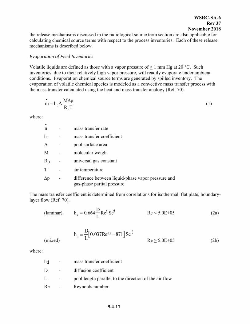
WSRC-SA-6 Rev 37
November 2018
9.4-17
the release mechanisms discussed in the radiological source term section are also applicable for calculating chemical source terms with respect to the process inventories. Each of these release mechanisms is described below.
Evaporation of Feed Inventories
Volatile liquids are defined as those with a vapor pressure of > 1 mm Hg at 20 °C. Such inventories, due to their relatively high vapor pressure, will readily evaporate under ambient conditions. Evaporation chemical source terms are generated by spilled inventory. The evaporation of volatile chemical species is modeled as a convective mass transfer process with the mass transfer calculated using the heat and mass transfer analogy (Ref. 70).
TR
pMAhm
ud
(1)
where:
m - mass transfer rate
hd - mass transfer coefficient
A - pool surface area
M - molecular weight
Ru - universal gas constant
T - air temperature
p - difference between liquid-phase vapor pressure and gas-phase partial pressure
The mass transfer coefficient is determined from correlations for isothermal, flat plate, boundary-layer flow (Ref. 70).
(laminar) Re < 5.0E+05 (2a)
(mixed) h
d
DL
0.037Re0.8871 Sc13
Re > 5.0E+05 (2b)
where:
hd - mass transfer coefficient
D - diffusion coefficient
L - pool length parallel to the direction of the air flow
Re - Reynolds number
hd 0.664D
LRe
12 Sc
13

WSRC-SA-6 Rev 37
November 2018
9.4-18
Sc - Schmidt number
The transition Reynolds number between laminar and turbulent flow regimes is approximately 5.0E+05 (Ref. 70).
The following assumptions are made in the calculation of chemical source terms due to evaporation:
The maximum potential inventory is released.
Upon release of inventory, an unmitigated, circular pool with a depth of 1 cm will be formed instantaneously.
The temperature of the air and the spilled inventory is 35°C.
Mass transfer (evaporation) occurs under isothermal conditions.
The concentration of the source term in the free stream is assumed to be negligible (i.e. p is equal to the liquid-phase vapor pressure).
The wind velocity is 4.5 m/s (Ref. 71).
Vessel Vapor Space Release of Feed Inventories
The vapor space of a vessel containing a volatile liquid will contain an amount of the liquid in the gas phase. The bounding chemical source term released from the vapor space of a vessel is calculated using the ideal-gas equation of state.
(3)
where:
- source term partial pressure
V - vessel volume
The following assumptions are made in the calculation of chemical species source terms released from the vapor space of a vessel:
The vapor space volume is assumed to be equal to the total vessel volume.
The partial pressure of the chemical in the vapor space is equal to the equivalent liquid-phase vapor pressure.
The temperature of the vapor space is 35°C.
The entire source term is released instantaneously from the vapor space.
Formic Acid Fires
The release mechanism discussed here deals with the chemical source term resulting from the combustion of formic acid. The chemical source terms are calculated assuming that complete
m pp vapor
VM
RuT
ppvapor

WSRC-SA-6 Rev 37
November 2018
9.4-19
combustion occurs at the fuel-air mixture’s UFL; this maximizes the potential formic acid source term. The Respirable Fraction (RF) for a given combustion product source term is calculated by
(4)
where:
RFi fire RF for the ith combustion product
Np,i number of moles of source term on the products side of the combustion chemical equation
Nc,i number of moles of combustible on the reactants side of the combustion chemical equation
Mp,i molecular weight of the ith combustion product
Mc,i molecular weight of combustible
The rate at which the fuel is consumed by the fire is determined from (Ref. 72)
)e1(mAm Dk-"
(5)
where:
m - mass loss rate for a finite pool fire
A - area of pool fire ''
m
- mass loss rate of an infinite pool fire
- pool size factor
D - pool diameter
The product of (4) and (5) yields the release rate of a given source term from the pool fire
iRFmm itermsource
(6)
while the duration of the fire is given by
mVρt (7)
where:
t - duration of fire
V - volume of fuel
- density of fuel
m - mass loss rate for a finite pool fire
RFi Np,i
Nc,i
Mp, i
Mc,i
k
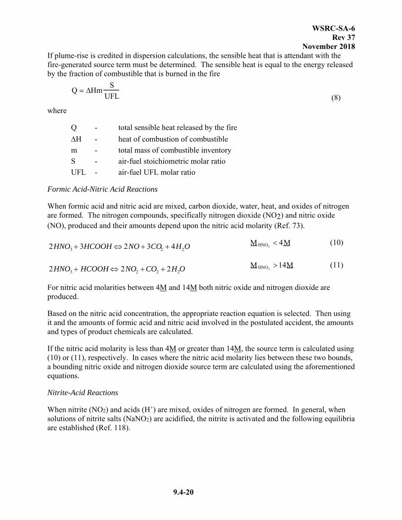
WSRC-SA-6 Rev 37
November 2018
9.4-20
If plume-rise is credited in dispersion calculations, the sensible heat that is attendant with the fire-generated source term must be determined. The sensible heat is equal to the energy released by the fraction of combustible that is burned in the fire
(8)
where
Q - total sensible heat released by the fire
H - heat of combustion of combustible
m - total mass of combustible inventory
S - air-fuel stoichiometric molar ratio
UFL - air-fuel UFL molar ratio
Formic Acid-Nitric Acid Reactions
When formic acid and nitric acid are mixed, carbon dioxide, water, heat, and oxides of nitrogen are formed. The nitrogen compounds, specifically nitrogen dioxide (NO2) and nitric oxide (NO), produced and their amounts depend upon the nitric acid molarity (Ref. 73).
(10)
(11)
For nitric acid molarities between 4M and 14M both nitric oxide and nitrogen dioxide are produced.
Based on the nitric acid concentration, the appropriate reaction equation is selected. Then using it and the amounts of formic acid and nitric acid involved in the postulated accident, the amounts and types of product chemicals are calculated.
If the nitric acid molarity is less than 4M or greater than 14M, the source term is calculated using (10) or (11), respectively. In cases where the nitric acid molarity lies between these two bounds, a bounding nitric oxide and nitrogen dioxide source term are calculated using the aforementioned equations.
Nitrite-Acid Reactions
When nitrite (NO2) and acids (H+) are mixed, oxides of nitrogen are formed. In general, when solutions of nitrite salts (NaNO2) are acidified, the nitrite is activated and the following equilibria are established (Ref. 118).
Q HmS
UFL
2HNO3 3HCOOH 2NO 3CO2 4H2OM HNO3
4M
2HNO3 HCOOH 2NO2 CO2 2H2OM HNO3
14M

WSRC-SA-6 Rev 37
November 2018
9.4-21
Formation of nitrous acid: H+ + NO2-= HNO2 (12)
Solutions of nitrous acid auto-oxidize to form nitrate and NO: 3HNO2 = H+ + NO3
- + 2NO + H2O (13)
NO rapidly oxidizes to form nitrogen dioxide NO2: 2NO + O2 2 NO2 (14)
Nonvolatile Liquid/Solid Feed Inventory Release (Feed Inventories)
Releases of nonvolatile chemical species that result in respirable source terms are assumed to occur only in conjunction with highly energetic accident events (e.g. detonations or deflagrations). Since no highly energetic events are postulated to occur in the accident scenarios pertaining to nonvolatile feed chemical inventories, no respirable source term is generated from these inventories.
Evaluation of Process Inventory Chemical Source Terms
A series of analyses have been performed to screen out the chemical source terms and consequences associated with the postulated accidents involving process inventories (Ref. 10, 11, and 169) (see Figure 9.4-1).
In S-CLC-S-00012, bounding source terms for the process inventories (prior to the introduction of ARP and MCU processing) were developed by assuming both an Airborne Release Fraction (ARF) and Respirable Fraction of 1.0 (Ref. 10). A bounding (conservatively assuming a receptor located at 640 m as opposed to the site boundary) dispersion factor was used to calculate downwind concentrations. The calculated concentrations were then screened against bounding (i.e., the most restrictive) offsite evaluation guidelines.
The source terms that yielded concentrations exceeding the evaluation guidelines were reevaluated in M-CLC-S-00463 (Ref. 11). In that analysis, offsite dispersion factors and phase-appropriate airborne RFs, corresponding to the source term generation mechanisms that occur in the postulated accident scenarios (see Section 9.4.1.2), were applied to the inventories. The resulting downwind concentrations (assuming a receptor located at 640m) were then compared against appropriate acceptance criteria.
For the 512-S hazard analysis (Ref. 120), the chemicals within the 512-S waste stream were compared against the limiting ST to exceed onsite (100 m receptor) and offsite (site boundary) EGs (Ref. 219). The analysis used the ERPGs or Temporary Emergency Exposure Limits (TEELs) associated with the individual chemicals along with 3-minute dispersion factors for the two receptors to calculate the limiting STs. The limiting STs are significantly higher than the bounding event ST from the 512-S hazard analysis (Ref. 125 and 219). Therefore, the chemical consequences in 512-S do not exceed EGs.
As part of the hazard evaluation for MCU processing (Ref. 169), the SE stream was determined to be within the previously characterized streams evaluated in the screening analysis excluding the solvent, which has a separate chemical evaluation done where the individual chemicals are
WSRC-SA-6 Rev 37
November 2018
9.4-22
compared to their Protective Action Criteria (PAC) values to determine if guidelines have been exceeded. Additional chemicals have been evaluated in a similar fashion in Reference 169 as the DWPF process has been modified, e.g., ADPs.
Based on the above described analyses, none of the release mechanisms associated with the postulated accident scenarios involving process inventories will yield source terms resulting in concentrations that exceed the evaluation guidelines.
Application of Release Mechanisms to Accident Scenarios
This section discusses the application of the release mechanisms described in the previous section to the inventories involved in the postulated accidents (Ref. 74).
Feed Inventories
The methodologies discussed above are applied explicitly to the feed inventories involved in a postulated accident scenario in order to calculate chemical source terms. Unlike the radiological inventories, none of the feed inventories are subject to more than one release mechanism in a given accident scenario. Therefore, no consideration needs to be given to potential interactions between release mechanisms.
Process Inventories
As discussed in Section 9.4.1.2, a series of analyses have been performed to demonstrate that, under bounding conditions, the process inventories cannot yield source terms that result in downwind concentrations that exceed the offsite acceptance criteria. By performing bounding analyses, any potential interactions between release mechanisms are accounted for.
Deposition and Filtration
The chemical source terms produced by the feed inventories are in the gas-phase; therefore, it is assumed that no deposition or filtration phenomena affect those source terms. Moreover, no deposition or filtration phenomena are credited in the evaluation of the bounding process inventory source terms.
9.4.1.3 Consequence Analysis Methodology
RADIOLOGICAL CONSEQUENCE ANALYSIS METHODOLOGY
Consequences of releases of radionuclides under postulated accident conditions were estimated with Version 1.13.1 of the MELCOR Accident Consequence Code System 2 (MACCS2) code (Ref. 135). MACCS2 models the dispersion of radioactivity in the atmosphere from the nuclear facility and computes plume depletion effects. MACCS2 then calculates the effects of this radioactivity to downwind receptors and to the environment. During plume passage, doses and associated health effects are computed for inhalation from the plume, immersion or cloudshine, groundshine, deposition on the skin, and inhalation of resuspended ground contamination. Long-term effects such as ground contamination and
WSRC-SA-6 Rev 37
November 2018
9.4-23
economic impacts, and ingestion of contaminated water and foodstuffs, inhalation of resuspended material, and groundshine to the individual may also be calculated.
MACCS2 predicts dispersion of radionuclides by the use of multiple, straight-line Gaussian plumes (with Tadmor-Gur set of dispersion coefficients). Although each plume treats the released material as a neutrally buoyant gas, the direction, duration, sensible heat, and initial radionuclide concentration may be varied from plume to plume. Cross-wind dispersion is treated by a multi-step function and both wet and dry depositions features can be modeled as independent processes. Meteorological variability is treated with a stratified random sampling algorithm. Typically, a Latin Hypercube Sampling model of site-specific meteorological data is specified. Based on this sampling and dose and health effects models, a Complementary Cumulative Distribution Function (CCDF) is calculated for the consequence of interest. The average, median, peak, 90 th, 95th, 99 th , and 99.5th quantile doses are output in a tabular format.
The regulatory basis for obtaining meteorological data and performing dispersion analyses is cited in DOE-STD-3009-94 (Ref. 6). DOE-STD-3009-94 invokes Regulatory Guide 1.145, Position 1.2 and Position 3 (Ref. 17), and Regulatory Guide 1.23 (Ref. 194). The DWPF demonstrates compliance with Regulatory Guide 1.145 (Ref. 17) and Regulatory Guide 1.23 (Ref. 194) in Reference 195.
The results of the MACCS2 calculations are given in the tables of maximum resultant TEDE over various release periods (e.g., 3 minute, 20 minute, 1 hr, 2 hr, 8 hr, and 10 hr). The TEDE per unit gallon is used to determine the TEDE incurred by the receptor of interest from the amount of material (typically in gallons as applied in the DBAs) that is released into the atmosphere at the location of the event. The receptors of interest are the Onsite receptor at 100 meters and the Offsite receptor at the site boundary. The Onsite TEDE values are reported at the 50th quantile dose level and the Offsite TEDE values are reported at the 95th quantile dose level according to References 144 and 6, respectively. The unit TEDE values used for various release mechanisms and durations are taken from Reference 173.
In addition to determining the consequence to the offsite public, the quantitative analyses performed for design basis events included consequence determination to the onsite receptor. These calculations differ in the distance from the release to the receptor and the statistical confidence level for the assumed meteorological stability; these offsite consequence calculations used meteorological data at the 95th percentile confidence level while the onsite receptor was determined using 50th percentile data.
DOE-EM issued a memorandum in July 2006 with interim guidance applicable to accident analysis calculations with a standardized IGEG of 100 rem at 100 meters for onsite receptors (Ref. 185). Additionally, the IG prescribed specific dispersion modeling attributes to be used in the calculations for onsite receptors. The IG specifies use of 95th percentile meteorological data and use of a surface roughness factor of 3 cm. These attributes in the dispersion model result in an increase in 100 meter onsite receptor consequences by a factor of approximately ten (10X) compared to the previous attributes applied to onsite receptor consequences, i.e., 50th percentile meteorological data and 100 cm surface roughness factor (Ref. 186).
WSRC-SA-6 Rev 37
November 2018
9.4-24
An assessment of DWPF onsite receptor consequences identified in the DBAs, with the IG attributes applied, determined that no additional SS controls would be warranted, thus confirming the adequacy of the controls selected previously for these events. The assessment did not include events in the hazard analyses that did not carry forward into the Accident Analysis, nor did it include NPH roll-up events (Ref. 186). For these events, the traditional attributes were applied to the consequences.
The set of unit TEDE values used in each of the individual accidents is specified in each accident consequence calculation. It should be noted that the IDP limits on the Sludge and MST/Sludge Solids Streams are more restrictive than the streams that were used to calculate the TEDE values. These restrictions on the IDP also impact the SRAT, Recycle, DWTT, and Melter Off-gas Streams. The consequences for the vessel explosions and pool fires involving those streams are calculated to reflect the more restrictive IDP limits (Ref. 214).
The cloudshine and groundshine DCFs used are based on Federal Guidance Report 12 (Ref. 138). The inhalation 50-year Cumulative Effective Dose Equivalent (CEDE) DCFs were based on Publication 68 and 72 of the International Commission on Radiological Protection (ICRP) (Ref. 140 and 141) as taken from the ICRP Dose Coefficient Database Compact Disc (Ref. 142). The receptor population will be an adult worker and an adult member of the general public.
ICRP Publications 68 and 72 (Ref. 139 and 140) give inhalation DCFs for the worker and general public. These values are based on the ICRPs 1990 recommendations on radiation protection standards in Publication 60 (Ref. 142), as well as the revised kinetic and dosimetric model of the respiratory tract in Publication 66 (Ref. 139). Since the issuance of ICRP Publications 68 and 72 (Ref. 140 and 141), the ICRP has issued a compact disc with a dose coefficient database (Ref. 142) using the same models. The database gives both organ and effective dose coefficients. Additionally, the database gives the user greater flexibility by including dose coefficients for ten particle sizes and ten commitment time periods as well as six ages at exposure.
For a workplace population, ICRP Publication 68 (Ref. 140) recommends a particle size of 5 μm Activity Median Aerodynamic Diameter (AMAD) as a default value, which is considered to be representative of workplace aerosols. For members of the general public, ICRP Publication 71 (Ref. 143) recommends a particle size of 1 µm AMAD as a default value. In general, 5 µm was used for onsite while 1 µm was used for offsite.
CHEMICAL CONSEQUENCE ANALYSIS METHODOLOGY
Chemical consequence calculations are limited to airborne releases because this typically represents the most immediately significant route of public exposure in an accident scenario (Ref. 71). Some of the air dispersion modeling utilizes the ALOHA computer code and the Gaussian finite release model developed and validated by E. Palazzi (Ref. 80 and 81).
There are two separate dispersion models in ALOHA: Gaussian and heavy gas modeling. ALOHA uses a Gaussian dispersion model to describe the movement and spreading of a gas that is neutrally buoyant, while heavy gas dispersion calculations in ALOHA use the DEGADIS

WSRC-SA-6 Rev 37
November 2018
9.4-25
model (Ref. 82). The DEGADIS model was selected because of its general acceptance and because of the extensive testing that was carried out by the authors. ALOHA uses the friction Richardson Number as the criterion for Gaussian or heavy gas modeling.
A potential limitation of the ALOHA code is its inability to model relatively long-duration releases. Currently, the code is limited to either modeling a 1-hour (continuous) or a 1-minute (instantaneous) release. In order to model longer release durations in the course of modeling fires or deflagrations in the accident analyses documented here, manual calculations were performed using the same Palazzi model employed in ALOHA for neutrally buoyant plumes. Since the source terms considered in these longer duration releases are at elevated temperatures as a result of a fire or deflagration, the density of the gas is less than that of air. Therefore, the Palazzi model, which uses the Gaussian correlation, is appropriate. In addition to crediting the elevated temperature of the gas for the Gaussian model, the fire events incorporate a plume rise component as described in DOE/TIC-11223 for events that occur outside the confines of a structure (Ref. 83).
The meteorology for either of the two dispersion methodologies is specified in WSRC-MS-92-206 (Ref. 71). A D-stability class and a 4.5 m/s wind speed are used. These meteorological conditions conservatively address source term generation as well as dispersion and are consistent with those used to generate the amount of material becoming airborne following a spill.
For the 512-S chemical evaluation, the onsite and offsite receptors use dilution factors (χ/Q) based on a Gaussian plume model but calculated with MACCS code. For the χ/Q, 100-cm surface roughness is assumed and 50th quantile used for the onsite receptor while 95th quantile is used for the offsite receptor. For the solvent chemical analysis in Reference 169, the onsite and offsite receptor uses a χ/Q calculated with MACCS2 code (Ref. 173) instead of ALOHA. For the ADP chemical analysis (Ref. 169), the onsite receptor uses a χ/Q value for dispersion as specified in DOE-STD-1189 (Ref. 217). The offsite receptor χ/Q is calculated using the MACCS2 code, assuming an F-stability class with a 1.3-m/s wind speed and 160-cm surface roughness. These represent the Code of Record at the time the analysis was performed.
Concentrations for comparison with guidelines are calculated as the peak 15-minute average concentrations (Ref. 71).
9.4.1.4 Acceptance Criteria
While DOE Standard 3009-94 describes a process of comparing accident analysis results against a set of evaluation guidelines, it does not provide those guidelines specifically (Ref. 6). Thus, the evaluation guidelines or acceptance criteria against which these accident analyses were compared are taken from Manual E7, Procedure 2.25, Functional Classification and Procedure 2.25A, LW Functional Classification, approved for general use at the Savannah River Site (SRS) (Ref. 3, 132, and 215). Evaluation guidelines for accident analyses associated with primary CHAs for the facility are based on Manual E7, Procedure 2.25, Revision 13 (or later) and Procedure 2.25A, Revision 1 (Ref. 132 and 215). This revision sets the evaluation guidelines for the maximally exposed offsite individual at 25 rem, regardless of the frequency of the event being evaluated. The PHA events are evaluated to the criteria established in Manual E7
WSRC-SA-6 Rev 37
November 2018
9.4-26
Procedure 2.25, Revision 3 (Ref. 3). These acceptance criteria are applied to the radiological and chemical consequences experienced by the offsite individual at the site boundary. The criteria depend on the frequency of the accident and are identical to the criteria used to identify Safety Class Items (SCIs) (Ref. 3 and 71). The acceptance criteria for radiological and chemical consequences of accident events are given in Tables 9.4-15a and b and in E7, 2.25 Revision 3 and 13 respectively.
The evaluation guideline for acceptable consequences to the onsite receptor is provided in DOE-EM interim guidance (Ref. 185). Events exceeding 100 rem to the onsite receptor at 100 meters, when analyzed per the specifications in Reference 185, require SS controls.
Table 9.4-15a also includes qualitative descriptions for accident frequency categories: anticipated events, unlikely events, and extremely unlikely events. Anticipated events are incidents that may occur several times during the lifetime of the facility. Unlikely events are accidents that may occur at some time during the lifetime of the facility. Extremely unlikely events are accidents that will probably not occur during the lifetime of the facility. Beyond
extremely unlikely events are accidents with frequencies less than 1E-06 yr-1. According to Manual E7, Procedure 2.25 Revision 14 (Ref. 162), credible external man-made events with a
frequency of 1E-06 yr-1 as conservatively estimated, or 1E-07 yr-1 as realistically estimated are not considered credible and have no accepted evaluation guidelines. NPH events are evaluated at the frequency specified by DOE-STD-1020. Process related internal events that are not covered by external or NPH events are assumed to be credible events, regardless of frequency. An evaluation was performed and documented in Reference 163 that evaluated the accidents defined in the DWPF Preliminary Hazards Analysis (Ref. 5); Probabilistic Safety Analysis (PSA) (Ref. 1); and in this FSAR to determine the impact of eliminating the frequency cut off to define credible scenarios for internal events in response to Manual E7, Procedure 2.25 Revision 14 (Ref. 162). Based on the evaluation, it was found that no internal events with significant consequences were eliminated from controls consideration based on frequency, and therefore, no further evaluation is required for compliance with Manual E7, Procedure 2.25 Revision 14 (Ref. 162).
Evaluation guidelines (EGs) are based on the accident frequencies established for the bounding unmitigated scenarios except when the event frequency is reduced by safety class controls. In addition, for purposes of choosing applicable EGs, a frequency of "beyond extremely unlikely" was assumed to be equivalent to "extremely unlikely".
For chemical consequence acceptance criteria, chemical concentrations are first calculated as peak 15-minute average values. This is the applicable value for all chemicals for which the toxicity effect is immediate. If this procedure yields overly conservative results for chemicals whose toxic effects are dose-dependent, then for those chemicals only, the peak 1-hour average concentration may be used as the basis for comparison to the acceptance criteria (note that there are currently no dose-dependent chemicals modeled for DWPF). A 15-minute duration is utilized for all chemical analyses performed for DWPF.

WSRC-SA-6 Rev 37
November 2018
9.4-27
The Incremental Cancer Risk (ICR) criteria are chosen to give equivalent cancer-risk values to comparable radiological dose limits. These ICR criteria are only applied to carcinogenic chemicals. For the DWPF analyses, there are no significant carcinogenic consequences.
If the chemical concentration criteria given in Table 9.4-15a are not available for a given chemical species, other comparable acceptance criteria may be substituted. The acceptable hierarchy of substitutions for each concentration given in Table 9.4-15a is presented in Table 9.4-16. Note that the protocol is to work downward (i.e., the first alternative limit given in Table 9.4-16 for a Table 9.4-15a concentration limit is the most acceptable). With the DWPF CHA chemical analyses performed, the concentration acceptance criteria used is the PAC values, which are the most current developed criteria and may be based on one of three values (Acute Exposure Guideline Levels [AEGLs], ERPGs, or TEEL data sets).
9.4.2 EVALUATION OF ACCIDENTS
The hazard analysis of DWPF, detailed in Section 9.3, resulted in a list of potential accident classes requiring further consideration. These accident classes have the potential for significant offsite or onsite consequences according to the frequency and consequence severity estimates assigned during the hazard analyses process. Each of these hazards is addressed in this section. The unmitigated events have been quantitatively analyzed directly or are bounded by the analysis described in this section. The events are grouped by the PHA BIN numbers 8 through 5 which reflect the applicable event frequency and associated unmitigated consequence severity designator found in Figure 9.3-1.
EXPLOSION HAZARDS (BIN #8)
Event 1 Deleted.
Event 2 Deleted
Event 3 CPC and SPC Explosions cannot occur because the bulk vapor space cannot reach CLFL within 4 days as addressed in Reference 133.
Event 4 CPC and SPC Vessel Explosions: The CPC and SPC Vessel Explosions are addressed in Section 9.4.2.1. Explosions in the OGCT/BUOGCT are addressed in Section 9.4.2.3.
The SME and SRAT condensers are part of the vessels and respond in accident conditions similar to the SME and SRAT.
The FAVC is part of the process vessel ventilation system and fails coincident with the associated vessel failure. The dose contribution from the FAVC is negligible.
FIRE HAZARDS (BIN #8)
Event 5 Deleted
Event 6 Deleted

WSRC-SA-6 Rev 37
November 2018
9.4-28
Event 7 Organic fire of Isopar L in the CPC and SPC from receiving MCU Strip Effluent. The dose contribution from the pool fire is negligible as described in Reference 169.
Event 8 Fires in the CPC and SPC vessels are evaluated as part of the Event 4 propagation. The fuel consists of the Isopar L carried over from MCU with the Strip Effluent.
Event 9 Ammonium-Nitrate (AN) fire in the process vessel ventilation system - The annual AN accumulation estimation without the use of scrubbers is less than 1.5 kg (Ref. 184). This amount of AN is expected to sublimate at or above the accumulation rate and does not present a fire hazard.
Event 10 Deleted
MECHANICAL CONFINEMENT BREACH (BIN #8)
Event 11 Crane load drop has been identified as an initiator for multiple events in Section 9.4.2.
EXPLOSION HAZARDS (BIN #6)
Event 12 Deleted
Event 13 An explosion in the process vessel ventilation system - The accumulation of AN with high boiler organics was investigated by DWPF. The ratio of AN to organic was determined by analyzing samples taken from the prototype vessel vent system at TNX. These samples were found to have high concentrations of organic in the AN. Low AN concentration (typical 1.5 wt.% to max. 23 wt.%) materials are not in the detonation range as stated in Reference 86 and do not present an explosion hazard.
The annual accumulation estimation of ammonium nitrate without the use of scrubbers is less than 1.5 kg per year. This small amount of ammonium nitrate is not considered to be an explosion hazard (Ref. 100 and 184).
Event 14 Explosion in the Melter Off-gas is addressed in Section 9.4.2.3.
Event 15 RCT formic acid interaction with nitric acid from the DWTT is no longer an event since the CPC utilizes the nitric acid flow sheet where high or moderate concentrations of formic acid are no longer processed in the RCT. Accordingly, there is not a formic/nitric acid interaction in the RCT. The DWPF has been assessed in the PSA and determined that an uncontrolled reaction could occur in the SRAT or SME (Ref. 1). This event is addressed in Section 9.4.2.11.
Event 16 The melter explosion from the interaction of water and molten salt gall is addressed in Section 9.4.2.5.
Event 17 Deleted

WSRC-SA-6 Rev 37
November 2018
9.4-29
Event 18 Cooling coil failure is bounded by the SRAT spill scenario addressed in Section 9.4.2.7.
Event 19 High pressure water-driven mercury pump failure is bounded by the SRAT spill addressed in Section 9.4.2.7.
FIRE HAZARD (BIN #6)
Event 20 Electrical cable fire in the CPC/SPC vessels. This event is bounded by Event 4 with the follow on organic pool fires of Isopar L.
Event 21 A failure of the melter because of shorted electrodes. This event is bounded by the event described in the melter off-gas scenario in Section 9.4.2.3. This event describes loss of the melter despite SC SSCs. The melter off-gas release is more severe than a complete melter spill which cools and reduces the effectiveness of high temperature volatilization.
MECHANICAL CONFINEMENT BREACH HAZARD (BIN #6)
Event 22, Higher HP agitator (SRAT/SME) failures may cause an impeller blade to be 23, 24 thrown from the shaft into the process slurry. An analysis of this event
indicated that it is extremely unlikely that the blade would penetrate a coil or the vessel (Ref. 41). Assuming it could fail the coil or tank and spill the vessel contents, this event is bounded by the SRAT spill addressed in Section 9.4.2.7.
Event 25 Sample and transfer pump failures causing CPC vessel damage is not judged credible since the impellers are housed in a large steel casing supported high in the vessels by the pump casing support column. Process fluid is forced up to the impeller through a suction tailpipe with priming water. It has been judged extremely unlikely in the PHA that pump failure will occur. Mechanical failure of the vessel causing process leakage is not judged possible since the impeller would have to fail the impeller casing and fail the vessel head or wall. All process vessels have 1/2 inch thick minimum heads and walls. Pump casings are above the liquid surface and leakage from a vessel if it were to fail would be low.
CHEMICAL CONFINEMENT BREACH HAZARD (BIN #6)
Event 27 Uncontrolled reactions in the CPC vessels have been analyzed as addressed in Section 9.4.2.11.
Event 28 Formic and nitric acid interaction in the RCT is bounded by the uncontrolled reaction scenario described for the CPC vessels in Section 9.4.2.11. See also Event 15.
WSRC-SA-6 Rev 37
November 2018
9.4-30
EXPLOSION HAZARD (BIN #5)
Event 29 Explosions in the LPPP vessels have been analyzed and are addressed in Section 9.4.2.4. LPPP cell explosions cannot occur because the bulk vapor space cannot reach the CLFL within 4 days as addressed in Reference 133.
FIRE HAZARD (BIN #5)
Event 30 Precipitate and sludge tank agitator and transfer pump motor fires in the LPPP will not cause a radioactive release hazard by themselves. The motor fires are only one of several ignition sources. Explosions of the tanks are addressed in Section 9.4.2.
Event 31 Deleted
NATURAL PHENOMENA
Though not addressed by the PHA, analysis of natural phenomena events is included to ensure complete evaluation of facility safety (Ref. 5). Seismic events are addressed in Section 9.4.2.13, and high wind events are addressed in Section 9.4.2.14. Occurrence frequencies and potential consequences of rain (including flooding), snow, ice, lightning, meteorites, and freezing temperatures were considered and found to pose insignificant risk to DWPF operation (Ref. 87).
EXTERNAL HAZARDS
Externally initiated, man-made events were considered as well to ensure complete evaluation of facility safety. Radiological and chemical releases due to Airplane, helicopter, train, initiated events are examined and determined not to be credible.
The likelihood of an airplane crash impacting the DWPF is not credible (Ref. 97). However, the largest structure (and therefore, most likely to be crashed into) at DWPF is the Vitrification Building. Since the materials in the Vitrification Building are housed within reinforced concrete walls, the contents are protected from missiles and fuel fires, and it is not credible that an airplane crash will cause a chemical or radioactive material release.
The likelihood of a helicopter crash impacting the DWPF other than the Vitrification Building or GWSB #1 is not credible (Ref. 98) (GWSB#2 has a similar profile as GWSB#1, so the likelihood of impact is the same as GWSB#1). Since the materials in the GWSBs and the Vitrification Building are housed within a reinforced concrete structure, the contents are protected from missiles and fuel fires. It is not credible that a helicopter crash will cause a chemical or radioactive material release from these facilities.
A train could drive through the end of the track leading into the Vitrification Building. A train that fails to stop on entering the Railroad Well, over runs the rail bumper, and impacts the wall can be caused by human error or equipment malfunction. It is hypothesized that a train consisting of a switching engine and two loaded flatcars can back into the RW for unloading operations, fail to stop, and strike the center of the wall at the rear flatcar coupler level. It has been determined that a train accident at a speed of 10
WSRC-SA-6 Rev 37
November 2018
9.4-31
mph or higher is not credible in DWPF, but a low-speed accident could occur (Ref. 99). However, since the materials in the Vitrification Building are housed within reinforced concrete walls, the contents are protected from externally generated missiles or fires, and it is not credible that a train accident will cause a chemical or radioactive material release.
ANTICIPATED OPERATOR ACTION
For all events that are not prevented, operator action is anticipated to terminate these events as soon as possible. The TSR administrative control, Section 5.8, requires a procedures program for Alarm Responses Procedures, Abnormal Operating Procedures (AOPs) and Emergency Operating Procedures (EOPs) to establish a controlled response to upset and accident conditions. These procedures use DCS and operator actions as well as safety class and safety significant SSCs. Other actions such as temporary modifications may be used when required to prevent or mitigate accidents.
Accidents described in the following sections as well as those specified in Tables 9.3-10 and 9.3-11 were conservatively analyzed to determine the maximum dose assuming the entire applicable recovery time, i.e. 8 hours or 4 days without operator intervention. However, operator action is anticipated to restore the facility to an acceptable operating mode as soon as possible using applicable Alarm Response Procedures, AOPs, EOPs, response plans or other methods as warranted.
Operator actions are not anticipated for the bounding scenarios that breach the canyon, LPPP, or 512-S walls releasing material to the environment. These scenarios were developed to determine the maximum dose to an offsite individual and onsite receptor from DWPF operations. The installation of safety class and/or safety significant equipment and instrumentation, TSR administrative controls, and operating procedures reduce the frequency of occurrence of these events to beyond extremely unlikely (<1.0E-06/yr.), and are actually
<10-9/yr. Therefore, operator actions needed to terminate these events have not been determined; however, the event would be considered terminated once negative pressure was reestablished in the ventilation systems.
9.4.2.1 Explosion in the CPC/SPC Vessels
9.4.2.1.1 SCENARIO DEVELOPMENT
Background
Explosions are possible in the CPC/SPC vessels (SEFT, PRFT, SRAT, SME, SMECT, MFT, RCT and DWTT) due to the accumulation of flammable vapors in the vessels’ vapor space.
Hydrogen is generated in the CPC/SPC vessels due to both radiolytic and catalytic hydrogen generation. Radiolytic hydrogen generation due to radiolysis of water (organics contribute when present) occurs in CPC/SPC vessels. Catalytic hydrogen generation is limited to those vessels that have the potential to contain formic acid and sludge (SRAT, SME, SMECT, MFT, RCT, and DWTT). Formic acid reacts in the presence of the noble metals in sludge to produce hydrogen. Administrative controls are provided to limit the chemical additions to the tank. Reference 222

WSRC-SA-6 Rev 37
November 2018
9.4-32
acknowledges the potential for the generation of hydrogen due to thermolytic decomposition of process stream constituents; however, it is concluded thermolytic decomposition is negligible compared to other combined mechanisms in vessels where it is possible. Additionally, the waste can potentially retain hydrogen in the event that the vessel is not being agitated. When the waste is agitated (by the agitator or other disturbance), this can result in a sudden release of the retained hydrogen from the waste to the vessel vapor space. The vessels in which significant hydrogen may be retained are the SRAT, SME, and MFT (Ref. 169).
The primary organic of concern is Isopar L which is introduced to the process in the Strip Effluent Stream transferred from MCU to the SEFT. Isopar L may be present in the SEFT, the PRFT (due to leakage through the three-way valve), the SRAT (as a result of a transfer from the SEFT or PRFT), the SMECT (due to carryover events from the SRAT), the RCT (from the SMECT or transfers from sumps), and the DWTT (due to decontamination of Isopar L contaminated equipment). The concentration of Isopar L and other organics received into the facility is controlled by the WAC and the SEFT Dilution Program. Isopar L and other organics enter the vessels’ vapor space by evaporating at the liquid surface and diffusing into the tank vapor space driven by thermal gradients within the tank. In the SEFT and PRFT, controls are in place to limit the concentration in the vapor space by maintaining a maximum liquid temperature in these vessels which limits the concentration in the vapor space due to the vapor pressure of Isopar L. In the SRAT, the Isopar L is steam stripped by feeding the SEFT and PRFT at a controlled feed rate while boiling the SRAT. This steam strips the Isopar L and prevents carryover to other downstream vessels (SME, SMECT, MFT). Isopar L may be carried over with the SRAT process material in the overflow to the SMECT if the SRAT fails to steam strip and remove the Isopar L or if the Isopar L concentration in the Strip Effluent feed is too high. High Isopar L concentrations in the SRAT vapor space can also cause the Isopar L off-gas to condense in the SRAT condenser train (SRAT condenser, SRAT ammonia scrubber and FAVC) and eventually drain to the SMECT and other vessels downstream of the SRAT. The concentration of Isopar L in the DWTT is based on bounding amounts which could be present on or contained in equipment being decontaminated. The concentration of organics (Isopar L and ammonia) in the RCT is controlled by an administrative control on Waste Tank Contents.
Additional organics are present in the vessels from the addition and degradation of antifoam. Antifoam is added to the SRAT and SME to reduce foaming and waste carryover to the SMECT. The antifoam degrades into flammable organics (HMDSO, TMS, and propanal) that are then released into the vessel vapor space. The ADPs may be present in the SRAT and SME (direct addition of antifoam), the SMECT (carryover and/or condensate from the SRAT or SME), the MFT (transfer from the SME), and the RCT (transfer from the SMECT). There are de minimis quantities of the ADPs in the DWTT and CPC sumps and are therefore not considered in the accident analysis. After each antifoam addition to the SRAT or SME, some ADPs are immediately released into the vessel vapor spaces upon reaching boiling temperatures. Some quantities of the organics condense and are carried into the SMECT and downstream. Improper addition of antifoam results in more degradation and generation of the organics. An administrative control is provided to control the additions of antifoam and conditions of the process vessels when adding antifoam.

WSRC-SA-6 Rev 37
November 2018
9.4-33
Another flammability concern is ammonia. Ammonia is assumed to be present in the RCT (when tank contents are alkaline) due to the ammonia created in the SRAT as part of the formic acid reactions in the vessel. The ammonia leaves the SRAT as a vapor and is captured by the SRAT ammonia scrubber where a dilute nitric acid stream scrubs the ammonia from the offgas. The scrubber solution drains to the SMECT and is subsequently transferred to the RCT. When caustic additions are made to the RCT, the ammonia may be released to the RCT vapor space.
The purge for each of the vessels is based on the calculated flow rate required to maintain the vapor space below flammability limits for hydrogen, Isopar L, ADPs, and ammonia, where applicable. For the vessels with interlocks (SRAT, SME, SEFT, and PRFT) the flammability limit is 60% CLFL and for the vessels without interlocks (SMECT, MFT, RCT, and DWTT) the flammability limit is 25% CLFL.
Accident Initiators
Two scenarios are considered for CPC/SPC vessel explosions. The following are potential accident initiators for those scenarios:
Scenario 1 includes initiators resulting in high concentrations of Isopar L released or higher hydrogen generation rates in the vapor space exceeding CLFL as well as failure of purge due to crane load drops:
1. Inadequate purge to a vessel results in the accumulation of flammable vapors above CLFL.
2. In the SEFT, the bulk liquid temperature exceeds the value upon which the purge was based due to heat from the agitator, pumps, or inlet feed. The high temperature remains uncorrected due to detection failure or operator response failure. This results in an accumulation of organics in the vapor space which exceeds CLFL.
3. A failure of the three-way valve causes organic in the Strip Effluent, from the SEFT, to leak into the PRFT. In the PRFT, the bulk liquid temperature exceeds the value upon which the purge was based due to heat from the agitator, pumps, or inlet feed. The high temperature remains uncorrected due to detection failure or operator response failure resulting in an accumulation of organics in the vapor space above CLFL.
4. In the SRAT, SE is introduced without the vessel’s contents boiling which leads to the accumulation of organics. One reason for a no-boiling scenario is the minimum steam flow is not maintained. When the material is subsequently heated up, the higher concentration of organics is released which exceeds CLFL in the vapor space.
5. In the SRAT, the SE is introduced at a higher feed rate or at a higher concentration than assumed in the purge calculation which results in the accumulation of organics and exceeds CLFL.
6. In the SRAT, SME, and MFT, during operations flammable conditions may occur if there are excess noble metals and if transfer errors (excess nitric acid, excess formic acid, or an excess feed rate) cause hydrogen generation in the vessels to exceed the purge capacity.
7. In the SME, MFT, SMECT, and RCT, organics are allowed to accumulate due to inadequate removal in the SRAT. These organics are released and exceed the CLFL in the vessels.
WSRC-SA-6 Rev 37
November 2018
9.4-34
8. During limited processing, standby, or shutdown, the SRAT, SME, or DWTT vapor space could become explosive if the temperature rises and increases the hydrogen production associated with formic acid decomposition. The increased hydrogen production may exceed the dilution capacity of the air/nitrogen purge system.
9. A crane load drop could fail CPC or SPC vessel purge jumpers resulting in a loss of purge flow that causes a CPC or SPC vessel explosion from the subsequent buildup of organic and hydrogen vapors in the purge space.
10. The SEFT receives strip effluent with an excessive Isopar L concentration. The high Isopar L concentration results in a release of Isopar L into the vapor space of the SEFT which exceeds the CLFL in the SEFT vapor space.
Scenario 2 includes specific initiators for increased concentrations of ADPs or retention of hydrogen in the waste.
1. In the SRAT or SME, improper additions of antifoam result in exceeding the concentrations assumed in the purge calculations which results in the accumulation of organics and exceeds CLFL. Higher ADP concentrations can then be carried over into downstream vessels and released into the vapor space exceeding CLFL in the vessels.
2. In the SRAT, SME, or MFT the agitator is off allowing hydrogen to build up in the waste, which is then released upon agitation of the waste (with the agitator or other mechanism), and exceeds the CLFL in the vessels.
In each of the above initiators, it is assumed a spark source is present and an explosion occurs.
Bounding Unmitigated Scenario
Regardless of the initiating vessel, the accident progression of the bounding unmitigated scenario (same for scenarios 1 and 2 with different initiators) is assumed to progress as follows:
A CPC/SPC vessel exceeds CLFL. The CLFL can be exceeded in one or more vessels if the feed or chemical additions are not within specifications, feed or chemical additions occur during off-normal operating conditions, excessive hydrogen generation occurs, gas chromatograph interlocks in the SRAT/SME fail to react to excessive CLFL conditions, temperature limits in a vessel are exceeded, retained hydrogen accumulates in the waste from period of no agitation and released upon agitation of the waste (with the agitator or other mechanism), or purge flow is inadequate. Purge flow can be inadequate due to many reasons. Once the CLFL is exceeded, and an explosion in the vessel occurs which overpressurizes the cell, dislodging the cell covers, resulting in the cell covers falling back into the cell or other cells. The falling cell covers fail the purge jumpers resulting in a loss of vessel purge flow, which causes the remaining vessels in the CPC and SPC to detonate. The SMECT is assumed to contain radioactive material due to SRAT carryover. The SEFT and PRFT are assumed to contain a mixture of Strip Effluent and MST/Sludge Solids due to leakage by the three-way valve. Since organic solvent can be present in the SEFT, PRFT, SRAT and SMECT, the detonation ignites a floating layer of Isopar L that can form on the surface of the liquid leading to a subsequent pool fire in these vessels. Falling debris or structural failure crushes the glass canisters within the Vitrification Building. In the melt cell the falling debris or cell covers breach the melter
WSRC-SA-6 Rev 37
November 2018
9.4-35
off-gas system, allowing the heated molten glass in the melter to vent to the cell. The releases are unmitigated with no filtration or deposition and continue for 4 days, after which the accident is assumed to terminate.
Mitigated Accident Progression
Safety Class Mitigated Scenario
The safety class mitigated scenario is the same as the bounding unmitigated scenario.
Safety Significant Mitigated Scenario
The safety significant mitigated Scenario 1 is prevented with the following controls. The primary level of control to prevent explosions in the CPC/SPC vessels is the Safety Grade Nitrogen Purge System. An additional primary control is the Load Lift Program to prevent crane load drops from impacting the safety related equipment identified for vessel explosion in the CPC and SPC. The second level of control to prevent the event is the Primary Purge System. The third level of mitigated control is the Zone 1 Ventilation System which provides a DF of 200 following the event for all releases but from 8 of the crushed canisters.
The first and second levels of control are supported by several controls in each of the process vessels to ensure the assumptions in the purge calculations remain valid:
WAC - The assumed hydrogen generation rates in the CPC/SPC vessels are ensured through the TSR WAC control.
SEFT/PRFT - The amount of purge required is based on the organic vapor concentration in the vapor space and the generation rate of hydrogen. The amount of organic vapor in the vapor space is controlled by limiting the liquid temperature in the vessel and the concentration of the organic in the liquid. The controls to support the organic concentration in the vapor space are:
o SEFT/PRFT Temperature Instrumentation - Instrumentation monitors the temperature in the vessel liquid to ensure the temperature remains below the maximum temperature assumed in the safety analyses. To prevent the maximum liquid temperature from being exceeded, the temperature instrumentation interlocks heat sources in the vessel (i.e., agitator, sample pump and transfer pump) upon detection of high temperature. The temperature interlocks prevent an increase in temperature which would increase the organic vapor concentration in the vapor space above that assumed in the purge determination. A lower temperature limits the concentration at any region in the vapor space and therefore prevents any concern related to the formation of a flammable vapor layer. At liquid levels below the temperature sensing instrumentation, a complete release of Isopar L will not cause a flammable condition to occur if the Isopar L concentration is maintained less than or equal to 87 mg/l (Ref. 206 and 207).
o WAC and the SEFT Dilution Program - The concentration of organics in the waste is protected by the WAC and the SEFT Dilution Program. The WAC ensures the SE is characterized prior to receipt in the CPC and the SEFT Dilution Program ensures the bulk concentration of Isopar L in the SEFT remains less than or equal to 87 mg/L.

WSRC-SA-6 Rev 37
November 2018
9.4-36
o SEFT/PRFT TSR Control on Feed Addition - This control stops material transfers into the SEFT and PRFT upon indication of high temperature. This prevents the further increase in flammable fuel generation in the vessel vaporspace.
Chemical Controls Program - The hydrogen from catalytic generation in the SRAT and SME is controlled by limiting the addition of nitric and formic acid to these vessels.
SRAT/SME Purge Flow Interlocks - Purge flow is indicated on credited purge flow meters, and interlocks are provided upon the detection of low purge flow. The interlocks are required due to the short time to LFL in these vessels following the loss of purge. The low purge flow interlock isolates heat sources (i.e., steam) and sources of catalytic hydrogen generation (i.e., formic acid, nitric acid, and frit addition) from the vessels.
SRAT/SME Gas Chromatograph Interlocks - In the event the assumed hydrogen generation rate is exceeded in the SRAT and SME, gas chromatographs with associated interlocks are provided to prevent explosions in the SRAT/SME and the connected vent piping. This system monitors the percent of LFL in these vessels and interlocks upon exceeding 60% of LFL. The gas chromatograph interlock isolates heat sources (i.e., steam) and sources of catalytic hydrogen generation (i.e., formic acid, nitric acid, and frit addition) from the vessels.
SRAT Controls for Organics Removal - The organics assumed to be present in the vessel vapor space are dependent on the concentration of organics in the waste, the flow rate of transfers from the SEFT and PRFT, and the rate of steam stripping in the SRAT vessel. The organic concentration, transfer flow rates, and rate of stream stripping are limited by the following controls.
o WAC and the SEFT Dilution Program - The concentration of organics in the waste is protected by the WAC and the SEFT Dilution Program. The WAC ensures the SE is characterized prior to receipt in the CPC and the SEFT Dilution Program ensures the bulk concentration of Isopar L in the SEFT remains less than or equal to 87 mg/L.
o SEFT/PRFT Agitator Power Monitors and Interlocks - The concentration of organics assumed to be in the SRAT vessel vapor space is based on the assumption the waste stream fed to the SRAT is well mixed. Agitator power monitors and interlocks are required for the SEFT and PRFT to ensure the mixing of the material transferred to the SRAT.
o TSR Controls on Agitation – TSR controls require continuous agitation in the SEFT and PRFT 2 hours prior to and continuously during transfers to the SRAT.
o SEFT/PRFT Waste Transfer Orifice - The flow rate of organics is also required to be controlled. A flow orifice on the transfer jumper between the vessels ensures the flow rate is maintained within the rate assumed in the determination of the purge flow requirements.
o SRAT Temperature and Steam Flow Instrumentation and Associated Interlocks - The SRAT vessel is required to be boiling to ensure the organics received into the vessel are steam stripped. This boiling is ensured through the SRAT steam flow and temperature monitoring systems. These systems monitor the flow of steam into the vessel and the temperature of the vessel and interlock off upon low steam flow or low temperature, i.e. loss of boiling. Steam Piping Downstream of Flow Elements Including the Canyon
Jumper - The steam piping downstream of the flow elements (including the canyon jumper) must maintain structural integrity.
WSRC-SA-6 Rev 37
November 2018
9.4-37
Critical Plant Air Check Valves - The critical plant air check valves must be credited to prevent diverting steam flow from the SRAT steam coil. By providing this steam and maintaining the minimum temperature in this vessel, the organics are safely removed from the process in the SRAT and are not a concern for vessels downstream.
o SRAT TSR Controls on Boiling Monitoring - TSR controls require establishment of boiling condition prior to SEFT/PRFT addition and continuous monitoring of the SRAT during transfers to ensure boiling.
o SRAT Purge Flow - When feeding SEFT/PRFT, the SRAT purge flow shall be adequate to prevent condensation of Isopar-L in the off-gas system which would have the potential for transfer of Isopar-L to downstream vessels.
Waste Tank Contents - The contents of the RCT and RPT are procedurally controlled to ensure the volume of Isopar L introduced to the vessel remains within the volume assumed in the bounding waste stream analyzed.
The safety significant mitigated Scenario 2 is similar to the bounding unmitigated scenario in that the vessel explosions may not be completely prevented with the control selection due to potential infrequent upset conditions that may be outside of the selected controls’ function; however, the consequences are mitigated with the first level of control.
The first level of control that mitigates the explosions in the CPC/SPC vessels due to increased quantities of ADPs or retained hydrogen releases is the Zone 1 Ventilation System which provides a DF of 200 following the event. An additional first level of control is the Radiological Protection Program to ensure minimization of radiation exposure to the FW. The second level of control is the Safety Grade Nitrogen Purge System acting as a preventer. An additional secondary control includes the Retained Hydrogen Program to take action to resume agitation or remove the agitator (or components creating an equivalent opening size) in the SRAT, SME, or MFT within a certain period of time to prevent significant accumulation of retained hydrogen from being released in the vessel and exceeding LFL or CLFL. The third level of control to prevent the event is the Primary Purge System.
The second and third levels of control (Purge Systems) are supported by the Chemical Controls Program to limit the organics from antifoam degradation by controlling the addition of antifoam to the SRAT and SME. The Retained Hydrogen Program is supported by the WAC to ensure the assumed hydrogen generation rates in the CPC/SPC vessels are met.
9.4.2.1.2 FREQUENCY DETERMINATION
It has been concluded that this event is anticipated (Ref. 169).
9.4.2.1.3 SOURCE TERM ANALYSIS
Bounding Unmitigated Scenario
The source term for a hydrogen detonation in a CPC/SPC vessel was derived from the TNT equivalent model. The mass of liquid aerosolized in the SEFT, SME, SRAT, SMECT, MFT, RCT and PRFT was assumed to be equivalent to the mass of TNT that would release the same energy as the detonation of the vessel filled with a stoichiometric concentration of either
WSRC-SA-6 Rev 37
November 2018
9.4-38
hydrogen or TMS (Ref. 214). The mass of liquid aerosolized in the DWTT was assumed to be equivalent to the mass of TNT that would release the same energy as the detonation of the flammable vapors present in the vapor space following a 4-day loss of purge (Ref. 198). The source term from a detonation event at the liquid/vapor interface is bounded by a detonation of the bulk vapor space. A subsequent fire source term was calculated for the SEFT, SRAT, SMECT and PRFT due to the formation and ignition of an organic pool of Isopar L. A melter off-gas source term was calculated for the glass melter (Ref. 128). A source term was calculated for the release of respirable fines of glass from the crushed canisters. Since Zone 1 ventilation has failed and the Vitrification Building is assumed to have failed, the total source term release to the environment is the same as the release to the building, i.e., the LPF is set equal to one.
Process inventory chemical source terms were calculated per the screening methodology as described in Section 9.4.1.2.
Safety Class Mitigated Scenario
The source term to the offsite receptor for the safety class mitigated scenario is the same as the bounding unmitigated scenario.
Safety Significant Mitigated Scenario
The source term to the onsite receptor for the safety significant mitigated Scenario 1 is zero because the event is prevented by SS controls. The source term to the onsite receptor for the safety significant mitigated Scenario 2 is the same as the bounding unmitigated scenario except the Vitrification Building and Zone 1 ventilation are credited resulting in a decontamination factor of 200 (Ref. 214) for all releases but from 8 of the crushed canisters.
9.4.2.1.4 CONSEQUENCE ANALYSIS
Bounding Unmitigated Scenario
Based on a Vitrification Building ground level release location, the maximally exposed offsite individual would receive a dose less than 3.5 rem from the bounding unmitigated scenario (Ref. 214). The dose to the onsite receptor would be greater than 100 rem (see Table 9.4-28).
Screening analyses have shown that process inventory chemical source terms will not yield consequences that exceed the offsite acceptance criteria (see Section 9.4.1.2).
Safety Class Mitigated Scenario
The consequences of the safety class mitigated scenario are the same as those for the bounding unmitigated scenario.
Safety Significant Mitigated Scenario
The consequence of the safety significant mitigated Scenario 1 is zero rem for the onsite receptor because the event is prevented by SS controls. The consequence of the safety significant mitigated Scenario 2 is less than 80 rem for the onsite receptor based on a decontamination factor

WSRC-SA-6 Rev 37
November 2018
9.4-39
of 200 provided by the Zone 1 Ventilation System (Ref. 214) for all releases but from 8 of the crushed canisters.
Comparison to Guidelines
Based on the criteria given in Procedure 2.25A of Manual E7, the offsite radiological and chemical consequences due to the unmitigated and SC mitigated scenarios are acceptable (Ref. 215). The radiological consequence to the onsite receptor exceeds IGEG (100 rem) and requires SS controls (Ref. 185 and 215). The application of SS controls reduces the consequences of the event to less than 100 rem; therefore, the mitigated consequences are acceptable (Ref. 214). See Tables 9.1-1 through 9.1-3 for consolidated comparison to evaluation guidelines.
9.4.2.1.5 SUMMARY OF CONTROLS
Summary of Safety Class SSCs and TSR Controls for Explosion Event
There are no SC items or TSR controls required for this event.
Summary of Safety Significant SSCs and TSR Controls for Explosion Event
Scenario 1 Controls:
1st LOC – CPC Safety Grade Nitrogen Purge System – Prevents explosions in the process vessel and the connected vent piping.
1st LOC - Load Lift Program - Prevents crane load drops which may impact the safety related equipment for vessel explosions in the CPC and SPC.
2nd LOC – CPC Primary Purge System – Prevents explosions in the process vessel and the connected vent piping.
Controls supporting the 1st and 2nd LOC are:
TSR WAC Control - Assures that the hydrogen generation rate and Isopar L concentration is not above that assumed for the purge flow to the vessel.
SEFT Dilution Program – Establishes controls to ensure the bulk contents of the SEFT are maintained less than or equal to 87 mg/L Isopar L.
CPC/SPC Purge Flow Meters and Associated Interlocks – Prevents an explosion in the SRAT or SME by isolating steam, PFSFT feed, formic acid feed and nitric acid feed.
SRAT and SME Gas Chromatographs and Associated Interlocks - prevent explosions in the SRAT and SME and the connected vent piping.

WSRC-SA-6 Rev 37
November 2018
9.4-40
TSR controls on chemical addition prevent over addition of chemicals to the CPC vessels. Hydrogen verification for each sludge macro batch assures that the hydrogen generation rate is not above that assumed for the purge flow to the vessel.
SEFT/PRFT Temperature Instrumentation and Associated Interlocks – Provide indication of the tank liquid temperature and interlock the transfer pump, sample pump and tank agitator on high temperature to prevent a flammable condition.
A TSR control on feed addition - Prevents feeding during high temperatures in the SEFT and PRFT.
SRAT Temperature and Steam Flow Instrumentation and Associated Interlocks - Provides indication of the steam flow and tank liquid temperature and interlocks off the SEFT and PRFT feed flow to the SRAT through the transfer pumps/orifices on low steam flow or temperature to prevent flammable condition in the SRAT and prevent carryover of Isopar L to downstream vessels.
TSR controls on boiling monitoring – Requires the SRAT to be verified to be boiling prior to SE transfers to the SRAT and continuous monitoring during the transfer.
SRAT Purge Flow – When feeding organics, the SRAT purge flow shall be adequate to prevent condensation of organics in the off-gas system which would have the potential for transfer of organics to downstream vessels.
SEFT/PRFT Waste Transfer Orifices - Limit the feed flow to the SRAT from the SEFT or PRFT to 10 gpm at normal pump speed.
SEFT/PRFT Agitator Power Monitors and Associated Interlocks - Provide indication of agitator power and interlock off the SEFT and PRFT transfer pumps to ensure the contents of the SEFT and PRFT are well mixed during transfers to the SRAT. This will prevent a higher than analyzed organic concentration that may lead to a flammable condition in the SRAT and possible carryover of the Isopar L to process vessels downstream of the SRAT.
TSR controls on agitation – Requires continuous agitation in the SEFT and PRFT prior to and during transfers to the SRAT.
Steam Piping Downstream of Flow Elements Including the Canyon Jumper – Downstream of the steam flow elements maintain structural integrity to ensure steam is supplied to the SRAT to maintain the tank liquid temperature at or near boiling conditions during SEFT and PRFT transfers.
Critical Plant Air Check Valves – Prevent diverting steam flow from the SRAT steam coil.
WSRC-SA-6 Rev 37
November 2018
9.4-41
Waste Tank Contents –The contents of the RCT are procedurally controlled to ensure the volume of Isopar L introduced to the vessel remains within the volume assumed in the bounding waste stream analyzed.
3rd LOC – Zone 1 Ventilation System – Mitigates effects of internal radiological process events with a minimum DF of 200.
The Vitrification Building, including the RPC Walls, supports the Zone 1 Ventilation System airflow configuration and provides shielding.
Scenario 2 Controls:
1st LOC – Zone 1 Ventilation System – Mitigates effects of internal radiological process events with a minimum DF of 200.
The Vitrification Building, including the RPC Walls, supports the Zone 1 Ventilation System airflow configuration and provides shielding.
1st LOC – Radiological Protection Program – Ensures the radiation exposure to the FW is within applicable DOE limits and is ALARA.
2nd LOC – CPC Safety Grade Nitrogen Purge System – Prevents explosions in the process vessel and the connected vent piping.
2nd LOC – Retained Hydrogen Program – Prevents significant accumulation of retained hydrogen from being released in the vessel and exceeding LFL or CLFL by requiring actions to be taken to resume agitation or remove the agitator (or components creating an equal or larger opening size) within a certain period of time.
The WAC supports the Retained Hydrogen Program to ensure the assumed hydrogen generation rates in the CPC/SPC vessels are met.
3rd LOC – CPC Primary Purge System – Prevents explosions in the process vessel and the connected vent piping.
The TSR Chemical Controls Program for addition of antifoam to the SRAT and SME to prevent excess generation of ADPs supports the Safety Grade and Primary Purge Systems.
Defense in Depth
None.
WSRC-SA-6 Rev 37
November 2018
9.4-42
9.4.2.2 Explosion in 512-S
9.4.2.2.1 SCENARIO DEVELOPMENT
Background
Hydrogen is present in 512-S process vessels during processing. To prevent the vessel vapor spaces from becoming flammable, nitrogen is added to the vessel vapor space by the nitrogen purge system. Radiolytic hydrogen produced in the tank is removed from the tank vapor space by the purge system. A primary nitrogen system is provided by liquid N2 and ambient vaporizers to purge the vessels.
Accident Initiators
Flammable conditions could be reached in the LWHT or LWPT if nitrogen purge flow is lost and 512-S PVV is isolated.
Flammable conditions in the LWHT or LWPT cells could occur if the 512-S PVV is isolated from the vessels, or 512-S PVV flow is lost.
Flammable conditions in the LWPT or LWHT cells could occur if their respective vessel leaked or overflowed into the cell and cell ventilation was lost.
Bounding Unmitigated Scenario
The bounding unmitigated scenario is assumed to be a deflagration in the LWPT containing a heel (1600 gal) of concentrated MST/Sludge Solids. The deflagration causes a pressurized release of liquid due to entrainment. Concurrent to this event, detonations and spills will occur in the LWHT (filled to overflow), Crossflow Filter with 10% pluggage, and the backpulse tank. The blast effects of the explosion were assumed to impact the HEPA efficiency, thereby releasing radioactive material through the 512-S PVV. Filters were assumed to be loaded with up to 1 Ci of Cs-137. The source terms for this accident are the radioactive materials released by the deflagration and pressurized liquid entrainment of the LWPT, detonation and spill of LWHT, Crossflow Filter, backpulse tank, and failure of the HEPA filters due to explosion.
Mitigated Accident Progression
Safety Class Mitigated Scenario
The safety class mitigated scenario is the same as the bounding unmitigated scenario.
Safety Significant Mitigated Scenario
The safety significant mitigated scenario is the same as the bounding unmitigated scenario.
9.4.2.2.2 FREQUENCY DETERMINATION
The frequency of this scenario was determined to be unlikely (Ref. 120).

WSRC-SA-6 Rev 37
November 2018
9.4-43
9.4.2.2.3 SOURCE TERM ANALYSIS
Bounding Unmitigated Scenario
The source term was calculated for the 512-S explosion event as a deflagration with subsequent liquid entrainment in the LWPT, detonations and subsequent spills in LWHT, backpulse tank, and Crossflow Filter plus a failure of the HEPA filters (Ref. 125). No filtration or deposition is assumed, therefore, the total source term release to the environment is the same as the release to the building.
Process inventory chemical source terms were calculated per the analyses described in Section 9.4.1.2.
Safety Class Mitigated Scenario
The source term to the offsite receptor for the safety class mitigated scenario is the same as the bounding unmitigated scenario.
Safety Significant Mitigated Scenario
The source term to the onsite receptor for the safety significant mitigated scenario is the same as the bounding unmitigated scenario.
9.4.2.2.4 CONSEQUENCE ANALYSIS
Bounding Unmitigated Scenario
The bounding unmitigated scenario for 512-S results in an unmitigated dose to the maximally exposed offsite individual of less than 0.1 rem (Ref. 125). The unmitigated dose to the onsite receptor would be less than 96 rem (Ref. 120, 125, and 186).
Process inventory chemical source terms were calculated per the analyses described in Section 9.4.1.2.
Safety Class Mitigated Scenario
The consequences for the safety class mitigated scenario are the same as the bounding unmitigated scenario.
Safety Significant Mitigated Scenario
The consequences for the safety significant mitigated scenario are the same as the bounding unmitigated scenario.
Comparison to Guidelines
Based on the criteria given in Procedure 2.25 of Manual E7 and the IGEG, the offsite and onsite radiological and chemical consequences due to the unmitigated and SC mitigated scenarios are

WSRC-SA-6 Rev 37
November 2018
9.4-44
acceptable (Ref. 3, 125, and 186). See Tables 9.1-1 through 9.1-3 for consolidated comparison to evaluation guidelines.
Analyses have shown that process inventory chemical source terms will not yield consequences that exceed the offsite acceptance criteria (see Section 9.4.1.2).
9.4.2.2.5 SUMMARY OF CONTROLS
Summary of Safety Class SSCs and TSR Controls for 512-S Explosions
The consequences of this event do not exceed the offsite EGs and do not require SC equipment or TSRs.
Summary of Safety Significant SSCs and TSR Controls for 512-S Explosions
The consequences of this event do not exceed the IGEGs and do not require SS equipment or TSRs.
Defense in Depth
There are no DID controls for this event.
9.4.2.3 Explosions in the Melter Off-gas
9.4.2.3.1 SCENARIO DEVELOPMENT
Background
Combustible gases released in the melter off-gas are aromatic organic compounds from the melter feed and hydrocarbons released from the cold cap reaction. This source is characterized by the quantity of total carbon in the melter feed. Air and steam are supplied to the melter plenum through the backup off-gas film cooler (BUOGFC). Dilution air and steam are also supplied to the melter off-gas through the primary off-gas film cooler (OGFC). An explosion in the melter plenum or off-gas system can occur, during a bounding surge of noncondensable gases, if off-gas combustible gases from the melter are not diluted below the CLFL in the off-gas system or if the melter feed characteristics are outside established limits.
Accident Initiators
During the OPERATING MODE, an explosion in the melter plenum (vapor space) or off-gas system may occur, during a bounding surge of noncondensable gases, if the following conditions occur:
Total Melter airflow (dilution air) is inadequate to dilute uncombusted off-gas products. Airflow may be lost due to air compressor failure or loss of steam. Loss of steam pressure may divert airflow into the steam system instead of the melter plenum. See Section 9.4.2.13 for seismic failure of the steam line to OGFC.
High melter feed rate produces combustibles which exceed the off-gas dilution capacity.

WSRC-SA-6 Rev 37
November 2018
9.4-45
Out of specification melter feed produces excess combustibles (H2 and CO) which exceed the off-gas dilution capacity.
For the BUOGCT, an additional failure occurs. The melter off-gas system shifts from the primary off-gas system to the backup off-gas system while waste is being fed to the melter.
High vapor space temperature in OGCT.
A crane load drop fails the melter combustion or dilution air jumpers, which results in an OGCT or BUOGCT explosion.
Bounding Unmitigated Scenario
The bounding unmitigated scenario is assumed to progress as follows. A melter off-gas detonation in the vapor space of the OGCT or BUOGCT overpressurizes the cell causing debris or cell covers to fall back into the cell or other cell. This results in the loss of vessel purge flow, causing the remaining process vessels in the CPC and SPC to detonate. The SMECT is assumed to contain radioactive material due to SRAT carryover. The SEFT and PRFT are assumed to contain a mixture of Strip Effluent and MST/Sludge Solids due to leakage by the three-way valve. Since organic solvent can be present in the SEFT, PRFT, SRAT and SMECT, the detonation ignites a floating layer of organic that can form on the surface of the liquid leading to a subsequent pool fire in these vessels. Falling debris or structural failure crushes the canisters within the Vitrification Building. In the melt cell, the falling debris or cell covers breach the melter off-gas system, allowing the heated molten glass in the melter to vent to the cell. Subsequent releases are unmitigated, with no filtration or deposition, and continue for four days, after which the accident is assumed to terminate.
Mitigated Accident Progression
Safety Class Mitigated Scenario
The safety class mitigated scenario is the same as the bounding unmitigated scenario.
Safety Significant Mitigated Scenario
The safety significant mitigated scenario is similar to the bounding unmitigated scenario in that the melter off-gas explosion and subsequent vessel explosions and releases are not prevented; however, the consequences are mitigated with the primary level of control.
The first level of control is the Zone 1 Ventilation System, which mitigates the consequences of the event by providing a DF of 200 through the sand filter for all releases but from 8 of the crushed canisters. The Vitrification Building, including the RPC Walls, supports the Zone 1 Ventilation System airflow configuration. An additional first level of control is the Radiological Protection Program to ensure minimization of radiation exposure to the FW.
The second level of control is the Melter Off-gas Flammability Control Program, which prevents the melter off-gas explosion by limiting the concentration of flammable gases based on controlling feed rate, dilution airflow, feed composition (i.e., slurry density and organic content),
WSRC-SA-6 Rev 37
November 2018
9.4-46
and the OGCT vapor space temperature. The third level of control is the RPC walls which provide shielding for the workers within the Vitrification Building.
9.4.2.3.2 FREQUENCY DETERMINATION
It has been concluded that this event is anticipated (Ref. 169).
9.4.2.3.3 SOURCE TERM ANALYSIS
Bounding Unmitigated Scenario
The source term for the OGCT and BUOGCT explosion, due to carbon monoxide detonation, was derived from the TNT equivalent model. Additionally, a source term was developed for the OGCT and BUOGCT explosion based on the volume of Melter off-gas vapor that could be present in the vessel at the time of the detonation (Ref. 214). The mass of liquid aerosolized in each affected vessel (OGCT/BUOGCT, SEFT, SME, SRAT, SMECT, MFT, RCT, and PRFT) was calculated to be equivalent to the mass of TNT that would release energy equivalent to the detonation of the vessel filled with a stoichiometric concentration of either hydrogen, carbon monoxide, or TMS (Ref. 124 and 214). The mass of liquid aerosolized in the DWTT was calculated to be equivalent to the mass of TNT that would release the same energy as the detonation of the flammable vapors present in the vapor space following a 4-day loss of purge (Ref. 198). A subsequent fire source term was calculated for the SEFT, SRAT, SMECT and PRFT due to the formation of an organic pool of Isopar L. A melter off-gas source term was calculated for the glass melter (Ref. 128). A source term was calculated for the release of respirable fines of glass from the crushed canisters. Total effective dose equivalent (TEDE) values, based on the DWPF Sludge Stream, were calculated using the MACCS2 computer code (Ref. 173) and adjusted based on the restricted IDP limits as appropriate to calculate the consequences (Ref. 214). Since Zone 1 ventilation has failed and the Vitrification Building is assumed to have failed, the total source term release to the environment is the same as the release to the building.
Process inventory chemical source terms were calculated per the screening analyses described in Section 9.4.1.2.
Safety Class Mitigated Scenario
The source term to the offsite receptor for the safety class mitigated scenario is the same as the bounding unmitigated scenario.
Safety Significant Mitigated Scenario
The source term to the onsite receptor for the safety significant mitigated scenario is the same as the bounding unmitigated scenario except the Vitrification Building and Zone 1 ventilation are credited resulting in a decontamination factor of 200 (Ref. 214) for all releases but from 8 of the crushed canisters.

WSRC-SA-6 Rev 37
November 2018
9.4-47
9.4.2.3.4 CONSEQUENCE ANALYSIS
Bounding Unmitigated Scenario
Based on a ground level Vitrification Building release location, the maximally exposed offsite individual would receive a dose less than 3.5 rem from the bounding unmitigated scenario (Ref. 214). The dose to the onsite receptor would be greater than 100 rem (see Table 9.4-28).
Screening analyses have shown that process inventory chemical source terms will not yield consequences that exceed the offsite acceptance criteria (see Section 9.4.1.2).
Safety Class Mitigated Scenario
The consequence of the safety class mitigated scenario is the same as the bounding unmitigated scenario.
Safety Significant Mitigated Scenario
The consequence of the safety significant mitigated scenario is less than 80 rem for the onsite receptor based on a decontamination factor of 200 provided by the Zone 1 Ventilation System (Ref. 214) for all releases but from 8 of the crushed canisters.
Comparison to Guidelines
Based on the criteria given in Procedure 2.25A of Manual E7, the offsite radiological and chemical consequences due to the unmitigated and SC mitigated scenarios are acceptable (Ref. 215). The radiological consequence to the onsite receptor exceeds the IGEG (100 rem) and requires SS controls (Ref. 185 and 215). Application of SS controls mitigates the consequence to the onsite receptor to an acceptable level (Ref. 214). See Table 9.1-1 through Table 9.1-3 for consolidated comparison to evaluation guidelines.
9.4.2.3.5 SUMMARY OF CONTROLS
Summary of Safety Class SSCs and TSR Controls for the Melter Off-Gas Explosion Event
There are no SC items or TSR controls required for this event.
Summary of Safety Significant SSCs and TSR Controls for the Melter Off-Gas Explosion Event
1st LOC – Zone 1 Ventilation System – Mitigates effects of internal radiological process events with a minimum DF of 200.
The Vitrification Building, including the RPC Walls, supports the Zone 1 Ventilation System airflow configuration.
1st LOC – Radiological Protection Program – Ensures the radiation exposure to the FW is within applicable DOE limits and is ALARA.
WSRC-SA-6 Rev 37
November 2018
9.4-48
2nd LOC – Melter Off-gas Flammability Control Program – Prevents explosion by limiting the concentration of flammable gases based on controlling the melter feed rate, dilution airflow, feed composition, and OGCT temperature.
3rd LOC – The RPC Walls have the safety significant function of providing shielding for the workers within the Vitrification Building
Defense in Depth
There are no additional DID controls identified for this event.
9.4.2.4 Explosions in the LPPP Vessels
9.4.2.4.1 SCENARIO DEVELOPMENT
Background
Radiolytic hydrogen is produced in the LPPP vessels (SPT, PPT, and RPT). The waste can potentially retain hydrogen in the event that the vessel is not being agitated. When agitation is resumed, this can result in a sudden release of the retained hydrogen from the waste to the vessel vapor space. The vessels in which retained hydrogen may accumulate are the SPT and RPT. Additionally, Isopar L, ADPs, and ammonia can be present in the RPT. These vessels are maintained below LFL or CLFL for the hydrogen, Isopar L, ADPs, and ammonia (where applicable) with a nitrogen purge.
Accident Initiators
The primary and safety grade nitrogen purge to the LPPP vessels fails during normal operations.
In the RPT, the amount of Isopar L, and/or ammonia introduced into the vessel is allowed to exceed the value assumed in the design basis waste stream. These potentially flammable components, combined with the bounding amount of ADPs and the hydrogen generated from the bounding amount of sludge quantities, are released to the vessel vapor space and exceed the CLFL.
Vehicle impact fails the nitrogen purge system
Inadequate purge to a vessel results in the accumulation of flammable vapors above CLFL.
A crane could drop a piece of equipment on a vessel in the LPPP dislodging the purge jumpers causing the vessel to explode.
In the SPT the agitator remains off for an extended period of time allowing hydrogen to accumulate in the waste, which is then released upon agitation of the waste (with the agitator or other mechanism), and exceeds the LFL in the vessel.
WSRC-SA-6 Rev 37
November 2018
9.4-49
Bounding Unmitigated Scenario
A detonation in the vapor space of a LPPP vessel overpressurizes all three pump pits, dislodging the cell covers. It is assumed that the Strip Effluent line is full and a break initiates a siphon to the LPPP from MCU. The organic in the Strip Effluent forms a floating layer of organic solvent in the pump pit, heats up and ignites leading to a pool fire. Collateral damage also fails the purge system for the remaining LPPP vessels, causing them to detonate as well. Subsequent releases unmitigated by filtration or deposition, continue for 4 days, after which the accident is assumed to terminate (Ref. 88).
Mitigated Accident Progression
Safety Class Mitigated Scenario
The safety class mitigated scenario is the same as the bounding unmitigated scenario.
Safety Significant Mitigated Scenario
The first level of control is the LPPP Safety Grade Purge System. This system prevents explosions in the SPT, PPT, RPT, and the connected vent piping by preventing the accumulation of flammable vapors. The PRFT inlet dip leg siphon break is required to prevent a siphon to the LPPP from the PRFT and maintain the assumptions upon which the purge flow rate was determined.
Additional first levels of control include the Load Lift Program to prevent drops from impacting the safety related equipment for LPPP explosion events and the Retained Hydrogen Program to prevent significant accumulation of retained hydrogen from being released in the vessel and exceeding LFL or CLFL by requiring actions to be taken to resume agitation or remove the agitator (or components creating an equal or larger opening size) within a certain period of time.
The second level of control is the LPPP Primary Purge System. This system also prevents explosions in the SPT, PPT, RPT, and the connected vent piping by preventing the accumulation of flammable vapors. This LOC is also supported by the PRFT inlet dip leg siphon break.
The first and second levels of control are supported by the following controls:
The administrative control on Waste Tank Contents for the RPT. This control ensures the contents of the RPT are procedurally controlled to ensure the volume of Strip Effluent introduced to the vessel remains within the volume assumed in the bounding waste stream analyzed.
The WAC protects the assumed hydrogen generation rates and Isopar L concentrations assumed in the waste streams analyzed.
The Traffic Control Program prevents vehicles from impacting the safety related controls for the LPPP explosion event.
WSRC-SA-6 Rev 37
November 2018
9.4-50
The third level of control is the LPPP Cell and Cell Covers which provide a mitigative barrier to prevent a significant release of materials from within the cells as well as providing shielding from the process if an explosion were to occur, when cell covers are installed.
9.4.2.4.2 FREQUENCY DETERMINATION
The frequency of this scenario is anticipated (Ref. 169).
9.4.2.4.3 SOURCE TERM ANALYSIS
Bounding Unmitigated Scenario
The source term for the SPT, PPT, and RPT was determined based on an explosion of the vessels. The mass of liquid aerosolized in the SPT, RPT, and PPT was calculated to be equivalent to the mass of TNT that would release the same energy as the detonation of the vessel filled with a stoichiometric concentration of either hydrogen or TMS (Ref. 124 and 214). A spill source term was developed for the Strip Effluent line (Ref. 126) and a subsequent pool fire source term was calculated from the organic spilled in the LPPP (Ref. 124 and 214). Since LPPP ventilation has failed, no filtration is assumed; therefore, the total source term release to the environment is the same as the building release.
Process inventory chemical source terms were calculated per the screening analyses described in Section 9.4.1.2.
Safety Class Mitigated Scenario
The source term to the offsite receptor for the safety class mitigated scenario is the same as the bounding unmitigated scenario.
Safety Significant Mitigated Scenario
The source term to the onsite receptor for the safety significant mitigated scenario is zero because the event is prevented.
9.4.2.4.4 CONSEQUENCE ANALYSIS
Bounding Unmitigated Scenario
Based on a ground level LPPP release location, the maximally exposed offsite individual would receive a dose less than 1 rem from the bounding unmitigated scenario. The dose to the onsite receptor would be greater than 100 rem (Ref. 214). This exceeds the IGEG.
Screening analyses have shown that process inventory chemical source terms will not yield consequences that exceed the offsite acceptance criteria (see Section 9.4.1.2).

WSRC-SA-6 Rev 37
November 2018
9.4-51
Safety Class Mitigated Scenario
The consequence of the safety class mitigated scenario is the same as the bounding unmitigated scenario.
Safety Significant Mitigated Scenario
The consequence of the safety significant mitigated scenario is zero rem for the onsite receptor because the event is prevented by SS controls.
Comparison to Guidelines
Based on the criteria given in Procedure 2.25A of Manual E7, the offsite radiological and chemical consequences due to the unmitigated and SC mitigated scenarios are acceptable (Ref. 215). The radiological consequence to the onsite receptor exceeds the IGEG (100 rem) and requires SS controls (Ref. 185 and 215). Application of SS controls prevents consequence to the onsite receptor (Ref. 186 and 214). See Table 9.1-1 through Table 9.1-3 for consolidated comparison to evaluation guidelines.
9.4.2.4.5 SUMMARY OF CONTROLS
Summary of Safety Class SSCs and TSR Controls for Explosions in LPPP Vessels
There are no SC items or TSR controls required for this event.
Summary of Safety Significant SSCs and TSR Controls for Explosions in LPPP Vessels
1st LOC – LPPP Safety Grade Purge System - Prevent explosions in the LPPP vessels (See Section 4.4.9), and the connected vent piping.
1st LOC – Load Lift Program – Prevents crane load drops which may impact the safety related equipment identified in section 9.4.2.4 for LPPP explosion events.
1st LOC – Retained Hydrogen Program – Prevents significant accumulation of retained hydrogen from being released in the vessel and exceeding LFL or CLFL by requiring actions to be taken to resume agitation or remove the agitator (or components creating an equal or larger opening size) within a certain period of time.
2nd LOC – LPPP Primary Purge System - Prevent explosions in the LPPP vessels (See Section 4.4.9), and the connected vent piping.
The following controls are required to support the first and second levels of control:
PRFT Inlet Dip Leg Siphon Break – ensures the assumptions upon which the purge flow was determined are maintained.

WSRC-SA-6 Rev 37
November 2018
9.4-52
Waste Tank Contents – The contents of the RPT are procedurally controlled to ensure the amount of Isopar L introduced to the vessel remains within the volume assumed in the bounding waste stream analyzed
TSR WAC Control - assures that the hydrogen generation rate and Isopar L concentration is not above that assumed for the purge flow to the vessel.
Traffic Control Program – This program prevents vehicles from impacting the safety related controls for the LPPP explosion event.
3rd LOC – LPPP Cell and Cell Covers - Provide a barrier to prevent a significant release of materials from within the cells as well as providing shielding from the process when cell covers are installed.
Defense in Depth
There are no additional DID controls identified for this event.
9.4.2.5 Steam Explosion in the Melter
9.4.2.5.1 SCENARIO DEVELOPMENT
Background
Water is routinely supplied to the melter. Two scenarios have been postulated that could result in a steam explosion in the melter. The first scenario is a water-glass interaction which has been deemed not credible based on the glass processing viscosity. By design, and as verified during melter feed preparation, the processing viscosity of the glass is greater than 20 poise and the explosion is only possible when viscosity is less than 6 poise (Ref. 202). The second is a water-molten salt interaction. For a water-molten salt interaction to occur, the salt concentration in the molten glass in the melter must exceed the salt solubility limits in the glass. Then the injection of water into the melter vessel and subsequent mixing with the molten salt could result in a steam explosion. To eliminate the potential for a steam explosion in the melter under any accident conditions, salts in the molten glass must remain in solution (Ref. 202). Controls on the feed chemistry coming into DWPF assure acceptable salt concentration.
A steam explosion in the melter can occur if the salt content of the melter feed is allowed to exceed the salt solubility limits in the glass. The steam explosion could result in:
Failure of the melter vessel and a subsequent spill of the molten glass, or
Failure of the melter off-gas confinement, resulting in release of radioactive material due to volatilization of volatile and semi-volatile isotopes in the molten glass.
Accident Initiation
One initiator for this accident has been identified.
During the operating mode, high salt content in the sludge feed to DWPF could go undetected through the system eventually being fed to the melter.
WSRC-SA-6 Rev 37
November 2018
9.4-53
Bounding Unmitigated Scenario
The bounding unmitigated scenario is assumed to progress as follows. The sludge supply to the melter is high in salt content. As the sludge is fed to the melter, a molten salt layer forms on the glass pool, then water is injected into the melter and mixes with the molten salt layer. As a result of the water and salt mixing, a steam explosion occurs in the melter and overpressurizes the melter and melter off-gas system. This overpressurization breaches the melter off-gas system allowing the heated molten glass in the melter to vent to the cell. This release is more bounding than melter spills since spilled glass will cool, which reduces the effectiveness of high temperature volatilization. Subsequent releases from the heated melter are unmitigated by filtration or deposition and continue for 4 days, after which the accident is assumed to terminate (Ref. 128).
Mitigated Accident Progression
Safety Class Mitigated Scenario
The safety class mitigated scenario is the same as the bounding unmitigated scenario.
Safety Significant Mitigated Scenario
The first level of control for the SS mitigated scenario is the WAC TSR control on the melter feed chemistry. This control limits the salt content in the feed to the melter to below the salt solubility limits in the glass to prevent the steam explosion.
The second level of control is the Zone 1 Ventilation System which mitigates the consequences of the event by providing a DF of 200 though the sand filter. The Vitrification Building, including the RPC Walls, supports the Zone 1 Ventilation System airflow configuration and provides shielding.
The third level of control is provided by the RPCs which provide shielding to the workers following an event.
9.4.2.5.2 FREQUENCY DETERMINATION
The frequency of this scenario is extremely unlikely (Ref. 85).
9.4.2.5.3 SOURCE TERM ANALYSIS
Bounding Unmitigated Scenario
The source term was calculated for the melter steam explosion event per Section 9.4.1.2 (Ref. 128). The source term was based on the amount of melter solution that would be aerosolized instantaneously by the explosion, including the volatiles initially present in the melter vapor space. The explosion causes a breach of the melter off-gas containment and the melter continues to heat for 4 days off-gassing the volatile and semi-volatile isotopes contained in the melter. No filtration or deposition was assumed, therefore, the total source term release to the environment is the same as the release to the building.
WSRC-SA-6 Rev 37
November 2018
9.4-54
Process inventory chemical source terms were calculated per the screening analyses as described in Section 9.4.1.2.
Safety Class Mitigated Scenario
The safety class mitigated scenario source terms are the same as those described in the bounding unmitigated scenario.
Safety Significant Mitigated Scenario
The source term for the safety significant mitigated scenario is zero because it is prevented by SS controls.
9.4.2.5.4 CONSEQUENCE ANALYSIS
Bounding Unmitigated Scenario
Based on a Vitrification Building ground level release location, the maximally exposed offsite individual would receive a dose of less than 2 rem from the bounding unmitigated scenario (Ref. 128). The dose to the onsite receptor would be greater than 100 rem (Ref. 128 and 186).
Screening analyses have shown that process inventory chemical source terms will not yield consequences that exceed the offsite acceptance criteria (see Section 9.4.1.2).
Safety Class Mitigated Scenario
The safety class mitigated scenario consequences are the same as those described in the bounding unmitigated scenario.
Safety Significant Mitigated Scenario
The consequence of the safety significant mitigated scenario is zero rem for the onsite receptors because the event is prevented by SS controls.
Comparison to Guidelines
Based on the criteria given in Procedure 2.25 of Manual E7, the offsite radiological and chemical consequences due to the unmitigated and SC mitigated scenarios are acceptable (Ref. 3). The consequence to the onsite receptor exceeds the IGEG, thus SS controls are required to prevent or mitigate this event (Ref. 185). The application of SS controls prevent the event or mitigate the consequence to the onsite receptor to an acceptable level (Ref. 186). See Tables 9.1-1 through 9.1-3 for consolidated comparison to evaluation guidelines.
9.4.2.5.5 SUMMARY OF CONTROLS
Summary of Safety Class SSCs and TSR Controls for the Melter Steam Explosion Event
There are no SC items or TSR controls required for the melter explosion event.

WSRC-SA-6 Rev 37
November 2018
9.4-55
Summary of Safety Significant SSCs and TSR Controls for the Melter Steam Explosion Event
1st LOC – WAC TSR controls of the melter feed chemistry assure salt concentrations are below the salt solubility limits in the glass to prevent a melter steam explosion.
2nd LOC – Zone 1 Ventilation System – Mitigates effects of internal radiological process events with a minimum DF of 200.
The Vitrification Building, including the RPC Walls, supports the Zone 1 Ventilation System airflow configuration and provides shielding.
3rd LOC – The RPC Walls have the function of providing shielding for the workers within the Vitrification Building.
Defense in Depth
There are no additional DID controls for this event.
9.4.2.6 Interarea Transfer Line Explosions
9.4.2.6.1 SCENARIO DEVELOPMENT
Background
Interarea transfer lines are used to transport sludge, salt solution, MST/Salt Solution, MST/Sludge Solids, Filtrate, Strip Effluent, Decontaminated Salt Solution, and recycle waste between DWPF facilities and between DWPF and H-Area. Inappropriate operator actions, transfer line leaks, or maintenance activities could lead to an explosion in the interarea core lines, jumpers, or jackets. It is additionally recognized that transfer line accidents could be initiated by NPH events, which are covered in Sections 9.4.2.13 and 9.4.2.14.
Accident Initiators
Transfer Line Explosion Event – A transfer line explosion may occur as a result of the accumulation of hydrogen or organics in the vapor space of a transfer line. This explosion is postulated to result in a failure of the line and a release of radioactive material. If the explosion occurs in the core pipe, it is postulated to result in a breach of the other core lines contained in the jacket.
Transfer Line Jumper Explosion Event - A transfer line explosion may occur as a result of the accumulation of hydrogen or organics in the vapor space of a transfer line. This explosion is postulated to occur in a jumper connecting the transfer line to a vessel, resulting in a failure of the jumper and a release of radioactive material.
Transfer Line Jacket Explosion Event – A transfer line jacket explosion may occur if the material contained in a transfer line leaks into the jacket and flammable vapors are allowed to accumulate. The resulting explosion is postulated to result in a breach of the highest dose potential core line contained in the jacket and a breach of the jacket itself.

WSRC-SA-6 Rev 37
November 2018
9.4-56
Bounding Unmitigated Scenario
Two bounding unmitigated scenarios are assumed to progress as follows.
Scenario 1 – Jacket Explosion - Sludge Stream material from SDP2 leaks into the jacket, generates flammable vapors, and detonates in the jacket vapor space at stoichiometric conditions. At the time of the detonation, a subsequent Sludge transfer is occurring and the core pipe is breached spilling its contents outside.
Scenario 2 – Core Pipe Explosion – Following a transfer, sludge held up in SDP2 generates hydrogen and detonates in the core pipe vapor space at stoichiometric conditions. At the time of the detonation, a core pipe collocated in the jacket (SDP1, RCZ37, or RCZ38) is breached during a transfer and spills its contents outside. The core pipe containing the highest dose potential for onsite or offsite consequences is breached. For offsite consequences, spilling the Filtrate from RCZ37 results in the highest consequences. For onsite consequences, spilling the SE from SDP1 results in the highest consequences due to the additional shine dose considered for the collocated worker.
Mitigated Accident Progression
Safety Class Mitigated Scenario
The safety class mitigated scenario is the same as the bounding unmitigated scenarios.
Safety Significant Mitigated Scenario
The first level of control for the transfer line jacket explosion (Scenario 1) is the credited transfer line core pipes. These lines are credited as safety significant to maintain structural integrity to contain their contents and to withstand an explosion in the jacket. The second level of control is the credited transfer line jackets. The transfer line jackets are credited to maintain their structural integrity to contain their contents and provide gross containment following a jacket explosion (except jacket containing a SE leak). The third level of control for this event is the Emergency Response Program (acts as the second level of control for SE leak in the jacket). A release due to a jacket explosion event is thus prevented based on the robust first level of control.
The first level of control for the transfer line core pipe explosion event (Scenario 2) is the credited transfer lines. Transfer line core pipes have the safety significant function to maintain their structural integrity against a core pipe explosion. The second level of control is the credited transfer line jackets to maintain their integrity against an explosion and provide gross containment of their contents (except jacket containing SE). The third level of control for this event is the Emergency Response Program. A release due to core pipe explosion is thus prevented based on the robust first level of control. However, a core line explosion could occur in a transfer line jumper. This explosion in the transfer line jumper is considered in the mitigated Scenario 2.
For the mitigated Scenario 2, a core pipe explosion event occurring in a transfer line jumper does not have a collocated line spill associated with the event. The first level of control for an

WSRC-SA-6 Rev 37
November 2018
9.4-57
explosion in the sludge jumper from Tank 40 in the LPPP is the Sludge Transfer Line Flushing Interface Control, which requires a flush be performed within 30 days of a transfer from Tank 40. The first level of control for the LPPP jumpers (excluding SE jumpers and sludge jumper from Tank 40) and the jumper connecting PCP4 to the LWPT in 512-S is the transfer line jumper, which is credited to withstand an internal explosion. The first level of control for an explosion in a transfer line jumper in the vitrification building is Zone 1 ventilation, which mitigates the release by a factor of 200. A second level of control in the LPPP is the Cells, Cell Covers, and Crane Operators Station, which mitigate any release. The LPPP jumper design for the sludge jumper from Tank 40 in the SPT Cell is an additional second level of control to mitigate the release from the jumper. There are no other controls in the Vitrification Building or 512-S. The bounding safety significant mitigated core line explosion is thus an explosion in the jumper connecting the sludge line to the LPPP SPT. An additional level of control is the Transfer Control Program to maintain constant communication between the sending and receiving facilities and provide a means of identifying unaccounted material and stopping transfers.
9.4.2.6.2 FREQUENCY DETERMINATION
The frequency of Scenarios 1 and 2 is judged to be anticipated.
9.4.2.6.3 SOURCE TERM ANALYSIS
Bounding Unmitigated Scenario
A source term for the bounding transfer line jacket explosion event (Scenario 1) was calculated as a detonation of the SDP1/1755/PCP341 before cross-over, SDP1/SDP2 after cross-over jacket containing Sludge material leaked into it from SDP2 (Ref. 199) plus an outdoor spill of Sludge from SDP2 during a transfer (Ref. 126). Unfiltered TEDE values were calculated for the waste streams in Reference 173.
A source term for the bounding transfer line core pipe explosion event (Scenario 2) was calculated as a detonation of core pipe SDP2 containing Sludge (Ref. 199) plus an outdoor spill of SE from SDP1 (for Onsite) or an outdoor spill of Filtrate from RCZ37 (for Offsite) during transfers (Ref. 126). Unfiltered TEDE values were calculated for the waste streams in Reference 173.
The impact of the organic ADPs on the ST is not included in the analysis of Reference 199; however, the inclusion of the ADPs would not significantly change the ST for the Recycle line events such that the resulting consequences are different (i.e., onsite exceeds IGEG and offsite remains significantly below EGs) (Ref. 169). Use of the more restrictive IDP limits with the presence of ADPs would result in a lower consequence.
Process inventory chemical source terms were calculated per the screening analyses described in Section 9.4.1.2.
WSRC-SA-6 Rev 37
November 2018
9.4-58
Safety Class Mitigated Scenario
The source terms to the offsite receptor for the safety class mitigated scenarios are the same as the bounding unmitigated scenarios.
Safety Significant Mitigated Scenario
The source term to the onsite receptor for the safety significant mitigated Scenario 1 is zero because the event is prevented. The source term to the onsite receptor for the safety significant mitigated Scenario 2 was calculated as a core pipe explosion occurring in the sludge jumper from Tank 40 within the LPPP SPT cell (Ref. 220). Unfiltered TEDE values were calculated for the waste streams in Reference 173.
9.4.2.6.4 CONSEQUENCE ANALYSIS
Bounding Unmitigated Scenario
Based on a ground level release for the bounding transfer line jacket explosion event (Scenario 1), the maximally exposed offsite individual would receive a dose less than 1 rem, and the onsite receptor would receive a dose greater than 100 rem (Ref. 126 and 199).
Based on a ground level release for the bounding transfer line core pipe explosion event (Scenario 2), the maximally exposed offsite individual would receive a dose less than 0.1 rem, and the onsite receptor would receive a dose greater than 100 rem (Ref. 126 and 199).
The impact of the organic ADPs on the ST is not included in the analysis of Reference 199; however, the inclusion of the ADPs would not significantly change the ST for the Recycle line events such that the resulting consequences are different (i.e., onsite exceeds IGEG and offsite remains significantly below EGs) (Ref. 169). Use of the more restrictive IDP limits with the presence of ADPs would result in a lower consequence.
Screening analyses have shown that process inventory chemical source terms will not yield consequences that exceed the offsite acceptance criteria (see Section 9.4.1.2).
Safety Class Mitigated Scenario
The safety class mitigated scenarios are the same as the bounding unmitigated scenarios.

WSRC-SA-6 Rev 37
November 2018
9.4-59
Safety Significant Mitigated Scenario
The safety significant mitigated Scenario 1 is prevented by SS controls. The safety significant mitigated dose to the collocated worker in Scenario 2 would be less than 65 rem (Ref. 220) based on 10% residual in the transfer line core pipe and the WAC IDP restrictions. The facility worker consequences are qualitatively determined to be less than evaluation guidelines.
Comparison to Guidelines
Based on the criteria given in Procedure 2.25 of Manual E7, the offsite radiological and chemical consequences due to the unmitigated and SC mitigated scenarios are acceptable for the offsite receptor (Ref. 132 and 215). The radiological consequences to the onsite receptor for the unmitigated scenarios exceed the IGEG (100 rem) (Ref. 185 and 215). Application of SS controls prevents or mitigates the consequence to the onsite receptor to an acceptable level. See Tables 9.1-1 through 9.1-3 for consolidated comparison to evaluation guidelines.
9.4.2.6.5 SUMMARY OF CONTROLS
Summary of Safety Class SSCs and TSR Controls for the Interarea Transfer Line Explosions
There are no SC items or TSR controls required for this event.
Summary of Safety Significant SSCs and TSR Controls for the Interarea Transfer Line Explosions
For Interarea Transfer Line Jacket Explosion Events (Scenario 1):
1st LOC – Interarea Transfer Line Core Pipes - Maintain their integrity to contain their contents and prevent a release following an explosion in or external to the transfer line.
2nd LOC – Interarea Transfer Line Jackets – Maintain their integrity to contain their contents following an internal explosion and provide gross containment (except jacket containing a SE leak).
3rd LOC – Emergency Response Program – Provide mitigative actions following a transfer line explosion event to minimize worker exposure. (Acts as 2nd LOC for jacket explosions containing SE)
For Interarea Transfer Line Explosion Events (Scenario 2):
1st LOC – Interarea Transfer Line Core Pipes - Maintain their integrity to contain their contents and prevent a release following an explosion in or external to the transfer line.
1st LOC – LPPP transfer line jumpers and LWPT to PCP4 transfer line jumper - Maintain their integrity to contain their contents following an internal explosion (the SE jumpers and sludge jumper from Tank 40 are not credited to contain their contents following an internal detonation).

WSRC-SA-6 Rev 37
November 2018
9.4-60
1st LOC – Zone 1 Ventilation System – Mitigates effects of release with a minimum DF of 200.
The Vitrification Building, including the RPC Walls, supports the Zone 1 Ventilation System airflow configuration and provides shielding.
1st LOC – Sludge Transfer Line Flushing Interface Control – Requires a flush within 30 days of a transfer from Tank 40. (SAC)
2nd LOC – LPPP transfer line jumper for Sludge from Tank 40 – Robust jumper design provides minimal leak path for release.
2nd LOC – Interarea Transfer Line Jackets – Maintain their integrity to contain their contents following an internal explosion and provide gross containment (except jacket containing a SE leak).
2nd LOC – LPPP Cell and Cell Covers - Mitigates the release of material when the cell covers are installed.
2nd LOC – LPPP Crane Operator Station – Shield operators from radiation during normal operations.
3rd LOC – Emergency Response Program – Provide mitigative actions following a transfer line explosion event to minimize worker exposure.
3rd LOC – Transfer Control Program – Requires the sending and receiving facility to be in constant communication and provide means to identify unaccounted material and stop transfers.
Defense in Depth
There are no additional DID controls for this event.
9.4.2.7 Loss of Containment in the Process Cells
9.4.2.7.1 SCENARIO DEVELOPMENT
Background
During all operating modes, a loss of containment into the CPC, SPC, or Melt Cell can release significant amounts of highly radioactive material on process cell floors.
Accident Initiators
Primary initiators for this event are as follows:
1. Vessel erosion/corrosion can result in up to the entire contents of a vessel being released to the process cell floor.
WSRC-SA-6 Rev 37
November 2018
9.4-61
2. Transfer error, equipment malfunction, or plugging can cause an overflow in a CPC or SPC vessel or in the melter.
3. Jumper corrosion can result in a loss of containment to the cell during a transfer.
4. Improper connections of jumpers or failed gaskets can result in loss of containments during transfers.
5. A crane could drop a piece of equipment on a CPC or SPC vessel or jumper, causing release of its contents.
Bounding Unmitigated Scenario
The bounding unmitigated scenario in the CPC, SPC, or Melt Cell is assumed to progress as follows. An overflow occurs in a CPC vessel causing a free fall spill of up to 12,000 gallons of concentrated SRAT Stream into the CPC at a rate of 250 gpm. Subsequent resuspension releases continue for 8 hours, after which the accident is assumed to terminate (Ref. 126). No credit is taken for the Zone 1 Ventilation System or the Vitrification Building. This event does not address spills of the molten contents of the melter. Spills of the molten contents of the melter are covered in Section 9.4.2.10.
The bounding unmitigated leak scenario is a leak in a line containing concentrated sludge (SRAT Stream) at a rate of 5.2 gpm into the CPC. A leak occurs in the cell of the Vitrification Building while the ventilation system is inoperable. Subsequent resuspension releases continue for 8 hours with no mitigation, after which the accident is assumed to terminate (Ref. 126).
A comparison of the Source Terms from Reference 126 shows that a spill event bounds the other loss of containment events (e.g. leaks). The controls in place to reduce the frequency and consequence of the spill event are applicable to all loss of containment scenarios.
Mitigated Accident Progression
Safety Class Mitigated Scenario
The safety class mitigated scenario is the same as the bounding unmitigated scenario.
Safety Significant Mitigated Scenario
The first level of control is the CPC/SPC Vessels and the Zone 1 Ventilation System. The vessels are required to maintain their integrity to contain their contents. The Zone 1 Ventilation System mitigates the consequences of the event by providing a DF of 200 though the sand filter. The Vitrification Building, including the RPC Walls, supports the Zone 1 Ventilation System airflow configuration and provides shielding. An additional control for a loss of containment event is the Load Lift Program that prevents crane load drops from impacting the safety related equipment.
The second level of control is the Radiological Protection Program which ensures the control of high radiation areas.

WSRC-SA-6 Rev 37
November 2018
9.4-62
9.4.2.7.2 FREQUENCY DETERMINATION
The frequency of loss of containment events in the process cells is anticipated (Ref. 38).
9.4.2.7.3 SOURCE TERM ANALYSIS
Bounding Unmitigated Scenario
The bounding source term was calculated for the free fall/splashing during the spill and for the resuspension associated with a pool from the SRAT per Section 9.4.1.2 (Ref. 126). Unfiltered TEDE values were calculated for the Sludge Stream (Ref. 173). Since Zone 1 ventilation has failed and the Vitrification Building is assumed to have failed, the total source term release to the environment is the same as the release to the building.
Process inventory chemical source terms were calculated per the screening analyses described in Section 9.4.1.2.
Safety Class Mitigated Scenario
The safety class mitigated scenario source terms are the same as the bounding unmitigated scenario.
Safety Significant Mitigated Scenario
The safety significant mitigated scenario source terms are the same as the bounding unmitigated scenario except the Vitrification Building and Zone 1 ventilation are credited resulting in a decontamination factor of 200, with the following exceptions:
The safety significant mitigated loss of containment source term resulting from the crane load drop initiator is zero because the event is prevented by the TSR control (Load Lift Program).
The safety significant mitigated loss of containment Source Term resulting from the vessel corrosion initiator is also zero since the event is prevented with SPC and CPC vessel integrity control to maintain their contents
9.4.2.7.4 CONSEQUENCE ANALYSIS
Bounding Unmitigated Scenario
The maximally exposed offsite individual for the cell loss of containment would receive a dose of less than 0.1 rem from the unmitigated accident sequence (Ref. 126). The dose to the onsite receptor would be greater than 100 rem (Ref. 126).
Screening analyses have shown that process inventory chemical source terms will not yield consequences that exceed the offsite acceptance criteria (see Section 9.4.1.2).

WSRC-SA-6 Rev 37
November 2018
9.4-63
Safety Class Mitigated Scenario
The consequences of the safety class mitigated scenario are the same as the bounding unmitigated scenario.
Safety Significant Mitigated Scenario
The consequences of the safety significant mitigated scenario is less than 5 rem for the onsite receptor based on a decontamination factor of 200 provided by the Zone 1 Ventilation System.
For a loss of containment event resulting from a crane load drop, the event is prevented by the TSR control (Load Lift Program).
For a loss of containment event resulting from vessel corrosion, the event is prevented with SPC and CPC vessel integrity control to maintain their contents.
Comparison to Guidelines
Based on the criteria given in Procedure 2.25 of Manual E7, the offsite radiological and chemical consequences due to the unmitigated and SC mitigated scenarios are acceptable (Ref. 3). The radiological consequences to the onsite receptor for the unmitigated event exceed the IGEG (Ref. 185). Application of SS controls mitigate the consequence to the onsite receptor to an acceptable level. See Tables 9.1-1 through 9.1-3 for consolidated comparison to evaluation guidelines.
9.4.2.7.5 SUMMARY OF CONTROLS
Summary of Safety Class SSCs and TSR Controls for the Process Cell Loss of Containment Event
There are no SC items or TSR controls required for this event
Summary of Safety Significant SSCs and TSR Controls for the Process Cell Loss of containment Event
1st LOC – CPC/SPC Vessels (PRFT, SEFT, SRAT, SME, SMECT, MFT, RCT, and DWTT) - The CPC/SPC Vessels must maintain their integrity to contain their contents.
1st LOC – Zone 1 Ventilation System – Mitigates effects of internal radiological process events with a minimum DF of 200.
The Vitrification Building, including the RPC Walls, supports the Zone 1 Ventilation System airflow configuration and provides shielding.
1st LOC - Load Lift Program - Prevents crane load drops which may impact the safety related equipment.
2nd LOC – Radiological Protection Program – Ensures control of high radiation areas.
WSRC-SA-6 Rev 37
November 2018
9.4-64
Defense in Depth
None.
9.4.2.8 Loss of Containment in the Low Point Pump Pit
9.4.2.8.1 SCENARIO DEVELOPMENT
Background
During the operating mode, a loss of containment in the LPPP can release significant amounts of highly radioactive material into the sump.
Accident Initiators
Primary initiators for this event are as follows:
1. Vessel erosion/corrosion can result in the entire contents of a vessel being released to the cell.
2. Transfer errors, equipment malfunction, or plugging can cause an overflow in a LPPP vessel.
3. Jumper corrosion, improper connections of jumpers or failed gaskets during transfers can result in a release to the cell.
4. Siphon events can result in overflow of LPPP vessels.
Sludge siphon from Tank 40 to the LPPP-SPT. A siphon following a sludge transfer could result in 15,000 gallons of sludge being spilled into the LPPP-SPT Cell.
MST/Sludge Solids siphon from LWPT to LPPP-PPT. The passive siphon break on the dip leg is a single hole. It is credible to assume this single hole siphon break could be plugged.
Strip Effluent siphon from SEHT to the LPPP-RPT or PPT Cell. A siphon can be established due to a failure of a jumper following a transfer. The amount of SE that can siphon from MCU is limited to 1000 gallons, the maximum capacity of the SEHT.
MST/Sludge Solids siphon from PRFT to LPPP-PPT. The passive siphon break is multiple holes in the dip leg to the PRFT.
Recycle siphon from RCT to LPPP-RPT. The design of the RCT transfer pump provides an air gap to the tank vapor space, and in addition, there is a vacuum break on the pump discharge transfer jumper. Each of these independent, passive design features are adequate to ensure that a siphon does not occur. This siphon is considered not credible as plugging the transfer pump air gap simultaneously with a failure of the vacuum break is not credible.

WSRC-SA-6 Rev 37
November 2018
9.4-65
Recycle siphon from HDB-8 to LPPP-RPT. This siphon is not credible because there is no dip leg extending below the overflow level of receiving tanks in CST.
Sludge siphon from SRAT to the LPPP-SPT. This siphon is not credible because there is no dip leg extending below the overflow level of the SRAT.
Strip Effluent siphon from SEFT to the LPPP-RPT or PPT Cell. This siphon is not credible because there is no dip leg extending below the overflow level of the SEFT.
5. A crane could drop a piece of equipment on a vessel or waste transfer jumper in the LPPP, causing leakage or spilling of its contents.
Bounding Unmitigated Scenario
The bounding unmitigated scenario is assumed to progress as follows. An overflow or spill from the transfer line jumper occurs in the SPT causing a free fall spill of up to 15,000 gallons of Sludge Stream material onto the pump pit floor at a rate of 250 gpm. Subsequent releases unmitigated by filtration or deposition continue for 8 hours, after which the accident is assumed to terminate (Ref. 126).
The bounding unmitigated scenario for the leak occurs in a line containing Sludge Stream material that leaks at a 5.2 gpm rate into the LPPP. Again, subsequent releases unmitigated by filtration or deposition continue for 8 hours, after which the accident is assumed to terminate (Ref. 126).
A comparison of the Source Terms from Reference 126 shows that a spill event bounds the other loss of containment events (e.g. leaks). The controls in place to reduce the frequency and consequence of the spill event are applicable to all loss of containment scenarios.
Mitigated Accident Progression
Safety Class Mitigated Scenario
The safety class mitigated scenario is the same as the bounding unmitigated scenario.
Safety Significant Mitigated Scenario
The first level of control to prevent a loss of containment due to erosion/corrosion is the LPPP Vessels and the transfer line jumpers. The vessels and transfer line jumpers are required to maintain their integrity to contain their contents. The second level of control to mitigate a loss of containment due to erosion/corrosion is the LPPP Cell and Cell Covers and the LPPP Crane Operators Station. The LPPP Cell, Cell Covers, and Crane Operators Station are required to provide mitigation by confinement and/or shielding if the loss of containment occurs outside of the vessels.
The first level of control to mitigate a loss of containment due to transfer errors is the LPPP Cell and Cell Covers and the LPPP Crane Operators Station. The LPPP Cell, Cell Covers, and Crane Operators Station are required to provide mitigation by confinement and/or shielding if the loss

WSRC-SA-6 Rev 37
November 2018
9.4-66
of containment occurs outside of the vessels. The second level of control is the Transfer Control program, which mitigates consequences by verifying available space in the receiving tank prior to initiation of a transfer, constant communication between sending and receiving facilities, monitoring transfers, and terminating transfers in the event of a loss of containment. Additionally, the Transfer Control program verifies the RPT pump is started prior to the RCT pump for a continuous transfer from the RCT to HDB-8 via the RPT.
The first level of control to prevent an overflow of the LPPP-SPT due to siphon following a transfer from Tank 40 is the Transfer Control Program/Facility Interface Controls, which requires independent verification that transfers are stopped (i.e., transfer pump stopped) and siphoning is terminated by double valve isolation or by isolation and venting. The second level of control is the LPPP Cell, Cell Covers, and Crane Operators Station to mitigate the release.
The first level of control for a loss of containment event initiated by a crane load drop is the Load Lift Program that prevents crane load drops from impacting the safety related equipment.
The first level of control for a loss of containment event initiated by a siphon is the PRFT Inlet Dip Leg Siphon Break that prevents a siphon from the PRFT. The credible siphons from the LWPT to the LPPP-PPT and from the SEHT to the LPPP-RPT or PPT Cell do not exceed EGs and do not warrant SS controls.
The first level of control for an improper jumper connection is the Hanford Connector Torque Program, which minimizes leakage from the jumper based on the application of required torque.
With the above controls credited, the bounding safety significant mitigated loss of containment in LPPP is an overflow of the SPT due to transfer error, resulting in 15,000 gallons of Sludge Stream spilled. The consequences are mitigated by the LPPP Cell and Cell Covers and the Transfer Control program.
9.4.2.8.2 FREQUENCY DETERMINATION
The frequency of a loss of containment event in the LPPP is anticipated (Ref. 38).
9.4.2.8.3 SOURCE TERM ANALYSIS
Bounding Unmitigated Scenario
The bounding source term was calculated for the free fall/splashing during the spill and for the resuspension associated with a pool from the SPT as per Section 9.4.1.2 (Ref. 126). Unfiltered TEDE values were calculated for the Sludge Stream (Ref. 173). Since LPPP ventilation failed, no filtration is assumed, therefore, the total source term release to the environment is the same as the release to the building.
Process inventory chemical source terms were calculated per the screening analyses described in Section 9.4.1.2.
WSRC-SA-6 Rev 37
November 2018
9.4-67
Safety Class Mitigated Scenario
The source term to the offsite receptor in the safety class mitigated scenario is the same as the bounding unmitigated scenario.
Safety Significant Mitigated Scenario
The source term to the onsite receptor in the mitigated scenario is the same as the bounding unmitigated scenario except that a reduction factor of 2 was credited for the SS controls identified (Ref. 186).
The safety significant mitigated loss of containment source term resulting from the crane load drop initiator is zero because the event is prevented by the TSR control (Load Lift Program).
9.4.2.8.4 CONSEQUENCE ANALYSIS
Bounding Unmitigated Scenario
Based on a ground level LPPP release location, the maximally exposed offsite individual would receive a dose of less than 0.1 rem from the bounding unmitigated scenario (Ref. 126). The dose to the onsite receptor would be greater than 100 rem (Ref. 126).
Screening analyses have shown that process inventory chemical source terms will not yield consequences that exceed the offsite acceptance criteria (see Section 9.4.1.2).
Safety Class Mitigated Scenario
The consequence of the safety class mitigated scenario is the same as the bounding unmitigated scenario.
Safety Significant Mitigated Scenario
The consequence of the safety significant mitigated scenario is less than 70 rem for the onsite receptor based on the mitigation provided by the LPPP Cell and Cell Covers.
For a loss of containment event resulting from a crane load drop, the event is prevented by the TSR control (Load Lift Program).
Comparison to Guidelines
Based on the criteria given in Procedure 2.25 of Manual E7, the offsite radiological and chemical consequences due to the unmitigated and SC mitigated scenarios are acceptable (Ref. 3). The radiological consequences to the onsite receptor for the unmitigated event exceed the IGEG (Ref. 185). Application of SS controls mitigated the consequence to the onsite receptor to an acceptable level. See Tables 9.1-1 through 9.1-3 for consolidated comparison to evaluation guidelines.
WSRC-SA-6 Rev 37
November 2018
9.4-68
9.4.2.8.5 SUMMARY OF CONTROLS
Summary of Safety Class SSCs and TSR Controls for the LPPP Loss of Containment Event
There are no SC items or TSR controls required for this event.
Summary of Safety Significant SSCs and TSR Controls for the LPPP Loss of Containment Event
1st LOC – LPPP Vessels (SPT, PPT, and RPT) - Prevents the release of the contents into the cell and contain the contents.
1st LOC – Transfer line jumpers - The transfer line jumpers into the LPPP Vessels must maintain their integrity to contain their contents.
1st LOC – LPPP Cell and Cell Covers - Mitigates the release of material when the cell covers are installed.
1st LOC – LPPP Crane Operator Station – Shield operators from radiation during normal operations.
1st LOC –Facility Interface Controls - Transfers from Tank 40 require:
independent verification that transfers are stopped (i.e., transfer pump stopped) termination of siphoning by double valve isolation or by isolation and venting
(SAC) monitoring of supply tank level after the transfer.
1st LOC - Load Lift Program - Prevents crane load drops which may impact the safety related equipment.
1st LOC – Hanford Connector Torque Program - Minimizes leakage from the jumper based on the application of required torque.
1st LOC – PRFT Inlet Dip Leg Siphon Break – Prevents a siphon from the PRFT to the LPPP
2nd LOC – Transfer Control Program - Provide means to monitor transfers and stop transfers when material is unaccounted for.
2nd LOC – Transfer Control Program - Verifies available space in the receiving tank prior to initiation of a transfer to a LPPP vessel. (SAC)
2nd LOC – Transfer Control Program - Verifies the RPT pump is started prior to the RCT pump for a continuous transfer from the RCT to HDB-8 via the RPT. (SAC)
Defense in Depth
There are no additional DID controls for this event.
WSRC-SA-6 Rev 37
November 2018
9.4-69
9.4.2.9 Interarea Transfer Line Loss of Containment
9.4.2.9.1 SCENARIO DEVELOPMENT
Background
Interarea transfer lines are used to transport Sludge, Salt Solution, 512-S Feed, MST/Sludge Solids, Filtrate, Strip Effluent, Decontaminated Salt Solution, and Recycle waste streams between DWPF facilities and between DWPF and H-Area. Inappropriate operator actions, transfer line leaks, or maintenance activities could lead to a Loss of Containment aboveground from the interarea core lines, jumpers, or jackets. Spills into the process cells and LPPP are covered in Sections 9.4.2.7 and 9.4.2.8. It is additionally recognized that transfer line accidents could be initiated by NPH events, which are covered in Sections 9.4.2.13 and 9.4.2.14.
Accident Initiators
• Maintenance activity breaches a transfer line, and subsequent transfers through the breached lines result in an above ground spill of transfer line material.
• Transfer line erosion/corrosion can result in a spill of transfer line material.
Bounding Unmitigated Scenario
The bounding unmitigated scenario is assumed to progress as follows.
An excavation error results in breaching the interarea transfer line jackets and core pipes. Subsequent transfers result in aboveground spills of Sludge, SE, and Recycle material from SDP2, SDP1, and RCZ20, respectively.
Mitigated Accident Progression
Safety Class Mitigated Scenario
The safety class mitigated scenario is the same as the bounding unmitigated scenarios.
Safety Significant Mitigated Scenario
The first level of control for a spill from the interarea transfer lines due to erosion or corrosion of the lines is the credited interarea transfer lines. These lines are credited as safety significant to maintain structural integrity against failure and provide containment. The first level of control for a spill from the interarea transfer lines due to maintenance activity is the Transfer Control Program. The credited attribute of the Transfer Control Program is to identify and discontinue excavation work near the transfer lines prior to a transfer. The second level of control is the Transfer Control Program attribute which requires the sending and receiving facility to be in constant communication and provides a means to monitor and stop transfers when material is unaccounted for. A release due to a transfer line spill event is thus prevented.

WSRC-SA-6 Rev 37
November 2018
9.4-70
9.4.2.9.2 FREQUENCY DETERMINATION
The frequency of the scenario is judged to be anticipated (Ref. 169).
9.4.2.9.3 SOURCE TERM ANALYSIS
Bounding Unmitigated Scenario
A source term for the bounding interarea transfer line spill event was calculated as an aboveground spill of Sludge from SDP2, SE from SDP1, and Recycle from RCZ20 (Ref. 126). Unfiltered TEDE values were calculated for the waste streams in Reference 173.
Process inventory chemical source terms were calculated per the screening analyses described in Section 9.4.1.2.
Safety Class Mitigated Scenario
The source term to the offsite receptor for the safety class mitigated scenario is the same as the bounding unmitigated scenarios.
Safety Significant Mitigated Scenario
The source term to the onsite receptor for the safety significant mitigated scenario is zero because the event is prevented. Unfiltered TEDE values were calculated for the waste streams in Reference 173.
9.4.2.9.4 CONSEQUENCE ANALYSIS
Bounding Unmitigated Scenario
Based on a ground level release for the bounding interarea transfer line spill event, the maximally exposed offsite individual would receive a dose less than 0.1 rem (Ref. 126). The dose to the onsite receptor would be greater than 100 rem (Ref. 126).
Screening analyses have shown that process inventory chemical source terms will not yield consequences that exceed the offsite acceptance criteria (see Section 9.4.1.2).
Safety Class Mitigated Scenario
The safety class mitigated scenarios are the same as the bounding unmitigated scenarios.
Safety Significant Mitigated Scenario
The safety significant mitigated scenario is prevented by SS controls.
Comparison to Guidelines
Based on the criteria given in Procedure 2.25 of Manual E7, the offsite radiological and chemical consequences due to the unmitigated and SC mitigated scenarios are acceptable for the offsite

WSRC-SA-6 Rev 37
November 2018
9.4-71
receptor (Ref. 132). The radiological consequences to the onsite receptor for the unmitigated scenarios exceed the IGEG (Ref. 185). Application of SS controls prevents or mitigates the consequence to the onsite receptor to an acceptable level. See Tables 9.1 1 through 9.1 3 for consolidated comparison to evaluation guidelines.
9.4.2.9.5 SUMMARY OF CONTROLS
Summary of Safety Class SSCs and TSR Controls for the Interarea Transfer Line Accidents
There are no SC items or TSR controls required for this event.
Summary of Safety Significant SSCs and TSR Controls for the Interarea Transfer Line Accidents
1st LOC – Interarea Transfer Lines - Maintain their integrity to contain their contents.
1st LOC – Transfer Control Program – Identifies and discontinues excavations near transfer lines prior to transfer.
2nd LOC – Transfer Control Program - Requires the sending and receiving facility to maintain constant communication and provides a means to monitor and stop transfers when material is unaccounted for.
Defense in Depth
There are no DID controls for this event.
9.4.2.10 Loss of Melter Containment/Confinement
9.4.2.10.1 SCENARIO DEVELOPMENT
Background
During all operating modes, a loss of melter containment/confinement into the Melt Cell can release significant amounts of highly radioactive material on the cell floor or release volatile radioactive materials from the melter off-gas system.
Accident Initiators
Scenario 1 - Primary initiators for this event are as follows:
1. Vessel erosion/corrosion can result in the entire contents of the melter being released to the cell floor.
2. Transfer error or equipment malfunction can cause an overflow/spill of the melter.
3. A crane could drop a piece of equipment on the melter, spilling its contents.
Scenario 2 - A crane could drop a piece of equipment on the melter off-gas system, venting off-gas to the melt cell.

WSRC-SA-6 Rev 37
November 2018
9.4-72
Bounding Unmitigated Scenario
Scenario 1 - The bounding unmitigated spill of molten glass is assumed to progress as follows. A total spill of the molten contents of the melter occurs. Subsequent volatile releases occur until the glass cools, after which the accident is assumed to terminate. No filtration or deposition occurs (Ref. 128).
Scenario 2 - The bounding unmitigated breach of the melter off-gas event is assumed to progress as follows: A loss of melter confinement, results in venting the melter off-gas to the melt cell. This event continues for 4 days after which the event is assumed to terminate. No filtration or deposition occurs (Ref. 128).
Mitigated Accident Progression
Safety Class Mitigated Scenario
Scenario 1 - The safety class mitigated scenario is the same as the bounding unmitigated scenario.
Scenario 2 - The first level of control is the Load Lift Program. This program prevents load drops that could lead to a breach of the melter and/or melter off-gas integrity.
Safety Significant Mitigated Scenario
Scenario 1 - The first level of control is the Zone 1 Ventilation System. The Zone 1 Ventilation System mitigates the consequences of the event by providing a DF of 200 through the sand filter. The Vitrification Building, including the RPC Walls, supports the Zone 1 Ventilation System airflow configuration and provides shielding. The second level of control is the Emergency Response Program which defines specific measures, policies, and actions to prevent or minimize injuries, damage to property, and impact on the environment.
Scenario 2 - The Load Lift Program also prevents impacts to the Melter off-gas system to prevent venting events. In addition, the Zone 1 Ventilation System provides a second level of control which mitigates the consequences of the event by providing a DF of 200 though the sand filter. The Vitrification Building, including the RPC Walls, supports the Zone 1 Ventilation System airflow configuration and provides shielding.
9.4.2.10.2 FREQUENCY DETERMINATION
Scenario 1 - The frequency of a spill of molten glass into the melt cell is unlikely (Ref. 89).
Scenario 2 – The frequency of a crane load drop resulting in a breach of the melter off-gas system is anticipated (Ref. 33).

WSRC-SA-6 Rev 37
November 2018
9.4-73
9.4.2.10.3 SOURCE TERM ANALYSIS
Bounding Unmitigated Scenario
Scenario 1 – Reference 128 calculated the bounding source term associated with the total melter spill and the resulting release of volatile radioactive materials as the molten glass cools. No filtration or deposition is assumed, therefore, the total source term release to the environment is the same as the release to the building.
Scenario 2 - Reference 128 develops the bounding source term for melter off-gas release for 4 days, based on the release of volatile radioactive materials as the molten glass continues to heat after a breach of the melter off-gas system.
Process inventory chemical source terms were calculated per the screening analyses described in Section 9.4.1.2.
Safety Class Mitigated Scenario
Scenario 1 - The source term to the offsite receptor for the safety class mitigated scenario is the same as the bounding unmitigated scenario.
Scenario 2 – The source term to the offsite receptor for the safety class mitigated scenario is zero as the event is prevented.
Safety Significant Mitigated Scenario
Scenario 1 - The safety significant mitigated scenario source terms are the same as the bounding unmitigated scenario except the Vitrification Building and Zone 1 Ventilation System are credited resulting in a decontamination factor of 200.
Scenario 2 – The safety significant mitigated scenario source term is zero because the event is prevented by the TSR control.
9.4.2.10.4 CONSEQUENCE ANALYSIS
Bounding Unmitigated Scenario
Scenario 1 - Based on a Vitrification Building ground level release location, the maximally exposed offsite individual would receive a dose of less than 0.2 rem from the bounding unmitigated scenario (Ref. 128). The dose to the onsite receptor would be greater than 100 rem (Ref. 128 and 186).
Scenario 2 - The maximally exposed offsite individual would receive a dose of greater than 0.50 rem based on venting of the melter off-gas (Ref. 128). The dose to the onsite receptor would be greater than 100 rem based on venting of the melter off-gas (Ref. 128 and 186).
Screening analyses have shown that process inventory chemical source terms will not yield consequences that exceed the offsite acceptance criteria (see Section 9.4.1.2).

WSRC-SA-6 Rev 37
November 2018
9.4-74
Safety Class Mitigated Scenario
Scenario 1 - The consequence of the safety class mitigated scenario is the same as the bounding unmitigated scenario.
Scenario 2 – The consequence of the safety class mitigated scenario is zero, as the event is prevented.
Safety Significant Mitigated Scenario
Scenario 1 - The consequence of the safety significant mitigated scenario is less than 5 rem for the onsite receptor based on the Zone 1 Ventilation System decontamination factor of 200 (Ref. 186).
Scenario 2 – The consequence of the safety significant mitigated scenario is zero, as the event is prevented.
Comparison to Guidelines
Scenario 1 - Based on the criteria given in Procedure 2.25 of Manual E7, the offsite radiological and chemical consequences due to the unmitigated and SC mitigated scenarios are acceptable (Ref. 3). The radiological consequences to the onsite receptor for the unmitigated event exceed the IGEG (Ref. 185). Application of SS controls mitigates the consequence to the onsite receptor to an acceptable level. See Tables 9.1-1 through 9.1-3 for consolidated comparison to evaluation guidelines.
Scenario 2 - The offsite radiological unmitigated consequence exceeds the offsite criteria of 0.5 rem and requires safety class controls (Ref. 3). Since the event is prevented by a TSR control to prevent load drops, the offsite radiological mitigated consequences do not challenge the offsite EGs. The radiological consequences to the onsite receptor for the unmitigated scenario exceed the IGEG (Ref. 185). Application of SS controls to the SS mitigated scenario result in acceptable consequence to the onsite receptor due to the event being prevented. See Table 9.1-1 through Table 9.1-3 for consolidated comparison to evaluation guidelines.
9.4.2.10.5 SUMMARY OF CONTROLS
Summary of Safety Class SSCs and TSR Controls for Spill of Molten Glass in the Melt Cell
Scenario 1 - There are no SC items or TSR controls required for this event.
Scenario 2 - 1st LOC – The TSR control, Load Lift Program, prevents load drops that could lead to a breach of the melter and/or melter off-gas integrity.
Summary of Safety Significant SSCs and TSR Controls for Spill of Molten Glass in the Melt Cell
Scenario 1:

WSRC-SA-6 Rev 37
November 2018
9.4-75
1st LOC – Zone 1 Ventilation System – Mitigates effects of internal radiological process events with a minimum DF of 200.
The Vitrification Building, including the RPC Walls, supports the Zone 1 Ventilation System airflow configuration and provides shielding.
1st LOC – The Load Lift Program prevents load drops that could lead to vessel detonations or spills in the Vitrification Building.
2nd LOC – Emergency Response Program – Defines specific measures, policies, and actions to prevent or minimize injuries, damage to property, and impact on the environment.
Scenario 2:
1st LOC – The Load Lift Program prevents load drops that could lead to vessel detonations or spills in the Vitrification Building.
2nd LOC – Zone 1 Ventilation System – Mitigates effects of internal radiological process events with a minimum DF of 200.
The Vitrification Building, including the RPC Walls, supports the Zone 1 Ventilation System airflow configuration and provides shielding.
Defense in Depth
There are no additional DID controls for this event.
9.4.2.11 Uncontrolled Reactions in the Process Cells
9.4.2.11.1 SCENARIO DEVELOPMENT
Background
Uncontrolled chemical reactions can in the process which may result in the release of radioactive material.
Accident Initiators
Uncontrolled chemical reactions can occur due to process control problems, equipment failure, general procedural errors, or chemical addition errors.
Bounding Unmitigated Scenario
The bounding unmitigated scenario is assumed to progress as follows. An uncontrolled reaction occurs in the SRAT, aerosolizing and spilling inventory into the CPC (Ref. 187).

WSRC-SA-6 Rev 37
November 2018
9.4-76
Mitigated Accident Progression
Safety Class Mitigated Scenario
The safety class mitigated scenario is the same as the bounding unmitigated scenario.
Safety Significant Mitigated Scenario
The safety significant mitigated scenario is the same as the bounding unmitigated scenario.
9.4.2.11.2 FREQUENCY DETERMINATION
The frequency of this scenario is unlikely since the event is assumed to generate the maximum aerosol concentration that can be made airborne within the entire CPC volume following an uncontrolled reaction (Ref. 38 and 44).
9.4.2.11.3 SOURCE TERM ANALYSIS
Bounding Unmitigated Scenario
The source term was calculated for the SRAT per Section 9.4.1.2 (Ref. 187). No filtration or deposition is assumed, therefore, the total source term release to the environment is the same as the release to the building.
Process inventory chemical source terms were calculated per the screening analyses described in Section 9.4.1.2.
Safety Class Mitigated Scenario
The source term to the offsite receptor for the safety class mitigated scenario is the same as the bounding unmitigated scenario.
Safety Significant Mitigated Scenario
The source term to the onsite receptor for the safety significant mitigated scenario is the same as the bounding unmitigated scenario.
9.4.2.11.4 CONSEQUENCE ANALYSIS
Bounding Unmitigated Scenario
Based on a ground level Vitrification Building release location, the maximally exposed offsite individual would receive a dose of less than 0.1 rem from the bounding unmitigated scenario (Ref. 187). The dose to the onsite receptor would be less than 98 rem (Ref. 187).
Screening analyses have shown that process inventory chemical source terms will not yield consequences that exceed the offsite acceptance criteria (see Section 9.4.1.2).
WSRC-SA-6 Rev 37
November 2018
9.4-77
Safety Class Mitigated Scenario
The consequences for the safety class mitigated scenario are the same as the bounding unmitigated scenario.
Safety Significant Mitigated Scenario
The consequences for the safety significant mitigated scenario are the same as the bounding unmitigated scenario.
Comparison to Guidelines
Based on the criteria given in Procedure 2.25 of Manual E7 and the IGEG, the offsite and onsite radiological and chemical consequences due to the unmitigated and mitigated scenarios are acceptable (Ref. 3, 186, and 187). See Tables 9.1-1 through 9.1-3 for consolidated comparison to evaluation guidelines.
9.4.2.11.5 SUMMARY OF CONTROLS
Summary of Safety Class SSCs and TSR Controls for Uncontrolled Reactions in Process Cells
There are no safety class items or TSR controls required for this event.
Summary of Safety Significant SSCs and TSR Controls for Uncontrolled Reactions in Process Cells
There are no safety significant items or TSR controls required for this event.
Defense in Depth
Zone 1 Ventilation System – Mitigates effects of internal radiological process events with a minimum DF of 200.
Vitrification Building (221-S) and RPC Walls – The RPC Walls have the safety significant function of providing shielding for the workers within the Vitrification Building. The Vitrification Building, including the RPC Walls, supports the Zone 1 Ventilation System airflow configuration.
9.4.2.12 Criticality
9.4.2.12.1 SCENARIO DEVELOPMENT
Background
The NCSASR (Ref. 176) summarizes the identified scenarios and barriers/controls that render criticality either incredible or prevented in the baseline NCSEs. These NCSEs provide the criticality safety bases for processing sludge and salt solution at the DWPF. These NCSEs demonstrate that no credible criticality scenarios exist for processing of Tank Farm MST

WSRC-SA-6 Rev 37
November 2018
9.4-78
laden salt solutions through ARP in the 512-S facility, blending the resultant concentrated MST/sludge solids and Strip Effluent with sludge batches in the SRAT, and processing of the SRAT contents in the CPC and the MC. Furthermore, a criticality event due to addition of the 512-S oxalic acid to the SRAT is deemed incredible. However, a credible criticality event does exist as a result of Filter-Only (no-MST) operations in 512-S.
Section 8.5.4 provides the design features, programmatic requirements, and administrative limits and requirements for a criticality accident to be either incredible or prevented.
Accident Initiators
Failure to de-inventory the LWPT prior to beginning Filter-Only operations by receiving 512-S feed with no MST.
Bounding Unmitigated Scenario
The bounding credible criticality scenario at DWPF occurs in the 512-S facility during Filter-Only (no-MST) operations. Upon initiation of Filter-Only operations a heel containing MST would remain in the LWPT at 512-S. The MST in the heel could continue to adsorb Pu and U beyond a subcritical limit. This scenario is described in greater detail in the NCSASR for DWPF (Ref. 176).
Mitigated Accident Progression
Safety Class Mitigated Scenario
The safety class mitigated scenario is the same as the bounding unmitigated scenario.
Safety Significant Mitigated Scenario
During Filter Only operations, the first level of control is the 512-S Filter-Only Salt Waste Treatment (SAC). This control is supported by the DWPF WAC which limits the Pu and U concentrations and enrichments sent to DWPF.
9.4.2.12.2 FREQUENCY DETERMINATION
The frequency of a criticality event in the LWPT at 512-S was determined by Reference 176 to be Extremely Unlikely.
9.4.2.12.3 SOURCE TERM ANALYSIS
Bounding Unmitigated Scenario
Consequences from a criticality event at SRS are evaluated in Reference 209. Reference 209 determined that criticality safety controls are not required to be Safety Class. This evaluation postulates a criticality accident occurring at the Savannah River National Laboratory (SRNL) since the distance from SRNL to the MOI is far less (~670 meters) than any other site facility. The postulated criticality accident is based on calculations performed for H-Area Outside Facilities that assume an event occurs with a total yield of 1019 fissions during which 100 liters

WSRC-SA-6 Rev 37
November 2018
9.4-79
of solution in a sump are vaporized to create a source term for a fission product cloud. The fission product vapor cloud contributes to inhalation dose plus exposure from the event.
Safety Class Mitigated Scenario
The safety class mitigated scenario is the same as the bounding unmitigated scenarios as determined in Reference 209.
Safety Significant Mitigated Scenario
The safety significant mitigated scenario is zero because the event is prevented.
9.4.2.12.4 CONSEQUENCE ANALYSIS
The resulting total dose for a worker at 100 meters is calculated to be 51.4 rem from the gamma and neutron exposure, and 13.8 rem from the fission product vapor cloud inhalation dose plus exposure, for a total of 65.2 rem TEDE.
The radiation dose for the MOI from direct radiation was determined to be 1.13 rem. The dose from inhalation plus exposure to the fission product cloud was determined to be 2.1 rem. Therefore, the dose for the MOI is conservatively estimated, in Reference 209, to be 3.23 rem TEDE.
Safety Class Mitigated Scenario
The safety class mitigated scenario is the same as the bounding unmitigated scenario as determined in Reference 209.
Safety Significant Mitigated Scenario
The safety significant mitigated scenario is zero because the event is prevented.
Comparison to Guidelines
Based on the criteria given in Procedure 2.25 of Manual E7, the offsite radiological consequences due to the unmitigated scenario are acceptable for the offsite receptor (Ref. 132). The radiological consequences to the onsite receptor for the unmitigated scenarios also do not exceed the IGEG thresholds (Ref. 185). Application of SS controls prevents the consequence to the Facility and Collocated workers. See Tables 9.1-1 and 9.1-3 for consolidated comparison to evaluation guidelines.
9.4.2.12.5 SUMMARY OF CONTROLS
Summary of Safety Class SSCs and TSR Controls for the Criticality Accident
There are no SC items or TSR controls required for this event.
WSRC-SA-6 Rev 37
November 2018
9.4-80
Summary of Safety Significant SSCs and TSR Controls for the Criticality Accident
1st LOC –512-S Filter-Only Salt Waste Treatment (SAC). This program ensures that the MST left in the LWPT prior to the start of Filter-Only Operations is not sufficient to result in a criticality.
1st LOC –DWPF WAC (SAC). This program ensures the composition of waste streams received at DWPF are within established DSA limits.
Defense in Depth
There are no additional DID controls for this event.
9.4.2.13 Earthquake
9.4.2.13.1 SCENARIO DEVELOPMENT
Background
The DBE for the DWPF is a 0.18g Peak Ground Acceleration (PGA) event. For the purposes of the bounding unmitigated scenarios, SSCs which are not qualified to a 0.18g earthquake are assumed to fail. The 0.18g PGA requirement is established in DOE Standard 1020 as described in Chapter 4. Calculations using a previously established value (i.e., 0.2 g) were performed prior to issuance of the revised value to qualify the components.
Seismic Failures
Many of the failures initiated by a seismic event are similar to those previously discussed in the sections concerning internal-energetic events. A seismic event can cause failure of common support systems such as normal power, emergency power, cooling water, purge gas (nitrogen, air), instrument air, steam, and Zone 1 ventilation; and can also cause components associated with individual vessels to fail. A seismic event can cause the cell covers to fall and can also cause structural damage to vessels, releasing radioactive material.
Accident Initiators
Following are sets of seismic failures that can lead to potential bounding unmitigated scenarios:
1. Deleted
2. Chemical Processing Cell/ Salt Processing Cell
2a. The primary purge supply and the safety grade N2 purge system fails and explosive concentrations of flammable gas can accumulate in the CPC and SPC vessel vapor spaces (SRAT, SME, SMECT, MFT, SEFT, PRFT, RCT, DWTT) from lack of purge. (See Section 9.4.2.1 for specific compounds and generation mechanisms.) The explosive concentrations cause the CPC vessels to explode. Loss of purge supply to the SRAT also allows the organic in the off-gas to settle and condense in the SRAT condenser train (SRAT condenser, SRAT ammonia scrubber and FAVC) and

WSRC-SA-6 Rev 37
November 2018
9.4-81
eventually drain to the SMECT and other vessels downstream of the SRAT, resulting in flammable conditions in these vessels.
2b. CPC and SPC vessel explosions can also occur in the SRAT, SME, SMECT, MFT, SEFT, PRFT, RCT, and DWTT if the vessels or purge jumpers fail and disrupt the purge, or if the CPC or SPC cell covers, MPC Crane or removable wall falls and disrupts the purge. Loss of purge to the SRAT due to failure of the vessel or purge jumper also allows the organic in the off-gas to settle and condense in the SRAT condenser train (SRAT condenser, SRAT ammonia scrubber and FAVC) and eventually drain to the SMECT and other vessels downstream of the SRAT, resulting in flammable conditions in these vessels.
2c. SEFT and PRFT vessel explosions can also occur if the agitator or pumps fail to stop or high temperature feed fails to stop and the vessel temperature rises, increasing the organic vapor concentration and lowering the hydrogen LFL.
2d. SRAT and SMECT vessel explosions can also occur if the SRAT is not boiling to steam strip the organics during transfer from the SEFT or PRFT due to failure of the steam supply, steam jumper or steam coils. This allows the organics to accumulate in the vessel, increasing the organic concentration in the vapor space and the SRAT explodes. This can also increase the concentration of the organic off-gas in the SRAT condenser train (SRAT condenser, SRAT ammonia scrubber and FAVC) causing the organic to condense and drain to the SMECT and other vessels downstream of the SRAT, resulting in flammable conditions in these vessels. Alternatively, orifice failure or loss of agitation in the SEFT or PRFT due to loss of normal power will cause a higher concentration of organic to be fed to the SRAT, resulting in an explosion in the SRAT or condensation of organic in the SRAT condenser train.
3. Melt Cell - Dilution air may be lost to the melter plenum or off-gas, or lines used to transport air and steam to the BUOGFC/OGFC may fail and divert air from the film coolers and result in excess combustibles passed to the OGCT. Assuming normal power is not interrupted to the melter feed pump(s), the melter continues to be fed. H2 and CO accumulate with air in the melter plenum, off-gas piping and the OGCT, and subsequently explode. The OGCT explosion directly fails adjacent purge lines or raises cell covers which fall and fail purge lines causing the SRAT, SME, MFT, SMECT, SEFT, PRFT, RCT and DWTT to explode. The CPC and SPC vessel explosions cause severe damage to the Vitrification Building. Jumpers above dilution air jumpers may fall and cause loss of dilution air to the melter. The melt cell crane may fall and fail the air purge jumpers or melter. Jumpers above the melter may fall and fail the melter. Falling debris or structural failure crushes the glass canisters within the Vitrification Building.
4. Deleted
5. LPPP - The DBE may cause the LPPP vessels, vault, LPPP crane, cell covers, or superstructure to fail, disrupting the N2 purge systems. Disruption of the N2 purge systems may cause the LPPP vessels to explode. An explosion in the LPPP vessels spills the contents of the Strip Effluent line into the pump pit causing a subsequent pool fire. A siphon from the SEFT or PRFT cannot occur and does not result in a spill into the LPPP. A safety class passive siphon break in the dip leg of the inlet line in the PRFT is used to

WSRC-SA-6 Rev 37
November 2018
9.4-82
protect the assumed initial condition. The SEFT does not have a dip leg extending below the overflow.
6. GWSBs - The GWSBs superstructures fail. The superstructures fail the vaults, damaging glass canisters and releasing respirable fines.
7. FESV - The gantry crane may fall down and fail the FESV, damaging contaminated equipment (i.e., spent melters).
8. Deleted.
9. Deleted.
10. Interarea Transfer Lines – The bounding transfer line event initiated by an earthquake is assumed to be a spill of both SDP2 (Sludge from Tank 40 to LPPP-SPT) and PCP341 (512-S Feed from Tank 49 or 241-96H to LWPT). Transfer line spills from other DWPF transfer lines are not considered because the waste material that would be spilled is already accounted for in vessel explosion or spill contributions to the DBE. The NPH event is not assumed to initiate a spark source in the core pipes, thus a core pipe explosion is not credible. A transfer line jacket explosion is not considered, since the probability of a core line failure, the jacket being at LFL and seismic event is not credible.
11. 512-S - Seismic accidents affecting 512-S include failure of the 512-S PVV leading to deflagrations as discussed in Section 9.4.2.2.
12. DEWS - The SeaLand (or equivalent) containers fail, resulting in releases from the decontaminated equipment and glass contaminated equipment.
Bounding Unmitigated Scenario
The NPH scenarios assume no abnormal conditions are present at the time of the NPH event occurring (e.g., the vessels are within their respective quiescent times, the Isopar L concentration is within facility limits, the ADPs are within analyzed limits, etc.) without specifically crediting the programs for these initial conditions. These programs are credited in other events that address these abnormal conditions.
The bounding unmitigated scenario is assumed to progress as follows. An earthquake results in the loss of the purge systems for the CPC, SPC and the LPPP. The CPC and SPC vessels detonate, overpressurizing the cell and dislodging the cell covers. The cell covers then fall back into the CPC or other cells, which cause severe damage to the Vitrification Building. Falling debris or structural failure crushes the glass canisters in the Vitrification Building. The loss of purge or the falling debris causes the process vessels in the CPC and SPC to detonate. The SMECT is assumed to contain radioactive material due to SRAT carryover. The SEFT and PRFT are assumed to contain a mixture of Strip Effluent and MST/Sludge Solids due to leakage by the three-way valve. Since organic solvent can be present in the SEFT, PRFT, SRAT and SMECT, the detonation ignites a floating layer of Isopar L that can form on the surface of the liquid leading to a subsequent pool fire in these vessels. The earthquake also results in the loss of dilution air to the melter plenum or off-gas allowing excess combustibles to pass to the OGCT
WSRC-SA-6 Rev 37
November 2018
9.4-83
causing an explosion in the OGCT, which breaches the melter off-gas system, allowing the heated molten glass in the melter to vent to the cell for 4 days.
In the LPPP, the loss of purge causes the LPPP vessels to detonate. Overpressurization from these detonations dislodges the pump pit cell covers which then strike the Strip Effluent line which is assumed to be full and a break initiates a siphon to the LPPP from MCU. The organic in the Strip Effluent forms a floating layer of organic solvent in the pump pit, heats up and ignites leading to a pool fire.
Given the double valve isolation (consistent with Manual 8Q, Procedure 32) within SWPF for the SE and RSS transfer lines, DWPF administrative controls on the dummy Hanford connectors, and seismic qualification of the valves, transmission of chemical material from SWPF to DWPF is not credible for these two transfer lines (Ref. 169). For the MST/SS transfer line from SWPF to DWPF, the Waste Transfer Enclosure (WTE) valve isolation (consistent with Manual 8Q, Procedure 32), seismic qualification of the valve, and dummy Hanford connector with a DWPF administrative control within the PPT Cell of the LPPP provide assurance that transmission of chemical materials from SWPF into the LPPP is not credible. The 512-S Facility fails and results in the failure of HEPA filters, deflagration with subsequent liquid entrainment in the LWPT, and detonations with subsequent spills in the LWHT, backpulse tank, and Crossflow Filter as described in 9.4.2.2. The sludge transfer line to the LPPP-SPT and 512-S feed stream transfer line to the LWPT fails, each resulting in a 15,000 gallon spill. The DEWS SeaLand (or equivalent) containers fail, resulting in releases from the decontaminated equipment and glass contaminated equipment. The GWSBs collapse, damaging glass canisters stored within, and the FESV is failed, damaging spent melters within. Subsequent releases, unmitigated with no filtration or deposition, occur over 8 hour. In addition to the events described above, additional chemical consequence events were identified for the bounding unmitigated earthquake, based on the 0.2g earthquake. A 0.2g earthquake is assumed to cause the failure of the feed chemical vessels located in the Vitrification Building. The consequences for this event are calculated assuming a receptor exposure for an 8 hour duration with the exception of the release from the melter off-gas system. The consequences for a release from the melter off-gas system are calculated assuming the releases occurred for 4 days and that recovery from these events was completed within the 4-day recovery time.
Mitigated Accident Progression
Safety Class Mitigated Scenario
The safety class mitigated scenario is the same as the unmitigated scenario. The safety class PRFT inlet dip leg siphon break is an initial condition for the unmitigated scenario progression.
The first level of control to prevent the potential for a siphon from the PRFT to the LPPP is the passive siphon break on the PRFT inlet dip leg as discussed in section 9.4.2.4 and 9.4.2.8. This protects assumptions related to the LPPP PPT and cell flammability.

WSRC-SA-6 Rev 37
November 2018
9.4-84
Safety Significant Mitigated Scenario
The safety significant mitigated scenario credits the above controls with the following additional controls. The CPC Safety Grade Nitrogen Purge System, CPC/SPC vessels, melter, Zone 1 ventilation, LPPP structure, LPPP Safety Grade Purge System, LPPP vessels, GWSB vaults, canister supports, and FESV are classified Safety Significant and meet the seismic design loads and provide their required safety function during and following a DBE.
The first level of control is the Zone 1 Ventilation System to mitigate the consequences from the Vitrification Building by providing a DF of 200 though the sand filter for all releases but from 8 of the crushed canisters. The Vitrification Building, including the RPC Walls, supports the Zone 1 Ventilation System airflow configuration and provides shielding.
The first level of control to prevent an explosion in the CPC/SPC vessels is the CPC Safety Grade Nitrogen Purge System. In order for this system to provide purge to the vessels following a seismic event, the CPC and SPC vessels, the CPC and SPC purge jumpers, II/I jumpers, the Vitrification Building, Remote Process Cell Covers, and Main Process Cell Crane Structure, and RPC walls must all be seismically qualified to maintain their integrity and provide their required safety function during and following a DBE.
In order to support the purge for the SEFT and PRFT, the temperature monitor and interlocks discussed in section 9.4.2.1 must be seismically qualified to ensure the purge remains sufficient. The TSR control to stop feed to the SEFT and PRFT upon detection of high temperature is also required to be performed post-DBE.
In order to support the purge for the SRAT, the SRAT temperature and steam flow interlocks discussed in section 9.4.2.1 must be seismically qualified to ensure the purge remains sufficient. This includes the SRAT steam piping and jumpers downstream of the steam flow elements and the critical plant air check valves. Because the steam coil could not be seismically qualified, a seismic event response SAC is required to stop SEFT/PRFT transfers to the SRAT immediately following a seismic event. The SEFT and PRFT agitator power monitor interlocks, also discussed in section 9.4.2.1, must also be seismically qualified as well as the flow orifice from these vessels to the SRAT. The Vitrification Building and cell covers, CMSD, MPC Crane, CPC removable wall, melt cell crane, and jumpers above safety significant jumpers must be seismically qualified to prevent impact to safety related SSCs credited for this event.
As a second level of control, the Seismic Event Response SAC is required to stop Melter feed immediately following a seismic event to prevent an OGCT explosion.
At the LPPP, the first level of control to prevent an explosion in the LPPP is the LPPP Safety Grade Purge System. The LPPP cell, crane, cell covers, and superstructure maintain structural integrity and ensure the LPPP Safety Grade purge system prevents flammable concentrations from forming in vessels. The LPPP vessels are also seismically-qualified to contain their contents.
To prevent transfer line spills, the interarea transfer lines and secondary containment are classified safety significant and meet the seismic design loads (with the exception of the LDBs and associated piping and components which provide gross containment but have not
WSRC-SA-6 Rev 37
November 2018
9.4-85
been seismically qualified). The transfer line jumpers in the LPPP are classified safety significant and meet the seismic design loads. For the jumpers in the LPPP, a dynamic leakage area is created by the DBE, but satisfies the safety function to contain its contents due to negligible amounts of material leaked as discussed in Section 4.4.39.3. Additional controls to prevent transfer spills (overflow of vessels) are the Transfer Control Program/Interface Controls to ensure transfers are stopped following an earthquake and to ensure independent verification that transfers have been terminated and a siphon break is established following an earthquake.
In 221-S the Nitric Acid Feed Tank, the Formic Acid Feed Tank, the Organic Acid Drain Catch Tank, and the Acid Drain Catch Tank are SS SSCs and meet the seismic design loads.
With the above identified controls, the safety significant mitigated scenario is assumed to progress as follows. In the Vitrification Building, the melter off-gas detonation in the OGCT overpressurizes the cell causing debris or cell covers to fall back into the cell or other cell. This results in loss of vessel purge flow causing the remaining process vessels in the CPC and SPC to detonate. Since organic solvent can be present in the SEFT, PRFT, SRAT, and SMECT, the detonation ignites a floating layer of organic (Isopar L) that can form on the surface of the liquid that leading to a subsequent pool fire in these vessels. In the melt cell, the falling debris or cell covers breach the melter off-gas system allowing the heated molten glass in the melter to vent to the cell. The melter continues to operate and release untreated off-gas for 4 days. The glass canisters in the vitrification building are crushed releasing respirable fines of glass. These releases from the Vitrification Building (with the exception of up to eight canisters) are filtered by Zone 1 ventilation, which provides a DF of 200. The DEWS SeaLand (or equivalent) containers fail, resulting in releases from the decontaminated equipment and glass contaminated equipment. The 512-S Facility fails and results in the failure of HEPA filters, deflagration with subsequent liquid entrainment in the LWPT, and detonations with subsequent spills in the LWHT, backpulse tank, and crossflow filter as described in 9.4.2.2. The jumper connecting PCP341 to the LWPT fails and 15,000 gallons of 512-S feed material is spilled into 512-S.
9.4.2.13.2 FREQUENCY DETERMINATION
The frequency of the DBE is unlikely (Ref. 95).
9.4.2.13.3 SOURCE TERM ANALYSIS
Bounding Unmitigated Scenario
Vessel detonation radiological source terms were calculated for the OGCT, SEFT, SRAT, SME, SMECT, MFT, PRFT, RCT, and DWTT in References 124, 198, and 214. In addition, a source term was developed for the volume of Melter off-gas that would be present in the OGCT at the time of the explosion (Ref. 214). A subsequent fire source term was calculated for the SEFT, SRAT, SMECT and PRFT due to the formation of an organic pool (Isopar L) in Reference 124. A source term was calculated for the release of respirable fines of glass from the crushed canisters in Reference 129. An off-gas source term was calculated for the glass melter in Reference 128. Since Zone 1 ventilation has failed and the Vitrification Building is assumed to have failed, no filtration or deposition is assumed. Therefore, the total source term release to the environment is the same as the release to the building.

WSRC-SA-6 Rev 37
November 2018
9.4-86
Radiological source term associated with failure of LPPP is based on concurrent explosions in the LPPP vessels (Ref. 124 and 214). A spill source term was developed for the Strip Effluent line in Reference 126 and a subsequent pool fire source term was calculated from the organic spilled in the LPPP in References 124 and 133.
Radiological source terms for the FESV and glass canisters damaged in the GWSBs collapse were calculated in Reference 129. The DEWS source terms were calculated in References 159 and 197. The source term for a transfer line spill of Sludge and 512-S Feed from SDP2 and PCP341, respectively, is calculated in Reference 126. The source term was calculated for the 512-S explosion event as a deflagration with subsequent liquid entrainment in the LWPT, detonations with subsequent spills in the LWHT, backpulse tank, and Crossflow Filter plus a failure of the HEPA filters as described in Section 9.4.2.2 (Ref. 125). Process inventory chemical source terms were calculated per the screening analyses described in Section 9.4.1.2.
Safety Class Mitigated Scenario
The source term to the offsite receptor for the safety class mitigated scenario is the same as the bounding unmitigated scenario except the PRFT siphon is prevented, thus not included.
Process inventory chemical source terms were calculated per the screening analyses described in Section 9.4.1.2.
Safety Significant Mitigated Scenario
In the Vitrification Building, the source terms associated with a melter off-gas detonation, CPC and SPC process vessel detonations, pool fires (in the SEFT, PRFT, SRAT and SMECT), 4-day melter off-gas release and the release of respirable fines of glass from the crushed canisters are the same as those described above for the unmitigated scenario. The Zone 1 Ventilation System is assumed to function in the safety significant mitigated scenario and provide a DF of 200 for releases within the canyon for all releases but from 8 of the crushed canisters.
The source term for a transfer line spill of 512-S Feed from PCP341 into the 512-S building is calculated in Reference 126. The source term associated with the leak from LPPP jumpers due to the DBE dynamic leakage is negligible and not included. The source term associated with failure of the 512-S and DEWS are the same as those described above for the unmitigated scenario.
9.4.2.13.4 CONSEQUENCE ANALYSIS
Bounding Unmitigated Scenario
With the largest contribution from a ground level Vitrification Building release location, the maximally exposed offsite individual would receive a dose less than 5 rem from the bounding unmitigated earthquake scenario. This is based on doses from the following contributors: Transfer Lines, Vitrification Building, LPPP, FESV, GWSB #1, GWSB #2, 512-S, and DEWS.
WSRC-SA-6 Rev 37
November 2018
9.4-87
The onsite receptor would receive a dose of greater than 100 rem based on these same releases (Ref. 214).
Screening analyses have shown that process inventory chemical source terms will not yield consequences that exceed the offsite acceptance criteria (see Section 9.4.1.2.).
Table 9.1-3 contains the offsite chemical concentrations associated with the chemical releases discussed in Section 9.4.2.13. Peak 15-minute average concentrations are reported, except where noted.
Safety Class Mitigated Scenario
The maximally exposed offsite individual would receive a dose less than 4 rem. This is based on doses from the following contributors: CPC/SPC vessel detonations, pool fires, glass canisters in the Vitrification Building, the 4-day off-gas release, the FESV release, LPPP, 512-S, GWSB #1, GWSB #2, DEWS, and transfer lines from the mitigated scenario (Ref. 214).
Screening analyses have shown that process inventory chemical source terms will not yield consequences that exceed the offsite acceptance criteria (see Section 9.4.1.2.).
Table 9.1-3 contains the offsite chemical concentrations associated with the chemical releases discussed in Section 9.4.2.13. Except where noted, peak 15-minute average concentrations are reported.
Safety Significant Mitigated Scenario
The onsite receptor would receive a dose of less than 25 rem from the Vitrification Building (CPC/SPC vessel detonations, pool fires, glass canister release, and 4-day off-gas release), 512-S, transfer line failure, and DEWS in the mitigated scenario (Ref. 214).
Comparison to Guidelines
Based on the criteria given in Procedure 2.25A of Manual E7 (Ref. 215), the offsite radiological unmitigated consequence does not challenge the offsite criteria of 25 rem and does not require safety class controls. Based on the criteria given in Procedure 2.25A of Manual E7, the onsite receptor radiological unmitigated consequences exceed the onsite criteria of 100 rem and requires safety significant controls (Ref. 215). See Tables 9.1-1 through 9.1-3 for consolidated comparison to evaluation guidelines.
9.4.2.13.5 SUMMARY OF CONTROLS
Summary of Safety Class SSCs and TSR Controls for Seismic Events
To prevent a siphon from the PRFT to the LPPP, there is a safety class passive siphon break on the PRFT dip leg.

WSRC-SA-6 Rev 37
November 2018
9.4-88
Summary of Safety Significant Controls for the Seismic Event
The following table summarizes the safety significant controls used to ensure that the onsite consequences are acceptable.
Potentially failed SSCs TSRs and DBE Qualified SSCs
Safety Function
CPC and SPC purge fails Zone 1 Ventilation System (LCO 3.7.1)
Mitigate dose from release of waste.
CPC and SPC vessel ruptures
Process vessels in the CPC and SPC (TSR 5.8.2.17)
Maintain structural integrity during DBE to assure purge path and contain contents
CPC and SPC purge jumpers fail
CPC and SPC purge jumpers and jumpers above SS jumpers
Provide nitrogen purge pressure boundary
CPC purge systems fail CPC Safety Grade Nitrogen Purge System (LCO 3.1.6)
Provide minimum purge
Melter rupture Melter (TSR 5.8.2.17) Maintain integrity during DBE and contain contents
Vitrification Building and miscellaneous SSCs fail
Vitrification Building and cell covers; CMSD; MPC Crane; CPC removable wall; and Melt Cell Crane
Not fall and damage SS equipment
SEFT agitator and pumps fail to stop due to failure of interlock
SEFT temperature monitor and interlocks (LCO 3.1.9)
Stop agitator, transfer pump, sample pump upon high temperature to limit vapor pressure of organics
PRFT agitator and pumps fail to stop due to failure of interlock
PRFT temperature monitor and interlocks (LCO 3.1.9)
Stop agitator, transfer pump, sample pump upon high temperature to limit vapor pressure of organics
Failure to stop high temperature feed to SEFT
LCO to limit temperature in SEFT while feeding (LCO 3.1.9)
Stop feed to the SEFT upon high temperature or low purge
Failure to stop high temperature feed to PRFT
LCO to limit temperature in PRFT while feeding (LCO 3.1.9)
Stop feed to the PRFT upon high temperature or low purge
SRAT steam supply failure (up to steam flow element)
SRAT temperature and steam flow monitors and interlocks (LCO 3.1.11)
Stop SEFT/PRFT transfer pump upon low temperature or low steam flow to prevent organic accumulation in the SRAT and prevents condensation of the organic in the SRAT condenser train by ensuring the amount of organic in the SRAT is controlled

WSRC-SA-6 Rev 37
November 2018
9.4-89
Potentially failed SSCs TSRs and DBE Qualified SSCs
Safety Function
Steam supply piping, jumper, and check valves downstream of flow element fails
SRAT temperature and steam flow monitors and interlocks (LCO 3.1.11); Steam supply piping, jumper and check valves downstream of flow element
Stop SEFT/PRFT transfer pump upon low temperature to prevent organic accumulation in the SRAT and prevents condensation of the organic in the SRAT condenser train by ensuring the amount of organic in the SRAT is controlled. Ensure steam is being delivered to the SRAT during a transfer from SEFT or PRFT and prevents condensation of the organic in the SRAT condenser train by ensuring the amount of organic in the SRAT is controlled
SRAT steam coils fail
Seismic event response (SAC 5.8.2.30)
Stop transfers from the SEFT and PRFT into the SRAT following a seismic event to prevent the accumulation of organics in the SRAT
SEFT agitator failure due to loss of power during transfer
SEFT agitator interlocks (LCO 3.1.10)
Stop SEFT transfer pump upon low agitator power to prevent organic accumulation in the SRAT and prevents condensation of the organic in the SRAT condenser train by ensuring the organic is added as a mixture to the SRAT rather than as a slug of organics
PRFT agitator failure due to loss of power during transfer
PRFT agitator interlocks (LCO 3.1.10)
Stop PRFT transfer pump upon low agitator power to prevent organic accumulation in the SRAT and prevents condensation of the organic in the SRAT condenser train by ensuring the organic is added as a mixture to the SRAT rather than as a slug of organics

WSRC-SA-6 Rev 37
November 2018
9.4-90
Potentially failed SSCs TSRs and DBE Qualified SSCs
Safety Function
SEFT orifice failure SEFT orifice (TSR 5.8.2.17)
Limit feed flow rate into the SRAT to prevent organic accumulation in the SRAT and prevents condensation of the organic in the SRAT condenser train by ensuring the amount of organic added to the SRAT is controlled
PRFT orifice failure PRFT orifice (TSR 5.8.2.17)
Limit feed flow rate into the SRAT to prevent organic accumulation in the SRAT and prevents condensation of the organic in the SRAT condenser train by ensuring the amount of organic added to the SRAT is controlled
Transfer pumps fail to stop
Administrative Controls to assure independent verification that transfers are stopped following an earthquake (DSA 11.7.2.2)
Prevent overflow of receiving vessels
Transfer Line siphon
Administrative Controls to assure siphoning from Tank 40 and 49 is terminated by double valve isolation or by isolation and venting the transfer following an earthquake. This also precludes siphoning from Tank 49 during transfer from 241-96H. (DSA 11.7.2.2)
Prevent overflow of the receiving vessels.
DBE or DBT
Administrative Controls to assure independent verification that transfers are stopped following a DBE (only applicable to transfers between DWPF and CST, i.e., Recycle transfer, and for excavated lines) (TSR 5.8.2.20)
Prevent overflow of receiving vessels
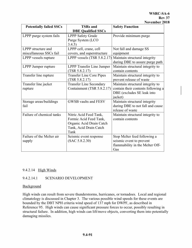
WSRC-SA-6 Rev 37
November 2018
9.4-91
Potentially failed SSCs TSRs and DBE Qualified SSCs
Safety Function
LPPP purge system fails LPPP Safety Grade Purge System (LCO 3.4.5)
Provide minimum purge
LPPP structure and miscellaneous SSCs fail
LPPP cell, crane, cell covers, and superstructure
Not fall and damage SS equipment
LPPP vessels rupture LPPP vessels (TSR 5.8.2.17) Maintain structural integrity during DBE to assure purge path
LPPP Jumper rupture LPPP Transfer Line Jumper (TSR 5.8.2.17)
Maintain structural integrity to contain contents
Transfer line rupture Transfer Line Core Pipes (TSR 5.8.2.17)
Maintain structural integrity to prevent release of waste
Transfer line jacket rupture
Transfer Line Secondary Containment (TSR 5.8.2.17)
Maintain structural integrity to contain their contents following a DBE (excludes SE leak into jacket)
Storage areas/buildings fail
GWSB vaults and FESV Maintain structural integrity during DBE to not fall and cause release of waste
Failure of chemical tanks Nitric Acid Feed Tank, Formic Acid Feed Tank, Organic Acid Drain Catch Tank, Acid Drain Catch Tank
Maintain structural integrity to contain contents
Failure of the Melter air supply
Seismic event response (SAC 5.8.2.30)
Stop Melter feed following a seismic event to prevent flammability in the Melter Off-Gas
9.4.2.14 High Winds
9.4.2.14.1 SCENARIO DEVELOPMENT
Background
High winds can result from severe thunderstorms, hurricanes, or tornadoes. Local and regional climatology is discussed in Chapter 3. The various possible wind speeds for these events are bounded by the DBT NPH criteria wind speed of 137 mph for DWPF, as described in Reference 95. High winds can cause significant pressure forces to occur, possibly resulting in structural failure. In addition, high winds can lift/move objects, converting them into potentially damaging missiles.
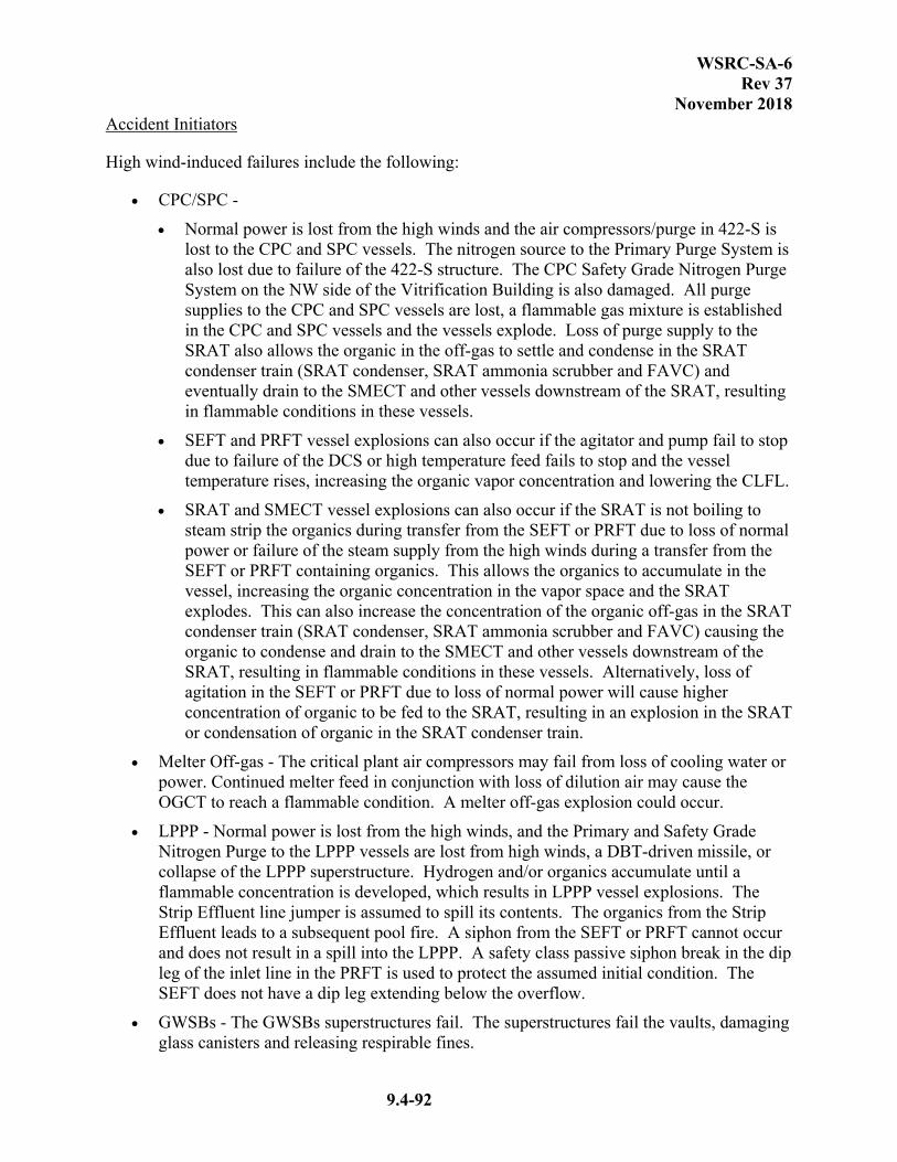
WSRC-SA-6 Rev 37
November 2018
9.4-92
Accident Initiators
High wind-induced failures include the following:
CPC/SPC -
Normal power is lost from the high winds and the air compressors/purge in 422-S is lost to the CPC and SPC vessels. The nitrogen source to the Primary Purge System is also lost due to failure of the 422-S structure. The CPC Safety Grade Nitrogen Purge System on the NW side of the Vitrification Building is also damaged. All purge supplies to the CPC and SPC vessels are lost, a flammable gas mixture is established in the CPC and SPC vessels and the vessels explode. Loss of purge supply to the SRAT also allows the organic in the off-gas to settle and condense in the SRAT condenser train (SRAT condenser, SRAT ammonia scrubber and FAVC) and eventually drain to the SMECT and other vessels downstream of the SRAT, resulting in flammable conditions in these vessels.
SEFT and PRFT vessel explosions can also occur if the agitator and pump fail to stop due to failure of the DCS or high temperature feed fails to stop and the vessel temperature rises, increasing the organic vapor concentration and lowering the CLFL.
SRAT and SMECT vessel explosions can also occur if the SRAT is not boiling to steam strip the organics during transfer from the SEFT or PRFT due to loss of normal power or failure of the steam supply from the high winds during a transfer from the SEFT or PRFT containing organics. This allows the organics to accumulate in the vessel, increasing the organic concentration in the vapor space and the SRAT explodes. This can also increase the concentration of the organic off-gas in the SRAT condenser train (SRAT condenser, SRAT ammonia scrubber and FAVC) causing the organic to condense and drain to the SMECT and other vessels downstream of the SRAT, resulting in flammable conditions in these vessels. Alternatively, loss of agitation in the SEFT or PRFT due to loss of normal power will cause higher concentration of organic to be fed to the SRAT, resulting in an explosion in the SRAT or condensation of organic in the SRAT condenser train.
Melter Off-gas - The critical plant air compressors may fail from loss of cooling water or power. Continued melter feed in conjunction with loss of dilution air may cause the OGCT to reach a flammable condition. A melter off-gas explosion could occur.
LPPP - Normal power is lost from the high winds, and the Primary and Safety Grade Nitrogen Purge to the LPPP vessels are lost from high winds, a DBT-driven missile, or collapse of the LPPP superstructure. Hydrogen and/or organics accumulate until a flammable concentration is developed, which results in LPPP vessel explosions. The Strip Effluent line jumper is assumed to spill its contents. The organics from the Strip Effluent leads to a subsequent pool fire. A siphon from the SEFT or PRFT cannot occur and does not result in a spill into the LPPP. A safety class passive siphon break in the dip leg of the inlet line in the PRFT is used to protect the assumed initial condition. The SEFT does not have a dip leg extending below the overflow.
GWSBs - The GWSBs superstructures fail. The superstructures fail the vaults, damaging glass canisters and releasing respirable fines.

WSRC-SA-6 Rev 37
November 2018
9.4-93
FESV - The gantry crane can fall and fail the FESV, damaging contaminated equipment (e.g., spent melters).
Interarea transfer lines - DBT failures affecting the interarea transfer lines include: rupture of above ground portion of SDP2 during a transfer of Sludge from Tank 40 to the LPPP-SPT, and continued flow through the below grade PCP341, resulting in a spill of 512-S Feed material in 512-S. A core pipe explosion is not credible because the DBT does not create a spark source in the core pipe. A jacket explosion is not considered, since the probability of a core line failure, the jacket being at LFL and tornado event is not credible.
512-S - DBT failures affecting the 512-S include failure of the 512-S PVV leading to deflagrations as discussed in Section 9.4.2.2.
DEWS - The SeaLand (or equivalent) containers fail, resulting in releases from the decontaminated equipment and glass contaminated equipment.
Bounding Unmitigated Scenario
The NPH scenarios assume no abnormal conditions are present at the time of the NPH event occurring (e.g., the vessels are within their respective quiescent times, the Isopar L concentration is within facility limits, the ADPs are within analyzed limits, etc.) without specifically crediting the programs for these initial conditions. These programs are credited in other events that address these abnormal conditions.
The bounding unmitigated scenario is assumed to progress as follows. High winds result in loss of purge to the CPC, SPC, 512-S, and LPPP vessels. This causes the process vessels to detonate in the CPC and SPC, overpressurizing the cell and dislodging the cell covers. The cell covers then fall back into the CPC or other cells, which causes severe damage to the Vitrification Building. Falling debris or structural failure crushes the glass canisters within the Vitrification Building. The SMECT is assumed to contain radioactive material due to SRAT carryover. The SEFT and PRFT are assumed to contain a mixture of Strip Effluent and MST/Sludge Solids due to leakage by the three-way valve. Since organic solvent can be present in the SEFT, PRFT, SRAT and SMECT, the detonation ignites a floating layer of Isopar L that can form on the surface of the liquid leading to a subsequent pool fire in these vessels. The tornado also results in the loss of dilution air to the melter plenum or off-gas allowing excess combustibles to pass to the OGCT causing an explosion in the OGCT. The explosion breaches the melter off-gas system, allowing the heated molten glass in the melter to vent to the cell for 4 days.
In the LPPP, the loss of purge causes the LPPP vessels to detonate. Overpressurization from these detonations dislodges the pump pit cell covers, which then strike the Strip Effluent line which is assumed to be full and a break initiates a siphon to the LPPP from MCU. The organic in the Strip Effluent forms a floating layer of organic solvent in the pump pit, heats up and ignites leading to a pool fire. 512-S fails and results in failure of HEPA filters, deflagration with subsequent liquid entrainment in the LWPT, and detonations with subsequent spills in the LWHT, backpulse tank, and Crossflow Filter as described in 9.4.2.2. A breach of the sludge transfer line to the LPPP-SPT and the 512-S feed transfer to the LWPT fails to be terminated, each resulting in a 15,000 gallon spill. The DEWS SeaLand (or equivalent) containers fail, resulting in releases from the decontaminated equipment and glass contaminated equipment.

WSRC-SA-6 Rev 37
November 2018
9.4-94
The GWSBs collapse, damaging glass canisters stored within, and the FESV is failed, damaging spent melters within. Subsequent releases, unmitigated with no filtration or deposition, continue for 8 hours.
Mitigated Accident Progression
Safety Class Mitigated Scenario
The safety class mitigated scenario is the same as the bounding unmitigated scenario with the exceptions of the transfer line spills, which are prevented.
The passive siphon break on the PRFT inlet dip leg is required as discussed in section 9.4.2.4 and 9.4.2.8 to prevent the potential for a siphon from the PRFT to the LPPP. This is not required to be high winds qualified as it is located inside the Vitrification Building. The Transfer Control Program/Interface Controls will ensure transfers between DWPF and CST and through excavated lines are secured and siphon breaks are established during a tornado warning and following a tornado event. This prevents transfer line spills.
Safety Significant Mitigated Scenario
The safety significant mitigated scenario credits the above controls with the following additional controls.
The first level of control is the Zone 1 Ventilation System to mitigate the consequences from the Vitrification Building by providing a DF of 200 through the sand filter for all releases but from 8 of the crushed canisters. The Vitrification Building, including the RPC Walls, supports the Zone 1 Ventilation System airflow configuration and provides shielding.
A first level of control to prevent an explosion in the CPC/SPC vessels, the Safety Grade Nitrogen Purge System is required to be qualified to perform following a high winds event. In order for this system to provide purge to the vessels following this event, the Vitrification Building must be qualified to maintain its integrity and provide their required safety function following a high winds event. The controls required to support the purge identified in sections 9.4.2.1 Scenario 1 must also continue to function. These controls are not required to be high winds qualified because they are protected by the Vitrification Building.
The Melter Off-Gas Flammability Control Program provides a second level of control which prevents the melter off-gas explosion by ensuring melter feed rate and total melter air flow rate are within specified limits.
For the LPPP, a first level of control is the LPPP Safety Grade Purge System. The LPPP cell, crane, cell covers, and superstructure maintain structural integrity and ensures the LPPP Safety Grade Purge System prevents flammable concentrations from forming in vessels. This prevents the explosion in the LPPP and the spill from the SE jumpers.
In 221-S the Nitric Acid Feed Tank, the Formic Acid Feed Tank, the Organic Acid Drain Catch Tank, and the Acid Drain Catch Tank are SS SSCs and meet the high winds loads. This prevents the release of chemical inventories within 221-S.

WSRC-SA-6 Rev 37
November 2018
9.4-95
The GWSB vaults are classified Safety Significant and are designed to meet wind loading. This prevents their collapse and damage to the canisters.
The FESV is designed to meet the PC-2 wind load criteria which prevents damaging the spent melters.
The Vitrification Building, including the RPC Walls, supports the Zone 1 Ventilation System airflow configuration and provides shielding.
With the above identified controls, the safety significant mitigated scenario is assumed to progress as follows. In the Vitrification Building, the melter off-gas detonates and overpressurizes the cell causing debris or cell covers to fall back into the cell or other cell. This results in a loss of vessel purge flow causing the remaining process vessels in the CPC and SPC to detonate. Since organic solvent can be present in the SEFT, PRFT, SRAT, and SMECT, the detonation ignites a floating layer of organic (Isopar L) that can form on the surface of the liquid leading to a subsequent pool fire in the vessels. Falling debris crushes the canister with the Vitrification Building. In the melt cell, the falling debris or cell covers breach the melter off-gas system allowing a release to the cell for 4 days. The 512-S fails and results in failure of HEPA filters, deflagration with subsequent liquid entrainment in the LWPT, and detonations with subsequent spills in the LWHT, backpulse tank, and crossflow filter as described in 9.4.2.2. The DEWS SeaLand (or equivalent) containers fail, resulting in releases from the decontaminated equipment and glass contaminated equipment.
9.4.2.14.2 FREQUENCY DETERMINATION
The frequency of this scenario is extremely unlikely (Ref. 95).
9.4.2.14.3 SOURCE TERM ANALYSIS
Bounding Unmitigated Scenario
Vessel detonation radiological source terms were calculated for the OGCT, SEFT, SRAT, SME, SMECT, MFT, PRFT, RCT and DWTT in References 124, 198, and 214. In addition, a source term was developed for the volume of Melter off-gas that would be present in the OGCT at the time of the explosion (Ref. 214). A subsequent fire source term was calculated for the SEFT, SRAT, SMECT and PRFT due to the formation of an organic pool (Isopar L) in Reference 124. A source term was calculated for the release of respirable fines of glass from the crushed canisters in Reference 129. An off-gas source term was calculated for the glass melter in Reference 128. Since Zone 1 ventilation has failed and the Vitrification Building is assumed to have failed, no filtration or deposition is assumed. Therefore, the total source term release to the environment is the same as the release to the building.
The source term for the15,000 gallon sludge transfer line spill event and 15,000 gallon 512-S feed overflow event was derived (Ref. 126) based on above grade transfer line spills, assuming a spill source term and total duration of 8 hours for resuspension. Radiological source term associated with failure of LPPP is based on concurrent explosions in the LPPP vessels (Ref. 124 and 214). A spill source term was developed for the Strip Effluent line in Reference 126 and a subsequent pool fire source term was calculated from the organic spilled in the LPPP in References 124 and 133.

WSRC-SA-6 Rev 37
November 2018
9.4-96
Radiological source terms for the FESV and glass canisters damaged in the GWSB #1 and GWSB #2 collapse were calculated in Reference 129. For DEWS, DBE source terms calculated in References 159 and 197 were used because they bound the DBT source terms. The source term associated with failure of 512-S is based on the failure of HEPA filters, deflagration with subsequent liquid entrainment in the LWPT, and detonations with subsequent spills in the LWHT, backpulse tank, and crossflow filter as described in Section 9.4.2.2 (Ref. 125).
Process inventory chemical source terms were calculated per the screening analyses as described in Section 9.4.1.2.
Safety Class Mitigated Scenario
The source term to the offsite receptor for the safety class mitigated scenario is the same as the bounding unmitigated scenario except the transfer line spills are prevented, thus not included.
The following feed vessels in the Vitrification Building are assumed to fail by high winds:
Vitrification Building - 3rd Level
- Process frit slurry feed vessel
- Catalyst feed vessel
- 90% formic acid feed vessel
- Nitric acid feed vessel
- Sodium nitrite feed vessel
- Caustic feed vessel
- Off-gas chemical feed vessel
- Additive mix/feed vessel
Vitrification Building - Tunnel Level
- Floor drain catch vessel
- Acid drain catch vessel
- Organic acid catch vessel
Vitrification Building - 1st Level
- Nitric acid decon feed vessel
- Oxalic acid decon feed vessel
Vitrification Building - Mez. Level
- Nitric acid dilution vessel

WSRC-SA-6 Rev 37
November 2018
9.4-97
Upon their failure, the aforementioned vessels spill their entire contents. The dikes surrounding the vessels are also failed, thus allowing the spilled inventories to form unmitigated pools. If sodium nitrite, nitric acid and formic acid inventories are assumed to remain unmixed, they will evaporate. If they are assumed to mix, the resulting chemical reaction will produce oxides of nitrogen. Both the unmixed and mixed cases are evaluated to determine the bounding consequence (see Table 9.1-3). Since no energetic events (explosions) are postulated to occur in these areas, no release mechanisms are associated with the remaining inventories (all nonvolatile liquids or solids).
Process inventory chemical source terms were calculated per the screening analyses described in Section 9.4.1.2.
Safety Significant Mitigated Scenario
In the Vitrification Building, the source terms associated with a melter off-gas detonation, CPC and SPC process vessel detonations, pool fires (in the SEFT, PRFT, SRAT, and SMECT), 4-day melter off-gas release, and the release of respirable fines of glass from crushed canisters are the same as those described above for the unmitigated scenario. The Zone 1 Ventilation System is assumed to function in the safety significant mitigated scenario and provide a DF of 200 for releases within the canyon except for fines from up to 8 of the crushed canisters.
The source term associated with failure of the 512-S and DEWS are the same as those described above for the unmitigated scenario.
9.4.2.14.4 CONSEQUENCE ANALYSIS
Bounding Unmitigated Scenario
With the largest contribution from a ground level Vitrification Building release location, the maximally exposed offsite individual would receive a dose of less than 5 rem from the bounding unmitigated scenario (Ref. 214). This is based on doses from the following contributors: Vitrification Building, Transfer Lines, LPPP, FESV, GWSB #1, GWSB #2, 512-S, and DEWS. The onsite receptor would receive a dose of greater than 100 rem based on these same releases (Ref. 214).
Screening analyses have shown that process inventory chemical source terms will not yield consequences that exceed the offsite acceptance criteria (see Section 9.4.1.2).
Table 9.1-3 contains offsite chemical concentrations associated with the chemical releases discussed above. Except where noted in the table, peak 15-minute average concentrations are reported.
Safety Class Mitigated Scenario
With the largest contribution from a ground level LPPP release location, the maximally exposed offsite individual would receive a dose of less than 4 rem from the mitigated radiological accident scenario, which includes: failure of the Vitrification Building, FESV, GWSB #1, GWSB #2, 512-S, DEWS, and LPPP (Ref. 214).
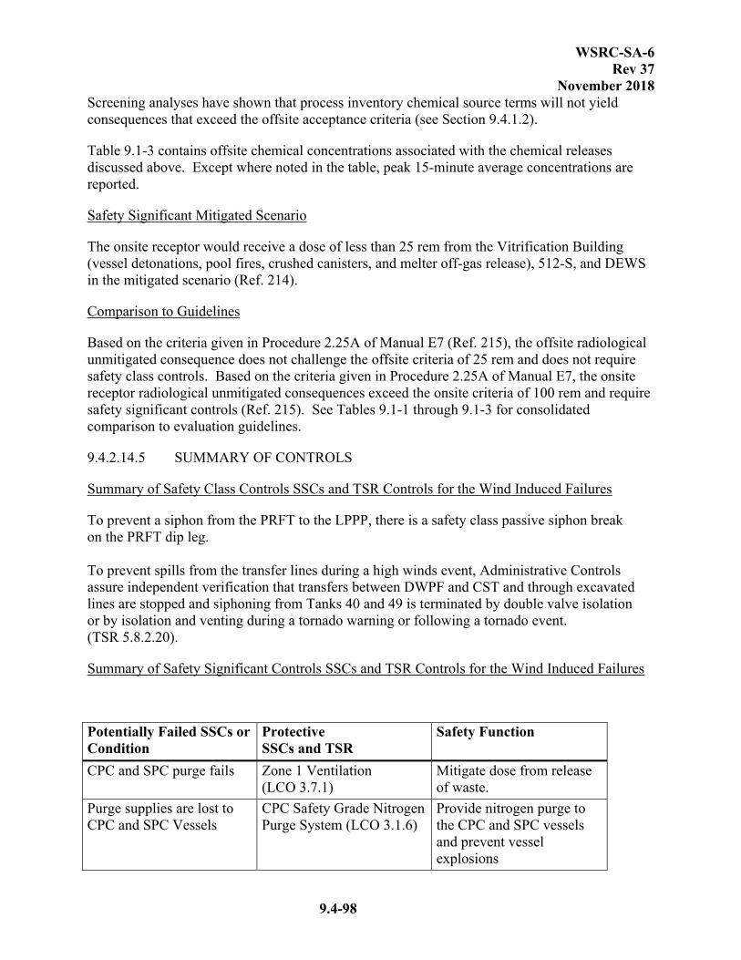
WSRC-SA-6 Rev 37
November 2018
9.4-98
Screening analyses have shown that process inventory chemical source terms will not yield consequences that exceed the offsite acceptance criteria (see Section 9.4.1.2).
Table 9.1-3 contains offsite chemical concentrations associated with the chemical releases discussed above. Except where noted in the table, peak 15-minute average concentrations are reported.
Safety Significant Mitigated Scenario
The onsite receptor would receive a dose of less than 25 rem from the Vitrification Building (vessel detonations, pool fires, crushed canisters, and melter off-gas release), 512-S, and DEWS in the mitigated scenario (Ref. 214).
Comparison to Guidelines
Based on the criteria given in Procedure 2.25A of Manual E7 (Ref. 215), the offsite radiological unmitigated consequence does not challenge the offsite criteria of 25 rem and does not require safety class controls. Based on the criteria given in Procedure 2.25A of Manual E7, the onsite receptor radiological unmitigated consequences exceed the onsite criteria of 100 rem and require safety significant controls (Ref. 215). See Tables 9.1-1 through 9.1-3 for consolidated comparison to evaluation guidelines.
9.4.2.14.5 SUMMARY OF CONTROLS
Summary of Safety Class Controls SSCs and TSR Controls for the Wind Induced Failures
To prevent a siphon from the PRFT to the LPPP, there is a safety class passive siphon break on the PRFT dip leg. To prevent spills from the transfer lines during a high winds event, Administrative Controls assure independent verification that transfers between DWPF and CST and through excavated lines are stopped and siphoning from Tanks 40 and 49 is terminated by double valve isolation or by isolation and venting during a tornado warning or following a tornado event. (TSR 5.8.2.20).
Summary of Safety Significant Controls SSCs and TSR Controls for the Wind Induced Failures
Potentially Failed SSCs or Condition
Protective SSCs and TSR
Safety Function
CPC and SPC purge fails Zone 1 Ventilation (LCO 3.7.1)
Mitigate dose from release of waste.
Purge supplies are lost to CPC and SPC Vessels
CPC Safety Grade Nitrogen Purge System (LCO 3.1.6)
Provide nitrogen purge to the CPC and SPC vessels and prevent vessel explosions
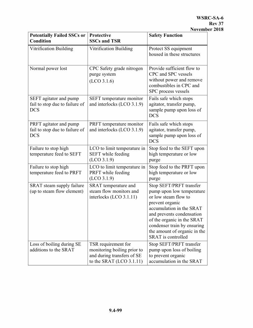
WSRC-SA-6 Rev 37
November 2018
9.4-99
Potentially Failed SSCs or Condition
Protective SSCs and TSR
Safety Function
Vitrification Building Vitrification Building
Protect SS equipment housed in these structures
Normal power lost CPC Safety grade nitrogen purge system
(LCO 3.1.6)
Provide sufficient flow to CPC and SPC vessels without power and remove combustibles in CPC and SPC process vessels
SEFT agitator and pump fail to stop due to failure of DCS
SEFT temperature monitor and interlocks (LCO 3.1.9)
Fails safe which stops agitator, transfer pump, sample pump upon loss of DCS
PRFT agitator and pump fail to stop due to failure of DCS
PRFT temperature monitor and interlocks (LCO 3.1.9)
Fails safe which stops agitator, transfer pump, sample pump upon loss of DCS
Failure to stop high temperature feed to SEFT
LCO to limit temperature in SEFT while feeding (LCO 3.1.9)
Stop feed to the SEFT upon high temperature or low purge
Failure to stop high temperature feed to PRFT
LCO to limit temperature in PRFT while feeding (LCO 3.1.9)
Stop feed to the PRFT upon high temperature or low purge
SRAT steam supply failure (up to steam flow element)
SRAT temperature and steam flow monitors and interlocks (LCO 3.1.11)
Stop SEFT/PRFT transfer pump upon low temperature or low steam flow to prevent organic accumulation in the SRAT and prevents condensation of the organic in the SRAT condenser train by ensuring the amount of organic in the SRAT is controlled
Loss of boiling during SE additions to the SRAT
TSR requirement for monitoring boiling prior to and during transfers of SE to the SRAT (LCO 3.1.11)
Stop SEFT/PRFT transfer pump upon loss of boiling to prevent organic accumulation in the SRAT
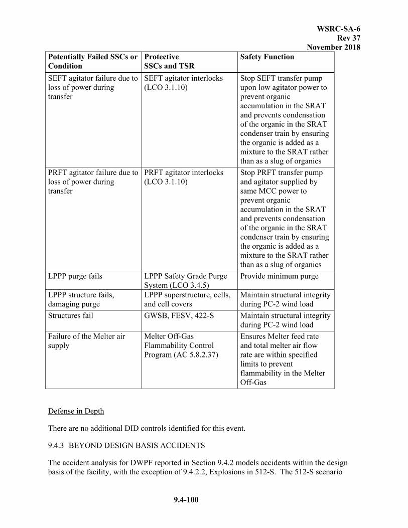
WSRC-SA-6 Rev 37
November 2018
9.4-100
Potentially Failed SSCs or Condition
Protective SSCs and TSR
Safety Function
SEFT agitator failure due to loss of power during transfer
SEFT agitator interlocks (LCO 3.1.10)
Stop SEFT transfer pump upon low agitator power to prevent organic accumulation in the SRAT and prevents condensation of the organic in the SRAT condenser train by ensuring the organic is added as a mixture to the SRAT rather than as a slug of organics
PRFT agitator failure due to loss of power during transfer
PRFT agitator interlocks (LCO 3.1.10)
Stop PRFT transfer pump and agitator supplied by same MCC power to prevent organic accumulation in the SRAT and prevents condensation of the organic in the SRAT condenser train by ensuring the organic is added as a mixture to the SRAT rather than as a slug of organics
LPPP purge fails LPPP Safety Grade Purge System (LCO 3.4.5)
Provide minimum purge
LPPP structure fails, damaging purge
LPPP superstructure, cells, and cell covers
Maintain structural integrity during PC-2 wind load
Structures fail GWSB, FESV, 422-S Maintain structural integrity during PC-2 wind load
Failure of the Melter air supply
Melter Off-Gas Flammability Control Program (AC 5.8.2.37)
Ensures Melter feed rate and total melter air flow rate are within specified limits to prevent flammability in the Melter Off-Gas
Defense in Depth
There are no additional DID controls identified for this event.
9.4.3 BEYOND DESIGN BASIS ACCIDENTS
The accident analysis for DWPF reported in Section 9.4.2 models accidents within the design basis of the facility, with the exception of 9.4.2.2, Explosions in 512-S. The 512-S scenario

WSRC-SA-6 Rev 37
November 2018
9.4-101
could be considered beyond design basis, based on a qualitative assessment of prerequisite conditions. The design basis for internally initiated events is defined by the credibility threshold; i.e., any event initiated by internal mechanisms that has a calculated frequency of occurrence
greater than or equal to 1.0E-06 yr-1. For natural phenomena (earthquakes, high winds, etc.), the design basis is defined by two criteria. First, the event must have a calculated frequency of occurrence above the credibility threshold. The second criterion is based on the fact that each type of natural phenomena has an assigned design basis severity; any modeled natural phenomena-initiated event must have an initiator severity not in excess of the design basis value. For example, for seismic events, the design basis Peak Ground Acceleration (PGA) is 0.18g (0.20g is used in the accident analyses); any seismic event occurring with a PGA greater than 0.18g is defined to be beyond the design basis of the facility and is not explicitly modeled in the accident analysis, per Section 9.4.2.
However, it is desirable to perform a summary examination of those accidents, both internal and natural phenomena-initiated, that exist beyond the design basis. This examination provides assurance that there are no events that lie just beyond the design basis that possess unacceptable, or dramatically higher, consequences than those sequences modeled in Section 9.4.2. Therefore, the following two sections examine the radiological and chemical consequences associated with BDBAs for DWPF. The following sections do not evaluate the consequences due to a SMECT explosion, since the probability of a seismic event, system failures, and a carryover of radioactive materials to the SMECT is well below the credibility threshold.
9.4.3.1 Beyond Design Basis Accidents - Radiological Consequences
Vitrification Building and NPH
Note: The following information is based on the original DWPF design that included salt processing utilizing a precipitate stream. The precipitate stream has been eliminated. The DWPF currently utilizes a coupled operation with sludge (including ARP) and Strip Effluent waste streams. The design basis accident analysis performed to support sludge (including ARP) and Strip Effluent coupled operation resulted in large reductions in the DBA consequences. Additionally, effects of ADPs and IDP restrictions are not reflected. Therefore, the following discussions should be treated as historical information.
The PSA for DWPF examined thousands of accidents, many of which have frequencies below
the credibility threshold of 1.0E-06 yr-1 (Ref. 1). For accidents above specific frequency truncation limits that vary for each plant damage state, source terms and estimated consequences were calculated. A closer examination of the bounding BDBAs due to internal and seismic initiators follows.
The BDBA evaluation was constructed to address primarily those accidents using the PSA (Ref. 1) with a frequency range of 1E-06 to 1E-08/year. The bounding unmitigated scenarios described in the previous sections have event frequencies below 1E-09/year and are not included in this section.
WSRC-SA-6 Rev 37
November 2018
9.4-102
For internal energetic events, approximately 150 accident sequences had frequencies that were
within one-half decade below the credibility threshold (i.e., frequencies > 5E-07 yr-1). None of these accidents, however, had offsite consequences greater than those calculated for the bounding credible internal event described in the PSA (i.e., 2.39 rem from the SPC Explosion).
For 0.1g and 0.2g earthquakes, approximately 180 accident sequences had frequencies that were
within one decade below the credibility threshold (i.e., frequencies > 1E-07 yr-1). Of these accidents, the bounding consequence sequence has an offsite EDE of 4.02 rem, and a frequency
of 1.66E-07 yr-1. This accident sequence, initiated by an earthquake at 0.2g acceleration, corresponds to deflagrations in the PR and PRFT that lead to the spilling of the RCT, and a deflagration and fire in the SPC. During this event, the cell covers for the SPC and CPC have failed, the Vitrification Building ventilation has failed, the LPPP building has been breached, the LPPP ventilation has failed, and the melter off-gas system has lost integrity and is releasing off-gas. However, although this is the bounding 0.1g or 0.2g seismic event within one decade below the credibility threshold and higher, the consequences are still below the radiological acceptance
criteria at 1E-06 yr-1, 25 rem.
For all modeled PGAs (0.1g to 0.6g), approximately 370 accident sequences had frequencies that were within one or one-half decade below the credibility threshold (i.e., frequencies > 1E-07 or
5E-07 yr-1, see the PSA. The resulting initiator frequencies are presented in the PSA (Ref. 1).
Of the seismic accidents modeled, the bounding consequence sequence has an offsite EDE of
8.43 rem, and a frequency of 1.58E-07 yr-1. This accident sequence, initiated by an earthquake at 0.6g acceleration, corresponds to deflagrations in the PPT, PR, PRFT, PRBT, SME, SRAT, and MFT that lead to venting of the RCT, and a deflagration and fire in the SPC. During this event, the cell covers for the SPC and CPC have failed, the Vitrification Building has collapsed seismically, the LPPP building has been breached, the LPPP ventilation has failed, and the melter off-gas system has lost integrity and is releasing off-gas. However, although this is the bounding 0.1g to 0.6g seismic event within one or one-half decade below the credibility threshold and higher, the consequences are still below the radiological acceptance criteria at
1E-06 yr-1, 25 rem.
For credible seismic events initiated by beyond design basis PGAs (0.3g to 0.6g), the bounding
consequence sequence has an offsite EDE of 6.02 rem, and a frequency of 1.23E-06 yr-1. This accident sequence, initiated by an earthquake at 0.3g acceleration, corresponds to deflagrations in the PR, PRFT, PRBT, SME, SRAT, and MFT that lead to venting of the RCT, and a deflagration and fire in the SPC. During this event, the cell covers for the SPC and CPC have failed, the Vitrification Building ventilation has failed, the LPPP building has been breached, the LPPP ventilation has failed, and the melter off-gas system has lost integrity and is releasing off-
gas. The consequences are below the radiological acceptance criteria at 1.0E-06 yr-1, 25 rem.
Large Liquid Waste Release
A large liquid waste release (i.e., greater than 15,000 gallons spilled material) is not a credible event for the DWPF waste streams. This event is included as a BDBA to ensure that SC controls
WSRC-SA-6 Rev 37
November 2018
9.4-103
are not required and the selected SS controls are adequate to mitigate a large spill from an interarea transfer error assuming the selected SS controls function.
The BDBA large liquid release scenario is assumed to result in 1.3 million gallons of sludge being released from primary containment to above ground in eight hours. This is a result from a breach of a transfer line. The sludge is limited to 1.3 million gallons because this volume is the maximum capacity of the waste tank in the tank farms. The inhalation dose potential of this assumed quantity of sludge is sufficiently bounding such that no additional salt solution need be considered. Section 9.4.2.9 addresses the impact of releasing 15,000 gallons of sludge above ground.
The consequences of the BDBA large liquid waste release were calculated by conservatively extrapolating the consequences from the 15,000 gallons above-ground spill of sludge at LPPP of 0.21 rem (Ref. 126) to 1.3 million gallons. This results in an Offsite dose of 18 rem. This release is considered to be a BEU event.
This BDBA bounds the credible scenarios discussed in Section 9.4.2.9. The difference between the large liquid waste release and the assumed Interarea Transfer Line event is the amount of material released to the environment. The consequence from this size spill does not exceed the Offsite EGs (this is the same result as for the 15,000 gallon spill size evaluated in Section 9.4.2.9). However, this event is precluded by the existing control, Transfer Control Program and Interface Controls. Therefore, no new controls are necessary.
Assuming the SS core pipe performs its function of waste confinement, the other Transfer Error event that could result in a release outside of primary containment would be the overflow of a pump tank (the bounding location being the SPT in the LPPP). The current analysis in DSA Section 9.4.2.9 also assumes 15,000 gallon spill for this scenario. However, TSR Administrative Controls identified in section 11.7.2.2 prevent a vessel overflow. Therefore, no new controls are necessary.
Thus, as shown above, no new SC controls are warranted and the controls identified in Section 9.4.2 are adequate to address large liquid releases. This BDBA also bounds the credible scenarios discussed in Section 9.4.2.9. The differences between the large liquid waste release due to overflow and the assumed leak/spill in the LPPP is the amount of material released to the environment. The consequences from a 1.3 million gallon sludge spill (which bounds a 1.3 million gallon bounding ARP salt solution spill) would not exceed the Offsite EGs. Therefore, no new controls are necessary.
Therefore, based on the consequences and discussions above, BDBAs for DWPF can involve radiological consequences greater than those due to the SC mitigated scenarios reported in Section 9.4.2. However, even in these cases, the radiological consequences are still below the radiological acceptance criteria.
9.4.3.2 Beyond Design Basis Accidents - Chemical Consequences
The BDBAs discussed in the previous section have chemical, as well as radiological consequences. Rather than consider BDBA chemical consequences on an accident initiator

WSRC-SA-6 Rev 37
November 2018
9.4-104
basis, this section examines them from an inventory (process, feed, and benzene; as per Section 9.4.1.2) standpoint.
Screening analyses have shown that bounding process inventory chemical source terms will not yield consequences that challenge the offsite EGs. In the accident analyses, the offsite bounding chemical consequences from feed inventory source terms have been shown to not challenge the offsite EGs. Similarly, the bounding offsite chemical consequences from benzene source terms also do not challenge the offsite EGs. Therefore, since no bounding chemical consequence from the chemical inventories in the main accident analysis challenge the EGs, the same would be true when these bounding consequences are associated with BDBA events.

WSRC-SA-6 Rev 37
November 2018
9.5-1
9.5 REFERENCES
1. Gough, S.T. DWPF Mode C Probabilistic Safety Analysis. WSRC-TR-95-0198, June 1995.
2. Defense in Depth Evaluation for the Defense Waste Processing Facility and Late Wash Facility (U). WSRC-TR-94-0597, Rev. 0.
3. Conduct of Engineering and Technical Support. WSRC E7 Manual, Procedure 2.25, “Functional Classification,” Rev. 3.
4. Townsend, J.D. Safety Class and Safety Significant Final Functional Classification Report for the DWPF. WSRC-TR-95-00189, Rev. 0.
5. Blanton, C.H. Defense Waste Processing Facility Preliminary Hazards Analysis (U). WSRC-TR-94-0586, Rev. 0.
6. Preparation Guide for U.S. Department of Energy Nonreactor Nuclear Facility Safety Analysis Reports. DOE Standard DOE-STD-3009-94. U.S. Department of Energy, Washington, DC, July 1994 and Change Notice No. 1 (January 2000), 2 (April 2002), and 3 (March 2006).
7. Deleted.
8. Schwenker, J.P. Resolution of DWPF’s Safety Basis (U). WSRC-TR-94-0395.
9. Kalinich, D.A. and Garrett, R.J. Analysis to Support Selection of Safety Equipment for the Defense Waste Processing Facility (U). WSRC-TR-94-0447, Rev. 0.
10. Huang, J.C. Application of Screening Methodology for Selecting Important Chemicals for Inclusion in the DWPF SAR Accident Consequence Analysis (U). S-CLC-S-00012, Rev. 0.
11. Kalinich, D.A. Screening of DWPF Process Inventory Chemicals (U). M-CLC-S-00463, Rev. 1.
12. Nuclear Safety Analysis Reports. DOE Order 5480.23, U.S. Department of Energy, Washington, DC, 1992.
13. Technical Safety Requirements. DOE Order 5480.22, U.S. Department of Energy, Washington, DC, February 1992.
14. Hazard Categorization and Accident Analysis Techniques for Compliance with DOE Order 5480.23. Nuclear Safety Analysis Reports. DOE- STD-1027-92. U.S. Department of Energy, Washington, DC, 1992.
15. DOE Standard Guidance for Preparation of DOE 5480.22 (TSR) and DOE 5480.23 (SAR) Implementation Plans. DOE- STD-3011-94, U.S. Department of Energy, Washington, DC, 1994.

WSRC-SA-6 Rev 37
November 2018
9.5-2
16. Deleted.
17. Atmospheric Dispersion Models for Potential Accident Consequence Assessments at Nuclear Power Plants. Regulatory Guide 1.145, U.S. Nuclear Regulatory Commission, Washington, DC, Rev. 1.
18. Calculation of Annual Doses to Man from Routine Releases of Reactor Effluents for the Purpose of Evaluating Compliance with 10 CFR Part 50, Appendix I. Regulatory Guide 1.109, U.S. Nuclear Regulatory Commission, Washington, DC, Rev. 1.
19. Deleted.
20. Hazard Baseline Documentation. DOE-EM-STD-5502-94, U.S. Department of Energy, Washington, DC, 1994.
21. Schornhorst, J.R. Defense Waste Processing Facility, Hazards Assessment: NPSR Report. SRT-WAG-920079, 1992.
22. Fire Hazard Analysis for DWPF Building 221-S (Vitrification Bldg.). F-FHA-S-00008, Rev. 3.
23. Deleted.
24. Fire Hazards Analysis for 260-S Failed Equipment Storage Vault and Associated Control Building. M-FHA-S-00012, Rev. 2.
25. Fire Hazards Analysis for Glass Waste Storage Building (250-S). M-FHA-S-00004, Rev. 2.
26. Fire Hazards Analysis for the Defense Waste Processing Facility Building 251-S (U). M-FHA-S-00014, Rev. 4.
27. Deleted.
28a. Fire Hazard Analysis for DWPF Low Point Pump Pit Facility, Building 511-S. F-FHA-S-00010, Rev. 2.
28b. Fire Hazard Analysis for 512-S. F-FHA-S-00012, Rev. 2.
29. Process Hazards Review Program Final Report: Defense Waste Processing Facility, Sludge Plant, Saltstone, and NWTF. S-1780/S-3122 Vol. 1. Bechtel National, Inc., San Francisco, CA, 1986.
30. Sarrack, A. G. Interarea Transfer Line Explosion Frequency. S-CLC-G-00134, Rev. 0.
31. Westinghouse Savannah River Company Facility Safety Analysis Manual. Manual 9Q, Rev. 2 (this manual is superseded by Manual 11Q Ref. 148).
WSRC-SA-6 Rev 37
November 2018
9.5-3
32. Safety Analysis - 200-S Area Savannah River Site Defense Waste Processing Facility Operation (U). DPSTSA-200-10 SUP-20, Rev. 8.
33. Sarrack, A.G. DWPF Crane Load Drop Frequency (U). S-CLC-S-00076, Rev. 0.
34. Deleted.
35. Radiological Control Manual. Manual 5Q.
36. Ford, H.A. Industrial Hazard Event Frequency Estimates for the DWPF SAR (U). S-CLC-S-00014. Rev. 0.
37. Deleted.
38. Weber, J.H. Statistical Analysis of Frequency of DWPF Accident Scenarios (U). WSRC-TR-93-335.
39. Fire Protection Program Manual. Manual 2Q.
40. S-Area Fire Control Preplan Manual. Manual 2Q2-4-S.
41. Missile Impact from DWPF Process Tank Agitator Blades (U). SRT-MTS-955147 Daughterty, W.L. to Gee, J.T.
42. Deleted.
43. Savannah River Site Basic Data for the Defense Waste Processing Facility. DPSP-80-1033, Curie Balance, Rev. 91, E. I. du Pont de Nemours & Co., Savannah River Site, Aiken, SC, December 1984.
44. Gough, S.T. Input Parameters for DWPFAST and S-Area DWPFASTXL. N-CLC-S-00011, Rev. 0.
45. Deleted.
46. Deleted.
47. Deleted.
48. Deleted.
49. Deleted.
50. Deleted.
51. Deleted.
52. Lewis, B. and von Elbe, G. Combustion, Flames and Explosions of Gases. Third Edition, Academic Press, Inc., Orlando, 1987.

WSRC-SA-6 Rev 37
November 2018
9.5-4
53. Deleted.
54. Deleted.
55. Deleted.
56. Kalinich, D.A. DWPF NSI Analysis - Unmitigated Release. M-CLC-S-00326, Rev. 0.
57. Deleted.
58. Deleted.
59. Deleted.
60. Deleted.
61. Deleted.
62. Deleted.
63. Deleted.
64. Durant, W.S. Perkins, W.C. and Severynse, T.F. System Analysis - 200 Area, Savannah River Plant, F-Canyon Operations. DPSTSY-200-1F, Volume 2, December 1983.
65. Deleted.
66. Kalinich, D.A. Technical Basis for the Defense Waste Processing Facility Vitrification Building DF. SRT-LWA-94-9001, February 1994.
67. Lee, M.W. and Prout, W.E. Statistical Analysis of Sand Filter Efficiency. DPST-79-506, September 1979.
68. Material Balance Tables for the DWPF Coupled Feed Flowsheet with Batch One Sludge (U). WSRC-TR-93-203, Rev. 0.
69. Nguyen, B.V. DWPF Chemical Inventory (U). X-CLC-S-00010, Rev. 0.
70. Incropera, F.P. and DeWitt, D.P. Fundamentals of Heat and Mass Transfer. 2nd Ed., John Wiley & Sons, Inc., New York, 1985.
71. Craig, D.K. Toxic Chemical Hazard Classification and Risk Acceptance Guidelines for Use in DOE Facilities (U). WSRC-MS-92-00206, Rev 2.
72. DiNenno, P.J. SFPE Handbook of Fire Protection Engineering, 1st ed. NFPA, Quincy, MA, 1988.

WSRC-SA-6 Rev 37
November 2018
9.5-5
73. Long, T.A. Source Term due to Possible Formic Acid-Nitric Acid Interactions Following a Seismic Event (U). M-CLC-S-00398, Rev. 0.
74. Kalinich, D. A. DWPF Functional Classification Analysis - Evaluation of Safety Class and Safety Significant Functions with Respect to Chemical Releases. M-CLC-S-00412, Rev. 1.
75. Deleted.
76. Deleted.
77. Deleted.
78. Deleted.
79. Deleted.
80. “Areal Locations of Hazardous Atmospheres User’s Manual.” Computer-Aided Management of Emergency Operations. October 1992.
81. Palazzi, E. Atmospheric Environment. Vol. 16, No. 12, pp. 2785-2790, “Diffusion From a Steady Source of Short Duration,” 1982.
82. Spicer, T. and Havens, J. Users Guide for the DEGADIS 2.1 Dense Gas Dispersion Model, Cincinnati: U.S. Environmental Protection Agency. EPA-450/4-89-019, 1989.
83. Hanna, S.R. Handbook on Atmospheric Diffusion. DOE/TIC-11223, Atmospheric Turbulence and Diffusion Laboratory National Oceanic and Atmospheric Administration, Technical Information Center U.S. Department of Energy, 1982.
84. Deleted.
85. Gough, S. T. DWPF Mode C Accident Selection (U). N-CLC-S-00025, Rev. 0.
86. Mangiante, W.R. and Valentine, M.G. DWPF Accident Analysis Ammonium Nitrate Study (U). WSRC-TR-94-0595, Rev. 0.
87. Sarrack, A.G. Natural Hazards with Negligible Risk to DWPF (U). S-CLC-S-00057, Rev. 0.
88. Gough, S.T. Unmitigated DWPF MODE C Accident Analysis (U). N-CLC-S-00044, Rev. 1.
89. Gough, S.T. DWPF Mode C Bounding Accident Analysis (U). N-CLC-S-00028, Rev. 0.
90. Deleted.
91. Deleted.

WSRC-SA-6 Rev 37
November 2018
9.5-6
92. Kalinich, D.A. Evaluation Of Postulated Interarea Transfer Accident at the DWPF (U). M-CLC-S-00556, Rev. 0.
93. Deleted.
94. Deleted.
95. Natural Phenomena Hazards Design and Evaluation Criteria for Department of Energy Facilities. DOE-STD-1020-94, DOE Standard, April 1994.
96. Deleted.
97. Sarrack, A.G. Airplane Crash Frequency for DWPF Structures (U). S-CLC-S-00038, Rev. 0.
98. Lux, C. R. Helicopter Crash Frequency for DWPF (U). S-CLC-S-00039, Rev. 1.
99. Sarrack, A.G. Train Accident Frequency Data for the DWPF Safety Analysis Report (U). S-CLC-S-00026, Rev. 0.
100. Hopkins, R. C. Engineering Position on Batch 1 Sludge Only Operation and Ammonium Nitrate Deposition (U). OPS-DTG-960040, February 1996.
101. Deleted.
102. Deleted.
103. Deleted.
104. Deleted.
105. Deleted.
106. Deleted.
107. Deleted.
108. Deleted.
109. Gehr, D.F. DWPF Non-Safety Class / Safety Significant Defense-In-Depth Evaluation (U). WSRC-TR-98-00399, March 1999.
110. Deleted.
111. Deleted.
112. Natural Phenomena Hazards Performance Categorization Criteria for Structures, Systems and Components. DOE-STD-1021-93, DOE Standard.

WSRC-SA-6 Rev 37
November 2018
9.5-7
113. Deleted.
114. Areal Locations of Hazardous Atmospheres (ALOHA). Version 5.1, National Oceanic and Atmospheric Administration of the US EPA.
115. Deleted.
116. Deleted.
117. Deleted.
118. Hang, P. Consequence Analysis of S-Area Nitrogen Dioxide Releases (U). S-CLC-S-00086, Rev. 0.
119. DWPF Safety Analyses Input Deck, http://pceweb.srs.gov/Inputdeck.
120. 512-S Facility Consolidated Hazard Analysis (U). WSRC-TR-2002-00223, Rev. 6.
121. Elder, H. DWPF Revised Curie Balance. N-CLC-S-00060, Rev. 5.
122. Drumm, M. D. Radionuclide Inventories of the Actinide Removal Process for the Consolidated Hazards Assessment Process. X-CLC-S-00126, Rev. 2.
123. Airborne Release Fractions/Rates and Respirable Fractions for Nonreactor Nuclear Facilities. DOE-HDBK-3010-94, December 1994.
124. Klotz, W. Vessel and Pool Fire Hydrogen/Isopar L Explosion Accident Analysis for ARP, MCU and DWPF Sludge Only Operations (U). S-CLC-S-00101, Rev. 1.
125. Yeung, R. 512-S Facility Consolidated Hazard Analysis Process (CHAP) Basis (U). S-CLC-S-00104, Rev. 1.
126. Thoman, D. ARP/DWPF with MCU-SE Coupled Operations Leaks and Spills (U). S-CLC-S-00102, Rev. 2.
127. Deleted.
128. Sum, E. DWPF Melter Steam Explosion, Spill, and Off-gas Doses (U). S-CLC-S-00105, Rev. 1.
129. Yeager, T. DWPF Natural Phenomena Consequences, Earthquake and Tornado (U). S-CLC-S-00106, Rev. 4.
130. Deleted.
131. Deleted.
132. Conduct of Engineering and Technical Support. WSRC E7 Manual, Procedure 2.25, “Functional Classification,” Rev. 13.

WSRC-SA-6 Rev 37
November 2018
9.5-8
133. Eigenbrot, N. J. Explosions in ARP/DWPF Process Cells (U). S-CLC-S-00103, Rev. 4.
134. Deleted.
135. MACCS2 Computer Code Application Guidance for Documented Safety Analysis. DOE-EH-4.2.1.3-Final MACCS2 Code Guidance, Final Report, U.S. Department of Energy, Washington, DC, June 2004.
136. Deleted.
137. Deleted.
138. Eckerman, K.F. (1993) and Ryman, J.C. External Exposure to Radionuclides in Air, Water, and Soil. Federal Guidance Report 12. EPA 402-R-93-081, U.S. Environmental Protection Agency, Washington, DC.
139. “Human Respiratory Tract Model for Radiological Protection,” Annals of the ICRP. ICRP (1994), ICRP Publication 66 Volume 24, Numbers 1-4 Pergamon Press, New York, NY.
140. “Dose Coefficients for Intakes of Radionuclides by Workers: A Report of a Task Group of Committee 2 of the International Commission on Radiological Protection Replacement of ICRP Publication 61,” Annals of the ICRP. ICRP Publication 68, ICRP (1995). Volume 24, Number 2, Pergamon Press, New York, NY.
141. “Age-dependent Doses to the Members of the Public from Intake of Radionuclides: Part 5,” Annals of the ICRP. ICRP (1996a), ICRP Publication 72, Volume 26, Number 1, Pergamon Press, New York, NY.
142. The ICRP Database of Dose Coefficients: Workers and Members of the Public, Version 1. ICRP (1999), Pergamon Press, New York, NY.
143. “Age-dependent Doses to the Members of the Public from Intake of Radionuclides: Part 4 Inhalation Dose Coefficients,” Annals of the ICRP. ICRP Publication 71, ICRP (1996b), Volume 25, Number 3, Pergamon Press, New York, NY.
144. Letter from Schwallie, A.L. to Fiori, M.P. Improvement of Safety Documentation (U). WSR-930178, December 1993.
145. SRS Hazard Analysis Methodology Manual (U). WSRC-IM-97-9, Rev. 1.
146. Nuclear Safety Management. 10 CFR Part 830, January 2001.
147. Deleted.
148. Facility Safety Document Manual. Manual 11Q.
149. Deleted.

WSRC-SA-6 Rev 37
November 2018
9.5-9
150. Deleted.
151. Deleted.
152. Deleted.
153. Deleted.
154. Deleted.
155. Concentration, Storage, and Transfer Facilities Documented Safety Analysis. WSRC-SA-2002-00007.
156. Deleted.
157. Standards/Requirements Identification Document (S/RID). SRR-RP-2009-00558-000.
158. Deleted.
159. Shih, V. Accident Analysis of DWPF Decontaminated Equipment Storage Containers. S-CLC-S-00114, Rev. 0.
160. Deleted.
161. Waste Certification Plan for Liquid Waste Facilities. Q-ESR-G-00055.
162. Conduct of Engineering and Technical Support. WSRC E7 Manual, Procedure 2.25, “Functional Classification,” Rev. 14.
163. Evaluation of Manual E7, Procedure 2.25, Revision 14 Requirements For Defining Credible Scenarios For The Defense Waste Processing Facility (U). WSRC-TR-2004-00512, Rev. 0.
164. Deleted.
165. Deleted.
166. Deleted.
167. Glass Waste Storage Building #2 – 251-S, Facility Design Description (FDD). G-FDD-S-00005, U. S. Department of Energy, Savannah River Site, Aiken, SC
168. Consolidated Hazard Analysis Process Program and Methods Manual. SCD-11, Rev. 10.
169. Consolidated Hazards Analysis for the Defense Waste Processing Facility (DWPF). U-CHA-S-00006, Rev. 1.
170. Pitka, W. F. Gamma Source Strength, Inhalation Dose Potential, Heat Rate and Hydrogen Generation Rate for the DWPF Processing. N-CLC-S-00099, Rev. 0.

WSRC-SA-6 Rev 37
November 2018
9.5-10
171. Memorandum from M.J. Plodinec and J.W. Ray to E.W. Holtzscheiter. WSRC-RP-94-452, Curie Balance for DWPF Safety Calculations (U), Rev. 0, Savannah River Technology Center.
172. DOE Memorandum, DOE to V.G Dickert, “Information on Caustic-Side Solvent Extraction (CSSX) Solvent Properties,” December 2004.
173. Knight, J.T. DWPF Radiological Consequence Analysis (U). S-CLC-S-00118, Rev. 1.
174. Le, T. Maximum Organic Solvent Allowed in Strip Effluent Feed to the SRAT. X-CLC-S-00141, Rev. 0.
175. Deleted.
176. Nuclear Criticality Safety Analysis Summary Report, Salt Solution and Sludge Operations in 512-S Facility and DWPF (U). N-NCS-S-00007, Rev. 16.
177. Overflow Vent, W752266, Rev. 6.
178. Deleted.
179. Consolidated Hazards Analysis for the Resolution of PISA: PI-05-006-NI-DWPF-05-001, Unanalyzed Hydrogen Vapors Impacts. WSRC-TR-2006-00417, Rev. 1.
180. E7 Manual Waiver Extending Seismic Interaction Criteria to Potential Trapped Hydrogen Locations. E7-018, January 2007.
181. Deleted.
182. Deleted.
183. Defense Waste Processing Facility (DWPF) Evaluation of Functional Classification of Chemical Controls. WSRC-TR-2007-00148, Rev. 0.
184. Engineering Position on Coupled Operations and Ammonium Nitrate Deposition. X-ESR-S-00025, Rev. 0.
185. Interim Guidance on Safety Integration into Early Phases of Nuclear Facility Design. Letter – Dr. I. R. Triay to Distribution, Department of Energy – Environmental Management.
186. Impact of DOE-EM Interim Guidance Onsite Consequence Methodology Changes on Defense Waste Processing Facility and Saltstone Facility. S-TRT-S-00001, Rev. 1.
187. Aceto, S. Radiological Consequences of an Uncontrolled Reaction in the SRAT Aerosolizing and Spilling into the CPC. S-CLC-S-00135, Rev. 0.
188. Deleted.
189. Deleted.
WSRC-SA-6 Rev 37
November 2018
9.5-11
190. Rabin, S. Consequences for DWPF Unmitigated Releases of Vitrification Building Inventories (U). S-CLC-S-00010, Rev. 0.
191. Deleted.
192. Deleted.
193. Consolidated Hazard Analysis Process Program and Methods Manual. SCD-11, Rev. 8.
194. U.S. Nuclear Regulatory Commission, Proposed Revision 1 to Regulatory Guide 1.23, Meteorological Programs in Support of Nuclear Power Plants. September 1980.
195. Schwenker, J. to Winkler, C. DOE-STD-3009-94 Regulatory Compliance in Preparation of Safety Basis Inputs for the Radiological Dispersion and Consequence Code (U). SRR-CES-2011-00045, Rev. 0.
196. Deleted.
197. Dose Calculations for Glass Waste Storage Accidents (U). S-CLC-S-00139, Rev. 0.
198. Consequences of Explosions in the DWTT, RCT, and LPPP RPT (U). S-CLC-S-00148, Rev. 0.
199. Quijano, D. Consequences of Transfer Line Explosions for ARP and DWPF. S-CLC-S-00099, Rev. 3.
200. Deleted.
201. Residual Strip Effluent with Isopar L in Canyon Jumpers and Equipment. X-ESR-S-00066, Rev. 0.
202. A Best Estimate Assessment of the Energetics of a Steam Explosion in the DWPF Glass Melter (U). WSRC-RP-91-0674, Rev. 0.
203. Impact of the Next Generation Solvent on DWPF CPC Processing. Savannah River National Laboratory, SRNL-STI-2013-00066, Rev. 0.
204. Deleted.
205. CHA for REDC Cleaning and Process Enhancements. S-CHA-S-00004, Rev. 0.
206. Riddick, E. Purge Requirements for the Strip Effluent Feed Tank, X-CLC-S-00312, Rev. 1.
207. Riddick, E. Purge Requirements for the Precipitate Reactor Feed Tank, X-CLC-S-00313, Rev. 1.
208. Consolidated Hazards Analysis for the Late Wash Precipitate Tank (LWPT) and Late Wash Hold Tank (LWHT) Sampling Process (U). S-CHA-S-00003, Rev. 0.
WSRC-SA-6 Rev 37
November 2018
9.5-12
209. Criticality Safety Program Description Document (CSPDD) for the M&O Contractor (Savannah River Nuclear Solutions) and Liquid Waste Contractor (Savannah River Remediation), N-NCS-G-00136, Rev. 3.
210. Consolidated Hazards Analysis for the Glass Waste Storage Building Interim Canister Storage Double Stack (ICS-DS). S-CHA-S-00005, Rev. 0.
211. SRS Emergency Plan/Emergency Management Program Procedures Manual. Procedure EMPP 6Q-001.
212. Consolidated Hazard Analysis Process Program and Methods Manual, SCD-11, Rev. 12.
213. Boyd, H. Justification for Vessels Not Included in PI-2014-0013, X-CLC-S-00333, Rev. 0.
214. McAllister, J.E. Evaluation of Consequences for DWPF Design Basis Accidents with Revised Control Strategy for PISA Resolution, S-CLC-S-00153, Rev. 1.
215. Conduct of Engineering and Technical Support. Manual E7, Procedure 2.25A, “LW Functional Classification,” Rev. 1.
216. Consolidated Hazard Analysis Process Program and Methods Manual. SCD-11, Rev. 11.
217. Integration of Safety into the Design Process. DOE-STD-1189-2008. U.S. Department of Energy, Washington, DC, March 2008.
218. Savannah River Remediation Fire Protection Program Plan. F-PRP-G-00001, Rev. 1.
219. Lewis, M. and East, J. SRS High Level Waste Chemical and Radiological Consequence Analysis Comparison (U). S-CLC-G-00280, Rev. 0.
220. Brown, M. Time to First Line Volume Flush Following a Transfer from Tank 40H to LPPP-SPT. X-CLC-S-00382, Rev. 0.
221. Consolidated Hazard Analysis Process Program and Methods Manual. SCD-11, Rev. 14.
222. Riddick, E.F. Radiolytic and Catalytic Hydrogen Generation Rate for DWPF Waste Streams and Vessels (U). S-CLC-S-00149, Rev. 0.

WSRC-SA-6 Rev 37
November 2018
9.6-1
Table 9.1-1 Offsite and Onsite Radiological Consequences from Accidents for DWPF, with Comparisons to Guidelines
Design Basis Accident Offsite EDE Unmitigated
Scenario (rem)
Offsite EDE Evaluation Guideline(1)
(rem)
Offsite Mitigated Scenario
Consequence (rem)
Onsite Receptor EDE
Unmitigated Scenario (rem)
Onsite Receptor
DOE IGEG (rem)
Onsite Mitigated Scenario
Consequence (rem)
9.4.2.1 CPC/SPC Vessel Explosion (Isopar L/Hydrogen Generation) (Antifoam/Retained Hydrogen)
< 3.5 < 3.5
25 25
< 3.5 < 3.5
> 100 > 100
100 100
0
< 80 9.4.2.2 Explosions in 512-S < 0.1 25 < 0.1 < 96 100 < 96 9.4.2.3 Explosions in the Melter Off-gas < 3.5 25 < 3.5 > 100 100 < 80 9.4.2.4 Explosions in the LPPP Vessels < 1 25 < 1 > 100 100 0 9.4.2.5 Melter Steam Explosion < 2 25 < 2 > 100 100 0 9.4.2.6 Interarea Transfer Line Explosions (Jacket Explosion) (Core Pipe Explosion)
< 1
< 0.1
25 25
< 1
< 0.1
> 100 > 100
100 100
0
< 65
9.4.2.7 Loss of Containment in the Process Cells (SRAT)
< 0.1
0.5
< 0.1
> 100
100
< 5
9.4.2.8 Loss of Containment in the LPPP (SPT)
< 0.1
0.5
< 0.1
> 100
100
< 70
9.4.2.9 Interarea Transfer Line Spills < 0.1 25 < 0.1 > 100 100 0 9.4.2.10 Loss of Melter
Containment/Confinement (Spill of Molten Glass) (Melter Off-gas Venting – 4 days)
< 0.2 > 0.5
5
0.5
< 0.2 0
>100 > 100
100 100
< 5 0
9.4.2.11 Uncontrolled Reactions in the Process Cells
< 0.1 5 < 0.1 <98 100 < 98
9.4.2.12 Criticality(3) <5 25 < 5 <70 100 0 9.4.2.13 0.2g Earthquake < 5 25 < 4 > 100 (2) 100(2) < 25 9.4.2.14 High Winds < 5 25 < 4 > 100 (2) 100(2) < 25
(1) For purposes of choosing applicable EGs, a frequency of “beyond extremely unlikely” was assumed to be equivalent to “extremely unlikely.” (2) For calculation of onsite consequences for NPH events, the criteria from the DOE-EM Interim Guidance were not applicable (Ref. 186). (3) Consequences of a criticality event were taken from N-NCS-G-00136, Rev. 1 (Ref. 209) which postulates the worst case event as SRS.

WSRC-SA-6 Rev 37
November 2018
9.6-2
Table 9.1-2 Offsite Nonradiological Consequences from Accidents for DWPF, with Guidelines
Design Basis Accident Unmitigated Scenario Concentration (ppm)
Evaluation Guideline (1)
9.4.2.1 CPC/SPC Vessel Explosions Screened out (2) PEL-TWA 9.4.2.2 Explosions in 512-S N/A(3) ERPG-2/TEEL-2 9.4.2.3 Explosions in the Melter Off-gas Screened out(2) PEL-TWA 9.4.2.4 Explosions in the LPPP Screened out(2) PEL-TWA 9.4.2.5 Melter Steam Explosion Screened out(2) ERPG-2 9.4.2.6 Interarea Transfer Line Explosions Screened out(2) ERPG-2 9.4.2.7 Loss of Containment in Process Cells
(SRAT) Screened out(2) PEL-TWA
9.4.2.8 Loss of Containment in the LPPP Screened out(2) PEL-TWA 9.4.2.9 Interarea Transfer Line Spills Screened out(2) ERPG-2 9.4.2.10 Loss of Melter Containment/Confinement Spill of Molten Glass in the Melt Cell Screened out(2) ERPG-1 Melter Off-gas Venting Screened out (2) PEL-TWA 9.4.2.11 Uncontrolled Reactions in the Process Cells Screened out(2) ERPG-1 9.4.2.12 Criticality N/A N/A 9.4.2.13 0.2g Earthquake See Table 9.1-3 9.4.2.14 High Winds See Table 9.1-3
(1) For purposes of choosing applicable EGs, a frequency of “beyond extremely unlikely” was assumed to be equivalent to “extremely unlikely.”
(2) Refers to unmitigated chemical source terms/consequences found not to challenge offsite EGs on the basis of conservative screening calculations. For further explanation, see Section 9.4.1.2, “Chemical Source Term Analysis Methodology,” and associated References 10 and 11 from Section 9.5. Mitigated source terms and concentrations were not calculated for chemicals screened out by this process.
(3) The 512-S scenario chemical analysis compared the limiting ST to exceed either ERPG or TEEL values against the DBA ST.

WSRC-SA-6 Rev 37
November 2018
9.6-3
Table 9.1-3 Offsite Air Chemical Concentrations from 0.2g Seismic and High Wind Accidents for DWPF with Guidelines
Event
Chemical
Offsite Concentration
(ppm)
ERPG-1 (bounding) evaluation guideline
(ppm)
Source Term
Vitrification Building – 3rd Level: evaporation of 90% formic acid feed
tank inventory formic acid 0.02 10 0.101 kg/s
evaporation of nitric acid feed tank inventory
nitric acid ~ 0 2 0.013 kg/s
mixing of 90% formic acid feed tank and nitric acid feed tank inventories
nitric oxide nitrogen dioxide carbon dioxide
1.0 (a) 0.9 (a) 1.4 (a)
75 2
30,000
730 kg 1100 kg 1600 kg
- mixing of sodium nitrite feed tank inventory and acid inventory (Ref.
118) nitrogen dioxide 0.3 2 540 kg
Vitrification Building - Tunnel Level: evaporation of organic acid drain catch
tank inventory formic acid 0.01 10 0.193 kg/s
evaporation of acid drain catch tank inventory nitric acid ~0 2 0.025 kg/s
evaporation of nitric acid decon feed vessel inventory
nitric acid ~ 0 2 0.023 kg/s
mixing of organic acid drain catch tank and acid drain catch tank inventories
nitric oxide nitrogen dioxide carbon dioxide
1.9 (a)
1.9 (a)
2.8 (a)
75 2
30,000
1400 kg 2200 kg 3100 kg
mixing of sodium nitrite portion of floor drain catch tank inventory with
acid inventory (Ref. 118) nitrogen dioxide 0.3 2 540 kg
Vitrification Building – Mez. Level: evaporation of nitric acid dilution tank
inventory nitric acid ~ 0 2 0.002 kg/s
Note: Source Terms for evaporation consequences are based on 100% solutions (Ref. 190) which bounds higher concentrations during abnormal operations. (a) peak concentration
WSRC-SA-6 Rev 37
November 2018
9.6-4
Table 9.1-4 Deleted

WSRC-SA-6 Rev 37
November 2018
9.6-5
Table 9.3-1 Qualitative Likelihood Classification Table*
Descriptive Word
Estimated annual Probability of Occurrence
Description
Anticipated 1 > p > 1E-2 Incidents that may occur several times during the lifetime of the facility. (Incidents that commonly occur.)
Unlikely 1E-2 > p >1E-4 Accidents that may occur at some time during the lifetime of the facility. Natural phenomena of this probability class include **UBC-level earthquake, 100-year flood, maximum wind gust, etc.
Extremely Unlikely 1E-4 > p >1E-6 Accidents that will probably not occur during the lifetime of the facility. This class includes DBAs.
Beyond Extremely Unlikely 1E-6 > p External man-made events, as conservatively estimated, that are not credible.
Note: NPH events are evaluated at the frequency specified by DOE-STD-1020. Process related internal events that are not covered by external or NPH events are assumed to be credible events, regardless of frequency, according to E7 Manual, Procedure 2.25 Revision 14 (Ref. 162)
* See Reference 6 and 30
** UBC = Uniform Building Code

WSRC-SA-6 Rev 37
November 2018
9.6-6
Table 9.3-2 Qualitative Severity Classification Table
Radiological Accident Consequences
Chemical Accident Consequence Levels1
Descriptive Word
Description Public Workers Public Workers
No Negligible onsite and offsite impact on people or the environs.
___ ___ ___ ___
Low Minor onsite and negligible impact on people or the environs
< Moderate < Moderate < High < Moderate
Moderate Considerable onsite impact on people or the environs; only minor offsite impact.
> 0.1 rem at site boundary
> 0.5 rem at 600 meters or serious injury in facility
Not applicable
Serious injury in facility
High Considerable onsite and offsite impacts on people or the environs.
> 5 rem at site boundary
> 25 rem at 600 meters or prompt death at facility
> ERPG-2 at site boundary
> ERPG-3 at 600 meters or prompt death in facility
DOE-STD-3009-94 (Ref. 6) DOE-STD-3011-94 (Ref. 15)
DOE-STD-3011-94 (Ref. 15)
1 For the 512-S and MCU chemical analyses, values based on either AEGLs, ERPGs, or TEELs are used to determine the severity of consequences and the onsite receptor is evaluated at 100 meters.
WSRC-SA-6 Rev 37
November 2018
9.6-7
Table 9.3-3 Deleted

WSRC-SA-6 Rev 37
November 2018
9.6-8
Table 9.3-4 DWPF Facility Hazard Categorization
Segment DWPF Facilities Category
1 Vitrification Building, Sand Filter, Fan House, Zone 1 Exhaust Stack, LPPP, Bulk Frit Storage Facility
2
2 Service Building *
3 GWSB #1- Vault Area 2
3a GWSB #2- Vault Area 2
4 GWSB #1- Operations Area 3
4a GWSB #2- Operations Area 3
5 GWSB #1– Office *
5a GWSB #2– Electrical Equipment Room *
6 FESV 2
7 Cold Chemical Feed Storage Facility 3
8 Chemical and Industrial Waste Treatment Facility 3
9 512-S 2
* Below Category 3, Non-radiological Facility

WSRC-SA-6 Rev 37
November 2018
9.6-9
Tables 9.3-5 through 9.3-9 Deleted

WSRC-SA-6 Rev 37
November 2018
9.6-10
Table 9.3-10 DWPF (except from 512-S) Safety Significant Structures, Systems and Components (SSCs) / Administrative Controls and Functions
HA and Event Number ***
Onsite Mitigated Hazard** Frequency/Consequence/Bin#
Safety Significant SSCs/ Administrative Control
Safety Significant Functions
App A, A-1.01 Deleted
App A, A-1.03 Deleted
App A, A-1.04 (a, b, c, d, e) DWPF-132, -133, -135, -137, -143, -144, -144a, -145, -146, -146a, -191a, -191b, -192, -193, -194, -195
Hydrogen/Strong oxidizers/ADPs (not in DWTT)/Isopar L (in RCT and DWTT) explosion in SME, MFT, RCT, and DWTT U / L / 1
CPC Safety Grade Nitrogen Purge System
Prevents explosions in the SME, MFT, RCT, and DWTT and the connected vent piping by providing a nitrogen purge to each vessel.
LCO 3.1.1, 3.1.3 - 3.1.6, 3.1.8 & 3.1.11 - CPC Flammability Control
TSR 5.8.2.23 – Chemical Controls
TSR 5.8.2.17 - Structural Integrity
TSR 5.8.2.11 – Waste Acceptance Criteria
CPC Primary Purge System
Prevents explosions in the SME, MFT, RCT, and DWTT and the connected vent piping by providing a purge to each vessel.
SME Gas Chromatographs and interlocks
Prevent vessel explosions by sensing high LFL and stopping HCOOH, HNO3 and PFSFT feeds and steam to the SME
CPC Purge flow meters and interlocks
Prevent SME explosion by isolating steam, PFSFT feed, formic acid feed and nitric acid feed.
Zone 1 Ventilation System
Maintains the Vitrification Canyon at a negative pressure and ensures Zone 1 exhaust flow through the sand filter.
TSR 5.8.2.14 – Waste Tank Contents
Controls the volume of Isopar L introduced to the RCT to remain within the bounding waste stream analyzed
TSR 5.8.2.36 Retained Hydrogen Program
Prevents significant accumulation of retained hydrogen from being released in the vessel and exceeding LFL or CLFL by requiring actions to be taken to resume agitation or remove the agitator (or components creating an equal or larger opening size) within a certain period of time.
Vitrification Building and RPC Walls
Support Zone 1 Ventilation and provide shielding and secondary confinement
TSR 5.8.2.18 - Load Lift Program Prevent crane load drops which may impact safety related equipment
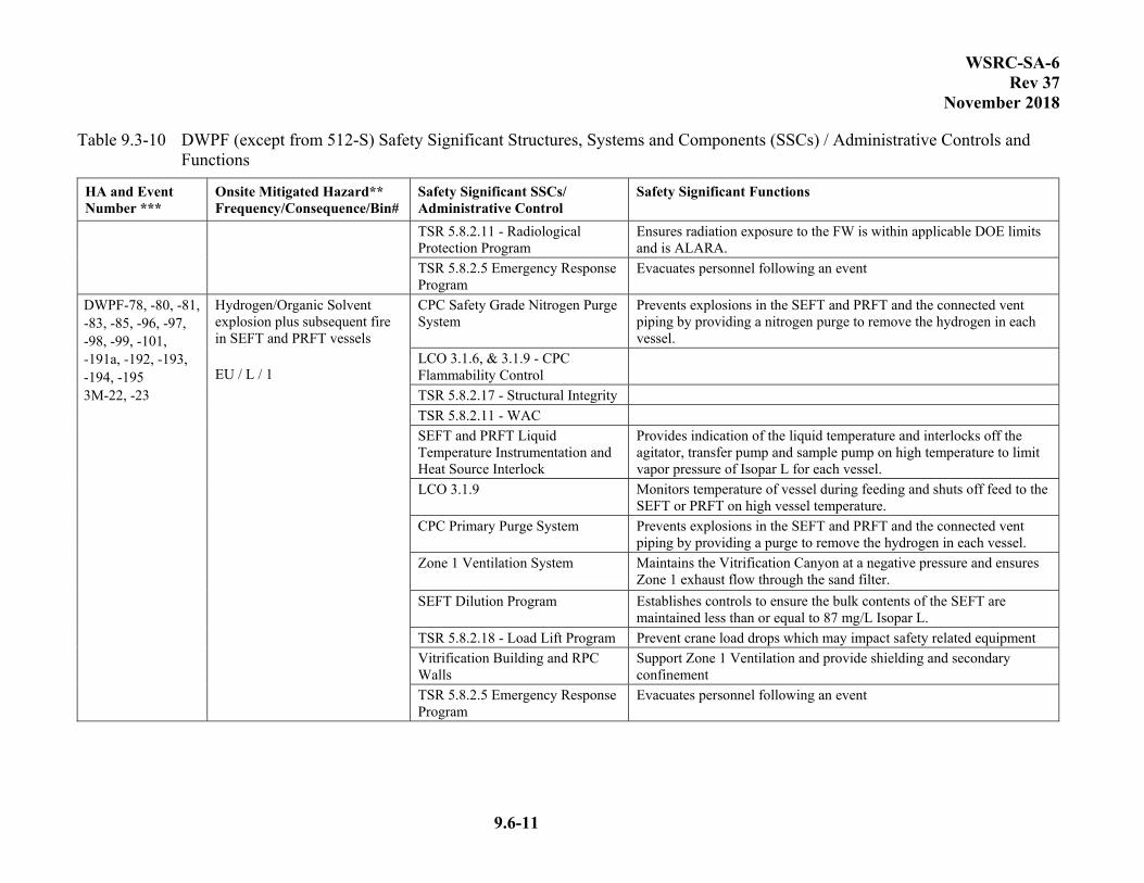
WSRC-SA-6 Rev 37
November 2018
9.6-11
Table 9.3-10 DWPF (except from 512-S) Safety Significant Structures, Systems and Components (SSCs) / Administrative Controls and Functions
HA and Event Number ***
Onsite Mitigated Hazard** Frequency/Consequence/Bin#
Safety Significant SSCs/ Administrative Control
Safety Significant Functions
TSR 5.8.2.11 - Radiological Protection Program
Ensures radiation exposure to the FW is within applicable DOE limits and is ALARA.
TSR 5.8.2.5 Emergency Response Program
Evacuates personnel following an event
DWPF-78, -80, -81, -83, -85, -96, -97, -98, -99, -101, -191a, -192, -193, -194, -195 3M-22, -23
Hydrogen/Organic Solvent explosion plus subsequent fire in SEFT and PRFT vessels EU / L / 1
CPC Safety Grade Nitrogen Purge System
Prevents explosions in the SEFT and PRFT and the connected vent piping by providing a nitrogen purge to remove the hydrogen in each vessel.
LCO 3.1.6, & 3.1.9 - CPC Flammability Control
TSR 5.8.2.17 - Structural Integrity
TSR 5.8.2.11 - WAC
SEFT and PRFT Liquid Temperature Instrumentation and Heat Source Interlock
Provides indication of the liquid temperature and interlocks off the agitator, transfer pump and sample pump on high temperature to limit vapor pressure of Isopar L for each vessel.
LCO 3.1.9 Monitors temperature of vessel during feeding and shuts off feed to the SEFT or PRFT on high vessel temperature.
CPC Primary Purge System
Prevents explosions in the SEFT and PRFT and the connected vent piping by providing a purge to remove the hydrogen in each vessel.
Zone 1 Ventilation System
Maintains the Vitrification Canyon at a negative pressure and ensures Zone 1 exhaust flow through the sand filter.
SEFT Dilution Program Establishes controls to ensure the bulk contents of the SEFT are maintained less than or equal to 87 mg/L Isopar L.
TSR 5.8.2.18 - Load Lift Program Prevent crane load drops which may impact safety related equipment
Vitrification Building and RPC Walls
Support Zone 1 Ventilation and provide shielding and secondary confinement
TSR 5.8.2.5 Emergency Response Program
Evacuates personnel following an event

WSRC-SA-6 Rev 37
November 2018
9.6-12
Table 9.3-10 DWPF (except from 512-S) Safety Significant Structures, Systems and Components (SSCs) / Administrative Controls and Functions
HA and Event Number ***
Onsite Mitigated Hazard** Frequency/Consequence/Bin#
Safety Significant SSCs/ Administrative Control
Safety Significant Functions
DWPF-111, -112, -113, -117, -118, -120, -121, -127, -128, -129, -143, -144, -147, -191a, -191b, -192, -193, -194, -195
Hydrogen/Organic Solvent/ADP explosion plus subsequent fire in SRAT, MWWT, and SMECT vessels U / L / 1
CPC Safety Grade Nitrogen Purge System
Prevents explosions in the SRAT and SMECT and the connected vent piping by providing a nitrogen purge to remove the hydrogen and stripped organic vapors from the SRAT vessel bulk vapor space. Prevents explosions in the SMECT and vessels downstream of the SRAT by carrying the organic vapors through the SRAT condenser train precluding the condensation of the organics.
LCO 3.1.1, 3.1.3, 3.1.4, 3.1.6, 3.1.10,&3.1.11 – CPC Flammability Control
TSR 5.8.2.23 – Chemical Controls
TSR 5.8.2.17 – Structural Integrity
TSR 5.8.2.11 – Waste Acceptance Criteria
SRAT Steam flow meter and interlocks
Maintains steam flow to SRAT to steam strip the organic while feeding to prevent accumulation and interlocks SEFT/PRFT transfer pump on low steam flow. Prevents condensation of the organic in the SRAT condenser train by ensuring the amount of organic in the SRAT is controlled.
Steam supply piping, check valves, jumper downstream of flow element
Ensure steam is being delivered to the SRAT during a transfer from SEFT or PRFT to steam strip the organic. Prevents condensation of the organic in the SRAT condenser train by ensuring the amount of organic in the SRAT is controlled.
SRAT Liquid Temperature Instrumentation and SRAT Feed Interlock
Provides indication of the liquid temperature and interlocks off the SEFT/PRFT transfer pump on low temperature to prevent organic accumulation in the SRAT. Protects against steam coil failure. Prevents condensation of the organic in the SRAT condenser train by ensuring the amount of organic in the SRAT is controlled.
SEFT agitator interlock Shuts off SEFT transfer pump on low agitator power to prevent organic accumulation in the SRAT. Prevents condensation of the organic in the SRAT condenser train by ensuring that the organic is added as a mixture rather than as a slug of organics.
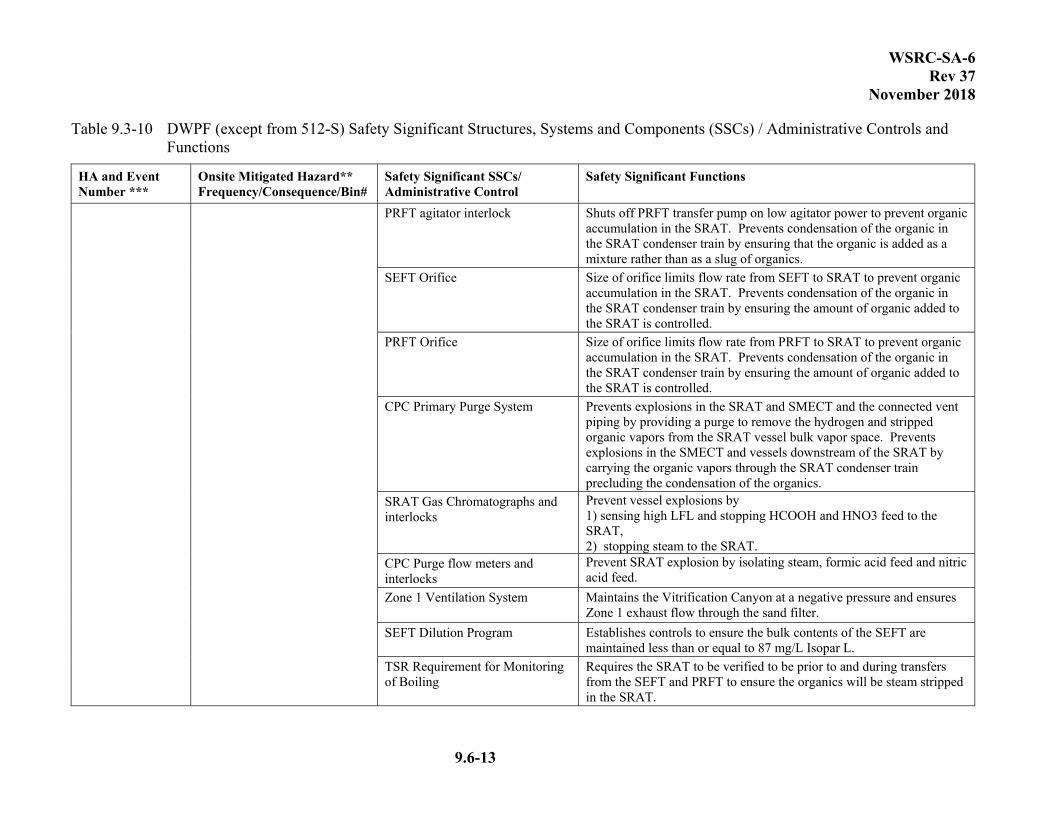
WSRC-SA-6 Rev 37
November 2018
9.6-13
Table 9.3-10 DWPF (except from 512-S) Safety Significant Structures, Systems and Components (SSCs) / Administrative Controls and Functions
HA and Event Number ***
Onsite Mitigated Hazard** Frequency/Consequence/Bin#
Safety Significant SSCs/ Administrative Control
Safety Significant Functions
PRFT agitator interlock Shuts off PRFT transfer pump on low agitator power to prevent organic accumulation in the SRAT. Prevents condensation of the organic in the SRAT condenser train by ensuring that the organic is added as a mixture rather than as a slug of organics.
SEFT Orifice Size of orifice limits flow rate from SEFT to SRAT to prevent organic accumulation in the SRAT. Prevents condensation of the organic in the SRAT condenser train by ensuring the amount of organic added to the SRAT is controlled.
PRFT Orifice Size of orifice limits flow rate from PRFT to SRAT to prevent organic accumulation in the SRAT. Prevents condensation of the organic in the SRAT condenser train by ensuring the amount of organic added to the SRAT is controlled.
CPC Primary Purge System
Prevents explosions in the SRAT and SMECT and the connected vent piping by providing a purge to remove the hydrogen and stripped organic vapors from the SRAT vessel bulk vapor space. Prevents explosions in the SMECT and vessels downstream of the SRAT by carrying the organic vapors through the SRAT condenser train precluding the condensation of the organics.
SRAT Gas Chromatographs and interlocks
Prevent vessel explosions by 1) sensing high LFL and stopping HCOOH and HNO3 feed to the SRAT, 2) stopping steam to the SRAT.
CPC Purge flow meters and interlocks
Prevent SRAT explosion by isolating steam, formic acid feed and nitric acid feed.
Zone 1 Ventilation System
Maintains the Vitrification Canyon at a negative pressure and ensures Zone 1 exhaust flow through the sand filter.
SEFT Dilution Program Establishes controls to ensure the bulk contents of the SEFT are maintained less than or equal to 87 mg/L Isopar L.
TSR Requirement for Monitoring of Boiling
Requires the SRAT to be verified to be prior to and during transfers from the SEFT and PRFT to ensure the organics will be steam stripped in the SRAT.

WSRC-SA-6 Rev 37
November 2018
9.6-14
Table 9.3-10 DWPF (except from 512-S) Safety Significant Structures, Systems and Components (SSCs) / Administrative Controls and Functions
HA and Event Number ***
Onsite Mitigated Hazard** Frequency/Consequence/Bin#
Safety Significant SSCs/ Administrative Control
Safety Significant Functions
TSR 5.8.2.36 Retained Hydrogen Program
Prevents significant accumulation of retained hydrogen from being released in the vessel and exceeding LFL or CLFL by requiring actions to be taken to resume agitation or remove the agitator (or components creating an equal or larger opening size) within a certain period of time.
TSR 5.8.2.5 Emergency Response Program
Evacuates personnel following event
TSR 5.8.2.18 – Load Lift Program Prevent crane load drops which may impact safety related equipment
Vitrification Building and RPC Walls
Support Zone 1 Ventilation and provide shielding and secondary confinement
TSR 5.8.2.11 - Radiological Protection Program
Ensures radiation exposure to the FW is within applicable DOE limits and is ALARA.
App A, A-2.01, DWPF-154
Melter Steam Explosion EU / L / 1
Melter Maintains its integrity to contain its contents.
TSR 5.8.2.11 - Waste Acceptance Criteria*
Ensures salt concentration is sufficiently low to prevent salt buildup in the Melter cold cap.
Zone 1 Ventilation System
Maintains the Vitrification Canyon at a negative pressure and ensures Zone 1 exhaust flow through the sand filter.
Remote Process Cell Walls Provide shielding for the workers within the vitrification building.
DWPF-158, -194
Melt Cell Crane falls during or after seismic event. A / L / 2
Melt Cell Crane*
Prevent the crane from falling on the melter or melter off-gas system.
Zone 1 Ventilation System
Maintains the Vitrification Canyon at a negative pressure and ensures Zone 1 exhaust flow through the sand filter.
Vitrification Building and RPC Walls
Support the Zone 1 Ventilation System airflow configuration and provide confinement and shielding.
TSR 5.8.2.17 - Structural Integrity
TSR 5.8.2.18 – Load Lift Program Prevent crane load drops which may impact safety related equipment
Emergency Response Program Evacuates personnel following event
App A, A-2.02 Deleted

WSRC-SA-6 Rev 37
November 2018
9.6-15
Table 9.3-10 DWPF (except from 512-S) Safety Significant Structures, Systems and Components (SSCs) / Administrative Controls and Functions
HA and Event Number ***
Onsite Mitigated Hazard** Frequency/Consequence/Bin#
Safety Significant SSCs/ Administrative Control
Safety Significant Functions
App A, A-2.03 85 psig steam line failure causes overpressurization in CPC/SPC vessels EU / M / 3
CPC/SPC Vessels (SEFT, PRFT, SRAT, SME, and MFT)
Prevent the release of the contents into the canyon.
Zone 1 Ventilation System Maintains the Vitrification Canyon at a negative pressure and ensures Zone 1 exhaust flow through the sand filter.
App A, A-2.04 Deleted
App A, A-2.07 Cooling water coils- 85 psig causes overpressurization in CPC/SPC vessels EU / L / 1
CPC/SPC Vessels (SEFT, PRFT, SRAT, SME, and MFT)
Prevent the release of the contents into the canyon.
Zone 1 Ventilation System
Maintains the Vitrification Canyon at a negative pressure, ensures Zone 1 exhaust flow through the sand filter.
DWPF-152, -153, -191b, -192 -193, -194, -195
Melter Off-gas Explosion EU / L / 1
TSR 5.8.2.37 Melter Flammability Control Program
Prevents explosion by limiting the concentration of flammable gases in the off-gas based on controlling multiple parameters (melter feed rate, dilution air flow, feed composition, and OGCT temperature).
Vitrification Building and Cell Covers
Provides secondary confinement.
Emergency Response Program Evacuates personnel following event. Zone 1 Ventilation System
Maintains the Vitrification Canyon at a negative pressure and ensures Zone 1 exhaust flow through the sand filter.
TSR 5.8.2.30 Seismic Event Response
Prevents flammability in the melter off-gas by immediately stopping melter feed following a seismic event.
RPC Walls Provide shielding for the workers within the vitrification building.
App A, B-1.01 Deleted
App A, B-1.02 Deleted

WSRC-SA-6 Rev 37
November 2018
9.6-16
Table 9.3-10 DWPF (except from 512-S) Safety Significant Structures, Systems and Components (SSCs) / Administrative Controls and Functions
HA and Event Number ***
Onsite Mitigated Hazard** Frequency/Consequence/Bin#
Safety Significant SSCs/ Administrative Control
Safety Significant Functions
App A, B-1.04 (a, b, c, d, e) NOTE: RCT and DWTT not included in PHA event DWPF-85, -101, -118, -162, -168, -171
Fire in a CPC/SPC vessel or cell EU / L / 1
CPC Safety Grade Nitrogen Purge System
Prevents explosions in the SEFT, PRFT, SRAT, SME, SMECT, MFT, RCT, DWTT and the connected vent piping by providing a nitrogen purge to each vessel.
CPC Primary Purge System Prevents explosions in the SEFT, PRFT, SRAT, SME, SMECT, MFT, RCT, DWTT and the connected vent piping by providing a purge to each vessel.
Zone 1 Ventilation System
Maintains the Vitrification Canyon at a negative pressure, ensures Zone 1 exhaust flow through the sand filter.
Temperature Monitor and Interlock
Provides indication of the liquid temperature and interlocks off the agitator, transfer pump, and sample pump upon high temperature to limit vapor pressure of Isopar-L. Interlocks SEFT/PRFT transfer pump on low temperature.
LCO 3.1.9 Response Action Shuts off feed to PRFT upon high temperature to limit vapor pressure of Isopar-L.
SEFT Dilution Program Establishes controls to ensure the bulk contents of the SEFT are maintained less than or equal to 87 mg/L Isopar L.
Steam Supply Piping, Check Valves, Jumper Downstream of Flow Element
Ensures steam is being delivered to the SRAT
Steam Flow Meter and Interlock Steam strips organic while feeding to prevent accumulation and interlocks SEFT/PRFT transfer pump on no/low steam flow.
SEFT/PRFT Agitator Interlock Interlocks SEFT/PRFT transfer pump on no/ow agitator power.
SEFT/PRFT Orifice Limits flow rate from SEFT/PRFT to SRAT.
TSR Requirement for Monitoring of Agitation
Requires the SEFT/PRFT to have agitation 2 hours prior to and during transfers to the SRAT to ensure well mixed waste.
TSR Requirement for Monitoring of Boiling
Requires the SRAT to be verified to be boiling prior to and during transfers from the SEFT and PRFT to ensure the organics will be steam stripped in the SRAT.
SPC/CPC Tanks Seismically qualified to contain contents
Vitrification Building and Cell Covers
Supports Zone 1 Ventilation and seismically qualified to not fail

WSRC-SA-6 Rev 37
November 2018
9.6-17
Table 9.3-10 DWPF (except from 512-S) Safety Significant Structures, Systems and Components (SSCs) / Administrative Controls and Functions
HA and Event Number ***
Onsite Mitigated Hazard** Frequency/Consequence/Bin#
Safety Significant SSCs/ Administrative Control
Safety Significant Functions
App A, B-1.06 Deleted
App A, B-3.07 DWPF-156
Melter Electrode Fire Leads to Melter Overpressurization Other events with causes for a Melter overpressurization are included here as well. A / L / 1
Melter Maintains its integrity to contain its contents.
Zone 1 Ventilation System Maintains the Vitrification Canyon at a negative pressure and ensures Zone 1 exhaust flow through the sand filter.
Vitrification Building and RPC Walls
Support Zone 1 Ventilation and provide shielding and secondary confinement
TSR 5.8.2.5 Emergency Response Program
Evacuates personnel following an event
App A, C-1.01 Failure or Misoperation of 117-Ton Main Process Cell Crane Results in Confinement Breach U / L / 2
TSR 5.8.2.18- Load Lift Program Prevent loads from being dropped on safety related SSCs.
Zone 1 Ventilation System
Maintains the Vitrification Canyon at a negative pressure and ensures Zone 1 exhaust flow through the sand filter.
Main Process Cell (MPC) Crane Structure
Prevent the crane from falling and causing the failure of tanks holding radioactive or hazardous materials.
Remote Process Cell Walls Support Zone 1 Ventilation and provide shielding.
App A, C-1.15 Cell Manipulator Monorail Hoist Failure/Misoperation (Level 1 East and North Corridors) fails shielded viewing windows EU / M / 3
Administrative Control - Radiological Protection Program
Alerts the worker of potential hazards.
TSR 5.8.2.1 - Radiological Protection Program
Zone 1 Ventilation System
Maintains the Vitrification Canyon at a negative pressure and ensures Zone 1 exhaust flow through the sand filter.
App A, C-2.03 Mechanical confinement breach of Canister in Load Out Area U / L / 2
TSR 5.8.2.1- Radiological Protection Program
Requires monitoring during SCT loading/unloading to ensure canister is shielded.
DWPF-124, -148, -186, -187
Radiation from Process Vessels from failed shielded viewing window. Other similar scenarios involving direct radiation and shine in the CPC/SPC are also included.
221-S Shielded Viewing Windows Shields Viewers from radiation
TSR 5.8.2.1 - Radiological Protection Program
Ensures radiological exposure to FW is within applicable DOE limits and is ALARA.
TSR 5.8.2.18 - Load Lift Program Prevent crane load drops which may impact safety related equipment
Vitrification Building and RPC Walls
Provides shielding

WSRC-SA-6 Rev 37
November 2018
9.6-18
Table 9.3-10 DWPF (except from 512-S) Safety Significant Structures, Systems and Components (SSCs) / Administrative Controls and Functions
HA and Event Number ***
Onsite Mitigated Hazard** Frequency/Consequence/Bin#
Safety Significant SSCs/ Administrative Control
Safety Significant Functions
A / L / 2 TSR 5.8.2.5 Emergency Response Program
Evacuates personnel following an event
App A, D-1.02 50% Caustic (NAK) and 50% nitric acid (NIK) distribution line failures in Lvl 3 U / L / 2
Nitric Acid Feed Tank and Piping Provides a barrier to prevent the release of nitric acid.
Nitric Acid Feed Tank Dikes Provide containment of any spilled inventory.
Administrative Control - Structural Integrity Program
Ensures integrity of the tanks.
50% Caustic is a common industrial hazard.
App A, D-1.05 DWPF-91, -105, -106, -122, -123 3M-24, 3M-28
Corrosion caused by nitric acid, formic acid, and/or acidic SE or erosion breaches the CPC/SPC vessels. This spill and leak scenario also includes causes such as vessel overflows due to transfer errors or equipment
CPC/SPC Vessels (SEFT, PRFT, SRAT, SME, SMECT, MFT, RCT, and DWTT) TSR 5.8.2. 17 - Structural Integrity
Prevent the release of the contents into the canyon and contain the contents to allow the purge system to function.
Zone 1 Ventilation System
Maintains the Vitrification Canyon at a negative pressure, ensures Zone 1 exhaust flow through the sand filter.
Vitrification Building and RPC Walls
Support the Zone 1 Ventilation System airflow configuration and provide confinement and shielding.
TSR 5.8.2.1 - Radiological Protection Program
Ensures radiological exposure to FW is within applicable DOE limits and is ALARA.
TSR 5.8.2.18 – Load Lift Program Prevent load drops in the LPPP resulting in a spill, explosion or vessel failure.
DWPF-73, -74, -75, -76, -77 3M-21
Spill or leak from jumpers in CPC/SPC due to corrosion, equipment malfunction/ plugging or incorrect jumper connections. A / L/ 1
Zone 1 Ventilation System
Maintains the Vitrification Canyon at a negative pressure, ensures Zone 1 exhaust flow through the sand filter.
TSR 5.8.2.1 - Radiological Protection Program
Ensures radiological exposure to FW is within applicable DOE limits and is ALARA.
Vitrification Building and RPC Walls
Support the Zone 1 Ventilation System airflow configuration and provide confinement and shielding.
TSR 5.8.2.18 – Load Lift Program Prevent load drops in the LPPP resulting in a spill, explosion or vessel failure.

WSRC-SA-6 Rev 37
November 2018
9.6-19
Table 9.3-10 DWPF (except from 512-S) Safety Significant Structures, Systems and Components (SSCs) / Administrative Controls and Functions
HA and Event Number ***
Onsite Mitigated Hazard** Frequency/Consequence/Bin#
Safety Significant SSCs/ Administrative Control
Safety Significant Functions
App A, D-2.01 Chemical confinement breach from incorrect jumper connection (chemical interaction between process cells and DWTT or RCT) EU / L / 1
Administrative Control - Sampling Program TSR 5.8.2.23 - Chemical Controls
Ensures correct material is being transferred into a tank whose contents are known.
Zone 1 Ventilation System
Maintains the Vitrification Canyon at a negative pressure, ensures Zone 1 exhaust flow through the sand filter.
App A, F-1.02 Toxic-Pathogenic danger due to Formic Acid Vapor (Third Level) EU / M / 3
Formic Acid Feed Tank and Piping TSR 5.8.2. 17 - Structural Integrity
Provides a barrier to prevent the release of formic acid.
Formic Acid Feed Tank Dikes Provide containment of any spilled inventory.
Note: This is not a PHA event
Formic/Nitric Acid interaction in the tunnel level drain catch tank area U / L / 2
Organic Acid Drain Catch Tank and Piping TSR 5.8.2.17 - Structural Integrity
Prevent Formic Acid from mixing with Nitric Acid
Organic Acid Drain Catch Tank Dike
Prevent formic acid from mixing with nitric acid
Acid Drain Catch Tank And Tank Platform
Prevent Acid Drain Catch Tank and Platform from Interacting with Organic Acid Drain Catch Tank during and after seismic event.
Note: This is not a PHA Event
221-S Third Level Chemical Reaction due to leaks spills and overflows (sodium nitrite and either nitric acid or formic acid). U / L / 2
Formic Acid Feed Tank and Piping
Provide a barrier to prevent the release of its contents.
Formic Acid Feed Tank dikes Provide containment of any spilled inventory
Nitric Acid Feed Tank and Piping Provide a barrier to prevent the release of its contents.
Nitric Acid Feed Tank dikes Provide containment of any spilled inventory
Note: This is not a PHA Event
221-S Tunnel Level Chemical Reaction due to leaks spills and overflows (sodium nitrite and either nitric acid or formic acid) U / L / 2
Acid Drain Catch Tank and Piping Provide a barrier to prevent the release of its contents.
Acid Drain Catch Tank dikes Provide containment of any spilled inventory.
Organic Acid Drain Catch Tank and Piping
Provide a barrier to prevent the release of its contents.
Organic Acid Drain Catch Tank dikes
Provide containment of any spilled inventory.
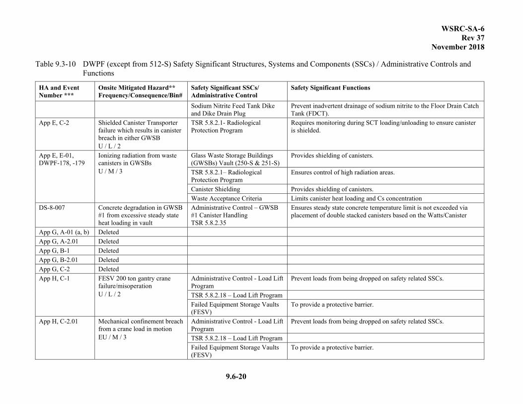
WSRC-SA-6 Rev 37
November 2018
9.6-20
Table 9.3-10 DWPF (except from 512-S) Safety Significant Structures, Systems and Components (SSCs) / Administrative Controls and Functions
HA and Event Number ***
Onsite Mitigated Hazard** Frequency/Consequence/Bin#
Safety Significant SSCs/ Administrative Control
Safety Significant Functions
Sodium Nitrite Feed Tank Dike and Dike Drain Plug
Prevent inadvertent drainage of sodium nitrite to the Floor Drain Catch Tank (FDCT).
App E, C-2 Shielded Canister Transporter failure which results in canister breach in either GWSB U / L / 2
TSR 5.8.2.1- Radiological Protection Program
Requires monitoring during SCT loading/unloading to ensure canister is shielded.
App E, E-01, DWPF-178, -179
Ionizing radiation from waste canisters in GWSBs U / M / 3
Glass Waste Storage Buildings (GWSBs) Vault (250-S & 251-S)
Provides shielding of canisters.
TSR 5.8.2.1– Radiological Protection Program
Ensures control of high radiation areas.
Canister Shielding Provides shielding of canisters.
Waste Acceptance Criteria Limits canister heat loading and Cs concentration
DS-8-007 Concrete degradation in GWSB #1 from excessive steady state heat loading in vault
Administrative Control – GWSB #1 Canister Handling TSR 5.8.2.35
Ensures steady state concrete temperature limit is not exceeded via placement of double stacked canisters based on the Watts/Canister
App G, A-01 (a, b) Deleted
App G, A-2.01 Deleted
App G, B-1 Deleted
App G, B-2.01 Deleted
App G, C-2 Deleted
App H, C-1 FESV 200 ton gantry crane failure/misoperation U / L / 2
Administrative Control - Load Lift Program
Prevent loads from being dropped on safety related SSCs.
TSR 5.8.2.18 – Load Lift Program
Failed Equipment Storage Vaults (FESV)
To provide a protective barrier.
App H, C-2.01 Mechanical confinement breach from a crane load in motion EU / M / 3
Administrative Control - Load Lift Program
Prevent loads from being dropped on safety related SSCs.
TSR 5.8.2.18 – Load Lift Program
Failed Equipment Storage Vaults (FESV)
To provide a protective barrier.
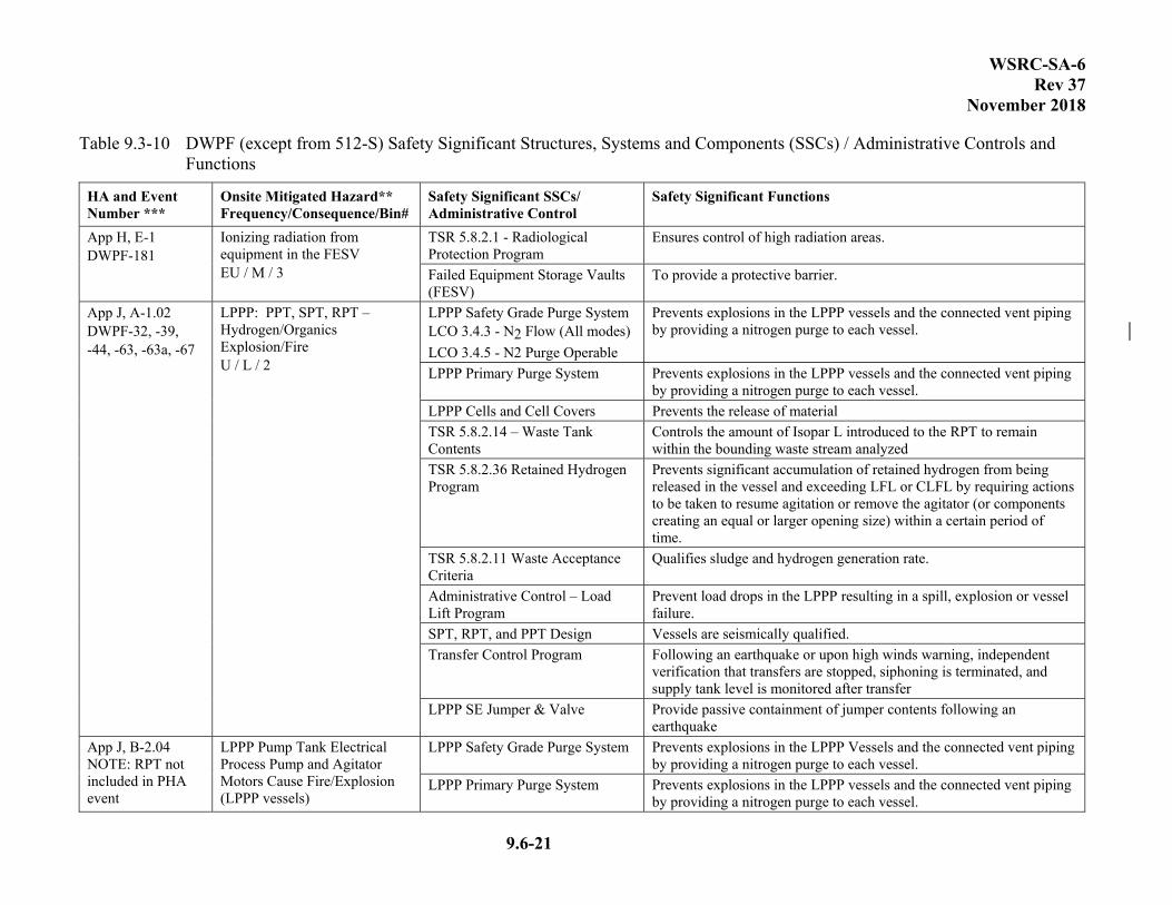
WSRC-SA-6 Rev 37
November 2018
9.6-21
Table 9.3-10 DWPF (except from 512-S) Safety Significant Structures, Systems and Components (SSCs) / Administrative Controls and Functions
HA and Event Number ***
Onsite Mitigated Hazard** Frequency/Consequence/Bin#
Safety Significant SSCs/ Administrative Control
Safety Significant Functions
App H, E-1 DWPF-181
Ionizing radiation from equipment in the FESV EU / M / 3
TSR 5.8.2.1 - Radiological Protection Program
Ensures control of high radiation areas.
Failed Equipment Storage Vaults (FESV)
To provide a protective barrier.
App J, A-1.02 DWPF-32, -39, -44, -63, -63a, -67
LPPP: PPT, SPT, RPT – Hydrogen/Organics Explosion/Fire U / L / 2
LPPP Safety Grade Purge System LCO 3.4.3 - N2 Flow (All modes)
LCO 3.4.5 - N2 Purge Operable
Prevents explosions in the LPPP vessels and the connected vent piping by providing a nitrogen purge to each vessel.
LPPP Primary Purge System Prevents explosions in the LPPP vessels and the connected vent piping by providing a nitrogen purge to each vessel.
LPPP Cells and Cell Covers Prevents the release of material
TSR 5.8.2.14 – Waste Tank Contents
Controls the amount of Isopar L introduced to the RPT to remain within the bounding waste stream analyzed
TSR 5.8.2.36 Retained Hydrogen Program
Prevents significant accumulation of retained hydrogen from being released in the vessel and exceeding LFL or CLFL by requiring actions to be taken to resume agitation or remove the agitator (or components creating an equal or larger opening size) within a certain period of time.
TSR 5.8.2.11 Waste Acceptance Criteria
Qualifies sludge and hydrogen generation rate.
Administrative Control – Load Lift Program
Prevent load drops in the LPPP resulting in a spill, explosion or vessel failure.
SPT, RPT, and PPT Design Vessels are seismically qualified.
Transfer Control Program Following an earthquake or upon high winds warning, independent verification that transfers are stopped, siphoning is terminated, and supply tank level is monitored after transfer
LPPP SE Jumper & Valve Provide passive containment of jumper contents following an earthquake
App J, B-2.04 NOTE: RPT not included in PHA event
LPPP Pump Tank Electrical Process Pump and Agitator Motors Cause Fire/Explosion (LPPP vessels)
LPPP Safety Grade Purge System Prevents explosions in the LPPP Vessels and the connected vent piping by providing a nitrogen purge to each vessel.
LPPP Primary Purge System Prevents explosions in the LPPP vessels and the connected vent piping by providing a nitrogen purge to each vessel.

WSRC-SA-6 Rev 37
November 2018
9.6-22
Table 9.3-10 DWPF (except from 512-S) Safety Significant Structures, Systems and Components (SSCs) / Administrative Controls and Functions
HA and Event Number ***
Onsite Mitigated Hazard** Frequency/Consequence/Bin#
Safety Significant SSCs/ Administrative Control
Safety Significant Functions
U / L / 2 LPPP Vessels Prevent the release of the contents in the cell and contain the contents to allow the purge system to function.
TSR 5.8.2.14 – Waste Tank Contents
Controls the amount of Isopar L introduced to the RPT to remain within the bounding waste stream analyzed
App J, B-2.05 NOTE: RPT not included in PHA event
Lightning Causes Fire and Subsequent Explosion (LPPP vessels) EU / M / 3
LPPP Safety Grade Purge System Prevents explosions in the LPPP vessels and the connected vent piping by providing a nitrogen purge to each vessel.
LPPP Primary Purge System Prevents explosions in the LPPP vessels and the connected vent piping by providing a nitrogen purge to each vessel.
LPPP Vessels Prevent the release of the contents in the cell and contain the contents to allow the purge system to function.
TSR 5.8.2.14 – Waste Tank Contents
Controls the amount of Isopar L introduced to the RPT to remain within the bounding waste stream analyzed
App J, B-2.06 NOTE: RPT not included in PHA event
Electrical Fault above LPPP Pump Tanks Causes Fire and Subsequent Explosion (Welding receptacles, transformer leak detection equipment) (LPPP vessels) EU / M / 3
LPPP Safety Grade Purge System Prevents explosions in the LPPP vessels and the connected vent piping by providing a nitrogen purge to each vessel.
LPPP Primary Purge System Prevents explosions in the LPPP vessels and the connected vent piping by providing a nitrogen purge to each vessel.
LPPP Vessels Prevent the release of the contents in the cell and contain the contents to allow the purge system to function.
TSR 5.8.2.14 – Waste Tank Contents
Controls the volume of Isopar L introduced to the RPT to remain within the bounding waste stream analyzed
App J, C-1.03 Deleted
App J, C-3.02 Deleted
App J, C-3.07 Deleted
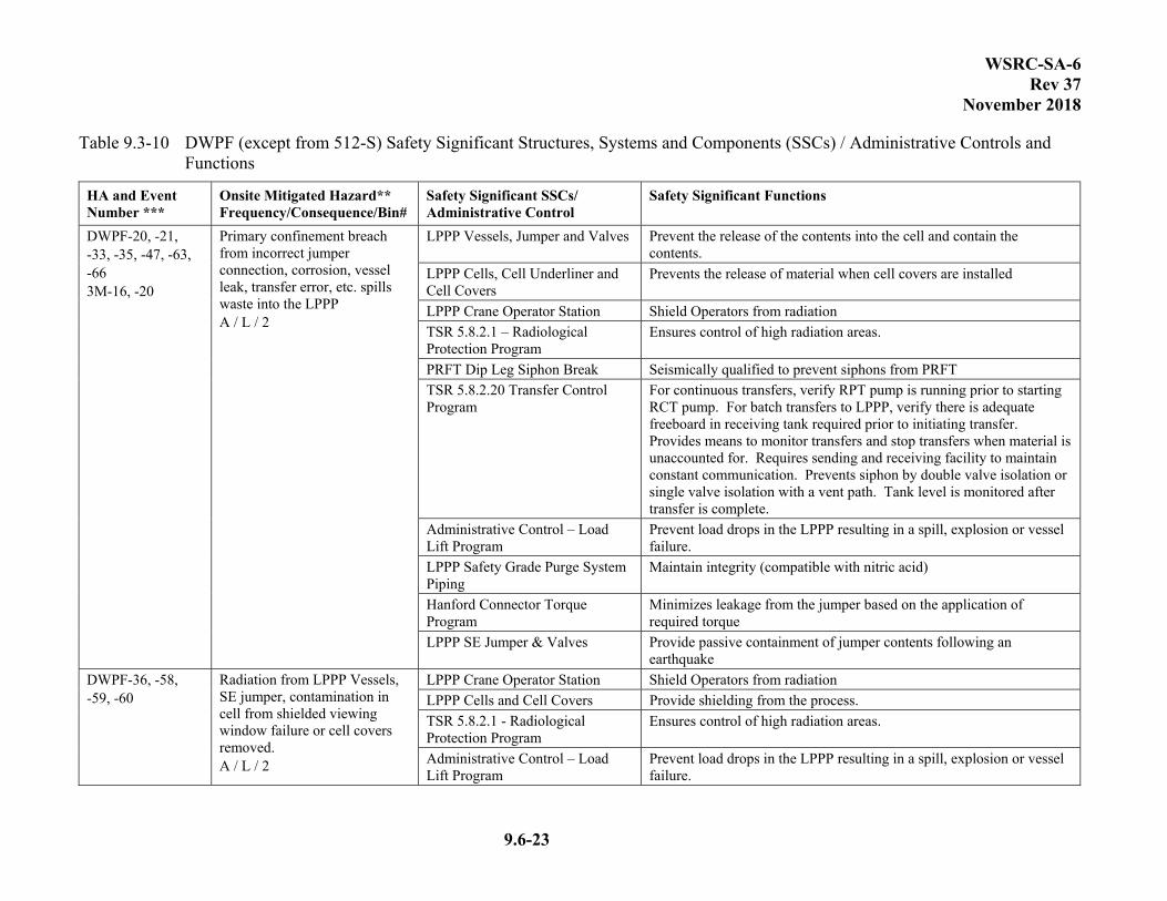
WSRC-SA-6 Rev 37
November 2018
9.6-23
Table 9.3-10 DWPF (except from 512-S) Safety Significant Structures, Systems and Components (SSCs) / Administrative Controls and Functions
HA and Event Number ***
Onsite Mitigated Hazard** Frequency/Consequence/Bin#
Safety Significant SSCs/ Administrative Control
Safety Significant Functions
DWPF-20, -21, -33, -35, -47, -63, -66 3M-16, -20
Primary confinement breach from incorrect jumper connection, corrosion, vessel leak, transfer error, etc. spills waste into the LPPP A / L / 2
LPPP Vessels, Jumper and Valves Prevent the release of the contents into the cell and contain the contents.
LPPP Cells, Cell Underliner and Cell Covers
Prevents the release of material when cell covers are installed
LPPP Crane Operator Station Shield Operators from radiation
TSR 5.8.2.1 – Radiological Protection Program
Ensures control of high radiation areas.
PRFT Dip Leg Siphon Break Seismically qualified to prevent siphons from PRFT
TSR 5.8.2.20 Transfer Control Program
For continuous transfers, verify RPT pump is running prior to starting RCT pump. For batch transfers to LPPP, verify there is adequate freeboard in receiving tank required prior to initiating transfer. Provides means to monitor transfers and stop transfers when material is unaccounted for. Requires sending and receiving facility to maintain constant communication. Prevents siphon by double valve isolation or single valve isolation with a vent path. Tank level is monitored after transfer is complete.
Administrative Control – Load Lift Program
Prevent load drops in the LPPP resulting in a spill, explosion or vessel failure.
LPPP Safety Grade Purge System Piping
Maintain integrity (compatible with nitric acid)
Hanford Connector Torque Program
Minimizes leakage from the jumper based on the application of required torque
LPPP SE Jumper & Valves Provide passive containment of jumper contents following an earthquake
DWPF-36, -58, -59, -60
Radiation from LPPP Vessels, SE jumper, contamination in cell from shielded viewing window failure or cell covers removed. A / L / 2
LPPP Crane Operator Station Shield Operators from radiation
LPPP Cells and Cell Covers Provide shielding from the process.
TSR 5.8.2.1 - Radiological Protection Program
Ensures control of high radiation areas.
Administrative Control – Load Lift Program
Prevent load drops in the LPPP resulting in a spill, explosion or vessel failure.

WSRC-SA-6 Rev 37
November 2018
9.6-24
Table 9.3-10 DWPF (except from 512-S) Safety Significant Structures, Systems and Components (SSCs) / Administrative Controls and Functions
HA and Event Number ***
Onsite Mitigated Hazard** Frequency/Consequence/Bin#
Safety Significant SSCs/ Administrative Control
Safety Significant Functions
DWPF-63a Vehicle crash into N2 supply tanks to LPPP
Administrative Control – Traffic Control Program
Prevents loss of nitrogen supply to LPPP, which could result in vessel explosion.
DWPF-157, -158
Spill of Molten Glass in the Melt Cell
Zone 1 Ventilation System
Maintains the Vitrification Canyon at a negative pressure, ensures Zone 1 exhaust flow through the sand filter.
Administrative Control – Emergency Response Program
Defines specific measures, policies, and actions to prevent or minimize injuries, damage to property, and impact on the environment.
Melter Vessel Melter must maintain its integrity to contain its contents.
Vitrification Building and RPC Walls
Support the Zone 1 Ventilation System airflow configuration and provide shielding.
DWPF-1, -27c, -27e
Fire in or around transfer line
Core Pipe Maintain integrity to provide containment
Secondary Containment Maintain structural integrity against significant failure to provide gross containment (excludes SE line)
Fire Protection Program Limits transient combustible loading
Emergency Response Program Evacuates personnel following event
DWPF-1a, -2, -3 3M-1
Transfer line core pipe explosion
Core Pipe Maintain integrity to provide containment
Secondary Containment Maintain structural integrity against significant failure to provide gross containment (excludes SE line)
Fire Protection Program Limits transient combustible loading
Emergency Response Program Evacuates personnel following event
DWPF-4, -5 Transfer line jacket explosion Core Pipe Maintain integrity to provide containment
Secondary Containment Maintain structural integrity against significant failure to provide gross containment (excludes SE line)
Emergency Response Program Evacuates personnel following event
DWPF-9 Transfer line core pipe or jumper explosion damages tank resulting in release
LPPP Vessels Prevents release of SPT, RPT, and PPT contents
LPPP Cell and Cell Covers Mitigates release of material
Crane Operator Station Shield operators when cell covers not installed
DWPF-10
Transfer line core pipe explosion damages jumper resulting in a spill to the LPPP
Core Pipe Maintain integrity to provide containment
Hanford Connector Torque Program
Ensure Hanford Connectors are secured with torque
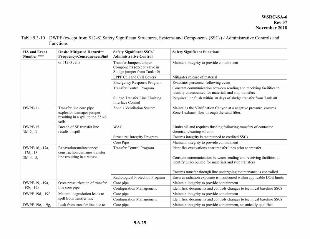
WSRC-SA-6 Rev 37
November 2018
9.6-25
Table 9.3-10 DWPF (except from 512-S) Safety Significant Structures, Systems and Components (SSCs) / Administrative Controls and Functions
HA and Event Number ***
Onsite Mitigated Hazard** Frequency/Consequence/Bin#
Safety Significant SSCs/ Administrative Control
Safety Significant Functions
or 512-S cells
Transfer Jumper/Jumper Components (except valve in Sludge jumper from Tank 40)
Maintain integrity to provide containment
LPPP Cell and Cell Covers Mitigates release of material
Emergency Response Program Evacuates personnel following event
Transfer Control Program Constant communication between sending and receiving facilities to identify unaccounted for materials and stop transfers
Sludge Transfer Line Flushing Interface Control
Requires line flush within 30 days of sludge transfer from Tank 40
DWPF-11 Transfer line core pipe explosion damages jumper resulting in a spill to the 221-S cells
Zone 1 Ventilation System Maintains the Vitrification Canyon at a negative pressure, ensures Zone 1 exhaust flow through the sand filter.
DWPF-15 3M-2, -3
Breach of SE transfer line results in spill
WAC Limits pH and requires flushing following transfers of contactor chemical cleaning solution
Structural Integrity Program Ensures integrity is maintained to credited SSCs
Core Pipe Maintain integrity to provide containment
DWPF-16, -17a, -17d, -18 3M-4, -5,
Excavation/maintenance/ construction damages transfer line resulting in a release
Transfer Control Program Identifies excavations near transfer lines prior to transfer Constant communication between sending and receiving facilities to identify unaccounted for materials and stop transfers Ensures transfer through line undergoing maintenance is controlled
Radiological Protection Program Ensures radiation exposure is maintained within applicable DOE limits
DWPF-19, -19a, -19b, -19c
Over-pressurization of transfer line core pipe
Core pipe Maintain integrity to provide containment
Configuration Management Identifies, documents and controls changes to technical baseline SSCs
DWPF-19d, -19f Material degradation leads to spill from transfer line
Core pipe Maintain integrity to provide containment
Configuration Management Identifies, documents and controls changes to technical baseline SSCs
DWPF-19e, -19g, Leak from transfer line due to Core pipe Maintain integrity to provide containment, seismically qualified.

WSRC-SA-6 Rev 37
November 2018
9.6-26
Table 9.3-10 DWPF (except from 512-S) Safety Significant Structures, Systems and Components (SSCs) / Administrative Controls and Functions
HA and Event Number ***
Onsite Mitigated Hazard** Frequency/Consequence/Bin#
Safety Significant SSCs/ Administrative Control
Safety Significant Functions
-26d, -26e, -26f, -27, -27a, -27b, -27d
external impacts (e.g. cranes, vehicles, NPH)
Load Lift Program Defines controls to minimize potential of damaging safety equipment due to crane load drop
Traffic Control Program Defines controls to minimize potential of damaging safety equipment due to vehicle accidents
Emergency Response Program Evacuates personnel and minimizes potential release following event
Secondary Containment Maintains structural integrity against significant failure to provide gross containment (excludes SE line).
Fire Protection Program Limits transient combustible loading
Transfer Control Program Terminates transfer from Tank 40 and 49 in above ground piping or excavations in event of high winds
DWPF-24, -25, -26, -26a, -26b
Exposure from transfer line Radiation Protection Program Ensures radiation exposure is maintained within applicable DOE limits
Transfer Control Program Identifies excavation near transfer lines prior to transfer
LDB-2, -3, -4
Fire/Explosion in Leak Detection Box
Core Pipe Maintains integrity to provide containment
Fire Protection Program Limits transient combustible loading
Radiological Protection Program Ensures radiation exposure is maintained within applicable DOE limits
Secondary Containment Maintains structural integrity against significant failure to provide gross containment
Emergency Response Program Evacuates personnel and minimizes potential release following event
LDB-5, -6, -7, -9 Release from Leak Detection Box
Core Pipe Maintains integrity to provide containment
Secondary Containment Maintains structural integrity against significant failure to provide gross containment
Radiological Protection Program Ensures radiation exposure is maintained within applicable DOE limits
Transfer Control Program Provide means to monitor and stop transfer when material is unaccounted for
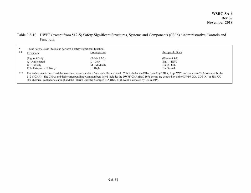
WSRC-SA-6 Rev 37
November 2018
9.6-27
Table 9.3-10 DWPF (except from 512-S) Safety Significant Structures, Systems and Components (SSCs) / Administrative Controls and Functions
* These Safety Class SSCs also perform a safety significant function
** Frequency Consequence Acceptable Bin #
(Figure 9.3-1) (Table 9.3-2) (Figure 9.3-1) A - Anticipated L - Low Bin 1 - EU/L U - Unlikely M - Moderate Bin 2 - U/L EU - Extremely Unlikely H High Bin 3 - A/L
*** For each scenario described the associated event numbers from each HA are listed. This includes the PHA (noted by “PHA, App. XX”) and the main CHAs (except for the 512-S CHA). The CHAs and their corresponding event numbers listed include: the DWPF CHA (Ref. 169) events are denoted by either DWPF-XX, LDB-X, or 3M-XX (for chemical contactor cleaning) and the Interim Canister Storage CHA (Ref. 210) event is denoted by DS-X-00Y.

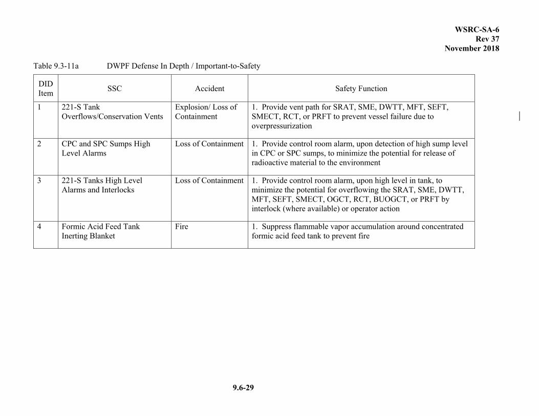
WSRC-SA-6 Rev 37
November 2018
9.6-29
Table 9.3-11a DWPF Defense In Depth / Important-to-Safety
DID Item
SSC Accident Safety Function
1 221-S Tank Overflows/Conservation Vents
Explosion/ Loss of Containment
1. Provide vent path for SRAT, SME, DWTT, MFT, SEFT, SMECT, RCT, or PRFT to prevent vessel failure due to overpressurization
2 CPC and SPC Sumps High Level Alarms
Loss of Containment 1. Provide control room alarm, upon detection of high sump level in CPC or SPC sumps, to minimize the potential for release of radioactive material to the environment
3 221-S Tanks High Level Alarms and Interlocks
Loss of Containment 1. Provide control room alarm, upon high level in tank, to minimize the potential for overflowing the SRAT, SME, DWTT, MFT, SEFT, SMECT, OGCT, RCT, BUOGCT, or PRFT by interlock (where available) or operator action
4 Formic Acid Feed Tank Inerting Blanket
Fire 1. Suppress flammable vapor accumulation around concentrated formic acid feed tank to prevent fire
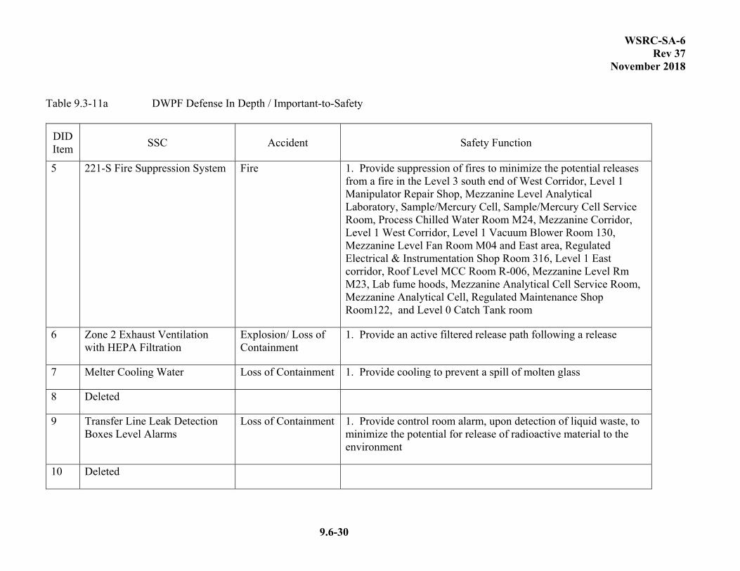
WSRC-SA-6 Rev 37
November 2018
9.6-30
Table 9.3-11a DWPF Defense In Depth / Important-to-Safety
DID Item
SSC Accident Safety Function
5 221-S Fire Suppression System Fire 1. Provide suppression of fires to minimize the potential releases from a fire in the Level 3 south end of West Corridor, Level 1 Manipulator Repair Shop, Mezzanine Level Analytical Laboratory, Sample/Mercury Cell, Sample/Mercury Cell Service Room, Process Chilled Water Room M24, Mezzanine Corridor, Level 1 West Corridor, Level 1 Vacuum Blower Room 130, Mezzanine Level Fan Room M04 and East area, Regulated Electrical & Instrumentation Shop Room 316, Level 1 East corridor, Roof Level MCC Room R-006, Mezzanine Level Rm M23, Lab fume hoods, Mezzanine Analytical Cell Service Room, Mezzanine Analytical Cell, Regulated Maintenance Shop Room122, and Level 0 Catch Tank room
6 Zone 2 Exhaust Ventilation with HEPA Filtration
Explosion/ Loss of Containment
1. Provide an active filtered release path following a release
7 Melter Cooling Water Loss of Containment 1. Provide cooling to prevent a spill of molten glass
8 Deleted
9 Transfer Line Leak Detection Boxes Level Alarms
Loss of Containment 1. Provide control room alarm, upon detection of liquid waste, to minimize the potential for release of radioactive material to the environment
10 Deleted
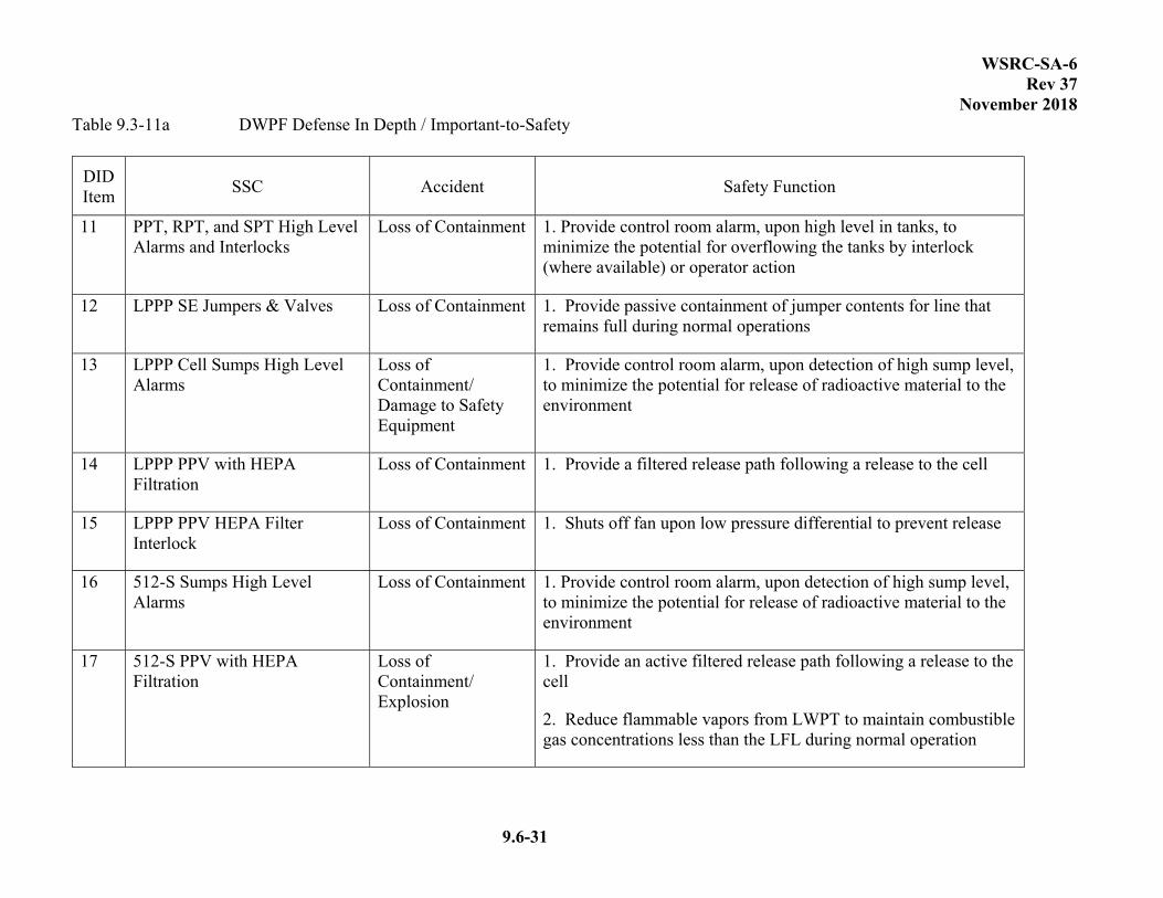
WSRC-SA-6 Rev 37
November 2018
9.6-31
Table 9.3-11a DWPF Defense In Depth / Important-to-Safety
DID Item
SSC Accident Safety Function
11 PPT, RPT, and SPT High Level Alarms and Interlocks
Loss of Containment 1. Provide control room alarm, upon high level in tanks, to minimize the potential for overflowing the tanks by interlock (where available) or operator action
12 LPPP SE Jumpers & Valves Loss of Containment 1. Provide passive containment of jumper contents for line that remains full during normal operations
13 LPPP Cell Sumps High Level Alarms
Loss of Containment/ Damage to Safety Equipment
1. Provide control room alarm, upon detection of high sump level, to minimize the potential for release of radioactive material to the environment
14 LPPP PPV with HEPA Filtration
Loss of Containment 1. Provide a filtered release path following a release to the cell
15 LPPP PPV HEPA Filter Interlock
Loss of Containment 1. Shuts off fan upon low pressure differential to prevent release
16 512-S Sumps High Level Alarms
Loss of Containment 1. Provide control room alarm, upon detection of high sump level, to minimize the potential for release of radioactive material to the environment
17 512-S PPV with HEPA Filtration
Loss of Containment/ Explosion
1. Provide an active filtered release path following a release to the cell
2. Reduce flammable vapors from LWPT to maintain combustible gas concentrations less than the LFL during normal operation
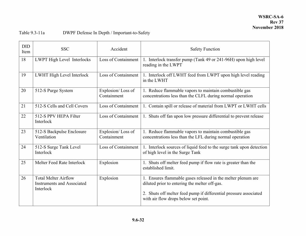
WSRC-SA-6 Rev 37
November 2018
9.6-32
Table 9.3-11a DWPF Defense In Depth / Important-to-Safety
DID Item
SSC Accident Safety Function
18 LWPT High Level Interlocks Loss of Containment 1. Interlock transfer pump (Tank 49 or 241-96H) upon high level reading in the LWPT
19 LWHT High Level Interlock Loss of Containment 1. Interlock off LWHT feed from LWPT upon high level reading in the LWHT
20 512-S Purge System Explosion/ Loss of Containment
1. Reduce flammable vapors to maintain combustible gas concentrations less than the CLFL during normal operation
21 512-S Cells and Cell Covers Loss of Containment 1. Contain spill or release of material from LWPT or LWHT cells
22 512-S PPV HEPA Filter Interlock
Loss of Containment 1. Shuts off fan upon low pressure differential to prevent release
23 512-S Backpulse Enclosure Ventilation
Explosion/ Loss of Containment
1. Reduce flammable vapors to maintain combustible gas concentrations less than the LFL during normal operation
24 512-S Surge Tank Level Interlock
Loss of Containment 1. Interlock sources of liquid feed to the surge tank upon detection of high level in the Surge Tank
25 Melter Feed Rate Interlock Explosion 1. Shuts off melter feed pump if flow rate is greater than the established limit.
26 Total Melter Airflow Instruments and Associated Interlock
Explosion 1. Ensures flammable gases released in the melter plenum are diluted prior to entering the melter off-gas.
2. Shuts off melter feed pump if differential pressure associated with air flow drops below set point.
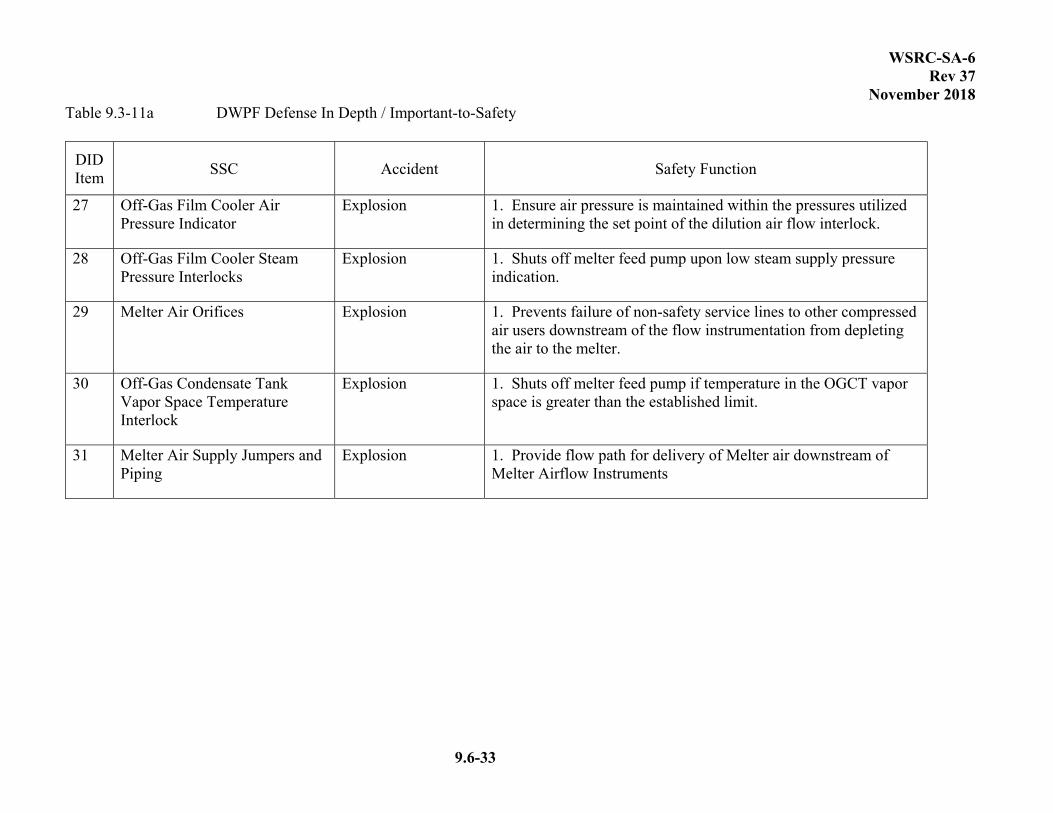
WSRC-SA-6 Rev 37
November 2018
9.6-33
Table 9.3-11a DWPF Defense In Depth / Important-to-Safety
DID Item
SSC Accident Safety Function
27 Off-Gas Film Cooler Air Pressure Indicator
Explosion 1. Ensure air pressure is maintained within the pressures utilized in determining the set point of the dilution air flow interlock.
28 Off-Gas Film Cooler Steam Pressure Interlocks
Explosion 1. Shuts off melter feed pump upon low steam supply pressure indication.
29 Melter Air Orifices Explosion 1. Prevents failure of non-safety service lines to other compressed air users downstream of the flow instrumentation from depleting the air to the melter.
30 Off-Gas Condensate Tank Vapor Space Temperature Interlock
Explosion 1. Shuts off melter feed pump if temperature in the OGCT vapor space is greater than the established limit.
31 Melter Air Supply Jumpers and Piping
Explosion 1. Provide flow path for delivery of Melter air downstream of Melter Airflow Instruments

WSRC-SA-6 Rev 37
November 2018
9.6-34
Table 9.3-12 Consequence Evaluation Levels for Hazard Receptors
Consequence Level (Abbreviation)
Offsite Public Facility Worker Collocated Worker
**High (H)
Non-rad/ Non-chemical
Injury*
Prompt worker fatality; serious injury that is
immediately life threatening or permanently disabling;
Prompt worker fatality, serious injury that is
immediately life threatening or permanently
disabling
Radiological C > 25 rem
C> 100 rem; or radiological material
quantity exceeds Hazard Category 3 threshold (per DOE-STD-1027); or high consequence injury due to
radiological release or exposure
C > 100 rem; or high consequence injury due to
radiological release or exposure
Chemical C > PAC-2
Uniform distribution of total releaseC > PAC-3, or high consequence injury due to
chemical release or exposure
C > PAC-3; or
29 CFR 1910.119 TQ released;or high
consequence injury due to chemical release or
exposure
**Moderate (M)
Non-rad/ Non-chemical
Injury
Serious injury, no immediate loss of life, no permanent
disabilities, hospitalization required
Serious injury, no immediate loss of life, no
permanent disabilities, hospitalization required
Radiological 5.0 C < 25 rem 25 C < 100 rem; or
moderate consequence radiological related injury
25 C < 100 rem; or moderate consequence
radiological related injury
Chemical PAC-1 C < PAC-2
Uniform distribution of total release PAC-2 C < PAC-3; or moderate consequence
chemical related injury
PAC-2 C < PAC-3; or moderate consequence chemical related injury
**Low (L)
Non-rad./ Non-chemical
injury
Minor injuries, no hospitalization
Minor injuries, no hospitalization
Radiological 0.5 C < 5.0 rem 5.0 C < 25 rem or low consequence radiological
related injuries
5.0 C < 25 rem or low consequence radiological
related injuries
Chemical PEL-TWA C < PAC-1
Uniform distribution of total release PAC-1 C < PAC-2
or low consequence chemical related injuries
PAC-1 C < PAC-2 or low consequence chemical
related injuries
Negligible (N)
All < Low < Low < Low
* *SS required in nuclear facilities for prompt fatality, life threatening, or permanently disabling injuries for non-rad/non-chemical events that are not covered by national codes and standards.
*** DID/ITS controls are identified as part of the control selection typically after SC or SS controls (if required) have been selected. DID/ITS control selection is only required in the final HA. See Appendix L [of SCD-11] for additional information on DID/ITS.

WSRC-SA-6 Rev 37
November 2018
9.6-36
Table 9.3-14 – Deleted

WSRC-SA-6 Rev 37
November 2018
9.6-37
Table 9.3-15 – CHA HAZOP Nodes
NODE NO. Node
1 LWPT 2 LWPT/LWHT/Overflow Lines to Sump 3 Steam Jet TL from LWPT to LWHT 4 LWPT/LWHT/Dip Tubes 5 Nitrogen Purge to LWPT/LWHT 6 LWPT/LWHT/Cell Sump Steam Jet 7 Wash Water to LWPT 8 Flush Water to LWPT/LWHT 9 MST Addition Line to LWPT Line 10 Agitator Lube Line to LWPT/LWHT 11 LWPT/ LWHT Vent to 512-S Process Vessel Ventilation System (PPV) 12 LWHT 13 Steam Jet TL from LWHT to LWPT (steam is not available) 14 Drain System to LWHT 15 Nitrogen Sparge to LWHT (Sparger is Now Filtrate Secondary Filter) 16 Lab Sampler System 17 512-S PPV Drain Line to LWHT 18 Crossflow Filter – Filtrate Line 19 Crossflow Filter – MST/Sludge Solids Line 20 512-S Facility
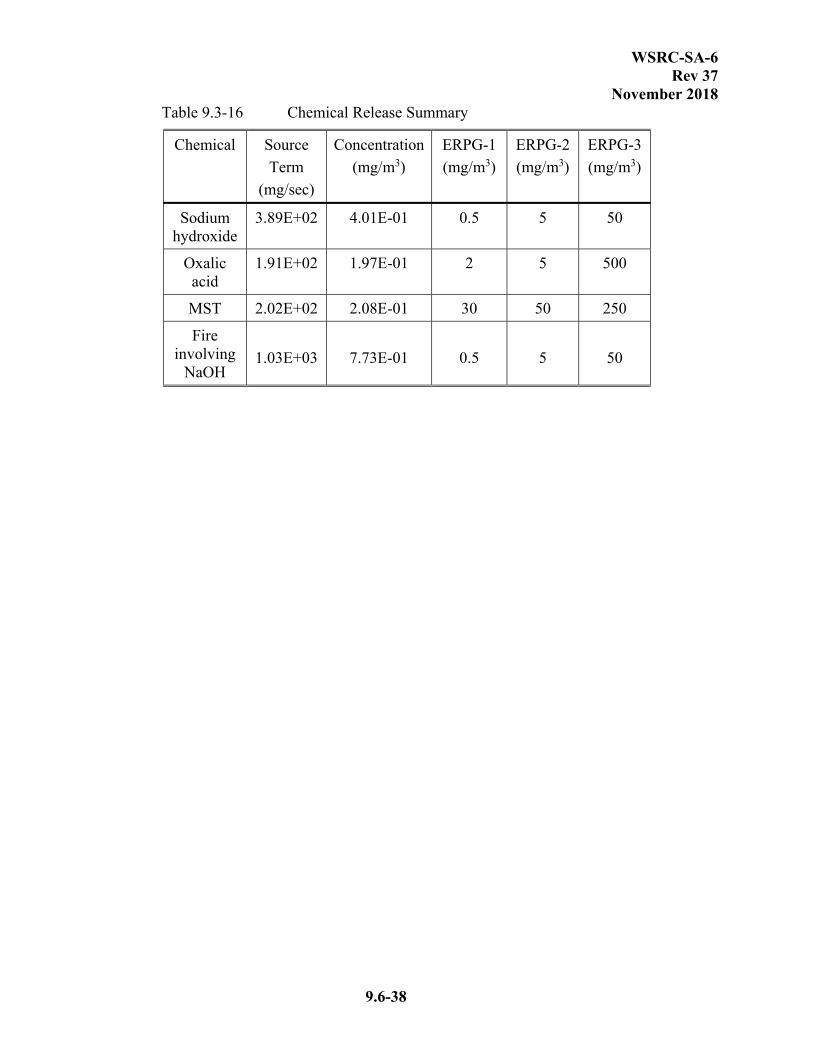
WSRC-SA-6 Rev 37
November 2018
9.6-38
Table 9.3-16 Chemical Release Summary
Chemical Source
Term
(mg/sec)
Concentration
(mg/m3)
ERPG-1
(mg/m3)
ERPG-2
(mg/m3)
ERPG-3
(mg/m3)
Sodium hydroxide
3.89E+02 4.01E-01 0.5 5 50
Oxalic acid
1.91E+02 1.97E-01 2 5 500
MST 2.02E+02 2.08E-01 30 50 250
Fire involving
NaOH
1.03E+03
7.73E-01
0.5
5
50

WSRC-SA-6 Rev 37
November 2018
9.6-39
Table 9.4-1a DWPF Curie Balance with MCU Strip Effluent ****
Isotope
Strip Effluent Stream
(Ci/gal)
Sludge Stream
(Ci/gal)
SRAT Stream
(Ci/gal)
Condensate Stream***
(Ci/gal)
Melter Stream
(Ci/lb)
Melter Off-gas Stream
(Ci/ft3)
Recycle Stream**
*
(Ci/gal)
DWTT Stream***
(Ci/gal)
Off-Gas Condensate
Stream
(Ci/gal)
Co-60 1.50E-01 2.73E-01 6.20E-04 9.62E-02 5.04E-06 9.16E-02 5.45E-02 1.42E-03
Sr-90* 4.05E+01 7.38E+01 1.68E-01 2.63E+01 1.36E-03 2.48E+01 1.47E+01 3.85E-01
Y-90 4.16E+01 7.58E+01 1.72E-01 2.70E+01 1.40E-03 2.54E+01 1.51E+01 3.95E-01
Ru-106* 2.00E+00 3.64E+00 1.61E-02 1.28E+00 1.34E-04 1.23E+00 7.27E-01 3.71E-02
Rh-106 2.01E+00 3.66E+00 1.62E-02 1.28E+00 1.35E-04 1.23E+00 7.31E-01 3.73E-02
Cs-134 1.41E-01 2.57E-01 6.37E-03 8.22E-02 5.18E-05 9.00E-02 5.13E-02 1.46E-02
Cs-137* 1.65E+01 1.34E+00 3.41E+01 8.46E-01 1.10E+01 6.86E-03 1.21E+01 6.84E+00 1.45E+00
Ba-137m 1.56E+01 1.28E+00 3.22E+01 7.99E-01 1.03E+01 6.48E-03 1.14E+01 6.46E+00 1.38E+00
Ce-144* 8.74E+00 1.59E+01 3.61E-02 5.62E+00 2.94E-04 5.33E+00 3.17E+00 8.29E-02
Pr-144 8.74E+00 1.59E+01 3.61E-02 5.62E+00 2.94E-04 5.33E+00 3.17E+00 8.31E-02
Pm-147* 2.14E+01 3.90E+01 8.85E-02 1.37E+01 7.18E-04 1.31E+01 7.78E+00 2.04E-01
Eu-154 5.48E-01 9.98E-01 2.27E-03 3.52E-01 1.84E-05 3.35E-01 1.99E-01 5.23E-03
Pu-238* 1.30E+00 2.37E+00 5.39E-03 8.38E-01 4.38E-05 7.95E-01 4.73E-01 1.24E-02
Pu-239* 1.13E-02 2.06E-02 4.69E-05 7.28E-03 3.81E-07 6.91E-03 4.11E-03 1.07E-04
Pu-240* 7.59E-03 1.38E-02 3.14E-05 4.87E-03 2.56E-07 4.63E-03 2.75E-03 7.22E-05
Pu-241* 1.46E+00 2.66E+00 6.05E-03 9.42E-01 4.92E-05 8.92E-01 5.31E-01 1.39E-02
Am-241* 9.47E-03 1.72E-02 3.92E-05 6.10E-03 3.18E-07 5.77E-03 3.43E-03 9.00E-05
Cm-244* 9.40E-02 1.71E-01 3.89E-04 6.04E-02 3.17E-06 5.74E-02 3.41E-02 8.92E-04
Sb-125** 7.34E-01 1.34E+00 3.03E-03 4.72E-01 2.47E-05 4.50E-01 2.67E-01 6.98E-03
Te-125m** 2.56E-01 4.66E-01 6.22E-03 1.57E-01 5.15E-05 1.60E-01 9.30E-02 6.98E-03
* Isotopes identified as major contributors to Inhalation Dose Potential (Ref. 170). ** Sb-125 and Te-125m were used in melter events
*** Condensate Stream is process condensate. The Recycle stream, which is present in the RCT and RPT, is a mixture of SRAT Stream, Strip Effluent, and Condensate Stream, as discussed in Section 9.4.1.2. The DWTT stream is a mixture of SRAT Stream, Strip Effluent, and non radiolytic liquid as discussed in Section 9.1.4.2.
**** The WAC IDP Limit for the Sludge Stream restricts the radionuclide inventory to less than what is listed for the Sludge, SRAT, and downstream streams.

WSRC-SA-6 Rev 37
November 2018
9.6-40
Table 9.4-1b 512-S Inventory
Stream
512-S Feed Stream MST/Sludge Solids (at LWPT vessel heel)
***
Filtrate
Isotope (Ci/gal) (Ci/gal) (Ci/gal)
Am-241* 7.08E-03 1.17E-02 7.11E-03
Ba-137m** 1.05E+00 1.68E+00 1.05E+00
Ce-144* 6.56E-02 4.36E+00 9.18E-02
Cm-244* 7.06E-04 4.69E-02 9.88E-04
Co-60 1.13E-03 7.49E-02 1.58E-03
Cs-134 1.06E-03 7.04E-02 1.48E-03
Cs-137* 1.11E+00 1.77E+00 1.11E+00
Eu-154 4.11E-03 2.74E-01 5.76E-03
Pm-147* 1.61E-01 1.07E+01 2.25E-01
Pr-144 6.56E-02 4.36E+00 9.18E-02
Pu-238* 9.76E-03 6.49E-01 1.37E-02
Pu-239* 1.46E-04 5.70E-03 1.80E-04
Pu-240* 7.06E-05 3.80E-03 9.34E-05
Pu-241* 1.12E-02 7.29E-01 1.56E-02
Rh-106 1.51E-02 1.00E+00 2.11E-02
Ru-106* 1.50E-02 9.98E-01 2.10E-02
Sb-125 5.51E-03 3.66E-01 7.71E-03
Sr-90* 3.05E-01 2.02E+01 4.27E-01
Y-90 3.14E-01 2.08E+01 4.38E-01
* Isotopes identified as major contributors to Inhalation Dose Potential (Ref. 170).
** This isotope has a very short half-life and it is not explicitly input into MACCS2 since its dose contribution is accounted for by its parent (Cs-137 is the parent of Ba-137m).
*** The WAC IDP Limit for the MST/Sludge Solids Stream restricts the radionuclide inventory to less than what is listed.

WSRC-SA-6 Rev 37
November 2018
9.6-41
Table 9.4-2 Vessels and Characteristic Streams
Vessel Stream Maximum Inventory (gallons)
Overflow Volume (gallons)
Minimum Volume (gallons)
SPT Sludge Stream 7050 6217 650
PPT MST/Sludge Solids 7050 6466 700
RPT Recycle Stream 7050 6179 650
LWPT MST/Sludge Solids 7000 6204 191
LWHT Filtrate 7000 6204 191
SEFT Strip Effluent Stream** 12,000 10,657 1400
PRFT MST/Sludge Solids 9,000 8,310* 750
SME SRAT Stream 12,000 11,298 1400
SRAT SRAT Stream 12,000 10,928 1400
SMECT SRAT Stream 12,000 11,263 1200
MFT SRAT Stream 12,000 11,089 1800
RCT Recycle Stream 12,000 10,479 1400
DWTT DWTT Stream 12,000 11,298 1400
Melter Melter Stream 1,414 888 476
OGCT Off-Gas Condensate 12,000 N/A N/A
BUOGCT Off-Gas Condensate 12,000 N/A N/A
Melter Off-gas
Melter Off-Gas Stream Modeled as continuous discharge
N/A N/A
Canister Melter Stream 4,463 lbs N/A N/A
* The overflow of the PRFT has a pressure relief valve installed on it (Ref. 177)
** Consequence analysis may assume some percentage of MST/Sludge Solids in the SEFT.
WSRC-SA-6 Rev 37
November 2018
9.6-42
Table 9.4-3 through 9.4-5 Deleted
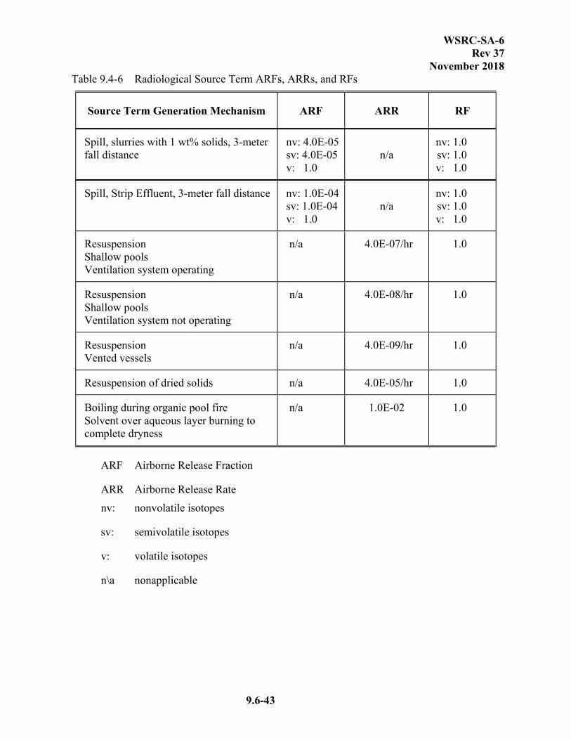
WSRC-SA-6 Rev 37
November 2018
9.6-43
Table 9.4-6 Radiological Source Term ARFs, ARRs, and RFs
Source Term Generation Mechanism ARF ARR RF
Spill, slurries with 1 wt% solids, 3-meter fall distance
nv: 4.0E-05 sv: 4.0E-05 v: 1.0
n/a
nv: 1.0 sv: 1.0 v: 1.0
Spill, Strip Effluent, 3-meter fall distance nv: 1.0E-04 sv: 1.0E-04 v: 1.0
n/a
nv: 1.0 sv: 1.0 v: 1.0
Resuspension Shallow pools Ventilation system operating
n/a 4.0E-07/hr 1.0
Resuspension Shallow pools Ventilation system not operating
n/a 4.0E-08/hr 1.0
Resuspension Vented vessels
n/a 4.0E-09/hr 1.0
Resuspension of dried solids n/a 4.0E-05/hr 1.0
Boiling during organic pool fire Solvent over aqueous layer burning to complete dryness
n/a 1.0E-02 1.0
ARF Airborne Release Fraction
ARR Airborne Release Rate
nv: nonvolatile isotopes
sv: semivolatile isotopes
v: volatile isotopes
n\a nonapplicable

WSRC-SA-6 Rev 37
November 2018
9.6-44
Table 9.4-7 Decontamination Factors (DFs) for Vitrification Building Radiological Releases
Building/Ventilation Status
Vitrification Building Deposition
DF
Sand Filter Filtration DF
Total DF
Building Collapse 1.0 1.0 1.0
Building Breach w/o Ventilation
1.3 1.0 1.3
Building Breach w/Ventilation
1.0 200 200
Ventilation Failure 1.4 1.0 1.4
Normal Operation 1.0 200 200

WSRC-SA-6 Rev 37
November 2018
9.6-45
Table 9.4-8 Through 9.4-10 Deleted
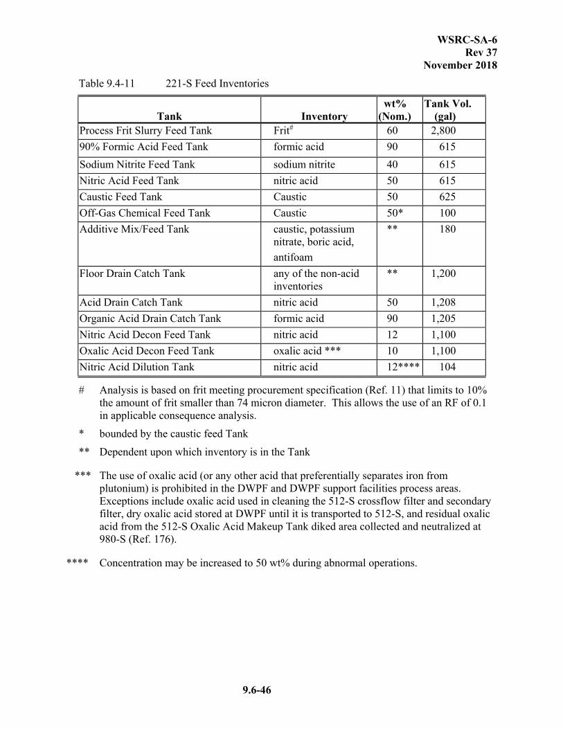
WSRC-SA-6 Rev 37
November 2018
9.6-46
Table 9.4-11 221-S Feed Inventories
Tank
Inventory
wt% (Nom.)
Tank Vol. (gal)
Process Frit Slurry Feed Tank Frit# 60 2,800
90% Formic Acid Feed Tank formic acid 90 615
Sodium Nitrite Feed Tank sodium nitrite 40 615
Nitric Acid Feed Tank nitric acid 50 615
Caustic Feed Tank Caustic 50 625
Off-Gas Chemical Feed Tank Caustic 50* 100
Additive Mix/Feed Tank caustic, potassium nitrate, boric acid,
antifoam
** 180
Floor Drain Catch Tank any of the non-acid inventories
** 1,200
Acid Drain Catch Tank nitric acid 50 1,208
Organic Acid Drain Catch Tank formic acid 90 1,205
Nitric Acid Decon Feed Tank nitric acid 12 1,100
Oxalic Acid Decon Feed Tank oxalic acid *** 10 1,100
Nitric Acid Dilution Tank nitric acid 12**** 104
# Analysis is based on frit meeting procurement specification (Ref. 11) that limits to 10% the amount of frit smaller than 74 micron diameter. This allows the use of an RF of 0.1 in applicable consequence analysis.
* bounded by the caustic feed Tank
** Dependent upon which inventory is in the Tank
*** The use of oxalic acid (or any other acid that preferentially separates iron from plutonium) is prohibited in the DWPF and DWPF support facilities process areas. Exceptions include oxalic acid used in cleaning the 512-S crossflow filter and secondary filter, dry oxalic acid stored at DWPF until it is transported to 512-S, and residual oxalic acid from the 512-S Oxalic Acid Makeup Tank diked area collected and neutralized at 980-S (Ref. 176).
**** Concentration may be increased to 50 wt% during abnormal operations.

WSRC-SA-6 Rev 37
November 2018
9.6-47
Table 9.4-12 Deleted
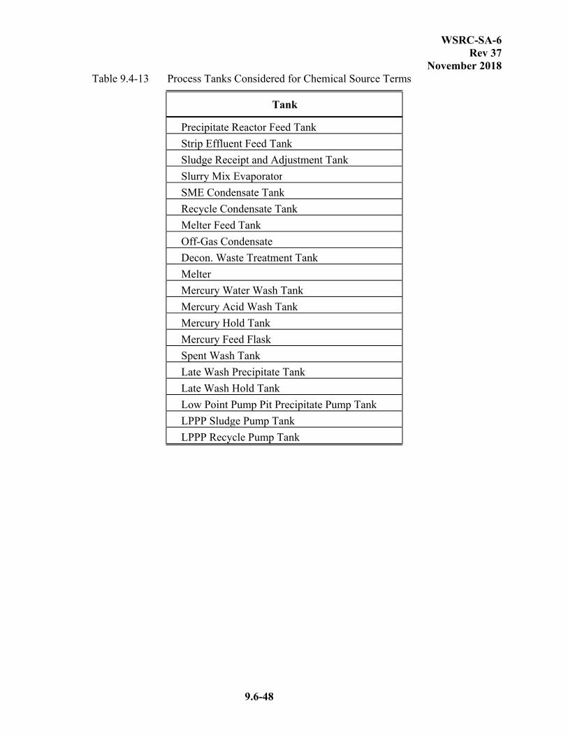
WSRC-SA-6 Rev 37
November 2018
9.6-48
Table 9.4-13 Process Tanks Considered for Chemical Source Terms
Tank
Precipitate Reactor Feed Tank
Strip Effluent Feed Tank
Sludge Receipt and Adjustment Tank
Slurry Mix Evaporator
SME Condensate Tank
Recycle Condensate Tank
Melter Feed Tank
Off-Gas Condensate
Decon. Waste Treatment Tank
Melter
Mercury Water Wash Tank
Mercury Acid Wash Tank
Mercury Hold Tank
Mercury Feed Flask
Spent Wash Tank
Late Wash Precipitate Tank
Late Wash Hold Tank
Low Point Pump Pit Precipitate Pump Tank
LPPP Sludge Pump Tank
LPPP Recycle Pump Tank
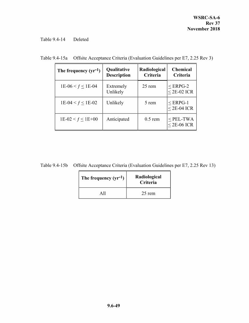
WSRC-SA-6 Rev 37
November 2018
9.6-49
Table 9.4-14 Deleted
Table 9.4-15a Offsite Acceptance Criteria (Evaluation Guidelines per E7, 2.25 Rev 3)
The frequency (yr-1) Qualitative Description
Radiological Criteria
Chemical Criteria
1E-06 < ƒ < 1E-04 Extremely Unlikely
25 rem < ERPG-2 < 2E-02 ICR
1E-04 < ƒ < 1E-02 Unlikely 5 rem < ERPG-1 < 2E-04 ICR
1E-02 < ƒ < 1E+00 Anticipated 0.5 rem < PEL-TWA < 2E-06 ICR
Table 9.4-15b Offsite Acceptance Criteria (Evaluation Guidelines per E7, 2.25 Rev 13)
The frequency (yr-1) Radiological Criteria
All 25 rem

WSRC-SA-6 Rev 37
November 2018
9.6-50
Table 9.4-16 Hierarchy of Alternative Concentration Limits
Primary Concentration Limit**
Hierarchy of Alternative Limits
ERPG-2 EEGL (60 min.) LOC PEL-C TLV-C TLV-TWA*
ERPG-1 PEL-STEL TLV-STEL TLV-TWA*
PEL-TWA TLV-TWA SPEGL (60 min.) CEGL
*Applicable only to chemicals whose effects are dose-dependent
** For 512-S and DWPF CHA, chemical analyses, values for concentration limit could have been based on either AEGLs, ERPGs, or TEELs.
WSRC-SA-6 Rev 37
November 2018
9.6-51
Tables 9.4-17 through 9.4-27 Deleted

WSRC-SA-6 Rev 37
November 2018
9.6-52
Table 9.4-28 DWPF Vitrification Building Vessel Explosion Combined Consequences
Event
Unmitigated Offsite
Consequences (rem)
Unmitigated Onsite
Consequences1
(rem)
Reference
Explosion in the SEFT and pool fire 0.20 > 100
S-CLC-S-00153, Table 14
Explosion in SRAT and pool fire 0.49 > 100
S-CLC-S-00153, Table 14
Explosion in SMECT and pool fire 0.49 > 100
S-CLC-S-00153, Table 14
Explosion in SME 0.49 > 100
S-CLC-S-00153, Table 14
Explosion in MFT 0.49 > 100
S-CLC-S-00153, Table 14
Explosion in PRFT and pool fire 0.15 > 100
S-CLC-S-00153, Table 14
Melter heated volatile release 0.8 > 100
S-CLC-S-00153, Table 14
Explosion in RCT 0.17 > 100
S-CLC-S-00153, Table 14
Explosion in DWTT 0.045 >100
S-CLC-S-00153, Table 14
Vitrification bldg canisters crush 0.0115 39.5
S-CLC-S-00153, Table 14
Total <3.4 > 100
1Onsite consequences include an increase by a factor of 10 to incorporate DOE Interim Guidance (Ref. 186).
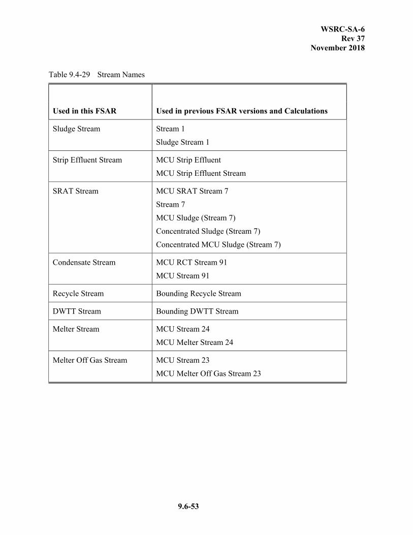
WSRC-SA-6 Rev 37
November 2018
9.6-53
Table 9.4-29 Stream Names
Used in this FSAR Used in previous FSAR versions and Calculations
Sludge Stream Stream 1
Sludge Stream 1
Strip Effluent Stream MCU Strip Effluent
MCU Strip Effluent Stream
SRAT Stream MCU SRAT Stream 7
Stream 7
MCU Sludge (Stream 7)
Concentrated Sludge (Stream 7)
Concentrated MCU Sludge (Stream 7)
Condensate Stream MCU RCT Stream 91
MCU Stream 91
Recycle Stream Bounding Recycle Stream
DWTT Stream Bounding DWTT Stream
Melter Stream MCU Stream 24
MCU Melter Stream 24
Melter Off Gas Stream MCU Stream 23
MCU Melter Off Gas Stream 23


WSRC-SA-6 Rev 37
November 2018
9.7-3
Figure 9.4-1 Process Chemical Screening Methodology
Process Inventories
Apply: ARF=1; RF=1source
term Onsite X/Qconc
Do onsite concentrations
exceed bounding acceptance criteria?
source term screened out (all process inventory
source terms are in this category)
Apply: ARFs and RFs
corresponding to source term generation
mechanisms
Apply: Offsite dispersion factors to gas-phase source terms
Do offsite concentrations exceed bounding acceptance
criteria?
no
no
no
yes
yes
yes
source term not screened out (no source terms in this category)
Do onsite concentrations
exceed bounding acceptance criteria?